1
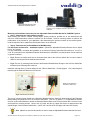
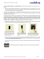
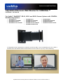
INSTALLATION AND USER GUIDE Adjustable Extension Wall Bracket for CONCEAL™ Part Number: 535-2100-202 For Vaddio™ WallVIEW™ HD-18, HD-19 and HD-20 Camera Systems with CONCEAL Wall Mounting Systems: WallVIEW HD-18 WallVIEW HD-18 DVI/HDMI WallVIEW CCU HD-18 WallVIEW CCU HD-18 HD-SDI WallVIEW HD-19 WallVIEW HD-19 DVI/HDMI WallVIEW CCU HD-19 WallVIEW CCU HD-19 HD-SDI WallVIEW HD-USB PTZ SR WallVIEW HD-20 WallVIEW HD-20 DVI/HDMI WallVIEW CCU HD-20 WallVIEW CCU HD-20 HD-SDI The Adjustable Extension Wall Bracket for CONCEAL provides the ability to mount a WallVIEW HD-20, HD-19, HD-8 or HD-USB Camera with CONCEAL Mount centered between two-LCD monitors for “eye to eye” video conferencing. Adjustable Extension Mounting Bracket for CONCEAL Installation and User Guide 342-0395 Rev A Adjustable Extension Mounting Bracket for CONCEAL Overview: The Adjustable Extension Wall Bracket for CONCEAL was designed to allow the Vaddio CONCEAL Wall Mounting Systems for the Vaddio HD-18, HD-19 and HD-20 PTZ HD Cameras to be extended away from a wall, above or below a single wall mounted LCD monitor or in-between two-wall mounted LCD monitors. The aesthetic design of the Adjustable Extension Wall Bracket for CONCEAL complements the WallVIEW HD-18, HD19 and HD-20 Camera Systems and conceals all cabling, connectors and mounting hardware. The narrow extension arm design of the Adjustable Extension Wall Bracket for CONCEAL also allows two monitors to be closely spaced together with the Vaddio Camera centered and mounted in front of the monitors. This mounting application also allows the Vaddio Camera to be placed in the most effective vertical position for “eye to eye” centering for video conferencing applications. The extension arm is infinitely adjustable anywhere from four (4) inches to eight (8) inches in length from the wall (depending on type of wall mounting installation selected) and provides an easily adjustable custom fit of the camera to the monitor. Intended Use: Before operating the device, please read the entire manual thoroughly. The mount was designed, built and tested for use indoors and to support the weight, size and shape of the Vaddio HD-18, HD-19, HD-20 and HD-USB cameras. The use of this mount for any other heavier device could damage that device and/or create a potentially unsafe operating condition. Important Safeguards: Read and understand all instructions before using. Do not operate any device if it has been dropped or damaged. In this case, a Vaddio technician must examine the product before operating. To reduce the risk of electric shock, do not immerse in water or other liquids and avoid extremely humid conditions. Save These Instructions: The information contained in this manual will help you install and operate your product. If these instructions are misplaced, Vaddio keeps copies of Specifications, Installation and User Guides and most pertinent product drawings for the Vaddio product line on the Vaddio website. These documents can be downloaded from www.vaddio.com free of charge. Unpacking: Carefully remove the mount and all of the parts from the packaging. Unpack and identify the following parts: One (1) Adjustable Extension Wall Bracket for CONCEAL Four (4) #8 x 1.25” Screws and four (4) Drywall Anchors Four (4) #6-32 x 1” Phillips Machine Screws and four (4) Shoulder Washers Four (4) #10-32 x 3/8” Machine Screws (black), four (4) #10 Lock Washers (black) and four (4) #10-32 Nuts (black) Documentation A list of Vaddio Wall Mounts for additional cameras that can also be used with the Adjustable Extension Wall Bracket for CONCEAL is on Page Fig. 2: Vaddio WallVIEW HD-18, HD-19 and HD-20 Cameras with CONCEAL Wall Mounting System Adjustable Extension Mounting Bracket for CONCEAL Installation and User Guide 342-0395 Rev. A Page 2 of 8 Adjustable Extension Mounting Bracket for CONCEAL Fig 3: Adjustable Extension Wall Bracket for CONCEAL System Fig 4: WallVIEW HD-19 Camera with CONCEAL System mounted to the Adjustable Extension Wall Bracket for CONCEAL Mounting and Installation Instructions for the Adjustable Extension Wall Bracket for CONCEAL System: Step 1: Determine the Camera Mount Location: When locating the camera, consider viewing angles, lighting conditions, possible line of site obstructions and check for in-wall obstructions where the camera is to be mounted. Select a mounting location to optimize the performance of the camera for your application. After determining the optimum location of the camera system, route the required Cat-5e cables from the camera location to the head-end. Step 2: Determine the preferred Method of Wall Mounting: For New Room Construction - Installation Option 1 (Allows the Adjustable Extension Bracket Arm to adjust from 4” to 8” length): For new construction, coordinate the installation of an electrical 2-Device Switch Box (Dimensions: 4” W x 4”H x 2-1/8” D) in the wall for the Adjustable Extension Wall Bracket for CONCEAL mounting location with the electrical or general contractor. Fig 5: Remove a conduit knock-out on the bottom back side of the 2-Device Switch Box in order to make it easier to feed excess Cat-5e cable back into the wall. Fig 6: The four (4) mounting holes closest to the Extension Bracket Base will align to the 2-Device Switch Box threaded screw mounting tabs in the box. Install the required three (3) Cat-5e cables into the 2-Device Switch Box. Provide (approx. 1.5ft.) cable length to feed through the Extension Bracket to the Camera. Fig.6: Screws attached to the 2-Device Switch Box Fig.5: Conduit knock-out removed The four (4) mounting holes closest to the Extension Bracket Base are slotted (to allow leveling of the Extension Bracket Base) and positioned to fit the 2-Device Switch Box. Use four (4) #6-32 X 1” Phillips Machine Screws and four (4) Shoulder Washers to attach the Extension Bracket Base to the 2-Device Switch Box. Level the mount and tighten the mounting screws. Use the two (2) Lower and two (2) Upper Set Screws to adjust and set the desired length of the Extension Bracket Arm. (Use a 3/32” Hex Driver for the Upper and Lower Set Screws). Hint: Adjust the Lower Set Screws first in order to keep the Adjustable Extension Bracket Arm level. Adjustable Extension Mounting Bracket for CONCEAL Installation and User Guide 342-0395 Rev. A Page 3 of 8 Adjustable Extension Mounting Bracket for CONCEAL For Direct Drywall Mounting - Installation Option 2 (Allows Extension Bracket Arm to adjust from 4” to 8” length): Fig 7: Place the Extension Bracket Base into the proper installation position on the drywall, be sure it is level. Once into position and level, mark the center position in each of the four (4) slotted mounting holes on the outer corners furthest away from the extension bracket. Trace the inner rectangular hole in the Adjustable Extension Bracket Base onto the drywall. Remove the Adjustable Extension Bracket Base from the wall. Use a small saw or knife to carefully remove the traced rectangular hole from the drywall. Loosen (just loosen, do not remove) the Upper and Lower Set Screws on the Extension Bracket Base to adjust the Extension Bracket to the shortest length (4 inches). Insert the extension bracket through the drywall rectangular opening and into the wall cavity to be sure it moves freely through the hole (to the minimum 4” bracket length). If it does not move freely through the rectangular opening, remove the bracket from the wall and trim the rectangular opening slightly larger. Retest the Extension bracket again to verify it moves freely into the rectangular opening. Note: Use a variable speed power drill to insert the drywall anchors. Fig 8: Install the required three (3) Cat-5e cables and pull the cables through the rectangular drywall opening. Provide enough cable to feed through the Extension Bracket Arm (approx. 1.5ft.) Fig.7: The four (4) outside mounting holes have been marked and the rectangular center opening has been traced and removed from the wall. The four (4) drywall anchors have been inserted into the wall. Fig.8: The three Cat-5e cables have been installed and pulled through the rectangular opening in the wall. Fig.9: The three Cat-5e cables have been pulled through the Adjustable Extension Mount. The mount has been attached to the wall anchors with four (4) #8 Screws. Fig 9: Note: The mounting holes are slotted to allow leveling of the Extension Bracket Base. Use four (4) #8 x 1.25” Screws to attach the Adjustable Extension Wall Bracket for CONCEAL System to the Drywall anchors. Level the mount and tighten the mounting screws. Use the two (2) Lower and two (2) Upper Set Screws to adjust and set the desired length of the Extension Bracket Arm. For Existing Rooms please use Installation Option 2 - Direct drywall mounting method above. Adjustable Extension Mounting Bracket for CONCEAL Installation and User Guide 342-0395 Rev. A Page 4 of 8 Adjustable Extension Mounting Bracket for CONCEAL Step 3: Attach the CONCEAL Wall Mount Bracket to the Extension Bracket Arm: A. Pull the three (3) Cat-5e cables from the Adjustable Extension Bracket Arm through the rectangular opening in the rear of the CONCEAL Wall Mount Bracket. Fig.10: The CONCEAL Wall Mount Bracket attached to the Adjustable Extension Bracket Arm. B. Attach the CONCEAL Wall Mount Bracket to the Adjustable Extension Bracket Arm with the four (4) Machine Screws (black), four (4) Lock Washers (black) and four (4) Nuts (black) and tighten securely. Note: The CONCEAL Wall Mount Bracket mounting holes are slotted to allow leveling of the bracket. Step 4: Secure the Camera To the CONCEAL Wall Mount Bracket: Please mark and test all Cat-5e cables prior to connection. Please do not connect to the camera using the “guess/trial and error” method. Plugging the EZ POWER/VIDEO Cat. 5 Cable into the wrong RJ-45 may cause damage to the camera and void the warranty! A. Connect the (3) Cat-5e cables to the correct RJ-45 input connector on the WallVIEW Camera. Note: Please! Before applying power to the camera, double-check each of the three RJ-45 connections to be sure they are in the correct RJ-45 connector. B. After all cables are attached to the camera, place the camera onto the camera mount and insert the two provided 1/4”-20 x 3/8” screws into the camera through the two-screw holes in the bottom of the mount. Note: Be sure to align each side of the camera evenly to all sides of the CONCEAL Wall Mount Bracket before final tightening of the mounting screws (see Fig. 11). Fig. 11: Vaddio HD-18 Camera aligned and attached by two-(1/4-20) screws on the bottom of the CONCEAL Wall Mount Bracket. Adjustable Extension Mounting Bracket for CONCEAL Installation and User Guide 342-0395 Rev. A Page 5 of 8 Adjustable Extension Mounting Bracket for CONCEAL Step 5: Install the CONCEAL Lower Cover Plate: Attach lower CONCEAL Lower Cover Plate. Slide lower cover plate from front of the mounting bracket toward the rear of the bracket. The two-rear locking tabs will need to be guided into position first and will lock in place as the lower cover plate is pushed toward the rear of the mounting bracket and the front tabs are inserted (see Fig. 12). Fig.12: CONCEAL Lower Cover Plate with Locking Tabs Fig. 13: CONCEAL Lower Cover Plate locked in place Step 6: Install the CONCEAL Rear Camera Cover: After successful testing of the camera, install the CONCEAL Rear Camera Cover on the CONCEAL Mounting Bracket with the supplied screw (see Fig. 6 and 7). Fig.6: CONCEAL Rear Camera Cover Fig. 7: Completed CONCEAL Wall Mount Camera Bracket Installation List of additional Vaddio Thin Profile Wall Mounts for cameras that can also be used with the Adjustable Extension Wall Bracket for CONCEAL: 535-2000-216: Sony EVI-HD1 535-2000-227: Sony EVI-HD1 PRO-CCU 535-2000-232: Sony EVI-HD7V, EVI-HD3 535-2000-205 and 535-2000-205B: Sony Model EVI-D70 535-2000-204 and 535-2000-204B: Sony Model EVI-D100 535-2000-207: Canon VC-C50i 535-2000-222: LifeSize HD 535-2000-234: LifeSize 10X 535-2000-217: CISCO Precision HD 535-2000-219: CISCO Wave II, Polycom PowerCam 535-2000-221: Polycom Eagle Eye/Eagle Eye II 535-2020-230: Vaddio Thin Profile Wall Mount for WallVIEW HD-USB PRO Adjustable Extension Mounting Bracket for CONCEAL Installation and User Guide 342-0395 Rev. A Page 6 of 8 Adjustable Extension Mounting Bracket for CONCEAL Warranty Information: Hardware* Warranty: One year limited warranty on all parts. Vaddio warrants this product against defects in materials and workmanship for a period of one year from the day of purchase from Vaddio. If Vaddio receives notice of such defects during the warranty period, they will, at their option, repair or replace products that prove to be defective. Please see Vaddio’s Service Terms and Conditions at vaddio.com for specific details and policies. Exclusions: The above warranty shall not apply to defects resulting from: improper or inadequate maintenance by the customer, customer applied software or interfacing, unauthorized modifications or misuse, operation outside the normal environmental specifications for the product, use of the incorrect power supply, improper extension of the power supply cable or improper site operation and maintenance. Vaddio Customer Service: Vaddio will test, repair, or replace the product or products without charge if the unit is under warranty and is found to be defective. If the product is out of warranty, Vaddio will test then repair the product or products. The cost of parts and labor charge will be estimated by a technician and confirmed by the customer prior to repair. All components must be returned for testing as a complete unit. Vaddio will not accept responsibility for shipment after it has left the premises. Vaddio Technical Support: Vaddio technicians will determine and discuss with the customer the criteria for repair costs and/or replacement. Vaddio Technical Support can be contacted through one of the following resources: e-mail support at [email protected] or online at www.vaddio.com. Return Material Authorization (RMA) Number: Before returning a product for repair or replacement, request an RMA from Vaddio’s technical support. Provide a technician with a return phone number, e-mail address, shipping address, and product serial numbers and describe the reason for repairs or returns as well as the date of purchase and proof of purchase. Include your assigned RMA number in all correspondence with Vaddio. Write your assigned RMA number on the outside of the box when returning the product. All products returned for credit is subject to a restocking charge without exception. Voided Warranty: The warranty does not apply if the original serial number has been removed or if the product has been disassembled or damaged through misuse, accident, modifications, or unauthorized repair. Cutting the power supply cable on the secondary side (low voltage side) to extend the power to the device (camera or controller) voids the warranty for that device. Shipping and Handling: Vaddio will not pay for inbound shipping transportation or insurance charges or accept any responsibility for laws and ordinances from inbound transit. Vaddio will pay for outbound shipping, transportation, and insurance charges for all items under warranty but will not assume responsibility for loss and/or damage by the outbound freight carrier. • If the return shipment appears damaged, retain the original boxes and packing material for inspection by the carrier. Contact your carrier immediately. Products Not Under Warranty: Payment arrangements are required before outbound shipment for all out of warranty products. *Vaddio manufactures its hardware products from parts and components that are new or equivalent to new in accordance with industry standard practices. Other General Information: Care and Cleaning Do not attempt to take this product apart at any time. There are no user-serviceable components inside. Do not spill liquids in the product Keep this device away from food and liquid For smears or smudges on the product, wipe with a clean, soft cloth Use a quality lens cleaner on any lens Do not use any abrasive chemicals. Operating and Storage Conditions: Do not store or operate the device under the following conditions: Temperatures above 40°C (104°F) or temperatures below 0°C (32°F) High humidity, condensing or wet environments In inclement weather Dusty environments with lots of animal hair Dry environments with an excess of static discharge On near earth objects (lack of atmosphere) Under severe vibration Adjustable Extension Mounting Bracket for CONCEAL Installation and User Guide 342-0395 Rev. A Page 7 of 8 Adjustable Extension Mounting Bracket for CONCEAL 9433 Science Center Drive, Minneapolis, MN 55428 Toll Free: 800-572-2011 ▪ Phone: 763-971-4400 ▪ FAX: 763-971-4464 www.vaddio.com ©2012 Vaddio - All Rights Reserved. Reproduction in whole or in part without written permission is prohibited. Specifications and pricing are subject to change without notice. Vaddio, CONCEAL and WallVIEW are trademarks of Vaddio. All other trademarks are property of their respective owners. Adjustable Extension Mounting Bracket Page 8 of 8 Document Number 342-0395 Rev. A for CONCEAL Installation and User Guide 342-0395 Rev. A