1
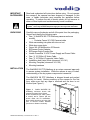
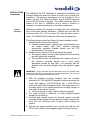
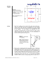
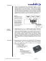
Installation and User Guide
Camera and Electronic Products for Integrators
WallVIEW™ 50i PTZ HideAway
Installed PTZ Wall Camera with Recessed, Motorized In-wall Camera Lift System
INTRODUCTION
The Vaddio WallVIEW 50i PTZ HideAway Camera System is a
mechanically unique and complete product that was designed to
provide system integrators with an easy to install, in-wall, recessed
and motorized camera lift system for use when cameras require
concealment for security or architectural design purposes. The
WallVIEW 50i features the Canon® VC-C50i pan/tilt/zoom camera
which is mounted in a recessed plenum rated enclosure with a
motorized front panel door. When closed, the WallVIEW HideAway
enclosure conceals the camera until the camera is activated, then
the front door drops down and reveals the camera to the meeting
room participants.
The system is equipped with Vaddio’s EZCamera™ Cabling
System. This allows the integrator to use Cat. 5 cabling to run
power and video together on a single Cat.5 and camera control on
a second Cat. 5 run. The VISCA control interface is included to
allow the camera to work with any other VISCA compatible control
device. The PowerRite™ power supply regulates the right amount
of power needed for the camera over the Cat. 5 cabling.
INTENDED USE
Before operating the Vaddio WallVIEW 50i PTZ HideAway, please
read the entire manual thoroughly. The camera system was
designed, built and tested for use indoors and with the provided
power supply. The use of a power supply other than the one
provided or outdoor operation has not been tested and could
damage the camera and/or create a potentially unsafe operating
condition.
SAVE THESE
INSTRUCTIONS
The information contained in this manual will help you install and
operate your Vaddio WallVIEW 50i PTZ HideAway. If these
instructions are misplaced, Vaddio keeps copies of Specifications,
Installation and User Guides and most pertinent product drawings
for the Vaddio product line on the website. These documents can
be downloaded from www.vaddio.com free of charge.
Ⓒ2006 Vaddio - All Rights Reserved. Reproduction in whole or in part without written permission is prohibited. Specifications and
pricing subject to change. CeilingVIEW, WallVIEW ControlVIEW, Quick-Connect, EZCamera and PowerRite are registered
trademarks of Vaddio, Inc. All other trademarks are property of their respective owners. Form Number 341-141 Rev. C.
IMPORTANT
SAFEGAURDS
Read and understand all instructions before using. Do not operate
the camera if the camera has been dropped or damaged. In this
case, a Vaddio technician must examine the appliance before
operating. To reduce the risk of electric shock, do not immerse in
water or other liquids and avoid extremely humid conditions.
Use only the power supply provided with the WallVIEW 50i HideAway camera
system. Use of any unauthorized power supply will void any and all warranties.
UNPACKING
Carefully remove the device and all of the parts from the packaging.
Unpack and identify the following parts:
• One (1) WallVIEW 50i PTZ HideAway camera enclosure
module
o Contains Canon VC-C50i Camera inside
• White surrounding trim plate with door cut out
• White door cover plate
• Canon WL-V5 Multifunction IR Remote
• EZCamera Control Adapter
• EZCamera Quick-Connect Box
• Vaddio PowerRite 15 VDC Power Supply and Power Cable
• One (1) 12’/(3.66m) S-Video Cable
• One (1) 12’/(3.66m) Composite Video Cable
• Installation and Users Guide (document 341-141)
• Mounting Template (document 341-156)
• Mounting hardware
INSTALLATION
The WallVIEW 50i PTZ HideAway is an unique recessed approach
to camera system installation. While the camera is easy to install,
understanding of the key system components is essential.
The WallVIEW 50i PTZ HideAway is shipped closed and packed
securely for transit. Before powering up the camera for the first
time, make sure that any tape is removed and the door is not
blocked (see Figure 1).
Figure 1: Vaddio WallVIEW 50i
HideAway enclosure shown with
camera lift system (door) closed.
RJ-45 connections (for video, power
& control) and a closure pair are
shown under the lift mechanism.
Note conduit knockout on lower right
side of camera module backbox
(knockout on bottom not shown).
WallVIEW 50i HideAway – Document 341-141 Rev. C
Page 2 of 14
INSTALLATION
(continued)
Drywall
Mounting
The WallVIEW 50i PTZ HideAway is intended for installation into
finished drywall and does not require a rough-in kit or partial preinstallation. The pre-wire requirement is for up to three (3) Cat. 5
cables; one Cat. 5 for Video and Power, one for RS-232 Input and
one for RS-232 Output if required. The cables can be pre-wired or
cabled at the time of installation and is strictly a function of
integrator or customer preference, not product requirement.
Marking and cutting the drywall is probably the most challenging
part of the whole camera installation. Behind any stud wall, the
studs are either 16” or 24” on center (OC) and are either wood or
metal. The WallVIEW will fit between either stud configurations.
The following steps should be followed for best installation results:
1. Determine the position of the camera.
a. Consider camera height, viewing angles and distances from
the subject matter, sight lines, possible temporary
obstructions (audience member heads) and the PTZ
specifications of the camera.
2. Determine the locations of the studs behind the drywall.
a. The camera module can be located between the studs using
dry wall toggle bolts (supplied).
b. The camera module can alternately be located with one of
the camera’s mounting flanges over a stud (using
appropriate screws for stud type – not supplied) with the
opposite side mounting flanges using the supplied toggle
bolts.
IMPORTANT: Ensure that there are NO obstructions such as horizontal studs
behind the drywall and verify that there are NO utilities (electrical, gas, water and
phone/data) in this drywall area between the studs.
3. With the supplied mounting template (see the provided
document 341-156 WallVIEW Template) measure and mark the
rough wall opening, (9-3/16”(23.34cm) tall x 6-3/8”(16.2cm)
wide, and verify that the template is level. Also mark the four (4)
mounting holes in the camera enclosure mounting flanges on
both sides of the camera module.
a. Verify positioning of camera before cutting the drywall.
4. Cut rough opening in sheetrock (or direct qualified drywall
installer to cut opening).
5. Carefully slide camera module into the wall opening, and with
mounting flanges against the wall and the camera module level,
verify the four mounting screw locations while leveling the
camera.
6. Remove the camera module from the wall and drill the four
5/8”/(1.59cm) holes for the supplied toggle bolts (see Figure 2).
WallVIEW 50i HideAway – Document 341-141 Rev. C
Page 3 of 14
6-3/8”
Mounting
Template
Figure 2:
WallVIEW 50i HideAway
backbox mounting template (not
to scale)*
*Use printed template 341-156
provided with manual.
9-3/16”
Note: Level template prior to
cutting drywall.
Cabling
7. The Cat. 5 cabling can be routed in the wall cavity at this time.
Please check with your local municipalities for local building
codes as some cities like Chicago and New York require conduit
for all cabling. For this reason, the WallVIEW 50i PTZ
HideAway is equipped with a conduit knockout for either routing
cables through into the wall cavity or for the attachment of
conduit where required (see Figure 3).
Figure 3:
Side view of WallVIEW 50i
PTZ HideAway
Side and
Bottom
Conduit
Knockouts
Note: Conduit knockout on
side and bottom of camera
module that leads to Cat. 5
interface connections inside
the module.
8. Remove the conduit knockout(s) and pull the Cat. 5 cables for
Power/Video and RS-232 (one for RS-232 Input & one for RS232 Output if used in a daisy-chained control configuration) in
the wall cavity through the conduit knockout to the Cat. 5 cable
interface module in the bottom of the camera module enclosure.
Connect the power and video Cat. 5 to the RJ-45 jack labeled
POWER VIDEO and the corresponding RS-232 control Cat. 5
WallVIEW 50i HideAway – Document 341-141 Rev. C
Page 4 of 14
Connection
cables to the RS-232 IN (from ControlVIEW Xtreme or control
system) and RS-232 OUT (to the next Vaddio VISCA controlled
camera product in the control chain. A closure pair (voltage
sensing) is also provided to control the opening of the WallVIEW
50i PTZ HideAway independent of the IR remote controller
provided with the system. To take advantage of this feature, an
additional two-conductor cable is a requirement (see Figure 4).
Figure 4:
Cat. 5 connections and
closure pair in camera
module (under camera)
POWER
VIDEO
Note: The closure pair
opens the WallVIEW
camera door when the
camera is off and has
power available ONLY.
The closure pair will not
raise the camera.
Camera
Mounting
Connection
RS-232
IN
RS-232
OUT
Closure Pair
(For limited use
only)
9. Using the four (4) ¼” x 2” supplied toggle screws, insert the
screws through the front of the mounting flange’s mounting
holes and secure the toggles to the screws but only turn two or
three threads. Verify that the toggles open toward the back of
the mounting flange. Carefully insert the camera module
backbox with attached cables into the drywall-mounting hole
aligning the toggle bolts and press firmly and completely into the
wall. Tighten the four mounting screws securely but do not over
tighten.
10. Connect the Cat. 5 cable from the WallVIEW 50i PTZ HideAway
POWER/VIDEO Jack to the supplied Vaddio Quick-Connect
Box. This single Cat. 5 cable is broken out to the following
connections (see Figure 5):
• S-Video Output
• Composite Video Output
• Power Supply Input
Figure 5:
Vaddio Quick-Connect Box for
power and video breakout
• Note: Rack mountable QuickConnect bracket is available as
an option.
WallVIEW 50i HideAway – Document 341-141 Rev. C
Page 5 of 14
Connection
(continued)
Initial
Camera
Activation
11. Connect the video outputs from the Quick-Connect Box (SVideo, Composite Video, or Both) to the video input(s) of the
video device(s) of choice (ControlVIEW Xtreme, codec, monitor,
switcher, etc…).
12. To power up the camera for the first time, connect the supplied
15 VDC power supply to the Quick-Connect Box. The door of
the camera module will open and the Canon VC-C50i camera
will be lowered and “home” into operating position.
13. Remove all foam inserts and packing material inside of the
camera module and inspect the camera for integrity and
connections. The S-Video or Composite Video outputs can be
viewed, tested and verified for signal strength and integrity.
Attaching
Trim Plates
14. Attach the door trim plate with the four (4) supplied screws
making sure not to over tighten the screws. . The camera must
be lowered into down position to attach the door trim plate.
15. Plug in the IR Sensor cable to the IR Sensor mounted to the
back of the surrounding trim plate (see Figure 6). Next, attach
the surrounding camera module trim plate with the four (4)
supplied screws. These screws are attached through the sides
of the trim plate return flange into the blocks mounted on the
front of the camera module mounting flanges (see Figure 7).
Position the surrounding trim plate to provide an even gap
between the door trim plate and the surrounding trim plate.
Again, do not over tighten screws or damage may result.
Figure 6:
Front view of WallVIEW 50i
HideAway
Note location of IR Sensor
on front of surrounding trim
plate.
Figure 7:
Side view of WallVIEW 50i
HideAway with surrounding
trim plate
Note location of side
mounting screws (do not
over tighten)
WallVIEW 50i HideAway – Document 341-141 Rev. C
Page 6 of 14
Operating
the Camera
16. After the initial power up, the WallVIEW 50i PTZ HideAway can
be opened and closed with the supplied Canon WL-V5 IR
Remote controller or by the ON/OFF RS-232C commands on
page 9. To open and close the camera with the IR Remote,
press the on/off button marked in green (see Figure 8).
Figure 8:
Canon WL-V5 Remote and
Universal On/Off button
The WallVIEW 50i will respond to all
of the WL-V5 remote commands
with the On/Off button opening and
closing the WallVIEW.
On = Open
Off = Closed
Installation
Complete
17. The installation of the Vaddio WallVIEW 50i PTZ HideAway is
now complete. With a soft cloth, please dust the exposed
surfaces of the product (avoid the camera lens) to remove any
sheetrock dust or other construction materials. Both WallVIEW
trim plates are painted an unobtrusive white painted finish. The
trim plates can be painted to match any décor (see Figure 9).
Figure 9:
The Vaddio WallVIEW 50i
HideAway shown closed.
Note: The door and surrounding
trim plates are paintable to
match the décor in any room.
Important Note:
Mask or Remove the IR Sensor
prior to painting the surrounding
trim plates. Re-install IR Sensor
after paint has dried completely.
White nylon screw
(nylon nut on
backside) attaches
IR Sensor to the
surrounding trim
plate.
WallVIEW 50i HideAway – Document 341-141 Rev. C
IR Sensor: Relays IR
signals from IR Remote
to the camera with the
door closed. Painting
the sensor will block the
IR from reaching the
camera. Mask or
remove the IR Sensor
prior to painting trim.
Page 7 of 14
CONTROLLING
THE CAMERA
*Control
Disclaimers
The Camera can be controlled with the Canon WL-V5 IR Remote
Controller or through RS-232 using VISCA control protocols.
Vaddio’s unique approach to camera control takes advantage of the
VISCA control allowing the WallVIEW 50i PTZ HideAway (with the
Canon VC-C50i internal) to respond flawlessly to many mainstream
controllers/joysticks with built-in Sony VISCA control Protocol.
The IR signals transmitted by the Canon IR Remote are intercepted by Vaddio circuitry and are
translated to RS-232 codes that the Canon VC-C50i camera can understand. Furthermore, the
VISCA control codes sent to the camera are also translated into RS-232 that the Canon VC-C50i
understands. The Canon VC-C50i can accept either RS-232 control or IR codes for operation, but
not both at the same time. Again, Vaddio’s approach only uses RS-232 communication to control the
camera through the translation of both the VISCA protocol and Canon IR into RS-232 so both the IR
and RS-232 can be used simultaneously.
When using the WallVIEW 50i PTZ HideAway with an external Codec (Polycom®, TANDBERG®
etc…), the codecs typically control the cameras directly using VISCA RS-232 commands if no
external control system is used. However, these codecs don’t have the ability to command the
WallVIEW 50i PTZ HideAway camera to open and close since the codecs don’t have the ability to
communicate the VISCA RS-232 commands of CAMERA ON and CAMERA OFF. These codes are
not programmed into the codecs. While the codecs can control the pan, tilt and zoom functions of the
WallVIEW 50i PTZ HideAway camera, the camera will remain open at all times, essentially defeating
the purpose of the HideAway motorized feature. Therefore, it is recommended that the WallVIEW
50i PTZ HideAway be used with the IR Remote it is shipped with, Vaddio ControlVIEW Xtreme or
ProductionVIEW, the Vaddio/Sony Joystick bundle or an external control system (i.e.
Crestron®/AMX®) or any system that can communicate the VISCA RS-232 ON/OFF commands. If
FEC (Far End Camera) control is required in the customer’s configuration, take the camera RS-232
out from the codec into the programmable control system, intercept the Near and Far end
pan/tilt/zoom camera commands from the codec and forward these commands to the WallVIEW 50i
PTZ HideAway and then simply add an ON/OFF button for the camera on the control system panel.
With any language, not all commands are specifically translatable from one manufacturer to another.
The Canon WL-V5 IR Remote Controller controls the following functions when used with a WallVIEW
50i PTZ HideAway (see Figure 10).
IR Control
Commands
Figure 10:
The active Canon WL-V5 IR Remote control commands
are as follows:
1) Power on/off
a. On = lowers camera door
b. Off = Homes the camera and closes the
camera door
2) Brightness:
Up/Down
3) Zoom:
Tele (in)/Wide (out)
4) Pan:
Left, Right, Up, Down
5) Home:
Home/Centered Position
6) Set/OK:
For setting camera presets
7) Cancel:
Not Used
8) AF:
Auto Focus On
9) MF:
Manual Focus On
∞ Lengthens the focal distance
Shortens the focal distance
10) Keypad:
0 through 9 for assigning presets,
* and # not used
11) On Screen:
Not used
12) Fn:
Not used
13) ID:
Not used
14) MENU:
Not used
WallVIEW 50i HideAway – Document 341-141 Rev. C
Page 8 of 14
RS-232
COMMAND LIST
Communication
Specification
Command List
Vaddio supplies this control specification for the WallVIEW 50i PTZ HideAway
camera. A derivate of the VISCA control set (as used in Sony EVI cameras) is
used in conjunction with control translation to ensure interoperability with other
manufacturers using the VISCA protocol for control purposes.
Communication Speed:
Start bit:
Stop bit:
Data bits:
Parity:
MSB First
COMMAND
SET
9600 bps
1
1
8
None
COMMAND
*Communication Example:
For the VISCA Packet “8x 01 04 07 03 FF”
(CAM_Zoom_Wide), x corresponds with the
number and order of the camera in the control
chain (daisy chain) where x = 1 for the first
camera, x = 2 for the second camera, etc…
VISCA PACKET*
Address Set
broadcast
88 30 01 FF
IF_Clear
broadcast
88 01 00 01 FF
ON
8x 01 04 00 02 FF
OFF
8x 01 04 00 03 FF
Stop
8x 01 04 07 00 FF
CAM_Power
CAM_Zoom
CAM_Focus
CAM_WB
CAM_Backlight
CAM_Memory
Pan-Tilt Drive
Tele (Std)
8x 01 04 07 02 FF
Wide (Std)
8x 01 04 07 03 FF
Tele (Variable)
8x 01 04 07 2Z FF
Wide (Variable)
8x 01 04 07 3Z FF
Direct
8x 01 04 47 0Z 0Z 0Z 0Z FF
Stop
8x 01 04 08 00 FF
Far
8x 01 04 08 01 FF
Near
8x 01 04 08 02 FF
Auto Focus on
8x 01 04 08 03 FF
Manual Focus on
8x 01 04 08 04 FF
Auto
8x 01 04 35 00 FF
Indoor mode
8x 01 04 35 01 FF
Outdoor mode
8x 01 04 35 02 FF
OnePush mode
8x 01 04 35 03 FF
On
8x 01 04 33 02 FF
Off
8x 01 04 33 03 FF
Set
8x 01 04 3F 01 0Z FF
Recall
8x 01 04 3F 02 0Z FF
UP
8x 01 06 01 VV WW 03 01 FF
Down
8x 01 06 01 VV WW 03 02 FF
Left
8x 01 06 01 VV WW 01 03 FF
Right
8x 01 06 01 VV WW 02 03 FF
UpLeft
8x 01 06 01 VV WW 01 01 FF
UpRight
8x 01 06 01 VV WW 02 01 FF
DownLeft
8x 01 06 01 VV WW 01 02 FF
DownRight
8x 01 06 01 VV WW 02 02 FF
Stop
8x 01 06 01 VV WW 03 03 FF
8x 01 06 01 VV WW
0Y 0Y 0Y 0Y 0Z 0Z 0Z 0Z FF
Absolute Posititon
Home
WallVIEW 50i HideAway – Document 341-141 Rev. C
8x 01 06 04 FF
COMMENTS
Send Address_set command
and IF_clear command
before starting
communication
ON - Opens Camera Door
OFF - Closes Camera Door
Z: Speed Parameter, 2 (Low)
to 7 (High)
ZZZZ: Zoom Data, 0000
Wide to 03ff (Tele)
Focus Control.
When focus adjusted, change
the node to Manual than
send Far/Near or Direct
command
White Balance Setting.
Indoor/Outdoor: Fixed at
Factory
Pull-in to white with a trigger
then hold the data until next
trigger
Back light compensation
Gain up to 6 dB max
Preset memory for camera
location,
Z=0 to 5. 6 positions total
VV: Pan speed 01 to 18
WW: Tilt speed 01 to 14
YYYY: Pan position: approx.
FC90 to 0370 (center 000)
ZZZZ: Tilt position: approx.
FED4 to 012C (center 000)
Absolute Drive Position
Returns camera to Home
position
Page 9 of 14
Inquiry
Command
Inquiry
Packet Inquiry
CAM_Powering
8x 09 04 00 FF
CAM_ZoomPosInq
8x 09 04 47 FF
CAM_FocusAFModeInq
8x 09 04 38 FF
CAM_FocuPosInq
8x 09 04 48 FF
CAM_BacklightModeInq
8x 09 04 33 FF
Pan-tiltPosInq
8X09 06 12 FF
Packet Reply
Description
Y0 50 02 FF
Y0 50 03 FF
Y0 50 0Z 0Z 0Z 0Z FF
Y0 50 02 FF
Y0 50 03 FF
Y0 50 0Z 0Z 0Z 0Z FF
Y0 50 02 FF
Y0 50 03 FF
Y0 50 0W 0W 0W 0W 0Z
0Z 0Z 0Z FF
On
Off
ZZZZ: position
Auto
Manual
ZZZZ: position
On
Off
WWWW: pan
ZZZZ: tilt
CARE AND
CLEANING
Do not attempt to take the camera module apart (other than for the
reasons stated in the manual). There are no user-serviceable
components inside.
• Do not spill liquids onto the camera
• Keep this device away from food and liquid
• Avoid touching the lens
• For smears or smudges, clear any dust with a blower and
wipe stains with a glass cleaner and clean, soft cloth.
• To clean exterior of camera, wipe with a clean soft cloth. Do
not use any abrasive chemicals.
OPERATING
AND STORAGE
CONDITIONS
Do not store or operate the WallVIEW 50i PTZ HideAway under the
following conditions for any circumstance:
• Temperatures above 40°C (104°F)
• Temperatures below 0°C (32°F)
• High humidity, condensing or wet environments
• Dusty environments
• In inclement weather
• Under severe vibration
WallVIEW 50i HideAway – Document 341-141 Rev. C
Page 10 of 14
SPECIFICATIONS
Optics
Imaging
Lens Configuration:
Focal Length & F #:
Zoom:
Focus Region:
Marginal Illumination Ratio:
Nine (9) groups of Eleven (11) lens
3.5mm to 91mm; F1.6 to F4.0
26x (at infinite) optical, 12x digital, 312x total
Wide 0.01m to ∞, Telephoto: 1.6m to ∞
30% over
Imaging Sensor:
¼” Color CCD
NTSC - 630K total (340K effective)
PAL - 740K total (400K effective)
Secondary Mosaic Filter System
NTSC 1/80,000 - 1/60 – 1/1 sec
PAL 1/80,000 – 1/50 – 1/1 sec
1 Lux (visible light mode, 1.30 electric shutter speed)
Total Pixels:
Color Separating System:
Electronic Shutter Speed:
Minimum Illumination:
Video
Color System:
Luminance Signal S/N Ratio”
Horizontal Resolution:
Scanning System:
White Balance:
Exposure:
Focus:
Mechanical
Pan Angle Range:
Tilt Angle Range:
Presets:
Physical I/O
Camera Module:
Quick-Connect Box:
NTSC or PAL (depending on country of use)
48 dB
460 TV Lines
Interlace
Auto/Manual
Auto/Manual
Auto/Manual
+/-100°
+90° (+30° default) / -30°
Nine (9)
3 – RJ-45 jacks (Power/Video, RS-232 In & Out)
RJ-45 from Camera Module
RCA-F for Composite Video Output
4-Pin Din - F for S-Video Output
Round Power Receptacle for 15V Input
Regulation
Voltage of Operation:
Power Consumption:
Power Supply:
15 VDC (with AC adapter)
12 W (door opening)
100V– 240V Switcher
Other
Operating Temperature:
Safety:
Between 32°F (0°C) and 104°F (40°C)
Integrated NoPinch™ safety mechanism for
automatic stop of door opening or closing when
an obstruction is detected
Dimensions:
Mounting Flange
Back Box
Wall Opening:
Surrounding Trim Ring
Weight:
Supplied Accessories:
WallVIEW 50i HideAway – Document 341-141 Rev. C
9.125” Height x 10.75” Wide (23.18cm x 27.3cm)
9.125” H x 6.375” W x 4” D (23.2 x 16.2cm x 10.1cm)
9-3/16” H x 6-3/8” W (23.34cm x 16.2cm)
12” H x 12” W (30.38cm x 30.48cm)
Approx. 5.5 lbs. (2.5 kg)
Canon WL-V5 Multifunction IR Remote
EZCamera Control Adapter
EZCamera Quick-Connect Box
15 VDC Power Supply and Cable
One (1) 15’/(1.46m) S-Video Cable
One (1) 15’/(1.46m) Composite Video Cable
Installation and User Guide
Mounting template and mounting hardware
Page 11 of 14
WARRANTY
INFORMATION
Hardware* Warranty - One year limited warranty on all parts. Vaddio warrants
this product against defects in materials and workmanship for a period of one
year from the day of purchase if Vaddio receives notice of such defects during
the warranty. They will, at its option, repair or replace products that prove to be
defective.
Exclusions - The above warranty shall not apply to defects resulting from:
improper or inadequate maintenance by the customer, customers applied
software or interfacing, unauthorized modifications or misuse, operation outside
the normal environmental specifications for the product, use of the incorrect
power supply, or improper site operation and maintenance.
Vaddio Customer service – Vaddio will test, repair, or replace the product or
products without charge if the unit is under warranty. If the product is out of
warranty, Vaddio will test then repair the product or products. The cost of parts
and labor charge will be estimated by a technician and confirmed by the
customer prior to repair. All components must be returned for testing as a
complete unit. Vaddio will not accept responsibility for shipment after it has left
the premises.
Vaddio Technical support - Vaddio technicians will determine and discuss with
the customer the criteria for repair costs and/or replacement. Vaddio Technical
Support can be contacted through one of the following resources: e-mail support
at [email protected] or online at www.vaddio.com.
Return Material Authorization (RMA) number - Before returning a product for
repair or replacement request an RMA from Vaddio’s technical support. Provide
a technician with a return phone number, e-mail address, shipping address, and
product serial numbers. Describe the reason for repairs or returns as well as the
date of purchase. Include your assigned RMA number in all correspondence
with Vaddio. Write your assigned RMA number on the outside of the box when
returning the product.
Voided warranty – The warranty does not apply if the original serial number has
been removed or if the product has been disassembled or damaged through
misuse, accident, modifications, or unauthorized repair.
Shipping and handling - Vaddio will not pay for inbound shipping transportation
or insurance charges or accept any responsibility for laws and ordinances from
inbound transit. Vaddio will pay for outbound shipping, transportation, and
insurance charges all items under warranty but will not assume responsibility for
loss and/or damage by the outbound freight carrier.
• If the return shipment appears damaged, retain the original boxes and
packing material for inspection by the carrier.
o Contact your carrier immediately.
Products not under warranty - Payment arrangements are required before
outbound shipment for all out of warranty products.
*Vaddio manufactures its hardware products from parts and components that are new or equivalent
to new in accordance with industry standard practices.
WallVIEW 50i HideAway – Document 341-141 Rev. C
Page 12 of 14
COMPLIANCE
FCC Part 15/ICES-003 Compliance
This equipment has been tested and found to comply with the limits for a Class A digital
device, pursuant to Part 15 of the FCC rules and Industry Canada ICES-003.These limits
are designed to provide reasonable protection against harmful interference when the
equipment is operated in a Commercial environment. This equipment generates, uses,
and can radiate radio frequency energy and, if not installed and used in accordance with
the instruction manual, may cause harmful interference to radio communications.
Operation of this equipment in a residential area is likely to cause harmful interference, in
which case the user will be required to correct the interference at his/her own expense.
Operation is subject to the following two conditions: (1) This device may not cause
interference, and (2) This device must accept any interference including interference that
may cause undesired operation of the device. Changes or modifications not expressly
approved by Vaddio could void the user's authority to operate the equipment.
European Compliance
This equipment has been approved in accordance with Council Directive 1999/5/EC
"Radio Equipment and Telecommunications Equipment". Compliance of the equipment
with the Directive is attested by the application of the CE mark on the equipment.
EC Declaration of Conformity
Application of Council Directive(s):
1999/5/EC Radio equipment and
Telecommunications Terminal Equipment
(R&TTE) Directive
Manufacturer's Name:
Manufacturer's Address:
Vaddio, A Division of Photo Control
4800 Quebec Avenue North.
Minneapolis, MN 55428 USA
Model:
Model Number:
WallVIEW 50i PTZ HideAway
999-4404-000 for NTSC
999-4404-001 for PAL
Standard(s) to which Conformity is declared:
89/336/EEC "Electromagnetic Compatibility (EMC) Directive":
EN 55022: 1994 (Emissions)
EN 61000-3-2:1995/A1/A2: 1998
EN 61000-3-3:1995
EN 55024: 1998 (Immunity)
EN 61000-4-2: 1995/A1: 1998
EN 61000-4-3: 1996/A1: 1998
EN 61000-4-4: 1995
EN 61000-4-5: 1995
EN 61000-4-6: 1996
EN 61000-4-11: 1994
WallVIEW 50i HideAway – Document 341-141 Rev. C
Specification for limits and methods of
measurement of radio interference characteristics
of information technology equipment
Part 3: Limits - Section 2: Limits for harmonic
current emissions.
Section 3: Limitation of voltage fluctuations and
flicker in low voltage supply systems for equipment
with rated current up to and including 16 A
Information technology equipment – Immunity
characteristic
Limits and methods of measurement
Electrostatic Discharge
Radiated RF Immunity
Electrical Fast Transients
Lighting Surge
Conducted RF Immunity
Voltage Dips and Voltage Interruptions
Page 13 of 14
9433 Science Center Drive, New Hope, MN 55428
Toll Free: 800-572-2011 ▪ Phone: 763-971-4400 ▪ FAX: 763-971-4464
www.vaddio.com
©2006 Vaddio - All Rights Reserved. Reproduction in whole or in part without written permission is prohibited. Specifications and pricing are
subject to change without notice. CeilingVIEW, WallVIEW, EZCamera, Quick-Connect and PowerRite are registered trademarks of Vaddio,
Inc. All other trademarks are property of their respective owners. Document 341-141 Rev. C.
WallVIEW 50i HideAway – Document 341-141 Rev. C
Page 14 of 14