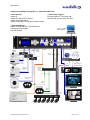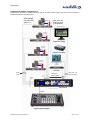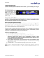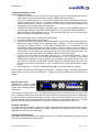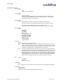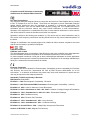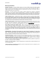
1
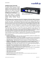
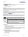
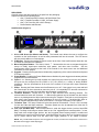
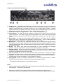
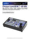
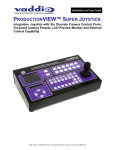
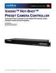
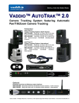
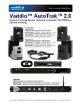
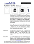
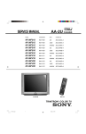
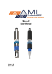
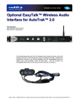
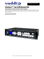
Installation and User Guide Camera and Electronic Products for Integrators VADDIO™ AUTOPRESENTER Automated Content Presentation System HD/SD Seamless Video Switching System with Video Transitions, Switchable PIP, Integration with the Vaddio AutoTrak and PresenterPOD Systems, Up/Down Converting of Inputs and Outputs and Preset PTZ Camera Control Model Number 999-5675-000 (NTSC) Model Number 999-5675-001 (PAL) ©2013 Vaddio - All Rights Reserved. AutoPresenter - Document Number 342-0029 Rev D Auto Presenter Inside Front Cover - Blank AutoPresenter Manual 342-0029 Rev D Page 2 of 28 Auto Presenter AutoPresenter Overview The Vaddio AutoPresenter is a six (6) input Automated Content Presentation System (ACPS™) and PTZ camera control system designed for a variety of presenter controlled applications with Vaddio’s preset camera trigger devices such as the MicVIEW™, StepVIEW™ mats, AutoVIEW™ IR Sensors, PresenterPOD™ and TouchVIEW™. Figure 1: The AutoPresenter The AutoPresenter can be used as a standAutomated Content Presentation System alone video switcher or seamlessly integrated with the Vaddio ProductionVIEW Precision Camera Controller and the amazing AutoTrak Presenter Tracking System. The AutoPresenter has 72 preset trigger inputs (138 total triggers accessible through RS-232 and through Multi-Step presets) and can automate any classroom or presentation environment, allowing a presenter or instructor to move about a classroom and switch up to six HD or SD video cameras, computer inputs or any other video source. Video transitions between sources include cuts, crossfades and a variety of wipes from .01 seconds to a full 4.0 seconds. First Step, Last Step or Multi-Step modes establish trigger priorities and allow for a preset shot to be assigned to two (2) separate triggers activated at the same time. PIP (Picture in Picture) is provided and can be arranged in five (5) different positions and in three (3) different sizes. PIP can be assigned to a camera shot preset and has independent sizing and positioning within each preset and is easily controlled with the very easy to operate Vaddio PresenterPOD System. The AutoPresenter’s multi-format 6 x 1 video switcher accepts any combination of input signals from HD YPbPr video (1080p, 1080i or 720p) or SD (Y/C & composite) and RGBHV (up to UXGA resolutions). All inputs can be scaled or converted to a single resolution (HD, SD or RGBHV up to WUXGA) on buffered dual outputs. Compatible PTZ cameras include Vaddio, Sony®, Panasonic® and Canon®. The AutoPresenter is an outstanding camera control system and is at the core of Vaddio’s Automated Content Presentation System technology. Applications for the AutoPresenter include videoconferencing, distance education, houses of worship, local government meetings and live event production. Key Technical Features: Seamless Video Switcher: When one of the six (6) input buttons is pressed, the seamless video switcher transitions from the current input to the new input. 72 Internal Trigger Presets: The console is equipped with automatic preset recall and camera switching when combined with Vaddio’s StepVIEW Mats, AutoVIEW IR, Presenter Pod, MicVIEW and other trigger devices, allowing AutoPresenter to be set up for use without an operator present. Additional Presets: Additional presets can also be stored from our Precision Camera Controller (14 presets per camera) making AutoPresenter extremely flexible in a variety of installation options. Anything In - Anything Out: The inputs and output have discrete video resolution settings. See the specifications at the end of the manual for additional information on all of the resolutions supported. Dual Outputs: Dual outputs (same resolution) can be run to separate devices that will accept an analog video signal, often avoiding the need for a distribution amplifier. Tally Ports: The AutoPresenter also has six Tally ports for controlling tally lights on external sources, such as Vaddio’s WallVIEW CCUs and PreVIEW HD monitors. Camera Auto-Sensing: The AutoPresenter is capable of auto-sensing each PTZ camera attached. Control codes for the following cameras are built-in: Vaddio PowerVIEW HD-22, and HD- 30 PTZ Cameras and all WallVIEW Packages using he HD-22 or HD-30 Vaddio ClearVIEW HD-18, HD-19,HD- 20 PTZ Cameras Vaddio WallVIEW, CCU and PRO Series Cameras Vaddio CeilingVIEW Series Cameras Vaddio HideAway Series Cameras Vaddio Model Series (Sony only) and PTZCam Series Cameras Sony EVI-HD1, EVI-HD-3& HD7V, EVI-100V, EVI-100S, EVI-D100, EVI-D70, BRC-300, BRC-Z330, BRC-Z700 & BRC-H700 Panasonic AW-HE100, AW-HE120 Canon XU-80, XU-81, BU-45,BU-46, BU-47H, BU-50, BU-51 AutoPresenter Manual 342-0029 Rev D Page 3 of 28 Auto Presenter Key Technical Features (continued): Video Transitions - Video transitions are seamless with exceptional video quality. Transition time is adjustable from zero (0) to four (4) seconds and include: Mix Cut Wipe (11 different patterns) Intended Use: Before operating the Vaddio AutoPresenter, please read the entire manual thoroughly. The system was designed, built and tested for use indoors, and with the provided power supply and cabling. The use of a power supply other than the one provided or outdoor operation has not been tested and could damage the camera and/or create a potentially unsafe operating condition. Save These Instructions: The information contained in this manual will help you install and operate your Vaddio AutoPresenter. If these instructions are misplaced, Vaddio keeps copies of Specifications, Installation and User Guides and most pertinent product drawings for the Vaddio product line on the Vaddio website. These documents can be downloaded from www.vaddio.com free of charge. Important Safeguards: Read and understand all instructions before using. Do not operate any device if it has been dropped or damaged. In this case, a Vaddio technician must examine the product before operating. To reduce the risk of electric shock, do not immerse in water or other liquids and avoid extremely humid conditions. Use only the power supply provided with the AutoPresenter system. Use of any unauthorized power supply will void any and all warranties. Do not use “pass-thru” or “EZ” type connectors. These connectors do not work well for professional installations and can be the cause of intermittent connection which causes most every control line (RS-232 or RS-422) in the integration world to fail. Please use standard RJ-45 connectors for best results, and test all cables for proper pin-out prior to termination. And finally, always read the manuals. Care and Cleaning Do not attempt to take this product apart at any time. There are no user-serviceable components inside. Do not spill liquids in the AutoPresenter Keep this device away from food and liquid. For smears or smudges on the console, wipe with a clean, soft cloth with a light duty household cleaner that leaves no residue. Repeated use of a “Windex®” type product with vigorous pressure may remove some of the silk screening and this will void the warranty. Do not use any abrasive chemicals. Operating and Storage Conditions: Do not store or operate the AutoPresenter under the following conditions: Temperatures above 40°C (104°F) or temperatures below 0°C (32°F) High humidity, condensing or wet environments or In inclement weather Dusty environments Under severe vibration AutoPresenter Manual 342-0029 Rev D Page 4 of 28 Auto Presenter UNPACKING: Carefully remove the device and all of the parts from the packaging. Unpack and identify the following parts: One (1) AutoPresenter Enclosure and Rack Mount Ears One (1) Vaddio PowerRite 12 VDC, 3A Power Supply One (1) AC Cord Set (US or UK & Europe) Documentation and Manuals AutoPresenter (Figure 2): ⑩ ① ② ③ ④ ⑤ ⑨ ⑧ ⑦ ⑥ 1. 8-Line LCD Screen (for Menus and Status): The internal menu allows the user to configure the resolution on the inputs/outputs, as well as other parameters built into the console. The LCD screen will also provide status to current settings. 2. IR Window: Pointing the supplied IR remote control at the front of the AutoPresenter allows the user to control the functions from a distance. 3. Menu Navigation Buttons: The Select, Cancel, , buttons allow the user to navigate through the menus to modify input/output resolutions, wipe pattern, and other menu functions. See the AutoPresenter Menu Structure at the back of the manual for the entire menu tree and additional information on menu options. 4. Program: Pressing the Program button initiates the programming of the camera selection and preset PTZ camera positions. 5. Preset Disable: Pressing the Preset Disable button disables all preset triggers and camera positions programmed into AutoPresenter. 6. Inputs 1 - 6: Selecting an input will transition the output from the current input to the one selected. All inputs can be configured as SD (CVBS or Y/C), HD (YPbPr) or a variety of analog RGBHV resolutions. See the specifications at the end of the manual for all input and output resolutions supported. 7. Power: Pressing the Power button turns AutoPresenter on or off. If the system is on, press and hold the Power button for three seconds to power the unit off. All compatible PTZ cameras connected to the system will go into stand by mode when AutoPresenter is powered off. 8. Transition Selection: Choose from Cut, Fade or Wipe transition when switching cameras. The selected transition button will illuminate. 11 different wipe patterns can be selected from the internal menu or by holding down the Wipe button and turning the Transition Time knob to scroll through the wipe options (wipe pattern options will be displayed on the LCD screen). Transitions (Mix, Wipe or Cut) can also be changed through either the IR remote, or through a third-party control system. 9. Transition Time: The rotary encoder will select the speed of the transition – from 0.1 to 4.0 seconds for both the Fade and Wipe transitions. Transition speed can also be adjusted from either the IR remote or through a third-party control system. 10. First, Last and Multi Step: When AutoPresenter is used with trigger devices (such as StepVIEW Mats), First Step mode keeps a camera fixed on the “first” triggered preset camera position. In Last Step mode, with multiple trigger devices, the “last” triggered preset camera position is recalled and switched as the output from AutoPresenter. Multi Step allows any two of the first 12 triggers to be set up for preset camera shots that will allow both trigger positions to be visible on-camera. NOTE: Only one MicVIEW microphone can be triggered at one time, therefore two microphones connected to a MicVIEW cannot trigger a Multi Step trigger. AutoPresenter Manual 342-0029 Rev D Page 5 of 28 Auto Presenter AutoPresenter Back Panel I/O (Figure 3): ⑪ ⑫ ⑬ ⑭ ⑳ ⑲ ⑮ ⑯ ⑰ ⑱ 11. Trigger Inputs 1 – 24 and Trigger Inputs 25 – 72: The first 24 trigger inputs are on Phoenix-type connectors. Trigger inputs 1 – 12 can be programmed in First Step, Last Step and Multi Step operation, which allows the live camera to zoom in or out to multiple trigger positions. Supports Vaddio AutoVIEW IR, StepVIEW, TouchVIEW, MicVIEW and PresenterPOD trigger inputs as well as 3rd party control devices. Trigger inputs 25 - 72 are on two 25-pin connectors. 12. Power Input: AutoPresenter operates on 12 VDC, 3 Amp PowerRite power supply. 13. Control Inputs: For each PTZ camera connected, a homerun CAT-5 cable is run to the RS-232 input of the camera. This allows the pan, tilt and zoom position to be sent to the camera for preset camera positions. If the input is not a PTZ camera (DVD player, computer, etc.), then this port is not used. 14. Video Inputs: The video inputs can accept the SD (composite or Y-C), HD (Y, Pb, Pr) or RGBHV signals (each input is independent and selectable via internal menu). See the Video Resolutions table at the back of the manual for all supported input/output video signals. 15. RS-232 Thru: The RS-232 Thru connection allows the user to send RS-232 signaling through AutoPresenter to other control equipment, such as third-party control systems (available on a future release of firmware) and allows the AutoPresenter to supply the AutoTrak IR Tracking System with up to six (6) total presets. 16. RS-232: The RS-232 input allows the AutoPresenter to receive commands from third-party hardware. This port is also used as a connection for updating firmware on the system. 17. Program Outputs: Delivers the same SD (composite or Y-C), HD (Y, Pb, Pr) or RGBHV signal (selectable via internal menu) on both connectors. See the Video Resolutions table at the back of the manual for all supported input/output video signals. 18. Link In / Link Out: The Link In / Link Out connectors allow AutoPresenter to seamlessly integrate with Vaddio’s Precision Camera Controller, when used as an operator controlled seamless switcher. 19. *Network: The Network port is a 10/100 mbps Ethernet port to allow remote access of the system for troubleshooting and status (available on a future release of firmware). 20. Tally Outputs: Allows for connecting AutoPresenter to external Tally inputs such as Vaddio’s PreVIEW HD monitors, Quick-Connect CCU and other third-party tally sources. * The Network port will be active on a future software release. Notes: Vaddio accessory cables for SD (NTSC or PAL composite video) and HD/SD component (YPbPr) are sold separately. (Part Number 440-5600-000) Strain relief for the DE-15 (15-pinHD) connectors is highly recommended on the back of the AutoPresenter for permanent installations to ensure that the cables do not negatively affect the PCB. AutoPresenter Manual 342-0029 Rev D Page 6 of 28 Auto Presenter AutoPresenter IR Remote Control 1) Power: Pressing the Power button will turn the system on. Press and hold the Power button for 3 seconds to turn on or off the system. ⑥ 2) Transition Select: Pressing the up or down button will switch the type of transition from wipe, fade or cut. The wipe that is currently selected via the internal menu will be the wipe transition that occurs. ① ⑦ ② ⑧ 3) Preset Control: Use the 0-9 buttons to program and recall preset camera positions. Preset Disable turns off all presets camera positions that are programmed into the system. ③ 4) Zoom: Press the in and out buttons for zoom control of the selected PTZ camera. ⑨ 5) PIP (picture-in-picture): PIP ON/OFF, PIP Position and PIP Size are adjusted with these controls. 6) Priority: Pressing First, Last or Multi buttons will choose the Step function for the input triggers on the system. Inputs 1-12 are multi-step triggers. All other triggers in Multi-Sep mode will act as Last Step. 7) Program: Pressing the Program button initiates the program feature of the system, allowing the PTZ camera positions and inputs to be selected. ④ ⑩ ⑤ ⑪ 8) Transition Time: Pressing the up and down will increase or decrease the transition time from 0.1 to 4 seconds for wipe or fade transitions. 9) Preset Disable: This turns off all presets camera positions that are programmed into the system. 10) PTZ Camera: These buttons move the pan and tilt of the selected camera. Pressing the Home button moves the PTZ camera to the home position. 11) Input Select: Pressing the 1-6 buttons selects which input will be sent to the outputs. Figure 4: AutoPresenter IR Remote Control AutoPresenter Manual 342-0029 Rev D Page 7 of 28 Auto Presenter Operating the PIP: The PIP (picture-in-picture) can be accessed via RS-232 or with the IR Remote control. For RS-232, see the attached API in Appendix 1. Figure 5: IR Remote To operate the PIP with the IR remote control, perform the following steps: 1) Chose a background input by selecting 1 through 6 on the INPUT SELECT buttons. 2) Press the PIP ON/OFF Button and then press an INPUT SELECT button other than the input selected as the background. The PIP will appear in the foreground layer as a PIP. 3) To change the size of the PIP, press the PIP SIZE button and the PIP size will cycle through three (3) PIP sizes (small, medium & large). 4) To change the position of the PIP, press the PIP POS button and the PIP will cycle through the available positions clockwise. 5) To turn off the PIP press the PIP ON/OFF button and the PIP will close. PIP Controls Input Select Buttons AutoPresenter “Content Plus” PIP Trigger Feature: The Content Plus feature is a unique feature that allows the presenter to select background shots while retaining the original PIP window. This works by selecting a background (like a PC input or Video White Board) selecting a PIP input. The next input selected will momentarily move the PIP to full screen, switch the background and then restore the PIP to the previous size and position with a different background. AutoPresenter with Built-in PresenterPOD Support The Vaddio Presenter Pod System (consisting of the PresenterPOD and Pod Interface) is a unique presenter control device that employs three trigger outputs and an ultrasonic presenter sensor that allows any presenter to easily control the content in the meeting as well as turn On/Off the PIP video within any AutoPresenter preset. To assign a PIP Trigger number: 1) From the main menu scroll down until the PIP Trigger Menu is shown, touch the Select key. 2) The PIP trigger can be assigned to Triggers 1 through 24. Scroll to the number you have selected for the PIP trigger for PIP On/Off and touch Select. The type or mode of the trigger can also be selected in order to work with momentary or latching trigger products. After selecting a PIP Trigger number: 1) From the main menu scroll to the PIP Trigger Mode and touch select. 2) Choose between the two (2) options, Momentary of Latched, and touch select. The AutoPresenter is now configured for PIP On/Off with the trigger number assigned and the trigger type assigned. Please see the PresenterPod and other Vaddio triggering products for additional information. AutoPresenter Manual 342-0029 Rev D Page 8 of 28 Auto Presenter Accessories for AutoPresenter Vaddio Accessory Cable Part Numbers Part Number Description 440-5600-000 DE-15 to Std. Definition Video (CVBS & Y/C) breakout cable with female BNC connectors 440-5600-001 DE-15 to HD/SD Component (YPbPr/RGBHV) cable with male BNC connectors 440-5600-002 DE-15 to HD/SD Component (YPbPr/RGBHV) cable with male BNC connectors 440-5600-003 DE-15 to HD/SD Component (YPbPr/RGBHV) cable with female BNC connectors Vaddio Presence Sensing Trigger Devices Part Number Description StepVIEW Mat 44” x 27.5” with 75’ 999-1511-000 attached cable 999-1512-000 StepVIEW Mat 57” x 27.5” with 75’ attached cable 999-1701-100 AutoVIEW IR Sensor, interface controller, cable and power supply 999-1111-000 North America PresenterPOD Automatic Ultrasonic Presenter Sensor and Manual Preset Trigger Device for the Vaddio AutoPresenter 999-1111-001 International Length 1’ (30.5cm) Picture 3’ (.914m) 6’ (1.83m) 7” (21.3cm) Picture Vaddio MicVIEW Microphone Switcher and Trigger Devices Part Number Description Picture 999-0001-000 MicVIEW - 12 input Mic North America Switcher/Mixer 999-0001-001 International AT Unidirectional Boundary 701-0001-891 Microphone 3-wire Push-to-Talk 999-1201-000 TouchVIEW System with 4 RF buttons & 1 Receiver AutoPresenter Manual 342-0029 Rev D Page 9 of 28 Auto Presenter Set-up and Programming First Time Set-up with the AutoPresenter: AutoPresenter was designed to be exceptionally easy to program and use. All of the Vaddio standards for transmitting RS-232 control over Cat. 5 cabling are in this manual and available free of charge from the Vaddio website. Getting Started: 1. Connect all of the cameras, monitors and peripheral devices to AutoPresenter. The back panel has standard VGA connectors, and Vaddio offers four different break out cables for the inputs/outputs; one for SD video (composite on inputs & outputs, Y-C also on inputs) and three cables (7 in., 3 ft. or 6 ft.) for component HD/SD video (YPbPr). 2. When applicable, connect the RS-232 port on the AutoPresenter to an available serial port on a control system (i.e. Crestron®, AMX®, etc.). 3. Trigger Devices: Connect wires from the trigger devices (i.e. StepVIEW mat, AutoVIEW IR, MicVIEW, etc.) to each designated port. One wire will go to the trigger input and the other will go to one of the “G” (Ground) ports. See the specific trigger devices for additional information on installation. Make note as to what trigger device is connected to which specific trigger port on the back of AutoPresenter. NOTE: The dual outputs Video Outputs of the AutoPresenter will deliver the same resolution. Once all of the inputs, outputs, trigger devices and the PowerRite power supply are connected, plug the AC cord into an outlet. AutoPresenter will boot up and scan for cameras. After boot up, a menu will appear on the blue LCD screen. Configuring Output Resolutions On the LCD screen, a chevron (>) will be displayed next to the menu item that is currently selected. Press the Arrow Down Button (↓) adjacent to the LCD screen, until the chevron is next to “VIDEO OUTPUT MENU” and then press the SELECT button. Arrow down to the appropriate resolution that is compatible with your video monitor, then press the SELECT button. Then, press the CANCEL button to exit to the previous menu. AutoPresenter V01.02.00 MAIN MENU >Rescan Cameras Rescan Video Video Output Video Input Menu <Status Line> NOTE: For additional information on the menu structure, see pages 17 through 20 Configuring Input Resolutions From the Main Menu, press the down arrow button, to move the chevron to VIDEO INPUT MENU, and then press the SELECT button. If all input devices have the same resolution (i.e. 1080i / 59.94), then select ALL PORTS. If not all inputs have the same resolution, then press the down arrow button to the first input with a video device attached, and press SELECT. Choose the appropriate video resolution for the video device connected to the input, and then press SELECT. Press the CANCEL button to exit the resolution setting for the input. Repeat the process for all video inputs. After all inputs/outputs have been set, touch the arrow up to RESCAN VIDEO. Press SELECT. At START press SELECT again. All video resolutions will now be configured. Any time an input or output source is changed you will need to perform the RESCAN VIDEO function for the new settings. Configuring PTZ Cameras After configuring the input and output resolutions, arrow down to, and select CAM SEARCH MENU on the LCD screen. Arrow down to PORT 1 and press select. Next, select the type of camera that is connected to Port 1 (i.e. if a Canon PTZ camera is connected, select CANON ONLY). Repeat the process for each port, based on the type of camera that is connected. For Vaddio PTZ cameras, select AUTO SEARCH. NOTE: If no PTZ camera is connected to specific Control Ports, select “No Camera” in the “Cam Search Menu” to speed up the boot-up process. AutoPresenter Manual 342-0029 Rev D Page 10 of 28 Auto Presenter AutoPresenter Sample Configuration 1: Automated Classroom • Video Sources: Laptop PC Vaddio HD-18W HD PTZ Camera Vaddio Video White Board Vaddio CeilingVIEW HD Ceiling Document Camera • Video Preset Triggers: PresenterPODs (2) - 10 triggers total MicVIEW with six (6) Push to Talk Mics • Video Destinations: Vaddio PreVIEW HD Dual 7.0 Rack Monitors Videoconferencing System Dual HD Monitors WallVIEW HD-18W Laptop PC - RGBHV 1280x768@60Hz HD Video 1080P/60 & Control Quick-Connect Near End HD Video RGBHV QuickConnect Preset Triggers Teacher Camera Quick-Connect LAN CAT 5e HD Video, Power and Control WallVIEW HD-18W T C60 Codec Far End HD Video Audio PreVIEW HD Monitors HD Video, Power and Control Student Camera PresenterPOD Interface 2-Pods Supported CAT 5e Far End HD Video CAT 5e CAT 5e HD Video, Power and Control Trigger Data CeilingVIEW HD Over Lectern PresenterPOD at Front Lectern ? PresenterPOD at Video Whiteboard Near End HD Video Trigger Data MicVIEW Mic Switcher/Mixer Audio Out Simulated Video Feeds Electronic WhiteBoard Push to Talk Microphones Assigned to Camera Presets AutoPresenter Manual 342-0029 Rev D Page 11 of 28 Auto Presenter AutoPresenter Sample Configuration 2: AutoPresenter connected to Vaddio’s Precision Camera Controller via the Vaddio Link control bus and used as a Professional operator controlled system. Vaddio WallVIEW CCU H700 Camera Systems x 4 Video, Power and Control on CAT 5e Up to 500’/154.2m Simulated Video Feeds Video, Power And Control Video, Power And Control Video, Power And Control RS-232 Control Video Inputs: HD, SD, RGBHV Video Outs - HD Same Resolution AutoPresenter AutoPresenter Manual 342-0029 Rev D Page 12 of 28 Auto Presenter Controlling the AutoPresenter Functions and controls on the front panel are easy and intuitive. Over the next few pages there are details on how the different functions operate, as well as how to program the inputs, outputs and trigger devices connected to AutoPresenter. PTZ Camera Controls: The controls that can be used to program presets, switch inputs, adjust a PTZ camera can be found on the Vaddio AutoPresenter IR remote control supplied with the product (see remote on p.6). Preset Location Storage Options: This feature allows the user to store 72 First Step/Last Step camera presets in the AutoPresenter on up to six PTZ cameras. Any number of presets can be stored on any number of cameras (i.e. 72 presets can be stored on one camera, 24 presets on three cameras, etc.). Please see the AutoPresenter Menu Structure, System Menu for access to the Preset location parameter. Before Programming Preset Camera Positions: Make note of all preset trigger devices connected to AutoPresenter, and which presets will trigger which devices. For instance, if there are four StepVIEW mats at the front of a lecture hall – two at whiteboards, one at a podium and one at a document camera – note which presets each mat will trigger. If there are additional trigger devices, such as microphones connected to Vaddio’s MicVIEW product, then make a note of which presets are assigned to which triggering device. There are two ways to program presets into the AutoPresenter; either by activating each trigger installed in the system, or through the AutoPresenter IR remote control. Knowing the preset associated with each trigger will allow all programming to happen through the remote control. For this manual, all preset programming described, will be handled through the IR remote control. Setting First Step/Last Step Presets 1. Press the Program button on the front of AutoPresenter 2. Confirm that either the First Step or Last Step button above Program is illuminated 3. Select the camera to program (Inputs 1 to 6) on the front panel of AutoPresenter 4. Using the AutoPresenter IR remote, pan, tilt and zoom the camera to the desired location for the specific preset camera position. Example: If there is a StepVIEW mat (connected to Trigger position 1 on the back of AutoPresenter) at a whiteboard, frame the camera to capture the area of the whiteboard visible above the StepVIEW mat. 5. Press 001 on the IR remote control. The LCD screen on the front of AutoPresenter will display “Preset 1 Stored”. The other way for storing the preset camera position would be to manually trigger the device that will move the camera to that position. See note below about numbering scheme for trigger presets. 6. Repeat the Steps 2 – 4 for each additional preset trigger device connected to the system. NOTE: Please note that each preset trigger is three digits. Therefore, trigger 1 should be programmed and recalled on the IR remote by pressing 001. Trigger 23 would be recalled by pressing 023 on the remote. AutoPresenter Manual 342-0029 Rev D Page 13 of 28 Auto Presenter Configuring Multi-Step Presets Notes Regarding Multistep: Multi-Step is available only on the first 12 preset trigger inputs on AutoPresenter and allows a camera preset to be programmed into the system to display two trigger devices. If there are multiple cameras in a room and the triggers that activate Multi Step are linked to different cameras, either camera, or a different camera can be programmed as the Multi Step camera preset position to allow the camera with the best angle of view of both positions to be configured for the multi-step preset camera position. Two MicVIEW triggers cannot trigger a multi-step trigger, however, a single MicVIEW trigger and another trigger device (i.e. StepVIEW mat, AutoVIEW IR, etc.) can perform a Multi-Step preset. Multi-Step with a trigger outside the first 12: with one preset within the first 12, and one preset that is 13 or higher, Last Step will be initiated. 1. Press the Program button on the front of AutoPresenter 2. Press the Multi Step button above Program 3. Using the AutoPresenter IR remote, pan, tilt and zoom a camera to the desired location that will capture both trigger positions for the multi-step trigger. Example: If there is a StepVIEW mat (connected to Trigger position 1 on the back of AutoPresenter) at a whiteboard, and an AutoVIEW IR sensor (connected to Trigger position 12) above a podium, move a camera to capture both the whiteboard and podium. Any camera in the room may be used for the multi-step preset position, not necessarily the camera(s) that are used for the First/Last Step preset. Use the best camera that will provide the ideal camera angle for the multi-step preset. 4. Using the IR remote, enter the two preset trigger devices. From the example above – preset triggers 1 and 12, enter 001 and 012 using the remote control. The LCD screen on the front of AutoPresenter will display “Preset XX Stored”, with XX being the designated stored preset. The other option for storing the preset camera position would be to manually trigger the devices that will move the camera to that position. See note below about numbering scheme for trigger presets. 5. Repeat the Steps 2 – 4 for each additional preset trigger device connected to the system. NOTE: Please note that each preset trigger is three digits. Therefore, trigger 1 should be programmed and recalled on the IR remote by pressing 001. Trigger 23 would be recalled by pressing 023 on the remote. Wipe, Dissolve or Cut AutoPresenter allows camera transitions to be either a cut, fade or wipe when switching between video inputs. Select the type of effect (wipe, cut or mix) that AutoPresenter will use to transition from one input to the other. Pressing a different input, other than the current input that is selected (current input is indicated by the button being lit) will allow AutoPresenter to transition from the current signal to the one selected. The transition between inputs will be determined by which transition is selected (Mix, Wipe or Cut), and the speed of the transition will be dictated by the Transition Time knob on the front of the switcher. Changing Transitions: To change the type of transition -- Wipe, Cut or Mix -- select that effect above the Input buttons. Wipes: Press and hold the Wipe button and turn the Transition Speed knob to change wipe effects, which will be displayed at the bottom of the LCD screen. Changing Transition Speed: Both the Mix and Wipe effects can be adjusted from .01 to 4 seconds, by adjusting the Transition Speed knob, which is located next to the Mix button. AutoPresenter Manual 342-0029 Rev D Page 14 of 28 Auto Presenter Power & Preset Disable If AutoPresenter is configured to be used as an automated, presenter controlled system, StepVIEW mats, AutoVIEW IR sensors and other devices, the mats, sensors and third-party trigger devices can be placed at locations, such as podiums, white boards, etc. Pressing the Preset Disable button on the front panel or via the IR remote control will disable all trigger devices (StepVIEW mats, AutoVIEW IR sensors, etc.). Power Switch: When the Power switch is pressed and held for three seconds, all of the attached cameras will be placed in standby. When the system is in stand-by, pressing the Power switch will activate and select default camera and preset information as defined in the menu. The AutoPresenter will scan the inputs for camera type and video signal type and configure the system based on how it was programmed. This can take up to one minute and is normal operation. Notes: When the camera control ports are changed or reconfigured, the “Rescan Cameras” option in the menu must be selected and started to rescan the cameras and reload the proper control codes. If only the video inputs are changed, then activate the Rescan Video function in the Main Menu to reset the video input priorities. Notes: If new triggers are added or not connected at initial power up you must perform an INIT TRIGGERS in the system menu. Using AutoPresenter with Precision Camera Controller AutoPresenter can also be used as a stand-alone switcher (with or without triggers) connected to Precision Camera Controller as a low-cost, 6x1 seamless video switcher for installations that require an operator for some events, but automated operation for other events. Figure 4 shows 6 inputs (four cameras, a computer and a DVD player) and two outputs (a computer monitor and an LCD projector). Simply connect the Link Out port of Precision Camera Controller to the Link In port on AutoPresenter to establish communication between the two products (see the diagram below). CAT-5 Cable LINK OUT LINK IN Note: See Figure 4 for a more detailed wiring diagram Configuring PTZ Presets for Precision Camera Controller: NOTE: Presets for Precision Camera Controller are stored in memory beyond the presets for the trigger devices connected to AutoPresenter, and have to be programmed separately. All RS-232 Control cables for PTZ cameras should be connected to AutoPresenter. When using Precision Camera Controller, the PRESET DISABLE button should be turned on. Otherwise, trigger devices connected to AutoPresenter will initiate PTZ cameras and video switching. AutoPresenter Manual 342-0029 Rev D Page 15 of 28 Auto Presenter AutoPresenter Menu Structure: The AutoPresenter has an 8-line LCD that displays the system menus. The menus are navigated with the up/down arrows, select and cancel buttons. The menu structure is as follows: st 1 Screen Menu Section AutoPresenter V01.02.0x (software version) MAIN MENU Rescan Cameras Rescan Video Video Output Video Input Menu <Status Line> Rescan Cameras >Select (Note: Rescans all RS-232 ports for auto sensing camera type and loads control protocols) >Start Rescan Video >Select (Note: Resets all inputs, outputs and video processors) >Start Video Output Menu (Note: Both video outputs will deliver the same output resolution) >Select >Video Output HD 1080p/59.94 Hz HD 1080p/50 Hz HD 1080i/59.94 Hz HD 1080i/50 Hz HD 720p/59.94 Hz HD 720p/50 Hz *HV 640 x 480 @60 Hz HV 800 x 600@60 Hz HV 1024 x 768@60 Hz HV 1280 x 768@60 Hz HV 1280 x 1024@60 Hz HV 1366 x 768@60 Hz HV 1400 x 1050@60 Hz HV 1600 x 1200@60 Hz HV 1920 x 1200@60 Hz SD NTSC 480i/29.97Hz Composite (CVBS and Y/C [dual out] with adapter cable 440-5600-000) SD PAL 576i/25Hz Composite (CVBS and Y/C [dual out] with adapter cable 440-5600-000) SD NTSC 4801i/29.97 YPbPr SD PAL 576i/25 YPbPr *HV is an abbreviation for RGBHV Video Input Menu >Select >All Ports - OR - Individual Ports - 1 through 6 HD 1080p/59.94 Hz HD 1080p/50 Hz HD 1080i/59.94 Hz HD 1080i/50 Hz HD 720p/59.94 Hz HD 720p/50 Hz HV 640 x 480 @60 Hz HV 800 x 600@60 Hz HV 1024 x 768@60 Hz HV 1280 x 768@60 Hz HV 1280 x 1024@60 Hz HV 1366 x 768@60 Hz HV 1400 x 1050@60 Hz HV 1600 x 1200@60 Hz SD NTSC - (S-Video) - 480i/29.97Hz with adapter cable 440-5600-000 SD PAL - (S-Video) - 576i/25Hz with adapter cable 440-5600-000 SD NTSC Composite - (4801i/29.97 with adapter cable 440-5600-000) SD PAL Composite - (576i/25 with adapter cable 440-5600-000) AutoPresenter Manual 342-0029 Rev D Page 16 of 28 Auto Presenter Menu Structure Continued SD Video Format >Select >Letter Box >Crop >Squeeze Enables the use of some SD signals to be mixed with HD video signals while avoiding aspect ratio problems Default Preset No Default Preset Number >Select > 01 – 72 Assigns camera preset 1 through 72 as Default Preset on the default camera (default is 01) Default Timer >Select >00 – 60 Default Camera Idle Return Timer - with no other trigger input, the system returns to the Default Camera and Default Preset after this time elapses (default is 10, 00 disables function) Preset Pan Speed >Select >01 – 24 (default is 18) Sets the Pan Speed on all cameras between camera presets (24 is fastest) Preset Tilt Speed >Select >01 – 20 (default is 15) Sets Tilt Speed on all cameras between camera presets (20 is fastest) Preset Zoom Speed >Select >00 – 07 (default is 04) Sets Zoom Speed on all cameras between camera presets (06 is fastest Cam Search Menu >Select >All Ports: (select search method – Auto, Sony, Canon, Panasonic, No Camera Input) >Port 01: (select search method – Auto, Sony, Canon, Panasonic, No Camera Input) >Port 02: (select search method – Auto, Sony, Canon, Panasonic, No Camera Input) >Port 03: (select search method – Auto, Sony, Canon, Panasonic, No Camera Input) >Port 04: (select search method – Auto, Sony, Canon, Panasonic, No Camera Input) >Port 05: (select search method – Auto, Sony, Canon, Panasonic, No Camera Input) >Port 06: (select search method – Auto, Sony, Canon, Panasonic, No Camera Input) NOTE: When using Panasonic cameras, you must select Panasonic. If there is no camera connected to the control port of an input, selecting No Camera Input will lower the time of the boot-up process by not scanning for a camera on those selected inputs. System Menu >Select >Serial Input >Select >ON or OFF Turns on or off serial input (default is ON). >Serial Echo >Select > ON or OFF Turns Serial Echo on or off (default is ON). >Serial Info >Select > ON or OFF Reports button pushes on front panel to the serial port (default is OFF). >Panel Lights >Select >00 through 50 Panel Light Brightness (all lights - 50 is the brightest) (default is 25, off is 00). >Clear Memory >Select >Start Clears the camera preset memories and sets all parameters to default settings. AutoPresenter Manual 342-0029 Rev D Page 17 of 28 Auto Presenter System Menu (continued) >Clear Presets >Select >Start Clears only the camera presets >Transition Time >Select >0.1 to 4.0 Seconds Allows user to adjust transition time from menu or through RS-232 (i.e. control systems) Transition Time is also adjustable from front panel and can be stored in the presets if the Transition Mode (below) is set to “By Preset”. >Transition Mode >Select >Global (default) - Transitions and Times are the same for every video switch. >By Preset - allows user to set up different Transitions and Times between video switch. The currently selected transition will switch cameras in Global mode. In “By Preset” mode, the selected transition when a preset is stored will be the transition. >Wipe Selection >Select Right to Left Left to Right Top to Bottom Bottom to Top Down Right to Upper Left Down Left to Upper Right Upper Right to Down Left Upper Left to Down Right All Sides to Center Left>Center<Right Top>Center<Bottom >Settle Time >Select NOTE: TIP: >0.10 to 0.90 seconds (Default is 0.20) Settle time allows the user to set up the time delay between switching from one input to another. With a lower settle time, there is a greater chance that video will glitch on the Preview outputs when the video is switched very quickly, and repeatedly in such a way and speed that is not really practical. In most applications this is not an issue. To avoid the dastardly video glitch or transient hiccup, use the same resolution video feeds (all 1080i or all 720p on the inputs) and the settle time (the time it takes to acquire the signal, stabilize the video, route the signal and scale the signal, process it and send it to the program output) can be reduced for a very quick, glitch free production which is ideal for a 3-camera interview shoot using quick cuts, but if you are producing content such as this, you already know this tip. On the other hand, if you were to use all 6-inputs with different video resolutions and aspect ratios, expect to increase your settle time accordingly. >Tally >Select >Active High >Active Low (Default is Active Low) >Init Triggers >Start Note: Init Triggers must be performed when new trigger devices have been added after initial startup) >Preset 67-72 >Cam Presets On >Cam Presets Off Selects only the input port without moving the cameras on that port AutoPresenter Manual 342-0029 Rev D Page 18 of 28 Auto Presenter Menu Structure Continued AutoTrak Input >Select >0 - No AutoTrak Support >1 through 6 Identifies which input on the AutoPresenter to establish presets for the AutoTrak. RS-232 commands Can be sent from AutoPresenter to AutoTrak when an external trigger (StepVIEW, AutoVIEW IR, PresenterPOD, etc…) is received that references that video input port. Essentially, this feature allows the AutoTrak system to have 6 presets when used with the AutoPresenter. PIP Trigger >Select >1 through 24 Allows triggers 1 through 24 to turn the PIP stored within a preset ON/OFF - for use with Vaddio PresenterPOD or other triggering device PIP Trigger Mode >Select > MOMENTARY > LATCHED Allows user to select momentary (unlatched) trigger inputs or latched trigger inputs (trigger device dependent) Figure 9: AutoPresenter Back Panel with I/O Information AutoPresenter I/O Connectors Power: 12 VDC, 3A (5.5mm OD x 2.5mm ID) Video In 1-6: HD Component (Y, Pb, Pr), RGBHV, S-Video (Y-C) or Composite (DE-15 female x 6) Control In 1-6: RS-232C (RJ-45 F x 6) Video Out: HD or SD Component (Y, Pb, Pr), RGBHV or *Composite (NTSC or PAL) RS-232: DB-9F RS-232 THRU: DB-9 M Triggers (1-24): 14-pin Phoenix type connector (x2) Triggers (25-72): DB-25 F (x2) Tally Outputs: 7-pin Phoenix type connector Network: RJ-45 F (available in a future software release) Link In/Out: RJ-45 F (x2) For use with Precision Camera Controller Joystick *Note: 440-5600-000 DE-15 to SD (CVBS & Y-C) breakout cable with female BNC connectors is required for NTSC or PAL composite video AutoPresenter Manual 342-0029 Rev D Page 19 of 28 Auto Presenter Compliance and CE Declaration of Conformity AutoPresenter 6x1 Switcher/Mixer/Controller FCC Part 15 Compliance This equipment has been tested and found to comply with the limits for a Class B digital device, pursuant to Part 15, Subpart B of the FCC Rules. These limits are designed to provide reasonable protection against harmful interference when the equipment is operated in a commercial environment. This equipment generates, uses, and can radiate radio frequency energy and, if not installed and used in accordance with the instruction manual, may cause harmful interference to radio communications. Operation of this equipment in a residential area is likely to cause harmful interference in which case the user will be required to correct the interference at his/her own expense. Operation is subject to the following two conditions: (1) This device may not cause interference, and (2) This device must accept any interference including interference that may cause undesired operation of the device. Changes or modifications not expressly approved by Vaddio can affect emission compliance and could void the user’s authority to operate this equipment. ICES-003 Compliance ICES-003, Issue 4: 2004 This digital apparatus does not exceed the Class B limits for radio noise emissions from digital apparatus set out in the Radio Interference Regulations of the Canadian Department of Communications. Le présent appareil numérique n’emet pas de bruits radioélectriques dépassant les limites applicables aux appareils numeriques de la classe B préscrites dans le Règlement sur le brouillage radioélectrique édicte par le ministère des Communications du Canada. European Compliance This product has been evaluated for Electromagnetic Compatibility under the standards for Emissions and Immunity and meets the requirements set forth by EMC Directive 2004/108/EC for an E4 environment. In a domestic environment this product may cause radio interference in which case the user may be required to take adequate measures. Standard(s) To Which Conformity Is Declared: EMC Directive 2004/108/EC EN 55103-1: 1996, Electromagnetic Compatibility - Emissions EN 55103-2: 1996; E4-Controlled EMC Environment - Electromagnetic Compatibility - Immunity EN 61000-3-2: 2006 - Limits for Harmonic Current Emmissions EN 61000-3-3: 1995 + Amendment A1: 2001 + A2: 2005 - Limitation of Voltage Changes & Fluctuations EN 61000-4-2: 1995 + Amendments A1: 1998 + A2: 2001 - Electrostatic Discharge EN 61000-4-3: 2002 - Radiated Immunity EN 61000-4-4: 2004 - Electrical Fast Transients EN 61000-4-5: 1995 + Amendment A1: 2001 - Surge Immunity EN 61000-4-6: 1996 + Amendment A1: 2001 - Conducted Immunity EN 61000-4-11 Second Edition: 2004 - Voltage Dips, Interrupts and Fluctuations Annex A of EN 55103-2: 1996 - Magnetic Field Immunity AutoPresenter Manual 342-0029 Rev D Page 20 of 28 Auto Presenter Warranty Information: Hardware* Warranty - One year limited warranty on all parts. Vaddio warrants this product against defects in materials and workmanship for a period of one year from the day of purchase from Vaddio. If Vaddio receives notice of such defects during the warranty period, they will, at their option, repair or replace products that prove to be defective. Exclusions - The above warranty shall not apply to defects resulting from: improper or inadequate maintenance by the customer, customer applied software or interfacing, unauthorized modifications or misuse, operation outside the normal environmental specifications for the product, use of the incorrect power supply, improper extension of the power supply cable or improper site operation and maintenance. Vaddio Customer service – Vaddio will test, repair, or replace the product or products without charge if the unit is under warranty and is found to be defective. If the product is out of warranty, Vaddio will test then repair the product or products. The cost of parts and labor charge will be estimated by a technician and confirmed by the customer prior to repair. All components must be returned for testing as a complete unit. Vaddio will not accept responsibility for shipment after it has left the premises. Vaddio Technical support - Vaddio technicians will determine and discuss with the customer the criteria for repair costs and/or replacement. Vaddio Technical Support can be contacted through one of the following resources: e-mail support at [email protected] or online at www.vaddio.com. Return Material Authorization (RMA) number - Before returning a product for repair or replacement, request an RMA from Vaddio’s technical support. Provide a technician with a return phone number, email address, shipping address, and product serial numbers and describe the reason for repairs or returns as well as the date of purchase and proof of purchase. Include your assigned RMA number in all correspondence with Vaddio. Write your assigned RMA number on the outside of the box when returning the product. Voided warranty – The warranty does not apply if the original serial number has been removed or if the product has been disassembled or damaged through misuse, accident, modifications, or unauthorized repair. Cutting the power supply cable on the secondary side (low voltage side) to extend the power to the device (camera or controller) voids the warranty for that device. Shipping and handling - Vaddio will not pay for inbound shipping transportation or insurance charges or accept any responsibility for laws and ordinances from inbound transit. Vaddio will pay for outbound shipping, transportation, and insurance charges for all items under warranty but will not assume responsibility for loss and/or damage by the outbound freight carrier. • If the return shipment appears damaged, retain the original boxes and packing material for inspection by the carrier. Contact your carrier immediately. Products not under warranty - Payment arrangements are required before outbound shipment for all out of warranty products. *Vaddio manufactures its hardware products from parts and components that are new or equivalent to new in accordance with industry standard practices. AutoPresenter Manual 342-0029 Rev D Page 21 of 28 Auto Presenter Video Resolutions Supported* Input Signal Formats Supported Resolutions YPbPr 720p 59.94/50 1080i 59.94/50 1080p 59.94/50 RGBHV 640 x 480 @ 60Hz - VGA 800 x 600 @ 60Hz - SVGA 1024 x 768 @ 60Hz - XGA 1280 x 768 @ 60Hz - WXGA 1280 x 1024 @ 60Hz - SXGA 1366 x 768 @ 60Hz - WXGA 1400 x 1050 @ 60Hz - SXGA+ 1600 x 1200 @ 60Hz - UXGA Std Definition - w/Adapter 480i/29.97 Cable (Y/C or CVBS) 576i/25 Output Signal Formats Supported Resolutions YPbPr 720p 59.94/50 1080i 59.94/50 1080p 59.94/50 480i/29.97 576i/25 RGBHV 640 x 480 @ 60Hz - VGA 800 x 600 @ 60Hz - SVGA 1024 x 768 @ 60Hz - XGA 1280 x 768 @ 60Hz - WXGA 1280 x 1024 @ 60Hz - SXGA 1366 x 768 @ 60Hz - WXGA 1400 x 1050 @ 60Hz - SXGA+ 1600 x 1200 @ 60Hz - UXGA 1920 x 1200 @60 HZ - WUXGA* *With reduced blanking Std Definition 480i/29.97 w/Adapter Cable (Y/C 576i/25 and CVBS) Aspect Ratio ALL 16:9 4:3 4:3 4:3 15:9 5:4 16:9 4:3 4:3 4:3 4:3 Aspect Ratio 16:9 16:9 16:9 4:3 4:3 4:3 4:3 4:3 15:9 5:4 16:9 4:3 4:3 16:10 4:3 4:3 Support of 1080p component video (YPbPr) required on third-party equipment *Certain equipment may not be capable of all the resolutions listed and therefore may not function properly. If a certain resolution does not seem to work appropriately, please make sure that the displaying device or PC is properly configured, is capable of the resolution that is chosen and is cabled correctly. Often times a laptop PC will not output the same resolution that it displays on a its own LED, and on top of that, the resolution between the laptop PC and attached LCD screen does not use a VESA recognized resolution. Furthermore, just because a resolution is listed on the table in this manual and in the AutoPresenter menu, does not mean the display device can reproduce it accurately. All of these elements can make it tricky to set up and display/project a computer display. There are a ton of variables and not all scalers are created equal. Vaddio video switchers/mixers use the best video processors and scalers available today. Other companies do not. If you can not get a certain resolution to display correctly, simply choose a different resolution. NOTE: When converting a RGBHV resolution to a HD video resolution, please expect some overscanning. This is a normal condition since TV’s (HD video monitors) and data (RGBHV) monitors are different and range widely in price, performance, quality and signal compatibility. The old adage, “You get AutoPresenter Manual 342-0029 Rev D Page 22 of 28 Auto Presenter what you pay for”, when considering display devices can not be truer in this case. An inexpensive TV or miniature LCD panel will never look like a broadcast quality monitor. General Specifications: AutoPresenter Camera Control Ports: Control Interface: LCD Display: Power Supply: 999-5675-000 (North America) 999-5675-001 (International) Vaddio, Panasonic, Sony & Canon (see page 2 for specific models) HD YPbPr Video 16:9, RGBHV (from PC) and Standard Definition (NTSC and PAL) NTSC or PAL will require an adapter cable - 440-5600-000 6x1 Cross Fade, 11 Wipe options and Straight Cuts, Fade to Black, Picture in Picture with 5-locations and 3-sizes (switchable through presets) Six (6) RGBHV, HD/SD Component (YPbPr) or Composite (DE-15F) Two (2) Program outputs * (DE-15F) -- SD or HD Component (YPbPr), RGBHV or Composite SD video using breakout cables * same format and resolution on both outputs Six (6) RS-232 on RJ-45F One (1) RS-232 on DB-9F 8 - Line Backlit LCD Display PowerRite 12 VDC, 3Amp Tally Output: Tally outputs for each of the six video inputs Part Numbers: Compatible Cameras: Video Formats Supported: Video Switcher: Video Transitions: Video Inputs: Program Output: Trigger Inputs: Weight: Dimensions (H x W x D): 72 plus multistep combinations and presets available through RS-232 (138 total) presets 5.5 lbs. (2.5kg) – approximate weight 16” (40.64cm) x 10” (25.4cm) x 3.5” (8.89cm) Appendix 1: RS-232 Control The AutoPresenter has six (6) discrete camera control ports which eliminates the need for daisy-chaining control cabling. With AutoPresenter, all cabling configurations are home-run wiring configurations. Each Channel will auto-configure the input channel for control of the camera attached. Vaddio uses simple control protocols to accomplish custom programming with the AutoPresenter. The Communication Specification, API and Programming Language are listed below and definitions are listed on the next page. Note: All commands must be followed by a carriage return. Communication Specification Communication Speed: 9600 bps (default) Start bit: 1 Stop bit: 1 Data bits: 8 Parity: None No Flow control AutoPresenter Manual 342-0029 Rev D Control Port - RS-232 on DB-9F Connector PIN# Signal 2) TXD 3) RXD 5) GND All other pins - Unused Page 23 of 28 Auto Presenter Appendix 1: Continued API and Programming Language +--------------------------------------------------------------------------+ | Vaddio AutoPresenter | +--------------------------------------------------------------------------+ | ? - This Menu | +------------------------ System Access -----------------------------------+ |Power x- Power(On/Off) |Mix - Mix/FTB Button | |Input x- Switch to Input(1-6) |Cut - Cut Button | |Store x- Store Preset(1-138) |Wipe - Wipe Button | |Preset x- Enable/Disable/Go to Preset(1-138) | |Camera x- Switch to Camera (1-6) Video Input not changed | +--------------------------------------------------------------------------+ |WipeSel x- Effect select:(0-10) 0:Wipe R>L,1:Wipe L>R, | | 2:Wipe Top>Bot,3:Wipe Bot>Top,4:Wipe LR>UL,5:Wipe LL>UR,6:Wipe UR>LL,| | 7:Wipe UL>LR,8:Wipe Out>Cnt,9:Wipe L>Cnt<R,10:Wipe T>Cnt<B | +--------------------------------------------------------------------------+ |Pip x- (On/Off) |PLoc x- Pip Location (1-5) | |PSize x- Pip Size (S/M/L) | 1:UR,2:LR,3:LM,4;LL,5:UL | |PInput - Display Pip Input Source |PipBG - Pip BG Input Source | +--------------------- Preset Pan, Tilt, Zoom------------------------------+ |PanSpeed x- Preset Pan Speed (1-24) |TiltSpeed x-Preset Tilt Spd(1-20)| |ZoomSpeed x- Preset Zoom Spd (1-7) |Home - Home Camera | +--------------- Camera ----------------+----------------------------------+ |Move x,x- (Up/Down/Stop/Left/Right),Value | |Zoom x,x- (In/Out/Stop),Value | +--------------------- System Setup and Utilties---------------------------+ |SetDefault x- Set Default Preset(1-72) |Tally - Idle(High/Low) | |DspCams - List connected cameras |IdleRtn x- Default Timer(0-60) | |Reset - 'CPU'Reset |SerialEcho x- Echo Serial (On/Off)| |ClearAll - Clear all presets |SerialInfo x- Status (On/Off) | |SaveConfig - Manual Config Save |Version - Firmware Version | |Rescan - Rescan cameras |Config - List Config Settings| |InitTrig - Init Idle Trig State |ResetVideo - Re-Load Video config| |Triggers x- Enable/Disable |JSD70 x- On/Off/Timer(0-255) | +--------------------------------------------------------------------------+ AutoPresenter Manual 342-0029 Rev D Page 24 of 28 Auto Presenter Appendix 1: Continued Command Structure Definitions Command Parameters Description Camera Camera [9](cr) Select indicated camera (1-6) ClearAll ClearAll(cr) Clear all presets Config Config(cr) Display system configuration Cut Cut(cr) Select Cut Transition DspCams DspCams(cr) Display cameras connected(and Port) Home Home(cr) Home Camera IdleRtn IdleRtn [9](cr) Idle Return 0-60 seconds InitTrig InitTrig(cr) Initialize Idle Trigger State JSD70 JSD70 On/Off/[9] Special Joystick processing for Sony D70 Camera Mix Mix(cr) Select Mix/FTB mode Move Move(Up/Down/Left/Right/Stop)[,9](cr) Move camera, optional speed (1-24 pan, 1-20 tilt) PanSpeed PanSpeed [9](cr) Set Preset Pan Speed Pip Pip On/Off(cr) Picture in Picture On/Off PLoc PLoc [9](cr) PIP Location (1-5) Power Power On/Off(cr) Power system On/Off Preset Preset [9](cr) Select indicated preset (1-138) PSize PSize S/M/L(cr) PIP Size selection Rescan Rescan(cr) Initiate Camera scan Reset Reset(cr) Soft System reset ResetVideo ResetVideo(cr) Re-Load Video Configuration Save Config SaveConfig(cr) Saves configuration of all console settings SerialEcho SerialEcho On/Off(cr) Serial Echo On/Off SerialInfo SerialInfo(On/Off)(cr) Serial Information mode On/Off SetDefault SetDefault [9](cr) Set default Preset (1-72) Store Store [9](cr) Store indicated preset on the current input source(1-138) Tally Tally High/Low(cr) Non-selected(Idle) tally level TiltSpeed TiltSpeed [9](cr) Set Preset Tilt Speed Triggers Triggers Enable/Disable(cr) Enable/Disable External Trigger processing Version Version(cr) Display System Version information Wipe Wipe(cr) Select Wipe Transition WipeSel WipeSel [9](cr) Select Wipe (0-10) Zoom Zoom (in/Out/Stop)[,9](cr) Zoom Camera, optional speed (1-7) ZoomSpeed ZoomSpeed [9](cr) Set Preset Zoom Speed AutoPresenter Manual 342-0029 Rev D Page 25 of 28 Auto Presenter Appendix 2: Pin-Outs Pin-outs for Connectors on AutoPresenter Video Pin-out (both input and output connectors) Pin RGBHV YPbPr 1 Red Pr 2 Green Y 3 Blue Pb 4 ID - 5 N/C - 6 Red GND Pr GND 7 Green GND Y GND 8 Blue GND Pb GND 9 No Pin - 10 GND GND Y/C & Composite Adapter Cable PN# 440-5600-000 GND 11 ID - Y - Luminance 12 ID - C - Chrominance 13 H-Sync - 14 V-Sync - 15 N/C - Composite Appendix 2 (continued): Camera Control Ports 1 through 6 - RS-232 on RJ-45 Connectors: PIN# 1) 2) 3) 4) 5) 6) 7) 8) Signal Unused Unused Unused Unused Unused GND TXD (to RXD of camera) RXD (from TXD of camera) 12345678 Control Ports 25 – 48 and 49 – 72 on DB-25 Connectors: AutoPresenter Manual 342-0029 Rev D Page 26 of 28 Auto Presenter Inside Rear Cover - Blank AutoPresenter Manual 342-0029 Rev D Page 27 of 28 Auto Presenter Toll Free: 800-572-2011 ▪ Phone: 763-971-4400 ▪ FAX: 763-971-4464 www.vaddio.com ©2013 Vaddio - All Rights Reserved. Reproduction in whole or in part without written permission is prohibited. Specifications and pricing are subject to change without notice. Vaddio, ControlVIEW, TouchVIEW, Quick-Connect, StepVIEW, PreVIEW AutoVIEW, PresenterPOD, AutoPresenter, CeilingVIEW, WallVIEW, AutoPresenter EZCamera, Manual MicVIEW and PowerRite are registered trademarks of Vaddio. All other trademarks are property ofPage their owners. 342-0029 Rev D 28respective of 28 Document Number 342-0029 Rev. D