1
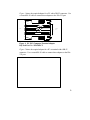
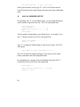
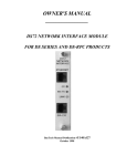
OWNER'S MANUAL
________________
V93A DAC: 14.4k bps HOST
COMMUNICATION MODEM
MODULE FOR BAYTECH
M-SERIES DAC
BayTech Manual Publication #U140E116-02
1
FCC REQUIREMENTS FOR THE V93A HOST
COMMUNICATION MODEM MODULE
1.
The Federal Communications Commission (FCC) has established
rules which permit this device to be directly connected to the
telephone network. Standardized jacks are used for these
connections. This equipment should not be used on party lines or coin
lines.
2.
If this device is malfunctioning, it may also be causing harm to the
telephone network; this device should be disconnected until the source
of the problem can be determined and until repair has been made. If
this is not done, the telephone company may temporarily disconnect
service.
3.
The telephone company may make changes in its technical operations
and procedures; if such changes affect the compatibility or use of this
device, the telephone company is required to give adequate notice of
the changes. You will be advised of your right to file a complaint with
the FCC.
4.
If the telephone company requests information on what equipment is
connected to their lines, inform them of:
a.
b.
c.
d.
The telephone number this unit is connected to
The ringer equivalence number
The USOC jack required: RJ-11
The FCC Registration Number
Items 'b' and 'd' are indicated on the label.
2
The ringer equivalence number (REN) is used to determine how many
devices can be connected to your telephone line. In most areas, the sum of
the RENs of all devices on any one line should not exceed five (5.0). If too
many devices are attached, they may not ring properly.
In the event of equipment malfunction, all repairs should be performed by our
Company or an authorized agent. It is the responsibility of users requiring
service to report the need for service to our Company or to one of our
authorized agents. Service can be obtained at:
Bay Technical Associates, Inc.
P.O. Box 387, 200 N. Second Street
Bay St. Louis, MS 39520 U.S.A.
Phone: 800-523-2702 or
228-467-8231
Fax: 228-467-4551
BBS: 228-467-4000
Home Page: www.baytechdcd.com
3
TABLE OF CONTENTS
1 GENERAL INFORMATION ...............................................................................................................6
2 SPECIFICATIONS ............................................................................................................................7
3 SOFTWARE UTILITY DISKETTE......................................................................................................8
4 CABLES & ADAPTERS ..................................................................................................................8
.1 EIA-232 CONNECTION ...............................................................................................................8
.2 MODEM CONNECTION..............................................................................................................11
5 OPERATION..................................................................................................................................11
.1 LOGIN PASSWORD .................................................................................................................11
.2 PORT SELECTION MENU..........................................................................................................12
.3 MANUAL MODE .......................................................................................................................13
.4 EXIT..........................................................................................................................................14
.5 UNIT RESET..............................................................................................................................15
.6 LOGOUT ..................................................................................................................................15
6 CONFIGURATION..........................................................................................................................16
.1 STATUS ...................................................................................................................................17
.2 SERIAL PORT CONFIGURATION..............................................................................................17
.3 PORT DEVICE NAME................................................................................................................19
.4 PORT SELECT CODE................................................................................................................20
.5 ATTENTION CHARACTER........................................................................................................20
.6 DISCONNECT TIME GUARD......................................................................................................21
4
.7 LOGIN PASSWORD .................................................................................................................21
.8 LOCAL MODEM SETUP............................................................................................................22
.9 EXIT..........................................................................................................................................23
.10 ECHO MODE...........................................................................................................................23
.11 RING DETECT RESET .............................................................................................................23
.12 MODEM LED INDICATORS......................................................................................................23
7 V93A EPROM UPGRADE..............................................................................................................24
8 V93A MECHANICAL LAYOUT......................................................................................................26
9 INDEX............................................................................................................................................27
5
1
GENERAL INFORMATION
The V93A Host Communication Modem Module is the remote user interface
to the BayTech M Series DAC (Data Acquisition and Control) units. This
module features a V.32bis/V.42bis internal modem and allows a remote host
terminal to connect and issue specific configuration or data commands to the
various I/O modules or the M Series DAC unit main board. Multiple V93A
modules can be installed in a M Series chassis allowing I/O modules to send
data to specific V93A modules. Please see the M Series DAC Owner’s
Manual for more information on the available types of I/O modules.
IMPORTANT: The first module slot of the M Series DAC base unit must
be occupied by a host module.
6
2
SPECIFICATIONS
INTERFACE: Dial-up telephone line
MODULATION: V.32bis (14,400 bps) or V.32 (9600 bps)
COMPRESSION: V.42bis, MNP5
CONNECTORS: 2 x 4-pin modular
MODULE LEDS: TD (Transmit Data), RD (Receive Data),
CD (Carrier Detect), MR (Modem Ready), and CX
(Connection) status LEDs.
TRANSMIT LEVEL: -10 dBm (dial-up)
RECEIVER SENSITIVITY: -45 dBm
DIMENSIONS: 6"h x 4.5"w.
FACTORY POWER-UP DEFAULT CONFIGURATIONS:
Port Select Code: $BT
Password: BTA, disabled
USER-PROGRAMMABLE CONFIGURATIONS:
Easy to configure using on-screen menu. Choices are
saved in non-volatile memory to become the new
power-up default configuration.
7
3
SOFTWARE UTILITY DISKETTE
IMPORTANT: Copy the BayTech original diskette onto a blank
diskette and store the original in a safe place.
BayTech provides utility software for DOS compatible PCs to assist you in
configuring your M-Series DAC unit. This diskette contains several
programs, however the only programs that will be used is TERM.EXE and
README.RDM. TERM.EXE is a terminal emulation program for DOS
compatible PCs used to configure the various features of the unit.
Please review the README.RDM file to obtain instructions for TERM.EXE.
To view the README.RDM file on your screen, first insert
the diskette into your PC's disk drive and then enter the
command TYPE README.RDM from your disk drive
prompt. To print this file, enter the command COPY
README.RDM LPT1: from your disk drive prompt
4
CABLES & ADAPTERS
The V93A modem has two modular connectors for device selection and
configuration. One connector is for connection to a dial-up line. The other
connector is used to communicate with an EIA-232 port.
.1
EIA-232 CONNECTION
Connect the eight pin modular cable(RJ-45) to the port labeled EIA-232 on
the V93A. Connect the DB9 adapter to the serial port of your PC or terminal
and then connect the other end of the cable to the RJ-45 side of the adapter.
Use adapter BayTech part number 9FRJ45PC-3 and cable, BayTech part
number RJ08X007 that come with the RPC.
8
Figure 1 shows the required adapter for a PC with a DB-25 connector. Use
a crossed RJ-45 cable to connect these adapters to the EIA-232 port.
1
BLUE
2
ORANGE
3
BLACK
1
RJ-45
4
RED
5
GREEN
6
YELLOW
7
BROWN
8
GRAY
DCD
2
RX
3
TX
4
DTR
5
GND
6
DSR
7
RTS
8
CTS
FEMALE
DE-9
Figure 1: PC, PS/2 Computer/Terminal Adapter
BayTech Part No. 9FRJ45PC-3
Figure 2 shows the required adapter for a PC or terminal with a DB-25
connector. Use a crossed RJ-45 cable to connect these adapters to the EIA232 port.
9
RJ-45
1
BLUE
2
ORANGE
3
BLACK
4
RED
5
GREEN
6
YELLOW
7
BROWN
8
GRAY
2
TX
3
RX
4
RTS
5
6
DSR
7
GND
8
DCD
20
DTR
CTS
FEMALE DB-25
Figure 2: PC, PS/2 Computer/Terminal Adapter
BayTech Part No. 25FRJ45PC-3
IMPORTANT: When modular connectors are used as shown in Figures 1 2 above with RJ-45 connectors, crossed RJ-45 cables are required. See the
cable diagram that follows.
RJ-45
RJ-45
PIN
PIN
1
1
2
2
3
3
4
4
5
5
6
6
7
7
8
8
Figure 3:
RJ-45 Cable
BayTech Part No. RJ08X010 (10 feet)
10
COLOR
BLUE
ORANGE
BLACK
RED
GREEN
YELLOW
BROWN
GRAY
.2
MODEM CONNECTION
Connect the phone line to the RJ-11 connector on the V93A with a RJ-11
cable.
5
OPERATION
a. You are ready to perform commands when a terminal or PC is
communicating with:
(1) the V93A's EIA-232 port.
(2) a remote modem is communicating with the V93A’s
modem.
b. If you are using a PC, you can communicate with the V93A by
using a terminal emulation program or by using a software communications
program that emulates a terminal. BayTech supplies an utility diskette which
includes TERM.EXE, a terminal emulation program, to put your PC into
terminal emulation mode. Popular communication software packages such as
PROCOMM PLUS(R) by Data Storm Technologies, also provide terminal
emulation capabilities and allow for communications with the V93A.
c. If configuring the V93A from the EIA-232 port, configure the host
terminal’s serial parameters to match those of the V93A. From the factory,
the V93A is set at 9600 baud, 8 data bits, 1 stop bit no parity and
XON/XOFF disabled.
.1
LOGIN PASSWORD
Once the V93A has been connected to the phone line and configured for the
desired parameters, a remote host computer can make a connection to the
V93A modem over a dial line and perform data acquisition and control
functions with the various M Series I/O modules. The V93A will send a
message similar the following when a remote host computer establishes a
connection:
M-Series V93A DAC Host
11
Unit 2 Module 1
REV. 4.XX Copyright (c)
Bay Technical Associates
1995-1997
To login, enter password
Login: BTA (default)
You will be prompted to type in the desired password followed by
<ENTER> when a connection to the V93A modem is first made. You are
given three tries to type in the correct password before the modem hangs up.
Type the appropriate password (Default is BTA). The V93A will respond
with:
Login successful
Port Select Code: $BT
Attnetion Character: ;
Among the functions you can perform are data commands/port selection and
configuration. Configuration commands are used to program the features of
the various I/O modules and the data commands are typically used to request
stored data received from an I/O module. Data commands are also used to
instruct certain I/O modules to perform a specific task (e.g., energize or deenergize a relay).
The configuration menu is invoked by selecting configure(C) from the port
selection menu. The supported configuration and data commands for a
specific I/O module are described in the documentation for that module.
.2
PORT SELECTION MENU
To activate the port selection menu, type 5 or more ;;;;; (default) in a row
and a menu similar to the following will appear.
.
M-Series V93A DAC Host
Unit 1 Module 2
REV. 4.00 Copyright(c) 1995-1997
Bay Technical Associates
Device A
12
(2,1)............1
Device B
(2,2)............2
Device C
(2,3)............3
Device D
(2,4)............4
Configure.........................C
Manual Mode.......................M
Exit..............................X
Unit Reset........................R
Logout............................T
Enter Request :
The device names in the menu correspond to the device names assigned to
the serial ports installed in the unit. To select a particular device simply enter
the number of the device then hit return. Refer to section 16.4 of the MSeries DAC owners manual for configuration of device names.
The other items in the menu provide various functions described below:
Configure - Allows users enter into the configuration mode for any
installed modules or for the base unit. See Section 6 CONFIGURATION for
details to configure the unit.
.3
MANUAL MODE
Manual Mode allows users to manually select a module and/or port. The
“Manual Mode” selection for the V93A menu is used to make a module level
connection which is used for sending commands to the module. The “Manual
Mode” is used to make a connection to a module such as the Control Relay
Module, A-to-D Module, Event Counter Module, main board, etc. Use the
“Manual Mode” for module connections other than a Serial I/O module
unless you want to operate a Serial I/O module in the Command Mode of
operation. The “Manual Mode” selection should not be used for
configuration.
13
By responding to the Enter Request: message at the end of the V93A menu
with “M” you receive a response similar to the following:
Device A
(2,1).................... 1
Device B
(2,2).................... 2
Device C
(2,3).................... 3
Device D
(2,4).................... 4
Device A
(3,1).................... 5
Device B
(3,2).................... 6
Device C
(3,3).................... 7
Device D
(3,4).................... 8
Configure ............................... C
Manual Mode ............................. M
Exit......................................X
Unit Reset .............................. R
Logout .................................. T
Enter Request:
M
Enter Module number: 2
Enter Port number (<CR> for none): 3
By entering “2” at the Enter Module number and entering “3” at the Enter
Port number, the user has selected module number 2 and port number 3.
Verify the connection by insuring that the red LED of Port 3, Module 2 on the
front panel of the M-Series DAC base unit has been selected.
.4
EXIT
By responding to the Enter Request: message in the V93A Status &
Diagnostics Menu with “X” (Exit), you will exit the V93A Status &
Diagnostics Menu. The V93A host module will respond with a menu that is
similar to the following:
.1
>X
14
.5
UNIT RESET
Users can instruct the M-Series DAC with the V93A module, to “reset” by
using the Menu Selection Method to reset the unit. The Unit Reset command
does not affect any saved configuration parameters that have been changed
from the default values.
By responding to the Enter Request: message at the end of the menu with
“R”(Unit Reset), you will reset the M-Series unit.
Device A
(2,1).................... 1
Device B
(2,2).................... 2
Device C
(2,3).................... 3
Device D
(2,4).................... 4
Device A
(3,1).................... 5
Device B
(3,2).................... 6
Device C
(3,3).................... 7
Device D
(3,4).................... 8
Configure ............................... C
Manual Mode ............................. M
Exit......................................X
Unit Reset .............................. R
Logout .................................. T
Enter Request:
R
The M-Series DAC unit has been reset.
Important: The Unit Reset command will terminate communications with
connected equipment to the M-Series DAC.
You must re-establish communications with the M-Series DAC system after
the unit has been reset.
The Menu is invoked by sending the Attention Character(default ;;;;;) to
the V93A host module five times. The V93A will respond with a menu similar
to the following, if two Serial I/O modules are installed.
.6
LOGOUT
15
By responding to the Enter Request: message in the V93A Main Menu with
“T” (Logout), you will take you out of menu mode If you have a modem
connection it will terminate that connection. The V93A host module will
respond with a message similar to the following:
Device
Device
Device
Device
Device
Device
Device
Device
A
B
C
D
A
B
C
D
(2,1)....................
(2,2)....................
(2,3)....................
(2,4)....................
(3,1)....................
(3,2)....................
(3,3)....................
(3,4)....................
1
2
3
4
5
6
7
8
Configure ............................... C
Manual Mode...... ....................... M
Exit......................................X
Unit Reset .............................. R
Logout .................................. T
Enter Request:
To return to the menu after making a connection, simply type 5 or more ‘;’
semicolons(default).
NOTE: Menu selection is case sensitive.
6
CONFIGURATION
To access configuration, bring up the menu and select option ‘C’. Select the
module number associated with the V93A. For example, if the V93A is
installed in module slot 4, select the number from the menu that is associated
with Module 4. The menu below will appear.
Status.............................1
Serial Port Configuration..........2
Port Device Name...................3
Port Select Code...................4
Attention Character................5
Disconnect Timeguard...............6
Login Password.....................7
Local Modem Setup..................8
Exit...............................X
16
Enter Request :
.1
STATUS
By responding to the menu with a "1" (Status), you can review the current
configuration of the V93A. Below is the default status.
Installed Modules :1,2
Port Select Code is................$BT
Attention Character is.............;
Disconnect Time Guard is...........Disabled
Local Modem Setup :
Rings to Auto-Answer................2
Modem Connectivity Time-out is......Disabled
Login Setup:
Login Password is...................BTA
Strike any Key to Continue
+----+-----------+-----+-----+----+------+-----+---+
|Port|
Device |Baud |Word |Stop|Parity|Xon/Xoff|
|
|
Name
|Rate |Size |Bits|
|Xmit|Recv|
+----+-----------+-----+-----+----+------+-----+---+
| 1 |HostEIA-232|9600 | 8 | 1 | None |Off |Off|
| 2 |Host MODEM |57.6k| 8 | 1 | None |Off |Off|
+----+-----------+-----+-----+----+------+-----+---+
Strike any Key to Continue
.2
SERIAL PORT CONFIGURATION
By responding with "2" (Serial Port Configuration), you can change serial
configuration for the EIA-232 port on the V93A. The V93A will then
respond with:
Enter Host Device Number (1-2): 1
Module 1 Serial Port Configuration :
+----+-----------+-----+-----+----+------+-----+---+
|Port|
Device |Baud |Word |Stop|Parity|Xon/Xoff |
|
|
Name
|Rate |Size |Bits|
|Xmit|Recv|
+----+-----------+-----+-----+----+------+-----+---+
| 1 |Device A
|9600 | 8 | 1 | None |Off |Off |
+----+-----------+-----+-----+----+------+-----+---+
17
Exit/Save......1
Set Baud Rate..2
Set Word Size..3
Set Stop Bits.....4
Set Parity........5
Set Xon/Xoff......6
Enter Request :
You can now reconfigure the V93A EIA-232 port by sending the appropriate
option (1 to 6) from the menu. For example, to change the baud rate to
115.2K, send "2" (Set Baud Rate). The V93A will respond with:
1
2
3
4
5
6
7
8
9
A
B
Enter
For
300
For
600
For 1200
For 2400
For 4800
For 9600
For 19200
For 38400
For 57.6K
For 76.8K
For 115.2K
Request :
Send "B" for 115.2K baud rate. The V93A will respond with the
reconfigured status of the port as follows:
Module 2 Serial Port Configuration :
+----+-----------+-----+-----+----+------+-----+---+
|Port|
Device |Baud |Word |Stop|Parity|Xon/Xoff|
|
|
Name
|Rate |Size |Bits|
|Xmit|Recv|
+----+-----------+-----+-----+----+------+-----+---+
| 1 |Device A
|115.2| 8 | 1 | None |Off |Off|
+----+-----------+-----+-----+----+------+-----+---+
Exit/Save......1
Set Stop Bits.....4
Set Baud Rate..2
Set Parity........5
Set Word Size..3
Set Xon/Xoff......6
Enter Request :
You can now select other options from the menu.
If there are no other changes, send "1" (Exit/Save) and the V93A will respond
with:
Save Changes Permanently ? (Y/N) :
18
If you type "Y", the new configuration for the selected port is stored
permanently in non-volatile memory until. If you type “N” the V93A will
return to the main configuration menu.
NOTE: If you are configuring the V93A from the EIA-232 port, the V93A
will respond with:
Change Device to NEW Configuration
Before Answering This Request.
CAUTION: This message reminds you to change the serial port
configuration of the host device now. If they do not match, the V93A will be
unable to interpret the next command. If this happens, cycle power on the MSeries DAC and reconfigure the unit.
.3
PORT DEVICE NAME
By responding with "3" (Port Device Name), you can change the Port Device
Name. The V93A module will respond with a menu similar to the following:
Module 1 Device Name :
+----+-----------+-----+-----+----+------+-----+---+
|Port|
Device |Baud |Word |Stop|Parity|Xon/Xoff|
|
|
Name
|Rate |Size |Bits|
|Xmit|Recv|
+----+-----------+-----+-----+----+------+-----+---+
| 1 |Device D
|9600 | 8 | 1 | None |Off |Off|
+----+-----------+-----+-----+----+------+-----+---+
Enter Port Device Name (Max. 16 characters):
or ENTER for no change ...........:
Enter the desired Port Device Name up to 16 characters. For example, if you
type "PORT 4" followed by <ENTER>, the module will respond with:
Module 1 Device Name :
+----+-----------+-----+-----+----+------+-----+---+
|Port|
Device |Baud |Word |Stop|Parity|Xon/Xoff|
|
|
Name
|Rate |Size |Bits|
|Xmit|Recv|
+----+-----------+-----+-----+----+------+-----+---+
| 1 |Port 4
|9600 | 8 | 1 | None |Off |Off|
+----+-----------+-----+-----+----+------+-----+---+
19
Enter Port Device Name (Max. 16 characters):
or ENTER for no change ...........:
If the Port Device Name is satisfactory, type <ENTER>. The V93A will
return to the main configuration menu.
NOTE: If the V93A Connect Port ID Echo feature is programmed for Use
Device Name, the message sent to the host device when the host selects a
V74/V75 peripheral port will be the Device Name shown in the menu above.
.4
PORT SELECT CODE
By responding with "4" (Port Select Code), you can change the Port Select
Code to any ASCII character string from 1 to 8 characters. The V93A will
respond with:
Port Select Code is................$BT
Enter Port Select Code (Max. 8 characters):
or ENTER for no change..............:
Type the desired Port Select Code followed by <ENTER>. For example, if
you type #PORT followed by <ENTER>, the V93A will respond with:
Port Select Code is................#PORT
Enter Port Select Code (Max. 8 characters):
or ENTER for no change..............:
If no additional change is desired, type "ENTER". The V93A will store the
new Port Select Code permanently into non-volatile memory and return to the
main configuration menu.
.5
ATTENTION CHARACTER
By responding with "5" (Attention Character), you can change the Attention
Character to be any ASCII character. The V93A will respond with:
Attention Character is............ ;
Change It ? (Y/N) :
20
Type "Y" to change the Attention Character. The V93A will respond with:
Enter Attention Character :
Type the desired Attention Character. For example, if you type "%", the
V93A will respond with
Attention Character is............ %
Change It ? (Y/N) :
Type "N" if no additional change is desired. The V93A will store the new
Attention Character into non-volatile memory and return to the main
configuration menu.
.6
DISCONNECT TIME GUARD
By responding with "6" (Disconnect Time Guard), you can determine if you
want a one second delay. The V93A will respond with:
Disconnect Time Guard is..................Enabled
Change It? (Y/N):N
Type "Y", to toggle the existing state of Disconnect Time Guard or "N" for no
change. The V93A will store the selected state of the Disconnect Time Guard
into non-volatile memory and return to the main configuration menu.
.7
LOGIN PASSWORD
By responding with "7" (Login Setup), you can change the Login Password.
The V93A will respond with:
Login Password Is....................BTA
Change It: (Y/N):
Type “Y” to enter the new password up to 8 ASCII characters followed by
<ENTER>. For example, if you what to change the Login Password to
LOGIN, type "LOGIN" at the prompt. The V93A will respond with:
21
Enter New Password( 1 - 8 char., CR to end):
If the Login Password is correct, type "N". The V93A will store the new
Login Password into non-volatile memory and return to the main configuration
menu.
.8
LOCAL MODEM SETUP
By responding with “8” (Local Modem Setup), you can change the Rings to
Answer and the Connectivity Time-out. The V93A will respond with:
Local Modem Setup:
Rings to Answer......................1
Connectivity Time-out................2
Exit.................................X
Enter Request :
Type the number corresponding to your desired choice. For example, if you
type “1” (Rings to Answer), the V93A will respond with:
Rings to Auto-Answer...............1
Change It ? (Y/N) :
Type “Y” to change the Number Rings to Auto-Answer setting. The V93A
will respond:
Enter Number of Rings to Auto-Answer (1 to 4)
:
The V93A will store the Number of Rings to Auto-Answer in non-volatile
memory and return to the main configuration menu.
By responding to the message in the Local Modem Setup menu with "2"
Connectivity Time-out: The V93A will respond with:
Enter Request : 2
Modem Connectivity Time-out is.....5 minutes
Change It ? (Y/N) :
22
This time-out can be programmed from 5 to 255 minutes, or 0 (=disable). The
timer is started when the modem goes off-hook (DCD goes high), and the
modem will return to “on hook” after the time-out has expired. The factory
default is 0 (disabled).
.9
EXIT
By responding with "X" (Exit), you will exit configuration mode. At this point,
the V93A is awaiting a command from the host device
(i.e., Attention Character sent five times).
.10
ECHO MODE
The V93A can be placed into echo mode by sending seven semicolons (;) in
succession. While in echo mode, the V93A will echo all characters received
by the connected device back to that device. Echo mode is terminated by
placing an I/O module into command mode ($BTm<cr> where m is the
desired module number. Echo Mode would be used only when the ASCII
string method of port selection is used. If the Menu Mode(Attention character
method) of port selection is used the Echo Mode is not required.
.11
RING DETECT RESET
The V93A has a Ring Detect Reset feature that will automatically cycle power
on the M Series unit if an incoming call is detected and not answered within
seventy seconds. The Ring Detect Reset feature is enabled by connecting a
straight 2-wire or 4-wire cable between the auxiliary 4-pin modular connector
on the V93A and the DIAL service modem port on the M Series chassis.
.12
MODEM LED INDICATORS
23
The V93A has five LEDs on the rear panel that indicate the modem status:
TD, RD, CD, MR, and CX. These LEDs are described below.
LED
Description
TD
Transmit Data: Indicates the modem is transmitting data.
RD
Receive Data: Indicates the modem is receiving data.
CD
Carrier Detect: Indicates a valid carrier tone has been detected.
MR
Modem Ready: Indicates the modem is ready to communicate.
CX
Connection: Indicates the V93A has a connection to the main board, to a module, or to
an individual channel or port.
7
V93A EPROM UPGRADE
You will receive one EPROM (chip with label) for each module to be
upgraded.
The materials you will need to supply are:
Flat blade screwdriver
IC DIP extractor or a pair of curved needle-nose pliers
1.
IMPORTANT: Remove power from the unit by depressing the
power switch on the front of the unit to OFF. Also remove power
cord from the AC outlet.
2.
Remove the appropriate module by loosening the 2 straight slot
screws that attach the connector board I/O module to the chassis and
then pulling the module out.
3.
Refer to Appendix B (V93A Mechanical Layout) and locate socket
U2. Remove existing EPROM from socket U2 with IC extractor or
needle-nose pliers. Gradually loosen each side of the chip, alternating
24
pliers from side to side, so as not to bend chip pins. Pull loosened
EPROM all the way out.
4.
Install the new EPROM into socket U2. The EPROM is notched; the
notch on the EPROM should line up with the notch on the socket. Be
careful not to bend any of the pins. Make sure none of the pins miss
their sockets. If the socket has more holes than chip pins, the pins
should line up starting at the edge of the board.
5.
Re-install the V93A and apply power to the unit. The upgrade is now
complete. Before you begin operations, check the configuration status
to make certain it matches your application. See Section 5 for
complete instructions.
25
8
V93A MECHANICAL LAYOUT
È
C5
R6
>
L1
F1
K
M1
K
>
L2
R7
F2
J2
C6
PN:M330A048A
SN:
LED1
LED2
C15
C8
R9
LED3
F
F
F
F
U9
F
F
F
LED4
F
F
F
F
F
F
U2
C16
F
F
C19
LED5
F
F
F
F
F
F
C9
F
F
U11
F
U10
F
F
F
F
F
U8
F
F
F
F
F
F
F
F
F
F
F
F
F
F
F
F
F
È
Error!
Switch argument not specified.
26
9
INDEX
—A—
ASCII character, 19
Attention Character, 19
Auto-Answer, 20
—C—
Case sensitive, 15
Communications program, 10
Configuration menu, 17
—D—
DCD Logon/Logoff, 21
Disconnect Time Guard , 19
—E—
Emulation, 11
Exit, 14, 21
—N—
Non-volatile memory , 17, 19
—O—
Off-hook, 21
—P—
Port Device Name , 18
Port Select Code, 18
Port Selection, 14
PROCOMM PLUS(R), 11
—R—
README.RDM , 8
Reconfigured status, 17
Reset, 14
—S—
—H—
Header, 20
Serial Port Configuration, 16
Set Baud Rate, 16
Status, 16
—I—
—T—
ID Echo, 18
—L—
Local Modem Setup, 20
Login Password , 20
Login Setup, 20
Logout, 15, 21
TERM.EXE, 8, 11
Terminal emulation, 10
Time-out, 21
—U—
Unit Reset, 14
Utility software , 8
—M—
Menu selection, 15
Modular connectors , 10
27