1
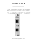
OWNER'S MANUAL
________________
DS73 & DS73TP ETHERNET
PERIPHERAL COMMUNICATIONS
MODULE FOR THE
DS-DATA SWITCH
BayTech Manual Publication #U140A126
Thank you for selecting a DS73 or DS73TP Ethernet Peripheral Communications Module for the DS
Data Switch.
The data provided in this Owner's Manual explains the various ways you can operate your
DS73/DS73TP Peripheral Communications Module and configure it to your own computer system.
We suggest that you read this manual carefully before attempting to install the module and that you place
special emphasis on correct cabling and configuration. If you have any problems with your installation,
please contact a BayTech applications engineer for assistance at 800-523-2702.
BayTech manufactures many data acquisition and control products, statistical multiplexers, printer
sharing solutions, remote power switches and network print servers. If you would like information on
any of these products, please contact BayTech customer service.
We welcome any comments you may have about our products. And we hope that you will continue to
look to BayTech for your data communications needs.
2
NOTE: The information contained in this document is subject to change without notice.
Copyright 1997 by Bay Technical Associates, Inc.
BayTech, Telplex, LaserShare, Print Master and TRAN-X are registered trademarks of Bay
Technical Associates, Inc.
IBM, IBM PC, IBM PC/AT, IBM PC/XT are products and registered trademarks of International
Business Machines Corporation.
Hewlett-Packard LaserJet is a product and registered trademark of the Hewlett-Packard
Company.
All products or company names are trademarks of their respective holders.
3
TABLE OF CONTENTS
TABLE OF CONTENTS ...................................................................................................................................................................4
1 GENERAL INFORMATION ........................................................................................................................................................6
2 SPECIFICATIONS.........................................................................................................................................................................6
3 CABLING........................................................................................................................................................................................7
3.1 10BASE2 (COAX) CONNECTION...........................................................................................................................................7
3.2 10BASE-T (MODULAR) CONNECTION ...............................................................................................................................7
4 OPERATION..................................................................................................................................................................................7
4.1 PROGRAMMABLE FEATURES .............................................................................................................................................7
4.1.1 IP ADDRESS.......................................................................................................................................................................7
4.1.2 SUBNET MASK.................................................................................................................................................................7
4.1.3 GATEWAY.........................................................................................................................................................................8
4.1.4 SELECT CODE....................................................................................................................................................................8
4.1.5 PASSWORD.......................................................................................................................................................................8
4.1.6 USER INTERFACE ........................................................................................................Error! Bookmark not defined.
4.2 DS73 PERIPHERAL CONNECTION....................................................................................Error! Bookmark not defined.
4.3 REVERSE TELNET OPERATION ........................................................................................Error! Bookmark not defined.
4.4 RESOURCE RELEASE FUNCTION.....................................................................................Error! Bookmark not defined.
5 USER INTERFACE....................................................................................................................Error! Bookmark not defined.
5.1 MENU MODE/ATTENTION CHARACTER METHOD ..................................................Error! Bookmark not defined.
5.1.1 IMMEDIATE DATA COLLECTION ..........................................................................Error! Bookmark not defined.
5.1.2 CONFIGURATION ............................................................................................................................................................8
5.1.2.1 MODULE CONFIGURATION ..................................................................................................................................8
5.1.2.2 MAIN BOARD CONFIGURATION.....................................................................Error! Bookmark not defined.
5.1.3 MANUAL CONNECTION............................................................................................Error! Bookmark not defined.
5.1.4 UNIT RESET .....................................................................................................................................................................11
5.1.5 MODULE STATUS .......................................................................................................Error! Bookmark not defined.
5.1.5.1 SYSTEM STATUS .................................................................................................Error! Bookmark not defined.
5.1.5.2 INTERNAL COMMUNICATIONS......................................................................Error! Bookmark not defined.
5.1.5.3 NETWORK INTERFACE ......................................................................................Error! Bookmark not defined.
5.1.5.4 LOGGED USERS .....................................................................................................Error! Bookmark not defined.
5.1.5.5 EXIT............................................................................................................................................................................11
5.1.6 LOGOUT............................................................................................................................................................................12
5.2 ASCII STRING COMMAND METHOD.............................................................................Error! Bookmark not defined.
6 MESSAGES ................................................................................................................................Error! Bookmark not defined.
7 MODULE DIAGNOSTICS .......................................................................................................Error! Bookmark not defined.
7.1
7.2
7.3
7.4
4
LED INDICATORS.................................................................................................................Error! Bookmark not defined.
DIAGNOSTIC LED INDICATIONS.....................................................................................Error! Bookmark not defined.
OPERATIONAL MODE........................................................................................................Error! Bookmark not defined.
INTERACTIVE DIAGNOSTICS...........................................................................................Error! Bookmark not defined.
8 DS73 & DS73TP CONFIGURATION......................................................................................Error! Bookmark not defined.
8.1 MAIN CONFIGURATION MENU.......................................................................................Error! Bookmark not defined.
8.2 IP ADDRESS...............................................................................................................................................................................9
8.3 SUBNET MASK.......................................................................................................................................................................10
8.4 GATEWAY...............................................................................................................................................................................10
8.5 SELECT CODE........................................................................................................................Error! Bookmark not defined.
8.6 PASSWORD .............................................................................................................................................................................10
8.7 DS73/DS73TP USER INTERFACE.......................................................................................Error! Bookmark not defined.
8.7.1 ID MSG: MODULE ID MESSAGE..............................................................................Error! Bookmark not defined.
8.7.2 LOGIN: LOGIN PROCEDURE.......................................................................................Error! Bookmark not defined.
8.7.3 IMR: IMMEDIATE MODE MESSAGE QUICK RELEASE.....................................Error! Bookmark not defined.
8.7.4 CRT: CARRIAGE RETURN TRANSLATION-STRIP LINE FEEDS OR NULLSError! Bookmark not defined.
8.7.5 MENU: MENU MODE OF OPERATION ..................................................................Error! Bookmark not defined.
8.7.6 ATTN: MENU ATTENTION CHARACTER............................................................Error! Bookmark not defined.
8.7.7 PROGRAMMABLE BREAK........................................................................................Error! Bookmark not defined.
8.7.8 PERIPHERAL CONFIGURATION...............................................................................Error! Bookmark not defined.
8.7.9 REVERSE TELNET OPERATION................................................................................Error! Bookmark not defined.
9 GETTING STARTED ..................................................................................................................................................................13
10 MAINTENANCE.......................................................................................................................................................................13
11 RETURNS TO THE FACTORY...............................................................................................................................................14
12 REPACKAGING FOR SHIPPING............................................................................................................................................14
13 TECHNICAL SUPPORT ...........................................................................................................................................................14
14 FEDERAL COMMUNICATIONS COMMISSION RADIO FREQUENCY INTERFACE STATEMENT......................14
15 DS73/DS73TP EPROM UPGRADE.........................................................................................................................................15
16 DS73/DS73TP MECHANICAL LAYOUT..............................................................................................................................16
INDEX ...............................................................................................................................................................................................17
5
1
GENERAL INFORMATION
The DS73 and the DS73TP peripheral communications module supports remote access to TCP/IP Ethernet networks
by using the DS-Series Data Switch with a modem module installed. Remote users can dial into the DS-Series unit
and connect to network hosts from anywhere at anytime. Both remote in-band and out-of-band management is
available by using one DS-Series data switch. Use the DS73 module for in-band network management. And use the
DS74, EIA-232 module for out-of-band management.
Remote workstations and PCs connect to the DS73 using a dial-up PPP session. This offers dial-up users a low cost
IP network link suitable for remote access to the network.
IMPORTANT: You should determine what types of peripheral modules you have installed in your DS-Series unit in
addition to the DS73 peripheral module. You should familiarize yourself with the various operation modes of the
installed peripheral modules. A brief operational description of each peripheral module is provided in the DS-Series
Owner’s Manual.
2
SPECIFICATIONS
PROTOCOLS: PPP, TCP/IP, ARP & ICMP
NETWORK INTERFACE: Ethernet; IEEE 802.3 compliant, 10BASE2 (thin coax,
BNC) and 10BASE-T (twisted pair, RJ-45). Automatic media and frame selection. The DS73 has
both 10BASE-T and 10BASE2 connectors. The DS73TP has a 10BASE-T connector.
FRAME TYPES: Ethernet II & SNAP(802.3)
SPEEDS: 10 mbps
BUFFER SIZE: 256 KB
SECURITY: Password protected log-on procedure
INDICATORS: Green LED - Link integrity
Red LED - RX/TX
Red LED - Connection status(CX)
POWER REQUIREMENTS: Supplied by DS-Series base unit.
+5 VDC, 300 mA
ENVIRONMENT: Operating Temperature Range: 0° to 70° C.
Storage Temperature Range: -40° to 80° C.
Humidity: 5 to 95% RH.
6
3
CABLING
CAUTION: Power should be turned off when cables are being installed.
3.1
10BASE2 (COAX) CONNECTION
The 10BASE2 port of the DS73 peripheral module connects to any BNC connector on the network cable. BayTech
provides a T-connector for this purpose. The DS73TP has a 10BASE-T connector only. Please see the figure below.
3.2
10BASE-T (MODULAR) CONNECTION
If your network uses 10BASE-T, RJ-45 connectors, connect an RJ-45 cable between the RJ-45 port and the network
hub. The modular port is defined as DTE (i.e., Pin 1 is TD+, Pin 2 is TD-, Pin 3 is RD+, and Pin 6 is RD-). Most RJ-45
network hubs will require a straight cable type. The LINK (link integrity) LED on the back panel and at the connected
port on the hub will illuminate if there is a good connection between the DS73/DS73TP and the hub.
4
OPERATION
4.1
PROGRAMMABLE FEATURES
4.1.1
IP ADDRESS
The IP Address is the network address for the DS73 peripheral module. The IP Address consists of four bytes with
each byte ranging from 0 to 255 decimal. This parameter must be programmed before the DS73 can be accessed on
the network. The factory default IP Address is 0.0.0.0.
4.1.2
DIAL-IN IP ADDRESS
The Dial-up IP Address is the address given to the dial-in user during the establishment of the PPP link. The Dial-in
IP Address consists of four bytes with each byte ranging from 0 to 255 decimal. This parameter must be programmed
before the DS73 can be accessed on the network. The factory default IP Address is 0.0.0.0.
4.1.3
SUBNET MASK
The SUBNET Mask is a bit mask that identifies the network portion of the IP address, allowing the DS73 to determine
whether to send a packet directly to the client or to a gateway. The Subnet Mask consists of four bytes with each
byte ranging from 0 to 255 decimal. This parameter must be programmed before the DS73 can be accessed on the
network. The factory default Subnet Mask is 0.0.0.0.
7
4.1.4
GATEWAY
The Gateway is the address of a router for connection to other networks. The Gateway address consists of four
bytes with each byte ranging from 0 to 255 decimal. The factory default Gateway address is 0.0.0.0.
4.1.5
PRIMARY DNS
The Primary DNS (domain name server) IP address to be provide if the user will be accessing domain name server on
the network.
4.1.6
SECONDARY DNS
The Secondary DNS (domain name server) IP address to be provide if the user will be accessing domain name server
on the network.
4.1.7
PRIMARY NBNS
The Primary NBNS (Net BIOS Name Server) IP address to be provide if the user will be accessing domain name server
on the network.
4.1.8
SECONDARY NBNS
The Secondary NBNS (Net BIOS Name Server) IP address to be provide if the user will be accessing domain name
server on the network.
4.1.9
USER NAME
The DS73 User name is required of all users who attempt to access the DS73. The user name is given by the user
when establishing a connection to the DS 73 module. The user name consists of an ASCII character string with a
maximum length of 8 characters. The factory default user name is “user1”.
4.1.10
PASSWORD
The DS73 Password is required of the user prior to being granted access to the network. The user, when
establishing a connection to the DS73. The Password consists of an ASCII character string with a maximum length of
8 characters. The factory default Password is BTA.
4.1.11
MODULE NAME
The DS73 Module name is name reported by the module upon connection. The module name consists of an ASCII
character string with a maximum length of 8 characters. The factory default module name is “DS73”.
4.1.12
EXIT
To exit the DS73 configuration menu strike “X” (Exit).
5
DS73 MODULE CONFIGURATION
Configuration changes to the DS-Series with a DS73 Ethernet module installed are made through the DS71 Host
module or through the EIA-232 service port. The DS73 will respond with a menu prompting you to enter the desired
module number. By responding to “C” to change the configuration of a DS data switch with a DS73 installed in
Module 2 and two other modules, you will see a menu similar to the following:
Data Switch Series -F.1.07
8
Bay Technical Associates
Port Select Code: $BT
Attention Character: ;
DS73
(2,1).................... 1
Device A
(3,1).................... 2
Device B
(3,2).................... 3
Device C
(3,3).................... 4
Device D
(3,4).................... 5
Configure ............................... C
I/O Module Reset ........................ RM
Unit Reset .............................. RU
Exit .................................... X
Logout .................................. T
Enter Request : C
Configuration
Module 1...............1
Module 2...............2
Module 3...............3
Select Port............S
Exit...................X
Enter Request: 2
By responding to the Enter Request: message at the end of the configuration menu with “2” you receive the
configuration menu for Module 2 that looks similar to the following:
DS73 Ethernet Module
F 0.02 Copyright (c) 1997
Bay Technical Associates
Enter user name:
user1
Enter password: BTA
Login successful.
Module IP Address:
200.4.3.72
Subnet Mask:
255.255.255.0
Primary DNS:
0.0.0.0.
Primary NBNS:
0.0.0.0.
Ethernet Addr: 00.C0.48.1A.24.5D
IP Address.................... 1
Dial-In IP Address:
200.4.3.73
Gateway Addr: 200.4.3.1
Secondary DNS:
0.0.0.0.
Secondary NBNS:
0.0.0.0.
ID MSG/Login: enabled/enabled
Network Cable Connections: good
Module IP Address............. 1
Dial-In Ip Address............ 2
Subnet Mask................... 3
Gateway....................... 4
Primary DNS................... 5
Secondary DNS................. 6
Primary NBNS.................. 7
Secondary NBNS................ 8
User Name..................... 9
Password..................... 10
Module name...................11
Exit.......................... X
NOTE: For detailed configuration information see the DS-Series Owner’s Manual Number U140E121-03(Section 6).
IMPORTANT: There should be no active connections while configuring the unit. Reset the base unit after
configuration.
5.1
MODULE IP ADDRESS
9
Type “1” (Module IP Address), at the end of the main configuration menu and you can program the IP address. The
DS73 will respond with:
Enter Module IP address in dotted decimal form:
Enter the desired Module IP address as a series of four numbers separated by periods (e.g., 197.3.14.9) followed by
Carriage Return.
NOTE: The first part of the Module IP address is determined by assigned network address.
IMPORTANT: The Module IP address must be programmed before the DS73 module can be accessed on the
network. After programming the IP address, the unit must be reset for the new information to take effect.
5.2
DIAL-IN IP ADDRESS
Type “2” (Dial-in IP Address) at the end of the main configuration menu and you can program the Dial-in IP
address. The DS73 will respond with:
Enter Dial-in IP address in dotted decimal form:
Enter the desired Dial-in IP address as a series of four numbers separated by periods (e.g., 197.3.14.9) followed by
Carriage Return.
NOTE: The first part of the Module IP address is determined by assigned network address.
IMPORTANT: The Module IP address must be programmed before the DS73 module can be accessed on the
network. After programming the IP address, the unit must be reset for the new information to take effect.
8.3
SUBNET MASK
Type “3”(Subnet Mask) at the end of the main configuration menu and you can program the Subnet Mask. The
DS73 will respond with:
Enter Subnet Mask in dotted decimal form:
Enter the desired Subnet Mask as a series of four numbers separated by periods (e.g., 255.255.255.0) followed by
Carriage Return.
IMPORTANT: The Subnet Mask must be programmed before the DS73 module can be accessed on the network.
After programming the Subnet Mask, the unit must be reset for the new information to take effect.
8.4
GATEWAY
Type “4”(Gateway) at the end of the main configuration menu and you can program the Gateway or router address.
The DS73 will respond with:
Enter Gateway address in dotted decimal form:
Enter the desired Gateway or router address as a series of four numbers separated by periods (e.g., 197.3.14.1)
followed by Carriage Return.
IMPORTANT: After programming the Gateway address, the unit must be reset for the new information to take
effect.
8.5
Primary DNS
Type “5”(Primary DNS) at the end of the main configuration menu and you can program the Primary DNS. The DS73
will respond with:
10
Enter Primary DNS address in dotted decimal form:
Enter the desired Primary DNS address as a series of four numbers separated by periods (e.g., 0.0.0.0.) followed by
Carriage Return.
8.6
PASSWORD
By responding to the Enter selection: message at the end of the main configuration menu with "5" (Password), you
can program the DS73 Password. The password is used for security purposes to prevent unauthorized users from
connecting to the DS73 and accessing its functions. The DS73 will respond with a menu similar to the following:
Current password: BTA
Enter Password (8 chars max):
Type the desired password up to eight ASCII characters. Press <ENTER> to return to the main configuration menu.
NOTE: The password is case sensitive. Any non-alphanumeric character including <BACKSPACE> and <DELETE>
or a password greater than eight characters is interpreted as an input error and you will be prompted to enter the
password again.
Terminate the password entry by typing the <ENTER> key. The DS73 will respond with:
Accept password as typed above? (Y/N) :
Press "Y" to accept the new password or "N" to reject it. If you press "N", the DS73 will return to the "Enter
Password" prompt. If you type "Y", the DS73 will return to the main configuration menu.
NOTE: It is not necessary to reset the unit for this option to take effect.
5.1.4
UNIT RESET
Users can instruct the DS-Serieswith the DS73 Ethernet module, to “reset” by using the Menu Selection Method to
reset the unit. Only a user connected to the peripheral module can issue the reset command. Users can also instruct
the DS-Seriesto reset by sending the ASCII string “$BTRESET” from the service port. The Unit Reset and
$BTRESET commands do not affect any saved configuration parameters that have been changed from the default
values.
Important: The Unit Reset command will terminate communications with connected equipment to the M-Series DAC.
You must re-establish communications with the DS-Seriessystem after the unit has been reset. The Unit Reset menu
selection is found in the DS73 Module Menu. This Menu is invoked by sending the Attention Character(default
;;;;;) to the DS73 peripheral module five times. The DS73 will respond with a menu similar to the following, if two
Serial I/O modules are installed.
5.1.5.5
EXIT
11
By responding to the Enter Request: message in the DS73 Status & Diagnostics Menu with “X” (Exit), you will exit
the DS73 Status & Diagnostics Menu. The DS73 peripheral module will respond with the following:
> X
5.1.6
LOGOUT
By responding to the Enter Request: message in the DS73 Main Menu with “T” (Logout), you will terminate your
TELNET connection. The DS73 peripheral module will respond with a message similar to the following:
Device A
(2,1)....................
Device B
(2,2)....................
Device C
(2,3)....................
Device D
(2,4)....................
Device A
(3,1)....................
Device B
(3,2)....................
Device C
(3,3)....................
Device D
(3,4)....................
Immediate Data Collection ...............
Configure ...............................
Manual Connection .......................
Unit Reset ..............................
Module Status ...........................
Logout ..................................
1
2
3
4
5
6
7
8
I
C
M
R
S
T
<Your ‘TELNET’ connection has been terminated>
12
9
GETTING STARTED
Before the DS73 or DS73TP and the DAC can be used, there are a few parameters which must be configured by the
user.
First time power-up: When the DS73 or DS73TP is first powered up, it will cycle through its diagnostics until it finds
that it has not been programmed with an IP address or subnet mask. At this point, it should flash its front panel
LEDs 3 & 4. An IP address and subnet mask are minimum requirements for module operation. These parameters are
configured using the following procedure:
1.
Access the DS73 through the Service Port: The DS73 is programmed through the Service Port only. Attach
a 9FRJ45PC-3 or 25FRJ45PC-3 serial adapter to your PC's com port and connect a crossed RJ-45 cable
between the serial adapter and the DS-SeriesEIA-232 service port. Other terminal devices may
require a
different adapter, consult the owner's manual or Bay Tech Technical Support. Once the cable is in place, invoke a
communications program on the PC (e.g., BayTech TERM.EXE) and set the serial
parameters for 9600 baud,
8 data bits, 1 stop bit, no parity. The following commands are all case sensitive, so be sure to enter them
accordingly.
Type $BTm<cr> where m is a number corresponding to the DS73's installed location in the unit (1 to 16) and
<cr> is Carriage Return. This number may be determined by locating the module in the unit and reading its
associated module number from the back panel area.
2.
Obtain the DS73's configuration menu: After the module select string has been entered, you should see a
message such as "Requested connection made." After receiving this message, type $CONFIG<cr>. This
will display the DS73's status screen and the main configuration menu.
3.
Program the module's IP address: Type "1" from the main configuration menu (IP Address). You will be
prompted to enter an IP address in dotted decimal form. This consists of 4 numbers between 0 and 255
separated by periods (ex: 200.4.123.17). After typing the desired address, type Carriage Return to enter the
information. The DS73 will return to the main configuration menu.
4.
Program the module's Subnet Mask: Type "2" from the main configuration menu (Subnet Mask). You will
be prompted to enter a subnet mask in dotted decimal form. This parameter is used by the DS73 to
determine if a destination is a local address or one that resides on another subnet. A binary representation
of a properly entered subnet mask will consist of all "1"s in bit locations corresponding to the network
portion of the IP address and all "0"s in bit locations corresponding to the peripheral portion of the IP
address. Observing the same conventions as for the IP address, enter the subnet mask (ex:255.255.255.128)
followed by Carriage Return.
There may be other parameters you wish to configure, such as a gateway/router, but for now, this is enough to get
going. If you wish to change other parameters at this time, consult the relevant sections of this addendum. When
you are finished, type "X" at the main menu to exit configuration. Reset the unit by typing $BTRESET<cr> or by
cycling unit power for the changes to take effect.
After resetting the unit, you should see all 4 module LEDs flash on and off two times and then remain off. This is a
normal initialization indication. After the second LED flash, the module is on line and ready for network access.
Configuration of other modules on the unit may be necessary or desirable, depending on your application and unit
module population. This configuration may be accomplished through the DS73 or the service port. If you need
additional help, call Bay Tech's Technical Support line for assistance in setting up your unit.
10
MAINTENANCE
Since there are no adjustments and no moving parts in the M Series DAC or the DS73 Ethernet module, therefore
preventative maintenance is unnecessary.
13
11
RETURNS TO THE FACTORY
If you find it necessary to return any component of the DS-Seriesunit to the factory for warranty work or factory-set
changes, follow the procedure listed under Section 12 for repackaging. Before you ship your unit, please call
BayTech to get a Return Authorization number. BayTech cannot accept warranty or no-charge returns without this
number. Ship your unit to the address listed in Section 13, - Technical Support.
12
REPACKAGING FOR SHIPPING
If you need to repack your unit for shipping, please choose a heavy cardboard box for packing. Surround your unit
with sufficient insulation (a minimum of 2-inches) to withstand the rigors of transport. Be sure to seal the box
securely with strapping or packing tape. Masking tape or cellophane tape is not recommended. Please put the
Return Authorization number on the outside of the cardboard box.
13
TECHNICAL SUPPORT
In the event that you have problems with the unit, BayTech has a staff of applications engineers on duty to assist
you from 7 AM to 6 PM (CST or CDT), Monday through Friday. Contact our Web Site
at the address given below. When you call BayTech Tech Support, please have the following information available
to help the applications engineers answer your questions more efficiently:
1.
Identify which modules you are using and have the serial number handy (located on the back of the unit).
2.
Identify what peripheral device and peripheral devices you have connected to the unit.
3.
Provide a general description of the application you are using.
4.
Identify what cables/adapters you are using, the lengths of the cable and who sold you the cables/adapters.
5.
6.
Identify any special options you may have ordered.
If possible, have a print-out of the unit's configuration status ready when you call.
Always call BayTech before dismantling your equipment or before returning the unit to
BayTech for repair.
Bay Technical Associates, Inc.
PO Box 387, 200 N. Second Street
Bay St. Louis, MS 39520 USA
Phone: 228-467-8231 or 800-523-2702
Web Site: www.baytechdcd.com
Fax: 228-467-4551
14
FEDERAL COMMUNICATIONS COMMISSION RADIO
FREQUENCY INTERFACE STATEMENT
NOTE: This equipment generates, uses, and can radiate radio frequency energy and, if not installed and used in
accordance with this manual may cause interference to radio communications. The equipment has been type tested
and found to comply within the limits for a Class A digital device pursuant to Subpart J of Part 15 of FCC rules, which
are designed to provide reasonable protection against such interference in a commercial environment. Operation of
this equipment in a residential area is likely to cause interference in which case the user, at his own expense, will be
required to take whatever measures may be required to correct the interference.
The user may not, under any circumstances, other than specified in the manual, under installation and maintenance
sections, attempt any service, adjustments, or repairs on this unit. It must be returned to the factory or authorized
service agency for all such work.
14
15
DS73/DS73TP EPROM UPGRADE
You will receive two EPROMs (chips with label A & B) for each module to be upgraded.
The materials you will need to supply are:
Phillips-head screwdriver
IC DIP extractor or a pair of curved needle-nose pliers
1.
IMPORTANT: Remove power from the unit by depressing the power switch on the front of the unit to OFF.
Also remove power cord from the AC outlet.
2.
Remove the appropriate module by loosening the 2 straight slot screws that attach the connector board I/O
module to the chassis and then pulling the module out.
3.
Refer to Section 16 (Mechanical Layout) and locate sockets U7 and U6.
4.
Note carefully how the existing EPROMs are installed in the sockets. Remove the existing EPROMs from
sockets U7 and U6 with IC extractor or needle-nose pliers. Gradually loosen each side of the chip,
alternating pliers from side to side. Do not bend the pins on the EPROMs. Pull the loosened EPROM all the
way out.
5.
Install the new EPROMs into sockets U7 and U6.
a. The EPROMs should be placed to the rear of the sockets. The vacant pin receptacles of the socket are
adjacent to the notch on the socket. Insure that the notch of the EPROM and the notch on the socket face
the same direction.
b. Install the “B” EPROM into socket U7(see the label on the EPROM). The “B” EPROM can be identified
with either a DS73-B or DS73TP-B.
c. Install the “A” EPROM into socket U6(see the label on the EPROM). The “A” EPROM can be identified
with either a DS73-A or DS73TP-A.
d. Be careful not to bend any of the pins. Insure that none of the pins miss the receptacles of the sockets.
6.
Re-install the DS73 and apply power to the unit. The upgrade is now complete. Before you
operations,
check the configuration status to make certain it matches your application.
begin
15
16
16
DS73/DS73TP MECHANICAL LAYOUT
INDEX
—1—
10BASE2, 6
10BASE-T, 6
—8—
802.3 compliant, 6
—A—
Active User, 14
Applications engineers , 23
ARP, 6
ASCII character string, 10, 16
Attention Character, 10
Authorized service agency, 24
—B—
Bus Data Flo , 19
—C—
Case sensitive, 21
Class A digital device, 24
Client, 8
Configuration, 10, 11, 19, 20
Configuration errors , 18
Configuration parameters , 18
Connect to ports , 8
Connection problem, 18
Connection terminated, 9
CRT, 8
—D—
Data acquisition, 8
Data Acquisition and Control, 6
Diagnostic indications, 18
Diagnostic modes , 18
Direct socket, 6
Disconnect sequence, 16
Disconnect Time Guard , 11
Disconnection, 10
DLC compatibility, 6
—E—
Ephemeral., 8
Errors, 19
Ethernet II, 6, 8
Ethernet interface, 6
Exit, 15
—F—
FCC rules , 24
First time power-up, 22
Flash, 18
FLASH memory , 6
Formatting of data, 8
Frame selection, 6
—G—
Gateway, 7, 21
—H—
Hardware failure , 18
Peripheral communications, 6
Peripheral device, 23
Peripheral module , 8
—I—
ICMP, 6
ID Msg, 8
Immediate Data Collection, 11
Immediate Data mode, 9
Immediate Message mode, 9
Immediate Mode Message, 22
Immediate Receive, 10
IMR, 8
Interactive diagnostic , 18, 19
Internal Communications, 13
IP, 6, 8
IP Address, 7, 9, 18, 20
—L—
LED indicators , 18
Link integrity, 6
Local memory , 19
Logged Users , 14
Login , 8
Login Procedure , 22
Login Successful, 8
Logout, 15
17
—M—
Module ID Message, 22
Module Status, 13
M-Series DAC, 6
—N—
Network activity, 6
Network Interface, 14
Non-volatile RAM, 18
Null or line feed, 8
TCP, 6, 8
TCP/IP stack, 6
Technical Support , 23
TELNET, 6, 8, 15
Telnet client, 9
TELNET session, 6
Terminate, 14
—U—
Unit Reset, 12
User Interface, 22
—O—
—V—
Operational information, 18
Operational mode, 19
DS73 messages , 9
—P—
Password , 8, 21
Peripheral devices , 23
Port Device Names , 10
Port disconnection, 10
Port select code, 7, 16
Port selection, 10, 12
Port selection menu, 10
Power-up scan, 18
Preventative maintenance, 23
—R—
Radio frequency energy, 24
Receive messages , 8
Repack your unit , 23
Reset, 12
Resource Release, 10
Return Authorization, 23
Reverse Telnet, 9
RJ-45 cable , 7
Router address, 21
—S—
Scanning sequence, 18
Security, 6, 21
Select Code, 7, 21
Serial modules , 9
Service Port , 19
SNAP, 6, 8
Status & Diagnostics , 14
Strip line feeds or nulls , 22
SUBNET Mask, 7, 18, 21
Support , 23
System memory , 19
System status, 13
—T—
T-connector, 7
2
—W—
Warranty, 23
Web Site, 23
Welcome message, 8
—X—
XON/XOFF, 13