1
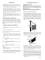
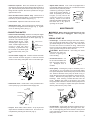
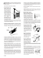
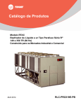
OWNER’S MANUAL
CHAMPION•MARQUIS
EVAPORATIVE COOLER
MODELS
WC 35
WC 43
WC 45
WC 49
CIRCLE THE MODEL OF YOUR
COOLER AND RECORD THE SERIAL
NUMBER BELOW.
ENCIERRE CON UN CIRCULO EL
MODELO DE SU ENFRIADOR Y ESCRIBE
EL NUMERO DE SERIE ABAJO.
READ CAREFULLY ALL OF THIS
MANUAL BEFORE INSTALLING THE
UNIT
SERIAL #
LEA CON CUIDADO TODO ESTE MANUAL
ANTES DE INSTALAR LA UNIDAD
NUMERO DE SERIE
READ AND SAVE THESE INTRUCTIONS
VEA EL ESPAÑOL EN EL INTERIOR.
1. Read these instructions carefully.
2. Electrical hook up should be done by a qualified electrician,
so that all electrical wiring will conform to your local standards.
EVAPORATIVE COOLING
Evaporative cooling is nature’s way of cooling. When air is
moved over a wet surface, water is evaporated and heat is
absorbed. When stepping out of a swimming pool with the
wind blowing, evaporative cooling makes you feel cool, even
though the air may be warm. The human body itself is cooled
primarily by the evaporation of perspiration.
This unit works on the same principle. Air is drawn across
wet filter pads where the air is cooled by evaporation and
then circulated throughout the building. It is this combination
of cooled air and the movement of air over the skin which
makes it feel cool.
Unlike refrigeration systems which recirculate the air, an
evaporative cooler continually brings in fresh air while
exhausting old air. You are completely replacing the air every
2 to 4 minutes by opening windows or doors or a combination
of both. The air is always fresh, not stale, laden with smoke
and odors as happens with refrigerated air conditioning.
110496
SAFETY RULES
3. Unit must be in the OFF POSITION and UNPLUGGED from
power receptacle when installing or performing any maintenance.
4. This cooler will run on 120 volt A.C., 60 Hz (cycle) current
only.
5. Motor and pump are grounded and have an automatic thermal overload switch which will shut motor off when it
overheats. The motor will restart automatically when it
cools down.
6. Pump receptacle is for grounded evaporative cooler pump
only. Do not plug anything else into receptacle.
WARNING: To reduce the risk of fire or electric shock,
do not use this fan with any “solid-state fan speed control device.”
www.championcooler.com
2-03
OPERATION
• Pump setting. The rotary switch has 6 settings. The
“Pump” setting will operate the pump without the blower.
For best results turn the switch to “Pump” for a few minutes to wet the pads before operating the fan.
• High and low cool settings. The “High Cool” and “Low
Cool” settings operate both the pump and the blower.
Turn the unit to “Low Cool” when possible. This lower
speed allows the air to stay longer in the wet pads and
therefore increases it’s cooling efficiency.
• High and low vent settings. The “High Vent” and “Low
Vent” settings operate the blower without the pump. This
is useful on cool nights or at times when just a fan is
desired.
OPEN WINDOWS TO EXHAUST AIR
An often misunderstood concept of evaporative cooling is
the amount of air that should be exhausted. How much
should you open your windows? The fact is that most
people do not open their windows enough. The following
method will help you determine the amount to open your
windows.
COOLER INSTALLATION
MOUNTING COOLER
CAUTION: Make sure that the mounting surface is
strong enough to support the operating weight of the
cooler when in use. (For operating weight, see
Specification Table.)
CAUTION: Never plug in cooler until installation is
complete and unit has been tested for rigidity.
• Lift out all removable louvered sides.
• Screw chain hooks into window facing. Position the
two chain hooks above the neck of the cooler a distance
equal to the width of the cooler apart (A-Fig. 1). Hook
one hanger chain in each hook and then one “S” hook in
the other end of each chain. NOTE: Chain hooks supplied with this mounting kit have wood screw threads for
wood walls. Concrete, brick walls or concrete blocks require sufficiently strong wing nuts or anchors with mating
hooks.
A
“S” HOOK
D
B
C
CHAMPION AIR BALANCING METHOD
1. Take a piece of tissue paper and cut it lengthwise into 3
equal strips.
WINDOW
NECK
H
E
2. Turn your cooler on High Cool.
F G
3. Open one window at least six inches wide in each room
that you want to cool.
4. Take the piece of tissue paper and put it up against the
screen of the open window furthest from the cooler discharge opening. Let go of it. It will do one of three
things.
IF
THEN
It falls down.
CLOSE all of the windows one inch and try step 4
again.
IF
THEN
It plasters itself to the screen.
OPEN all of the windows one inch and try step 4
again.
IF
THEN
It stays on the screen lightly.
PERFECT. You are done. Enjoy your cooler.
NOTES:
• When switching to Low Cool, you must rebalance your
home. Repeat step 4.
• Once you balance your home you can cool some areas
more than others by opening those windows more and
closing the others by the same amount. Repeat step 4 to
make sure your home is still air balanced.
2
FIG. 1
• Install window panel retainers. Place two panel retainer
strips onto bottom of neck flange and position to the width
of the window. Cut the strips to fit if necessary. These
strips hold the window fill-in panels (Fig. 2).
WINDOW FILLIN PANELS
TOP PANEL
RETAINER
BOTTOM PANEL
RETAINER
FIG. 2
• Position cooler in window. Position neck of cooler so
that bottom of neck flange rests on window sill and flange
(E-Fig. 1) is snug against edge of sill (H-Fig. 1). With cooler
in position, hook the “S” hooks into the holes of the top pan
near the back of the cooler (B-Fig. 1).
• Break fill-in panels to fit. With cooler installed, as described above, measure for each window fill-in panel and
score with sharp knife and straight edge guide to desired
width. To break window fill-in panels, the panel should
be laid over the edge of a straight flat surface at the point
to be broken off. Apply pressure on the edge of the panel
that extends over the edge of the surface and break off
unwanted piece.
110496
• Install fill-in panels. Place one window fill-in panel on
each side of grill and into panel retainer strip at bottom of
grill. Place the other panel retainer strips onto top of neck
flange and fill-in panels. Be sure the panels are snug up
against cooler neck.
• Place window behind retainer strip. Raise back of
cooler so that the window (D-Fig. 1) may be brought down
behind top of panel retainer strip (C-Fig. 1).
• Level Cooler. Adjust the chains to level the cooler.
• Adjust house legs. Pull out house legs so that the rubber bumpers rest against house siding (F-Fig. 1). Tighten
screw in retaining collar. (G-Fig. 1).
CONNECTING WATER
• Install overflow assembly. Remove nut and place nipple
through the hole in the pan, with the rubber washer between the pan and the head of the drain nipple (Fig. 3).
Screw on nut and draw up tight
against bottom of pan. Insert
OVERFLOW PIPE
overflow pipe in nipple to retain
NIPPLE
water. Overflow pipe may be reRUBBER WASHER
moved to drain pan when
BOTTOM PAN
necessary. A garden hose may
NUT
be screwed on the drain nipple
FIG. 3
to drain water away from your
unit.
NUT
FERRULE
FAUCET
WATER SUPPLY
VALVE
• Connect water supply line. Install a sillcock and water
valve on faucet as shown by figure 4. Place the nut and
ferrule on the tubing and tighten the nut until water tight.
SILLCOCK
FIG. 4
• Install float valve. Install valve in the provided hole in
corner post (Fig. 5) and attach water supply line.
WATER
SUPPLY LINE
• Adjust water amount. Your cooler is equipped with a
unique water metering valve (Fig. 6). The amount of water
delivered to the pads may be decreased by pressing the plastic
INCREASE
valve as the arrows indicate. If
water is splashing out of water
troughs, you may need to decrease the amount of water
delivery. Check to see that all
DECREASE
pads are saturated with water and
that there are no dry spots or
FIG. 6
openings in the pads.
MAINTENANCE
WARNING: Before doing any maintenance be sure
power is off and unit is unplugged. This is for your
safety.
SPRING START-UP
• Oil bearings. The blower bearings and cooler motor in
this unit should be oiled with a few drops of non-detergent 20/30 weight oil once each year. The motor does
not need oil if it has no oil lines for oiling. Motors that
have no oil lines are lifetime oiled at the factory and require no further oiling for the life of the unit.
CAUTION: Do not over oil. Over oiling can cause
motor burn out, due to excessive oil getting into
3 LB.
motor winding.
3/4 INCHES
• Check belt tension. A 3
lb. force should deflect the
belt 3/4 inches (see Fig.
7).
Readjust belt if
needed.
FIG. 7
• Clean pump. Cleaning the pump is necessary once a
year at start-up. For your safety, turn unit off and unplug
from power receptacle. Remove the pump from the mount
slot. Remove the base of the pump as shown in Fig. 8.
Clean the pump and turn the impeller to ensure free operation. Remove the pump spout and check for any
blockage. After cleaning, reinstall the base onto the
pump. Reattach the pump to the mount in the cooler
using the plastic retainer to ensure that the pump will not
overturn. Do not forget to replace the spout and water
delivery tube onto the pump outlet.
DEPRESS HERE
TO REMOVE
CORNER POST
WASHER
NUT
FERRULE
NUT
FLOAT ROD
FIG. 8
FIG. 5
• Fill pan. Allow water to fill to within 1” of top of pan and
adjust float to maintain this water level. This can be accomplished by bending the float rod (Fig. 5).
110496
• Change Pads. Aspen pads should be replaced once or
twice a season, depending upon the length of the season. At the beginning and at mid season a clean pad is
more absorbent and efficient and will deliver substantially more cool air.
3
By following the operating, installation, and maintenance
suggestions as outlined, you can get many years of efficient
and satisfactory service from your cooler. In the event
additional information is desired, your dealer will be more
than glad to assist you in every possible way.
WINTER SHUT DOWN
• Drain water. Always drain all of the water out of the cooler
and water supply line when not in use for prolonged periods, and particularly at the end of the season. Keep the
water line disconnected from both the unit and water supply so that it does not freeze.
WIRING DIAGRAM
• Cover unit. To protect the life of the finish, a cover for the
unit is suggested in extended periods of non use.
BLOWER MOTOR
• Cover grill. To help keep out cold air you can use the
plastic grill cover provided. Line up the grill cover with the
grill so that the tabs on the cover will slide over the center
section of the grill. Slide the grill cover onto the grill. The
tabs will snap into place. To remove, just pull the grill cover
straight forward away from the grill.
PLUG
HI
LOW
GND
COM.
• Unplug unit from power supply during extended periods of non-use.
SWITCH
BLACK
RED
GREEN
WHITE
PUMP
MOTOR
LIMITED WARRANTY
This warranty is extended to the original purchaser of an evaporative cooler installed and used under normal conditions. It
does not cover damages incurred through accident, neglect, or abuse by the owner. We do not authorize any person or
representative to assume for us any other or different liability in connection with this product.
Terms And Conditions Of The Warranty
For Eight Years from date of installation, we will replace the original base assembly if water leakage should occur due to
rust out.
For One Year from date of installation, we will replace any original component provided by Champion Cooler which fails due to
any defect in material or factory workmanship only.
Exclusions From The Warranty
We are not responsible for replacement of cooler pads. These are disposable components and should be replaced periodically. We are not responsible for any incidental or consequential damage resulting from any malfunction.
We are not responsible for any damage received from the use of water softeners, chemicals, descale material, plastic
wrap, or if a motor of a higher horsepower than what is shown on the serial plate is used in the unit.
We are not responsible for the cost of service calls to diagnose cause of trouble, or labor charge to repair and/or replace parts.
How To Obtain Service Under This Warranty
Contact the Dealer where you purchased the evaporative cooler. If for any reason you are not satisfied with the response
from the dealer, contact the Customer Service Department: Champion Cooler, 5800 Murray Street, Little Rock, Arkansas
72209. 1-800-643-8341. [email protected].
This limited warranty applies to the original purchaser only.
MOT OR SPECIFICAT IONS / ESPECIFICACIONES DEL MOTOR
4
Model No.
Modelo
Motor Part #
Motor - N°
HP
HP
Speed
Velocidad
Volts
Voltios
Motor Pulley Part #
Polea Del Motor - N°
Electrical Cord Part #
Cable Eléctrico - N°
Drive Belt Part #
Banda - N°
WC 35
WC 43
WC 45
WC 49
110442
110442
110442
110443
1/3
1/3
1/3
1/2
2
2
2
2
115
115
115
115
110271
110272
110272
110273
110364
110364
110364
110364
110211 (4L-450)
110210 (4L-500)
110210 (4L-500)
110210 (4L-500)
110496
GENERAL SPECIFICAT IONS / ESPECIFICACIONES GENERALES
Model No.
Modelo
Weight (lbs.)
Peso (libras)
Cabinet Dimensions (in.)
Dimensiones De La Caja (pulgadas)
Window Opening Req'd (in.)
Abertura Requerida (pulgadas)
Dry
Seco
Operating
Lleno
Height
Altura
Width
Anchura
Depth
Profundidad
Width
Anchura
Height
Altura
152
160
170
175
229
237
264
269
33 7/16
39 13/16
39 13/16
39 13/16
28 1/8
28 1/8
34 1/8
34 1/8
28 1/8
28 1/8
28 1/2
28 1/2
21 3/4
21 3/4
21 3/4
21 3/4
14 3/4
14 3/4
14 3/4
14 3/4
WC 35
WC 43
WC 45
WC 49
TROUBLESHOOTING
PROBLEM
POSSIBLE CAUSE
REMEDY
Failure to start or no
air delivery
1. No electrical power to unit
• Fuse blown
• Circuit breaker tripped
• Electric cord unplugged or damaged
2. Belt too loose or tight
3. Motor overheated
• Belt too tight
• Blower bearings dry
4. Motor locked
1. Check power
• Replace fuse
• Reset breaker
• Plug in cords or replace if damaged
2. Adjust belt tension
3. Determine cause of overheating
• Adjust belt tension
• Oil blower bearings
4. Replace motor
Inadequate air
delivery with cooler
running
1. Insufficient air exhaust
2. Belt too loose
3. Pads plugged
1. Open windows or doors to increase air flow
2. Adjust belt tension or replace if needed
3. Replace pads
Inadequate cooling
1. Inadequate exhaust in house
2. Pads not wet
• Pads plugged
• Open spots in pads
• Trough holes clogged
• Pump not working properly
1. Open windows or doors to increase air flow
2. Check water distribution system
• Replace pads
• Repack pads
• Clean trough and unplug holes
• Replace or clean pump (Unplug unit)
Motor cycles on and
off
1.
2.
3.
4.
1.
2.
3.
4.
Noisy
1. Bearings dry
2. Wheel rubbing blower housing
3. Loose parts
1. Oil bearings
2. Inspect and realign (Unplug unit)
3. Tighten loose parts
Excessive humidity in
house
1. Inadequate exhaust
1. Open doors or windows
Musty or unpleasant
odor
1. Stale or stagnate water in cooler
2. Pads mildewed or clogged
3. Pads not wetting properly
• Trough holes clogged
• Pump not working properly
1. Drain pan and clean pads
2. Replace pads
3. Check water distribution system
• Clean
• Replace or clean pump (Unplug unit)
Water draining from
cooler
1. Float arm not adjusted properly
2. Overflow assembly leaking
1. Adjust float
2. Tighten nut and overflow pipe.
110496
Low voltage
Excessive belt tension
Blower shaft tight or locked
Bearings dry
Check voltage
Adjust belt tension
Oil or replace bearings (Unplug unit)
Oil bearings
5
REPLACEMENT PARTS LIST / LISTA DE PIEZAS DE REPUESTO
All parts may be ordered from your dealer, but not directly from the factory. Be sure that you furnish the following information on all
orders. / Todas las partes pueden ser pedidas con su concesionario, pero no directamente a la fábrica. Incluya toda la información siguiente
con su pedido:
1.
2.
3.
4.
Cooler serial number / Número de serie de la unidad
Description and part number / Descripción y número de pieza
Cooler size / Tamaño de la unidad
Date of purchase / Fecha de compra
Failure to supply all of this information will delay your order. / El no proporcionar toda esta información resultará en una demora.
No.
N°
1.
2.
3.
4.
5.
6.
7.
8.
9.
10.
11.
12.
13.
14.
15.
16.
17.
18.
19.
20.
21.
22.
23.
24.
25.
26.
27.
28.
29.
30.
31.
32.
33.
34.
35.
37.
38.
39.
40.
41.
42.
43.
44.
45.
46.
47.
Description / Descripción
WC 35
Top Pan / Tapa ------------------------------------------------------------------------------- 222903-001
Bottom Pan / Base De La Caja ----------------------------------------------------------- 222904-001
Louvered Side / Reja Lateral ------------------------------------------------------------- 224006-003
Louvered Back / Reja Posterior ---------------------------------------------------------- 224006-003
Water Trough, Side / Canal De Agua, Lateral ---------------------------------------- 226003-001
Water Trough, Back / Canal De Agua, Posterior ------------------------------------- 226003-001
Aspen Pads, Side / Filtros De Paja, Lateral ------------------------------------------ 110091
Aspen Pads, Back / Filtros De Paja, Posterior --------------------------------------- 110091
Pad Retainer, Side / Soporte Para El Filtro, Lateral -------------------------------- 3PW-4
Pad Retainer, Back / Soporte Para El Filtro, Posterior ----------------------------- 3PW-4
Corner Post, With Float Hole / Poste De Esquina, Con Agujero Para Flotador 224003-022
Corner Post, No Float Hole / Poste De Esquina, Sin Agujero Para Flotador --- 224003-002
Front Panel / Panel De Frente ------------------------------------------------------------ 224104-001
Tunnel / Túnel (Cuello Del Enfriador) --------------------------------------------------- 322120-001
Blower Housing / Caja De La Rueda ---------------------------------------------------- 324104-002
Blower Wheel / Rueda ---------------------------------------------------------------------- 12BW
Shaft, Blower Wheel / Eje De La Rueda ------------------------------------------------ 110182
Bearings, Blower Wheel Shaft / Cojinetes Del Eje De La Rueda ----------------- 110351
Pulley, Blower Wheel / Polea De La Rueda ------------------------------------------- 110274
Drive Belt / Banda De Transmisión ------------------------------------------------------- 110211
Motor / Motor --------------------------------------------------------------------------------- 110442*
Pulley, Motor / Polea Del Motor ---------------------------------------------------------- 110271
Electrical Cord, Motor / Cable Eléctrico Del Motor ---------------------------------- 110364
Motor Mount / Montura Del Motor ------------------------------------------------------- 314003-001
Motor Mount Clips / Seguros Para Montar Motor ------------------------------------ 314005-001
Float Valve / Flotador ----------------------------------------------------------------------- FL-C
Pump Mount / Montura De La Bomba --------------------------------------------------- 216003-001
Pump Screen / Malla Para La Bomba -------------------------------------------------- 281001-001
Pump Assembly / Bomba ------------------------------------------------------------------ C60P-120
Pump Retainer / Sujetador De La Bomba ---------------------------------------------- 110866N
Connector, Pump Mount / Unión Para La Montura De La Bomba --------------- 3PM-1
Tube, Water Delivery / Tubo De Agua -------------------------------------------------- 310716
Water Flow Control Valve / Válvula Reguladora Del Flujo De Agua ------------- 281013-001
Water Distributor Assembly / Sistema Del Distribuidor De Agua ----------------- 3D-2
Holder, Water Distributor / Soporte Para El Distribuidor De Agua --------------- 110574
Over Flow Assembly / Montaje De Desagüe ------------------------------------------ 3OA-1
Grill Assembly / Rejilla Completa -------------------------------------------------------- 310839-101
Wiring Harness / Cableado Eléctrico ---------------------------------------------------- 110375
Switch / Interruptor -------------------------------------------------------------------------- 110425
Knob, Switch / Perilla Del Interruptor -------------------------------------------------- 110839-006
Grill Cover / Cubierta Para La Rejilla --------------------------------------------------- 110829
House Leg Collar / Collar De La Pata -------------------------------------------------- 3HL-1
House Leg / Pata ---------------------------------------------------------------------------- 310811
Retainers, Window Panels / Guarda De Retención Para Los Paneles ----------- 110600
Window Panels / Paneles De Relleno Para La Ventana ----------------------------- 110601
Switch Box / Caja Para El Interruptor ---------------------------------------------------- 222006-001
WC 43
222903-001
222904-001
224006-004
224006-004
226003-001
226003-001
110089
110089
3PW-4
3PW-4
224003-024
224003-001
224103-005
322120-001
324103-002
15BW
110182
110351
110275
110210
110442*
110272
110364
314003-003
314005-001
FL-C
216003-001
281001-001
C60P-120
110866N
3PM-1
310716
281013-001
3D-2
110574
3OA-1
310839-101
110375
110425
110839-006
110829
3HL-1
310811
110600
110601
222006-001
WC45
WC49
222905-001
222903-004
224006-004
224007-003
226003-001
226003-002
110089
110090
3PW-4
3PW-5
224003-020
224003-003
224105-003
322120-001
324105-102
16BW
110183
110351
110275
110210
*
*
110364
314003-005
314005-001
FL-C
216003-001
281001-001
C60P-120
110866N
3PM-1
310716
281013-001
3D-3
110574
3OA-1
310839-101
110375
110425
110839-006
110829
3HL-1
310811
110600
110601
222006-001
* See motor specification table. / Vea la tabla de especificaciones del motor.
NOTE: Standard hardware items may be purchased from your local hardware store.
NOTA: Artículos de uso corriente pueden comprarse en la ferretería de su localidad.
6
110496
REPLACEMENT PARTS / PIEZAS DE REPUESTO
5
34
1
6
35
4
35
WC LY
N
O
24
12
3
7
9
25
15
32
33
18
23
16
8
19
10
31
30
17
37
20
26
21
29
11
27
28
22
13
2
3
43
24
44
25
14
46
5,
C4
, W NLY
3
4
O
WC C49
W
45
39
40
41
47
38
42
46
45
110496
7
LEA Y CONSERVE ESTAS INSTRUCCIONES
REGLAS DE SEGURIDAD
1. Lea las instrucciones con cuidado.
2. Las conexiones eléctricas deben ser hechas por un electricista competente, para que todo el cableado eléctrico
cumpla con los requisitos establecidos en su localidad.
3. La unidad debe estar APAGADA y DESCONECTADA de
la electricidad cuando se instale o haga cualquier mantenimiento.
• Los posiciones HIGH COOL y LOW COOL. Ajuste el interruptor a la posición HIGH COOL o LOW COOL para poner
en marcha el ventilador a una velocidad alta o baja junto con
la bomba. Ajuste el interruptor a la posición LOW COOL
cuando posible. Esta velocidad baja de la ventilador permite que el aire se queda más de largo en los filtros mojados
y de tal modo produce un aire más fresco.
• Los posiciones HIGH VENT y LOW VENT. Ajuste el interruptor a la posición HIGH VENT (alta) o LOW VENT (baja)
para poner en marcha el ventilador a una velocidad alta o
baja sin la bomba. Este es útil en noches frescas o cuando
se desea un ventilador solamente.
¿CUANTO DEBE ABRIR LAS VENTANAS?
4. Su enfriador funciona sólo con corriente alterna de 120
voltios, 60 Hz. (ciclos).
5. El motor y la bomba están conectados con la tierra, y se
apagarán automáticamente en caso de sobrecalentamiento. Los motores volverán a funcionar cuando se enfrían.
6. Enchufe una bomba del enfriador evaporativo solamente y
nada más al receptáculo de la bomba.
ADVERTENCIA: Para reducir el riesgo de incendio o
toques eléctricos, no use este ventilador con ningún “dispositivo de estado sólido para controlar la velocidad del
ventilador.”
ENFRIAMIENTO POR EVAPORACION
El enfriamiento por medio de evaporación es la manera de la
naturaleza de refrescarse. Cuando el aire se mueve sobre
una superficie mojada, se evapora el agua y se absorbe el
calor. Al salir de una piscina con el viento que sopla usted
se siente fresco, aunque el aire puede ser caliente. El cuerpo humano sí mismo es refrescado principalmente por la
evaporación del sudor.
Este enfriador funciona usando el mismo principio. El aire
se traza a través de los filtros mojados donde el aire se enfría por medio de evaporación y después circula a través del
edificio. Se hace frío de la sensación cuando tiene esta combinación del aire enfriado y del movimiento del aire sobre la
piel.
Un concepto a menudo entendido mal de enfriamiento por
evaporación es la cantidad de aire que debe ser agotada.
Cuánto debe usted abrir sus ventanas? El hecho es que la
mayoría de la gente no abre sus ventanas bastante. Los dos
métodos siguientes le ayudarán.
EL METODO DE EQUILIBRAR EL AIRE
1. Tome un pedazo de papel de seda y córtelo a lo largo en
3 tiras iguales.
2. Ponga en marcha a su enfriador a “High Cool”.
3. Abra una ventana por lo menos seis pulgadas de ancho
en cada sitio que usted desee refrescar.
4. Tome un pedazo de papel de seda y póngalo contra la
pantalla de la ventana abierta más lejos de la apertura del
enfriador. Suéltalo al papel de seda. Hará una de tres
cosas:
SI:
ENTONCES:
Se caiga.
CIERRE todas las ventanas una pulgada e
intente el paso 4 otra vez.
SI:
ENTONCES:
Se queda contra la pantalla con fuerza.
ABRA todas las ventanas una pulgada e intente el paso 4 otra vez.
SI:
ENTONCES:
Se queda ligeramente contra la pantalla.
PERFECTO. Se ha acabado. Goce del aire
refrescante.
A diferencia de los acondicionadores de aire que recirculan
el aire, un enfriador evaporativo trae continuamente por dentro el aire fresco mientras agota el aire viejo. Se reemplaza
completamente el aire cada 2 a 4 minutos, abriendo las ventanas o las puertas o una combinación de ambas. El aire es
siempre fresco, no es viciado, cargado de humo y olores como
ocurre con los sistemas de aire acondicionado a base de
refrigeración.
NOTAS:
• Al poner el enfriador a “Low Cool”, usted debe reequilibrar
el aire de su hogar. Repita el paso 4.
• Al equilibrar el aire de su hogar usted puede refrescar algunas áreas más que otras abriendo esas ventanas más y
cerrando las otras por la misma cantidad. Repita el paso
4. Asegurarse de que el aire de su hogar sea equilibrado.
OPERACION
INSTALACION
• La posición PUMP. El interruptor tiene seis posiciones.
Ajuste el interruptor a la posición PUMP (bomba) para poner en marcha la bomba sin el ventilador. Para mejor resultado
ponga en marcha la bomba por unos cuantos minutos para
mojar los filtros antes de poner en marcha el ventilador.
8
INSTALAR EL ENFRIADOR
PRECAUCION: La superficie en que ha de colocarse
el enfriador deberá aguantar el peso completo de la unidad cuando ésta está en funcionamiento. (Para saber
este peso, vea la tabla de especificaciones.)
110496
PRECAUCION: No conecte el enfriador hasta que la
instalación esté completa y se haya comprobado la estabilidad del mismo.
• Coloque la ventana detrás de la guarda de retención.
Levante la parte trasera del enfriador para que la ventana (Dfig. 1) pueda bajarse y quedar detrás de la parte superior de
la guarda de retención (C-fig. 1).
• Quite todas las rejas de los costados.
PANELES DE
RELLENO
GUARDA DE
RETENCION
SUPERIOR
GUARDA DE RETENCION
INFERIOR
FIG. 2
• Coloque el enfriador en la ventana. Coloque el cuello del
enfriador dentro de la ventana para que la parte inferior de la
pestaña del cuello se asiente en la repisa de la ventana y la
pestaña (E-fig. 1) se ajuste contra el borde de la repisa (Hfig. 1). Con la unidad situado en la ventana, enganche los
ganchos “S” en los agujeros encontrado en la esquina trasera superior del enfriador (B-fig. 1).
• Rompa los paneles de relleno. Con el enfriador instalado según el método de arriba, mida el ancho requerido para
cada panel. Marque el panel con un cuchillo filoso y una regla al ancho correcto. Apoye el panel en el borde de una
superficie lisa y plana y presione sobre la parte del panel
que se extienda sobre el borde de la superficie, para que
se desprenda la parte sobrante.
• Instale los paneles de relleno. Coloque un panel de relleno a cada lado de la rejilla y dentro de la banda de retención
situada en la parte inferior de la rejilla. Coloque las otras
guardas de retención en la parte superior de la pestaña del
cuello y los paneles de relleno. Compruebe que los paneles
queden bien ajustados contra el cuello.
110496
• Ajuste las patas. Saque las patas (F-fig. 1) para que los
topes de hule descansen contra el costado de la pared.
Apriete el tornillo del collar (G-fig. 1).
CONECTAR EL AGUA
• Instale el montaje de desagüe. Quite la tuerca y pase la
TUBO DE DESAGÜE
boquilla por el agujero de la
bandeja, colocando la arandeBOQUILLA ROSCADA
ARANDELA DE GOMA
la de goma entre la bandeja y la
BANDEJA
cabeza de la boquilla (fig. 3).
TUERCA
Coloque la tuerca en la boquilla
y atorníllela hasta que quede
FIG. 3
apretada contra la parte inferior
de la bandeja. Inserte el tubo de desagüe en la boquilla
para retener el agua. El tubo de desagüe se puede quitar
para desaguar el agua de la bandeja cuando sea necesario. Se puede conectar una manguera de jardín a la boquilla
para desaguar el agua hacia otra parte.
• Instale la válvula del flotador. Instale la válvula
en el agujero que se encuentra en el poste de
esquina (fig. 5) y conecte el tubo de agua.
TUERCA
GRIFO
FERULA
• Conecte el tubo de abastecimiento de agua. Instale
la llave de paso y la válvula
de agua en el grifo de agua
según indica la figura 4. Coloque la tuerca y la férula en
el tubo y apriete bien la tuerca para impedir que gotee
el agua.
VALVULA
DE AGUA
• Instale las guardas de retención. Coloque dos guardas
de retención en la parte inferior de la pestaña del cuello y
ajústelas al ancho de la ventana. Corte las guardas si es
necessario. Éstas sujetan a los paneles de relleno (fig. 2).
• Nivele el enfriador. Ajuste las cadenas hasta que el enfriador esté nivel.
LLAVE DE
PASO
FIG. 4
TUBO DE
ABASTECIMIENTO
DE AGUA
POSTE DE
ESQUINA
VARILLA DEL
FLOTADOR
• Llene la bandeja con
agua. Permita que se llene la bandeja con agua
hasta una altura de una
pulgada por debajo del
FIG. 5
borde superior de la bandeja y ajuste el flotador para que mantenga este nivel. Esto
se puede lograr torciendo la varilla para arriba o para abajo
(fig. 5).
ARANDELA
TUERCA
FERULA
TUERCA
• Fije los ganchos en la
A
pared. Ponga los dos
ganchos para la cadena
arriba del cuello del enGANCHO “S”
friador, separados por
D
B
una distancia equivalenC
te al ancho de la unidad
(A-fig. 1). Enganche una
CUELLO
cadena en cada gancho
H
y luego enganche un
E
gancho “S” en cada cadena. NOTA: Los
ganchos que vienen con
ésta unidad tienen rosca
F G
de tornillo para madera
FIG. 1
y son para uso en paredes de madera. Las paredes de concreto o ladrillo requieren
el uso de tuercas mariposas de suficiente fuerza o anclas
con ganchos de acoplamientos.
• Ajuste la cantidad de agua. Su enfriador viene equipado
con una válvula especial que mide el agua (fig. 6). La cantidad de agua que llega a los filtros puede ser disminuida
presionando la válvula de plástico en
el sentido indicado por las flechas.
AUMENTAR
Si el agua se desborda de los canales, puede ser necesario disminuir el
flujo de agua. Revise y vea que toDISMINUIR
dos los filtros estén empapados de
agua y no tengan partes secas o aguFIG. 6
jeros en los filtros.
9
PREPARAR LA UNIDAD PARA EL INVIERNO
MANTENIMIENTO
ADVERTENCIA: Antes de hacer cualquier mantenimiento, compruebe que la unidad esté apagada y
desconectada de la electricidad. Esto es por su seguridad.
PUESTA EN MARCHA EN LA PRIMAVERA
• Cambie los filtros. Debe cambiar los filtros de paja una o
dos veces durante cada temporada, según la duración de
ésta. Al principio y a mediados de la temporada, un filtro
limpio es más absorbente y eficiente y producirá un mayor
volumen de aire frío.
• Limpie la bomba. Es necesario limpiar la bomba una vez
al principio de cada año. Por su propia seguridad, apague
la unidad y desconéctela de la electricidad. Quite el sujetador de plástico de la montura y jale la bomba, deslizándola
hacia usted. Quite la parte de abajo según se muestra en
la figura 7. Limpie la bomba. Dé le vuelta a la hélice para
verificar que se mueve libremente. Quite el pico de la bomba y vea si está obstruido. Vuelva a colocar la bomba en la
unidad y fíjela en su montura con el sujetador de plástico.
Esto impedirá que se
caiga la bomba al
APRIETE AQUI
PARA QUITAR
agua, lo que dañaría el
motor. No se olvide de
volver a conectar el
tubo de agua a la bomba. La bomba contiene
protección en caso de
sobrecalentamiento
FIG. 7
(se apagará automáticamente).
• Lubrique los cojinetes. Los cojinetes de la rueda y el
motor del ventilador deben ser lubricados usando unas gotas de un aceite no detergente de densidad 20/30 una vez
al año. No obstante, los motores sin tuberías para aceite
no necesitan ser lubricados. Estos motores son lubricados
en la fábrica de por vida y no requieren nunca ninguna lubricación.
PRECAUCION: No lubrique demás. El agregar demasiado aceite puede ocasionar que se queme el motor, a
causa del aceite entrando
al interior del motor.
3 LIBRAS
• Drene el agua. Drene siempre toda el agua de la unidad y
del tubo de abastecimiento de agua cuando no use el enfriador durante períodos prolongados, especialmente al fin
de la temporada. El tubo debe quedarse desconectado del
enfriador y del abastecimiento de agua para que no lo congele.
• Cubra la unidad. Para proteger y alargar la vida útil del
acabado, se sugiere cubrir el enfriador durante períodos
largos cuando no sea utilizado.
• Desconecte la unidad de la electricidad cuando no sea
utilizada durante períodos extendidos.
• Cobra la rejilla. Para ayudar a guardar el aire frío de entrar en la casa, usted puede utilizar la cubierta plástica
proporcionada. Alinee la cubierta con la rejilla de modo
que los clips de la cubierta se deslizarán sobre la sección
de centro de la rejilla. Deslice la cubierta sobre la rejilla.
Los clips de la cubierta se encajarán a presión hacia lugar.
Para quitar, dé un tirón con cuidado a la cubierta, quitándola derecho adelante de la rejilla.
Si usted sigue estas sugerencias en cuanto a instalación,
operación y mantenimiento, podrá disfrutar de muchos años
de servicio eficiente y satisfactorio de este enfriador. Si desea más información, su concesionario tendrá mucho gusto
en ayudarle con respecto a cualquier duda o pregunta.
ESQUEMA DEL CABLEADO
MOTOR DE
LA RUEDA
ALTO
BAJO
TIERRA
COMÚN
ENCHUFE
INTERRUPTOR
NEGRO
ROJO
VERDE
BLANCO
MOTOR
DE LA
BOMBA
3/4 PULGADAS
• Compruebe la tensión de
la banda. Una fuerza de 3
libras debe desviar la banda 3/4 pulgadas (véase fig.
8). Ajuste la banda si es
necesario.
10
FIG. 8
110496
LA LOCALIZACION DE AVERIAS
PROBLEMA
CAUSA POSIBLE
REMEDIO
No arranca o no sale
aire
1. No llega corriente
• Fusible fundido
• Cortacircuito desactivado
• Cable eléctrico dañado
2. Banda muy floja o apretada
3. Motor recalentado
• Banda muy apretada
• Cojinetes de la rueda están secos
4. Motor parado
1. Revise la corriente
• Cambie el fusible
• Restablecer el cortacircuito
• Reemplace el cable
2. Ajuste la tensión de la banda
3. Determine la causa
• Ajuste la tensión de la banda
• Lubrique los cojinetes
4. Cambie el motor
Sale poco aire
cuando la unidad
está funcionando
1. Insuficiente abertura para que salga el
aire
2. Poca tensión en la banda
3. Filtros obstruidos
1. Abra las ventanas o las puertas para aumentar el flujo de aire
2. Ajuste la tensión o cambie la banda
3. Cambie los filtros
Enfriamiento inadecuado
1. El agotamiento del aire es inadecuado
2. Los filtros no están mojados
• Filtros obstruidos
• Filtros agujereados
• Agujeros de los canales obstruidos
• Bomba no funciona
1. Abra más las ventanas o puertas
2. Revise la distribución de agua
• Cambie los filtros
• Acomode la paja en el filtro
• Límpielos
• Cámbiela o límpiela (Desconecte la
unidad)
Motor se apaga y se
enciende
1. Voltaje deficiente
2. Demasiada tensión en la banda
3. Eje del ventilador atorado
4. Cojinetes secos
1. Compruebe el voltaje
2. Ajuste la tensión de la banda
3. Lubrique o cambie los cojinetes (Desconecte
la unidad)
4. Lubrique los cojinetes
Hace Ruido
1. Cojinetes secos
2. Rueda roza contra caja de la rueda
3. Partes sueltas
1. Lubrique los cojinetes
2. Inspeccione y alinee (Desconecte la unidad)
3. Apriételas
Demasiada humedad
en la casa
1. Insuficiente salida de aire
1. Abra las puertas o las ventanas
Olor a encerrado, olor
desagradable
1. Agua estancado en la unidad
2. Los filtros tienen moho o son obstruidos.
3. Los filtros son secos
• Agujeros del canal tapados
• Bomba no trabaja adecuada
1. Desagüe y limpie los filtros
2. Cambie los filtros
1. El flotador no se ajusta correctamente
2. El montaje de desagüe se está
escapando
1. Ajuste el flotador
2. Apriete la tuerca y el tubo de desagüe
El agua está drenando
del enfriador.
110496
3. Revise la distribución de agua
• Límpielos
• Reemplace o limpie la bomba (Desconecte
la unidad)
11
GARANTÍA LIMITADA
La presente garantía se extiende al comprador original de un enfriador evaporativo instalado y utilizado bajo condiciones
normales. No cubre daños ocurridos por accidente, descuido o abuso por parte del propietario. No autorizamos que ninguna
otra persona o representante asuma por nosotros cualquier otra o diferente responsabilidad en relación con este producto.
Términos y Condiciones De La Garantía
Durante Ocho Años a partir de la fecha de instalación, nosotros reemplazaremos la base original del enfriador en caso de que
goteara agua debido a oxidación.
Durante Un Año a partir de la fecha de instalación, reemplazaremos cualquier componente original proporcionado por Champion
Cooler que falle debido a cualquier defecto de material o mano de obra en la fábrica solamente.
Exclusiones De La Garantía
No somos responsables por reemplazar los filtros del enfriador. Estos son componentes desechables y deben cambiarse
periódicamente. No somos responsables por daños que resulten a consecuencia de alguna falla de funcionamiento.
No somos responsables por cualquier daño producido por el uso de suavizadores de agua, productos químicos, materiales
desincrustantes, envolturas de plástico, o si se usa en esta unidad un motor de mayor potencia de la que se indica en la placa
de número de serie.
No somos responsables por el costo del servicio para diagnosticar la causa del problema ni por la mano de obra necesaria para
reparar y/o reemplazar piezas.
Como Obtener Servicio Bajo Esta Garantía
Póngase en contacto con el Concesionario que le vendió el enfriador. Si por alguna razón usted no queda satisfecho con la
respuesta por parte del Concesionario, comuníquese con el departamento de servicio al cliente: Champion Cooler, 5800 Murray
Street, Little Rock, Arkansas 72209. 1-800-643-8341. [email protected].
Esta garantía limitada se aplica al comprador original solamente.
12
110496