1
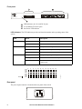
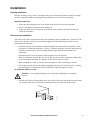
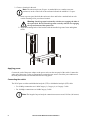
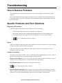
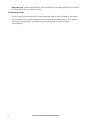
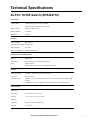
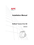
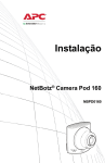
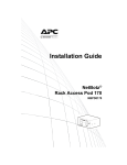
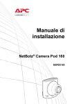
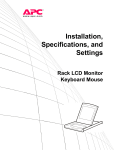
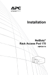
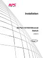
Installation 24-Port 10/100 Ethernet Switch AP9224110 This manual is available in English on the enclosed CD. Dieses Handbuch ist in Deutsch auf der beiliegenden CD-ROM verfügbar. Este manual está disponible en español en el CD-ROM adjunto. Ce manuel est disponible en français sur le CD-ROM ci-inclus. Questo manuale è disponibile in italiano nel CD-ROM allegato. 本マニュアルの日本語版は同梱の CD-ROM からご覧になれます。 O manual em Português está disponível no CD-ROM em anexo. Contents Installation ....................................................................... 1 Preliminary Information . . . . . . . . . . . . . . . . . . . . . . . . . . . . . . . . . . . . 1 Overview . . . . . . . . . . . . . . . . . . . . . . . . . . . . . . . . . . . . . . . . . . . . . . . 1 Features . . . . . . . . . . . . . . . . . . . . . . . . . . . . . . . . . . . . . . . . . . . . . . . . 1 Inventory . . . . . . . . . . . . . . . . . . . . . . . . . . . . . . . . . . . . . . . . . . . . . . . 1 Front panel . . . . . . . . . . . . . . . . . . . . . . . . . . . . . . . . . . . . . . . . . . . . . 2 Rear panel . . . . . . . . . . . . . . . . . . . . . . . . . . . . . . . . . . . . . . . . . . . . . . 2 Installation . . . . . . . . . . . . . . . . . . . . . . . . . . . . . . . . . . . . . . . . . . . . . . . 3 Desktop installation . . . . . . . . . . . . . . . . . . . . . . . . . . . . . . . . . . . . . . 3 Rack-mounted installation . . . . . . . . . . . . . . . . . . . . . . . . . . . . . . . . . 3 Applying power . . . . . . . . . . . . . . . . . . . . . . . . . . . . . . . . . . . . . . . . . . 4 Connecting the switch . . . . . . . . . . . . . . . . . . . . . . . . . . . . . . . . . . . . 4 Troubleshooting.............................................................. 5 How to Resolve Problems . . . . . . . . . . . . . . . . . . . . . . . . . . . . . . . . . . 5 Specific Problems and Their Solutions . . . . . . . . . . . . . . . . . . . . . . . 5 Diagnosing LED Indicator . . . . . . . . . . . . . . . . . . . . . . . . . . . . . . . . . 5 Power . . . . . . . . . . . . . . . . . . . . . . . . . . . . . . . . . . . . . . . . . . . . . . . . . . 5 Incorrect connections . . . . . . . . . . . . . . . . . . . . . . . . . . . . . . . . . . . . 5 Transmission mode . . . . . . . . . . . . . . . . . . . . . . . . . . . . . . . . . . . . . . 6 Technical Specifications ................................................ 7 24-Port 10/100 Switch (AP9224110). . . . . . . . . . . . . . . . . . . . . . . . . . . 7 24-Port 10/100 Ethernet Switch Installation i Installation Preliminary Information Overview The American Power Conversion (APC®) Ethernet Switch (AP9224110) is a multi-port switch that can be used to create high-speed backbone connections among switches, servers, databases, and end stations. The switch fits into any enterprise-level network as an exit to the backbone switch. Features Each switch features: • Automatic MDI/MDIX for all ports • N-way Auto-negotiation • Store-and-Forward architecture • 1U 19-inch rack-mount design • Internal power supply Inventory The Ethernet Switch package includes the following items: • One APC Ethernet Switch • Power cord • Four rubber feet • Rack mount kit – Two brackets – Eight Phillips-head screws • This Installation Manual If any item is missing or damaged, contact APC Customer Support using the phone numbers on the back cover of this manual. 24-Port 10/100 Ethernet Switch Installation 1 Power Ethernet Switch 2 4 6 8 10 12 14 16 18 20 22 24 1 3 5 7 9 11 13 15 17 19 21 23 2 4 6 8 10 12 14 16 18 20 22 24 1 3 5 7 9 11 13 15 17 19 21 23 LNK/ ACT FDX/ COL LNK/ ACT FDX/ COL dmp0019a Front panel LED indicators (two for each RJ-45 port) 24 10/100Base-TX RJ-45 ports One Power LED indicator LED Indicators. The LED indicators provide real-time information on the operating status of the system. Status Description Power Green Power is on. Off Power is not connected. Green The port is connecting with the device. Blinking The port is receiving or transmitting data. Off No device is attached. Orange The port is operating in full-duplex mode. Blinking Packet collision occurred on this port. Off No device is attached or the port is operating in halfduplex mode. LNK/ACT FDX/COL Power LNK/ ACT FDX/ COL LNK/ ACT FDX/ COL 2 4 6 8 10 12 14 16 18 20 22 24 1 3 5 7 9 11 13 15 17 19 21 23 Rear panel AC INPUT 50/60 Hz 100-240V, 0.8A MAX 2 dmp0022a The power input connector is located on the rear panel of the switch. 24-Port 10/100 Ethernet Switch Installation dmp0021a LED Installation Desktop installation Place the switch on a large, clean, level surface with a power outlet nearby. Make sure there is enough clearance around the switch for attaching cables and the power cord, and for air circulation. Attaching rubber feet. 1. Make sure the mounting surface on the bottom of the switch is free of grease and dust. 2. Remove the adhesive backing from the rubber feet. 3. Apply one rubber foot to each corner on the bottom of the switch to protect the switch from shocks and vibrations. Rack-mounted installation The switch comes with a rack-mount kit and can be mounted in an EIA standard size, 19-inch rack. The switch can be placed in a wiring closet with other equipment. When installing the switch, take into consideration the following: • Install the switch in an environment compatible with the maximum ambient temperature (Tma) specified in “Technical Specifications” on page 7. Switches installed in a closed or multi-unit rack assembly can experience a greater operating ambient temperature than the ambient room temperature. • Install the switch in a way that allows sufficient airflow for safe operation. • When you install the switch in the rack, be sure that you do not create a hazardous condition due to uneven mechanical loading. For example, do not use the switch as a shelf. • When installing the switch, review the switch nameplate to avoid overloading the circuits. • Be sure the switch is properly grounded by plugging it directly into a wall outlet or by verifying the ground path if you connect the switch to the power supply through power strips. To mount the switch in a rack: Caution: To avoid equipment damage, use only the provided hardware to install the brackets. dmp0023a 1. Position one bracket to align with the holes on one side of the switch and secure the bracket with the smaller bracket screws. Attach the remaining bracket to the other side of the switch. 24-Port 10/100 Ethernet Switch Installation 3 2. Choose a location for the unit: Note: The unit occupies one U-space. A notched hole (or a number, on newer enclosures) on the vertical rail of the enclosure indicates the middle of a U-space. a. Insert cage nuts (provided with the enclosure) above and below a notched hole on each vertical mounting rail in your chosen location. Warning: Install cage nuts horizontally, with the ears engaging the sides of the square hole. Do NOT install cage nuts vertically with the ears engaging the top and bottom of the square hole. mph0222a b. Align the mounting holes of the brackets with the installed cage nuts. Insert and tighten screws. Applying power Connect the cord of the power adapter to the power socket on the rear panel of the switch. Connect the other end of the power cord to an appropriately-protected power source. Check the power indicator on the front panel to make sure that the switch is receiving power. Connecting the switch The RJ-45 ports use either unshielded twisted-pair (UTP) or shielded twisted-pair (STP) cable. • For 10 Mbps connections use 100Ω Category 3, Category 4, or Category 5 cable • For 100 Mbps connections use 100Ω Category 5 cable Note: The length of any twisted-pair connection must not exceed 328 feet (100 meters). 4 24-Port 10/100 Ethernet Switch Installation Troubleshooting How to Resolve Problems This chapter describes common problems that may occur when using the switch and their possible solutions. First, use the information in this chapter to attempt to resolve a problem. If this information does not resolve the problem, contact APC Worldwide Customer Support using the numbers listed on the back cover of this guide. Specific Problems and Their Solutions Diagnosing LED Indicator If the LNK LED does not illuminate after connection, check the following: • Verify that the switch and any devices attached to it are turned on. • Be sure the connecting cable is plugged into both the switch and its corresponding device. • Verify that the proper cable type is used and its length does not exceed specified limits. See “Connecting the switch” on page 4. Power If the power indicator on the front panel of the switch does not turn on when the power cord is plugged in, the power outlet or power cord may be defective. If the switch loses power after running for a while, check for loose power connections, or power fluctuations at the power outlet. Incorrect connections The switch can auto-detect whether a device is connected with a straight-through or crossover cable. If the RJ-45 connector pins are not properly configured, the link will fail. Faulty or loose cables. Look for loose or faulty connections. Make sure the connections are snug. If that does not correct the problem, try a different cable of the same category. Non-standard cables. Check that you are using the correct cables. See “Connecting the switch” on page 4. Improper network topologies. Make sure that you are using a valid network topology. Too many hubs or repeaters between the connected computers in the network may increase the number of packet collisions or cause other network problems. Remove unnecessary hubs from the network. 24-Port 10/100 Ethernet Switch Installation 5 Data path loops. Check for data path loops. There should be only one cabling path at any time between the switch and the device to which it connects. Transmission mode The RJ-45 ports use auto-negotiation to set the transmission mode to either full-duplex or half-duplex. Verify that each port is set to the same transmission mode used by the attached device. If the attached device operates at half-duplex, the default when auto-negotiation fails, it does not support auto-negotiation. 6 24-Port 10/100 Ethernet Switch Installation Technical Specifications 24-Port 10/100 Switch (AP9224110) Performance Transfer Rate 14,880 packets per second for 10 mbps 148,800 packets per second for 100 mbps MAC Address 4K MAC address table Memory Buffer 1.25 mbits Backplane 4.8 gbps Electrical Input connector IEC-320-C14 Nominal input voltage 100–240 Vac Input frequency 50–60 Hz Power Consumption 18 Watts (Maximum) Communication and Management Protocol CSMA/CD Technology Store-and-Forward switching architecture LED System: Power Per RJ-45 port: Link/Activity, Full-duplex/Collision Physical Size (H x W x D) 44 x 440 x 120 mm (1.73 x 17.32 x 4.72 in) Connector RJ-45: 24 ports Network Cable 10BASE-T: 2 pairs UTP/STP CAT3, CAT4, or CAT5 cable EIA/TIA 568 100 Ω (100 M) 100BASE-TX: 2 pairs UTP/STP CAT5 cable EIA/TIA 568 100Ω (100M) Environmental Temperature Operating 0º C to 45ºC (32ºF to 113ºF) Storage –10ºC to 70ºC (–14ºF to 158ºF) Humidity Operating 10% to 95% (Non-condensing) Storage 10 % to 95% 24-Port 10/100 Ethernet Switch Installation 7 Compliance Standard IEEE 802.1p CoS IEEE 802.3 10BASE-T IEEE 802.3u 100BASE-TX IEEE 802.3x Flow control Regulatory Approvals Product Safety UL/C-UL 60950-1, EN 60950-1, TÜV, CE EMC CE, FCC part 15, EN 55022, VCCI Class A, EN 55024, EN 61000-3-2, EN 61000-3-3, ICES-003 8 24-Port 10/100 Ethernet Switch Installation Radio Frequency Interference Changes or modifications to this unit not expressly approved by the party responsible for compliance could void the user’s authority to operate this equipment. USA —FCC This equipment has been tested and found to comply with the limits for a Class A digital device, pursuant to part 15 of the FCC Rules. These limits are designed to provide reasonable protection against harmful interference when the equipment is operated in a commercial environment. This equipment generates, uses, and can radiate radio frequency energy and, if not installed and used in accordance with this user manual, may cause harmful interference to radio communications. Operation of this equipment in a residential area is likely to cause harmful interference. The user will bear sole responsibility for correcting such interference. Canada— ICES This Class A digital apparatus complies with Canadian ICES-003. Cet appareil numérique de la classe A est conforme à la norme NMB-003 du Canada. Japan —VCCI This is a Class A product based on the standard of the Voluntary Control Council for Interference by Information Technology Equipment (VCCI). If this equipment is used in a domestic environment, radio disturbance may occur, in which case, the user may be required to take corrective actions. この装置は、情報処理装置等電波障害自主規制協議会(VCCI)の基準 に基づくクラス A 情報技術装置です。この装置を家庭環境で使用すると、電波 妨害を引き起こすことがあります。この場合には、使用者が適切な対策を講ず るように要求されることがあります。 Taiwan—BSMI 警告使用者 : 這是甲類的資訊產品 , 在居住的 環境中使用時 , 可能會造成射頻 干擾 , 在這種情況下 , 使用者會 被要求採取某些適當的對策。 Australia and New Zealand Attention: This is a Class A product. In a domestic environment this product may cause radio interference in which case the user may be required to take adequate measures. European Union This product is in conformity with the protection requirements of EU Council Directive 2004/108/EC on the approximation of the laws of the Member States relating to electromagnetic compatibility. APC cannot accept responsibility for any failure to satisfy the protection requirements resulting from an unapproved modification of the product. This product has been tested and found to comply with the limits for Class A Information Technology Equipment according to CISPR 22/European Standard EN 55022. The limits for Class A equipment were derived for commercial and industrial environments to provide a reasonable protection against interference with licensed communication equipment. Attention: This is a Class A product. In a domestic environment this product may cause radio interference in which case the user may be required to take adequate measures. APC Worldwide Customer Support Customer support for this or any other APC product is available at no charge in any of the following ways: • Visit the APC Web site to access documents in the APC Knowledge Base and to submit customer support requests. – www.apc.com (Corporate Headquarters) Connect to localized APC Web sites for specific countries, each of which provides customer support information. – www.apc.com/support/ Global support searching APC Knowledge Base and using e-support. • Contact an APC Customer Support center by telephone or e-mail. – Regional centers Direct InfraStruXure Customer Support Line (1)(877)537-0607 (toll free) APC headquarters U.S., (1)(800)800-4272 Canada (toll free) Latin America (1)(401)789-5735 (USA) Europe, Middle East, Africa (353)(91)702000 (Ireland) Western Europe +800 0272 0272 (including Scandinavia) Japan (0) 36402-2001 Australia 1(800) 652 725 (toll free) New Zealand 0 (800) 333 373 (toll free) – Local, country-specific centers: go to www.apc.com/support/contact for contact information. Contact the APC representative or other distributor from whom you purchased your APC product for information on how to obtain local customer support. Entire contents copyright 2008 American Power Conversion Corporation. All rights reserved. Reproduction in whole or in part without permission is prohibited. APC, the APC logo, and InfraStruXure are trademarks of American Power Conversion Corporation. All other trademarks, product names, and corporate names are the property of their respective owners and are used for informational purposes only. 990-3346-001 *990-3346-001* 7/2008