1
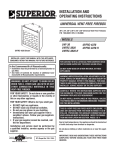
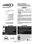
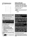
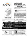
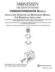
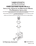
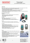
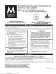
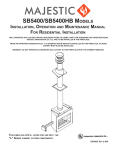
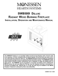
2
CHAPT E R
Installing the Cisco 1005
The Cisco 1005 router is designed for quick and easy installation. This chapter provides
hardware installation procedures and includes the following sections:
•
•
•
•
•
•
•
Safety Recommendations
Inspecting Your Router
Tools and Parts Required
Setting the Router on a Desktop
Mounting the Router
Connecting to the Network and Powering Up the Router
Checking Your Router Installation
It takes just a few simple steps to install the Cisco 1005 router. But before you install the
router, read the safety information in this chapter.
Note Translations of the safety warnings in this document are available in the appendix
“Translated Safety Warnings.”
Installing the Cisco 1005 2-1
Safety Recommendations
Safety Recommendations
Because any device that uses electricity must be handled carefully, follow these guidelines
to ensure general safety:
•
•
•
Keep the area clear and dust-free during and after installation.
•
Wear safety glasses when working under any conditions that might be hazardous to your
eyes.
•
Do not perform any action that creates a potential hazard to people or makes the
equipment unsafe.
Keep tools away from walk areas where you and others could trip over them.
Do not wear loose clothing that could get caught in the chassis. Fasten your tie or scarf
and roll up your sleeves.
Warning Before working on equipment that is connected to power lines, remove jewelry
(including rings, necklaces, and watches). Metal objects will heat up when connected to
power and ground and can cause serious burns or weld the metal object to the terminals.
(To see translated versions of this warning, see the appendix “Translated Safety
Warnings”.)
•
Locate the emergency power-off switch for the room in which you are working. Then,
if an electrical accident occurs, you can act quickly to shut off the power.
•
•
Before working on the system, unplug the power cord.
Disconnect all power before doing the following:
— Installing or removing the router
— Working near power supplies
•
•
•
Do not work alone when potentially hazardous conditions exist.
Never assume that power has been disconnected from a circuit. Always check.
Look carefully for possible hazards in your work area, such as moist floors, ungrounded
power extension cables, and missing safety grounds.
2-2 Cisco 1005 User Guide
Inspecting Your Router
Warning Ultimate disposal of this product should be handled according to all national
laws and regulations. (To see translated versions of this warning, see the appendix
“Translated Safety Warnings.”)
•
If an electrical accident occurs, proceed as follows:
— Use caution; do not become a victim yourself. Disconnect power to the router.
— If possible, send another person to get medical aid. Otherwise, assess the condition
of the victim and then call for help.
— Determine if the person needs rescue breathing or external cardiac compressions;
then take appropriate action.
Warning This product relies on the building’s installation for short-circuit (overcurrent)
protection. Ensure that a fuse or circuit breaker no larger than 120 VAC, 15A U.S.
(240 VAC, 10A international) is used on the phase conductors (all current-carrying
conductors). (To see translated versions of this warning, see the appendix “Translated
Safety Warnings.”)
Warning When installing the main wiring, the ground connection must always be made
first and disconnected last. (To see translated versions of this warning, see the appendix
“Translated Safety Warnings.”)
Inspecting Your Router
Keep the router in the shipping container to prevent accidental damage until you have
determined where you want to install it; then unpack it. Check the packing list to ensure
that you received the following items:
•
•
Cisco 1005 router
Console cable (RJ-45 to RJ-45) with an RJ-45-to-DB-25 adapter
Installing the Cisco 1005 2-3
Tools and Parts Required
•
External power supply with power cord
Note The power cord has the appropriate plug for the country to which the router ships.
•
Label printed with the serial number and Media Access Control (MAC) address, which
is attached to the outside of the shipping container
•
The warranty package, which includes the Product Registration form, service and
support information, and the Ordering Cisco Documentation publication.
Depending on the options you selected, your order might also include the following items:
•
•
•
Optional PCMCIA Flash memory card
Optional network connection cables
Optional companion publications
Inspect all items for shipping damage. If anything appears to be damaged, contact your
system administrator or customer service representative.
Tools and Parts Required
Following are the tools and parts required to install the router:
•
•
•
•
3/16-inch (0.476 cm) flat-blade or socket screwdriver
Wall-mount hardware, including screws, that you provide
Console terminal (a console cable is provided)
One interface cable (not provided) for the LAN port (10BaseT Ethernet)
2-4 Cisco 1005 User Guide
Setting the Router on a Desktop
•
•
One shielded interface cable (not provided) for the WAN port (DB-60 serial)
Channel service unit/digital service unit (CSU/DSU) or modem (synchronous or
asynchronous) (not provided) for access to a WAN
Note To ensure agency compliance, use a shielded serial transition cable with your
Cisco 1005 router when connecting to a CSU/DSU or modem.
The router can be placed on any flat surface or installed in any orientation, such as upside
down or on a vertical surface. It is designed to allow trouble-free operation without cooling
fans, special equipment closets, or racks.
To prevent the cables from disconnecting from the chassis, install your router in a manner
that minimizes strain on the cables.
Setting the Router on a Desktop
To set the router on a desktop, shelf, or other flat, secure surface, perform the following
steps:
Step 1 Confirm that the plastic “feet” on the bottom of the router are turned so that they
are completely under the unit.
Step 2 Set the router on the surface on which you are going to install it, but place it so that
you have access to the rear panel. This orientation will allow you to install the
cables in the connectors on the rear panel.
If you place the router on a desk or table, do not place anything on top of it that
could restrict airflow around the router or weighs in excess of 10 pounds (4.5 kg). Excessive
weight on top of the router could cause damage.
Caution
Installing the Cisco 1005 2-5
Mounting the Router
Mounting the Router
To mount the router on a wall or other flat surface (such as a desk or table), perform the
following steps:
Step 1 Turn out the plastic feet on the bottom of the router to 90 degrees so that the holes
in the feet are exposed. (See Figure 2-1.)
Figure 2-1
Front
H2560
Plastic
foot (4)
Preparing to Mount the Router
2-6 Cisco 1005 User Guide
Mounting the Router
Step 2 Using wall-mount hardware, including screws, that you must provide, attach the
router to a wall or other flat surface. (See Figure 2-2.) Mount the router so that the
following conditions are met:
•
The front-panel LEDs face upward and are easily visible. Later, you will use
the LEDs to verify that the router is working properly. Mounting the router
with the LEDs facing upward will also reduce strain on the cable connections.
•
The power supply does not hang from its cable. The power supply will
disconnect from its cable if it is not supported.
Caution We recommend that you align the plastic feet with a vertical wall stud. If the
screws are not properly anchored in wallboard, drywall, or a vertical stud, cable strain could
pull the chassis from the wall.
Wall-Mounting the Router
OK
RX
H2853
POWE
R
SYSTE
M
SERIA
L
SERIA
LAN
L
COLLI
LAN
TX
RX
TX
OK
SIO
N
LIN
K
Figure 2-2
Installing the Cisco 1005 2-7
Connecting to the Network and Powering Up the Router
Connecting to the Network and Powering Up the Router
After installing the router, install the Flash memory card (optional), connect the interface
cables, and then connect the power supply. All the connectors are on the rear panel of the
router. (See Figure 2-3.) The connectors, from left to right, are as follows:
•
•
10BaseT port (RJ-45)
Console port (EIA/TIA-232) (RJ-45)
Note EIA/TIA-232 and EIA/TIA-449 were known as recommended standards RS-232
and RS-449 before their acceptance as standards by the Electronic Industries Association
(EIA) and Telecommunications Industry Association (TIA).
•
•
•
Serial port (DB-60)
PCMCIA slot (Flash memory card)
DC power input port (12 VDC)
Rear Panel
H3779
Figure 2-3
12VDC
Console
10BaseT
2-8 Cisco 1005 User Guide
Serial
PCMCIA
DC power
input
Connecting to the Network and Powering Up the Router
Installing the Flash Memory Card
This section explains how to install an optional PCMCIA Flash memory card. If you did
not order a Flash memory card, skip this section and proceed to the next section,
“Connecting the Network Interface Cables.”
To install the optional Flash memory (PCMCIA) card, perform the following steps:
Step 1 While pressing down on the two tabs at the top of the PCMCIA door, rotate the
top of the door away from the rear panel, lift it off, and place it aside. (See
Figure 2-4.)
Removing the PCMCIA Door
Tabs
12VDC
H3124
Figure 2-4
Installing the Cisco 1005 2-9
Connecting to the Network and Powering Up the Router
Step 2 If you want to be able to download new software over the WAN, verify that the
Flash memory card is set with write protection OFF. The write-protect switch is
located at the top right edge of the card. (See Figure 2-5.) When write protection
is OFF, the write-protect switch is in the left position, as shown in Figure 2-5.
Figure 2-5
Setting the Write-Protect Switch
Flash card
shown with write
protection off
H2352
Flash card
write protection
Flash card
2-10 Cisco 1005 User Guide
Connecting to the Network and Powering Up the Router
Step 3 Push the Flash memory card into the PCMCIA slot on the rear panel until the
Flash memory card is seated completely in the connector (inside the router). (See
Figure 2-6.)
Figure 2-6
Installing a Flash Memory Card
12VDC
H2842
PCMCIA slot
Flash memory card
Black plastic
eject button
Installing the Cisco 1005 2-11
Connecting to the Network and Powering Up the Router
Step 4 Align the bottom of the PCMCIA door with the bottom of the PCMCIA slot. (See
Figure 2-7.) Then push the top of the door toward the rear panel until the plastic
tabs snap into place. Replacing the door prevents dust from entering the chassis.
Note If you cannot close the door completely, the Flash memory card might not be seated
completely in the connector (inside the router). Press the black plastic eject button at the
right side of the slot (see Figure 2-6) to remove the Flash memory card. Then reinsert the
card and replace the door.
Figure 2-7
Replacing the PCMCIA Door
12VDC
2-12 Cisco 1005 User Guide
H3809
Tabs
Connecting to the Network and Powering Up the Router
Connecting the Network Interface Cables
The 10BaseT Ethernet port supports unshielded twisted-pair cabling. You must supply the
cable that connects to the 10BaseT Ethernet port. To connect your Cisco 1005 router to a
hub, you need a straight-through cable (see Table A-2 in the appendix “Cable Pinouts”). To
connect to a PC Ethernet network interface card, you need a crossover cable (see Table A-3
in the appendix “Cable Pinouts”).
For synchronous communication, the serial port supports the following standard interfaces:
EIA/TIA-232, EIA/TIA-449, V.35, X.21, and EIA-530. For asynchronous communication,
the serial port supports the EIA/TIA-232 standard interface.
You can order from Cisco Systems a DB-60 shielded serial transition cable. The router end
of the shielded serial transition cable has a DB-60 connector; the other end of the cable has
the appropriate connector for the standard interface you specify. (For cable pinouts, refer to
the appendix “Cable Pinouts.”) To ensure agency compliance with electromagnetic
interference (EMI) emissions requirements, use only a shielded serial transition cable with
your Cisco 1005 router.
Do not work on the system or connect or disconnect cables during periods of
lightning activity. (To see translated versions of this warning, see the appendix “Translated
Safety Warnings.”)
Warning
Installing the Cisco 1005 2-13
Connecting to the Network and Powering Up the Router
To connect the network interface cables to the router, perform the following steps:
Step 1 Connect an Ethernet cable (not provided) to the 10BaseT port. (See Figure 2-8.)
Use a straight-through Ethernet cable if you are connecting the router to a
10BaseT hub. Use a crossover Ethernet cable if you are connecting the router to a
PC network interface card.
Warning The ports labeled “10BaseT,” “Console,” and “PCMCIA” are safety extra-low
voltage (SELV) circuits. SELV circuits should only be connected to other SELV circuits.
(To see translated versions of this warning, see the appendix “Translated Safety
Warnings.”)
Figure 2-8
Connecting to the 10BaseT Port
12VDC
Ethernet cable
2-14 Cisco 1005 User Guide
Connecting to the Network and Powering Up the Router
Step 2 Connect the other end of the Ethernet cable to your Ethernet network. You can
connect the Ethernet port in one of two ways:
•
Connect a straight-through 10BaseT cable to a 10BaseT hub. (See Figure 2-9.)
(For cable pinouts, refer to Table A-2 in the appendix “Cable Pinouts.”)
•
Connect the crossover 10BaseT cable to a PC network interface card. (See
Figure 2-10.) (For cable pinouts, refer to Table A-3 in the appendix “Cable
Pinouts.”)
Connecting to a 10BaseT Hub
Cisco 1005
12VDC
10BaseT hub
AUI
8
7
1
Straight-through
10BaseT cable
H3821
Figure 2-9
Installing the Cisco 1005 2-15
Connecting to the Network and Powering Up the Router
Figure 2-10
Connecting to an Ethernet Network Interface Card
Cisco 1005
12VDC
PC
OK
2-16 Cisco 1005 User Guide
H3776
AUX
SER 0
LAN
ETH
Crossover 10BaseT cable
Connecting to the Network and Powering Up the Router
Step 3 Connect a shielded serial transition cable to the serial port. (See Figure 2-11.)
Connecting to the Serial Port
Serial port
12VDC
H3827
Figure 2-11
Shielded serial
transition cable
Installing the Cisco 1005 2-17
Connecting to the Network and Powering Up the Router
Step 4 Connect the other end of the shielded serial transition cable to a CSU/DSU or
modem (synchronous or asynchronous). (See Figure 2-12.) The serial port
operates in data terminal equipment (DTE) mode only. You cannot connect the
cable to another DTE device (such as a router).
Figure 2-12
Connecting to a CSU/DSU or Modem
12VDC
Cisco 1005
Serial port
connector
H3831
Shielded
serial
transition
cable
CSU/DSU or modem
EIA/TIA-232, EIA/TIA-449, V.35,
X.21, or EIA-530 connector
2-18 Cisco 1005 User Guide
Connecting to the Network and Powering Up the Router
Connecting the Console
If your router is not already configured, use the console cable in the console cable kit
provided with your router to connect a console (an ASCII terminal or PC running terminal
emulation software that supports EIA/TIA-232). The console cable kit contains an
RJ-45-to-RJ-45 rollover cable and a RJ-45-to-DB-25 adapter.
To connect a console, follow these steps:
Step 1 Connect the supplied roll-over console cable (RJ-45 to RJ-45) to the console port
on the router. (See Figure 2-13.)
Connecting to the Console Port
12VDC
H3826
Figure 2-13
Roll-over console cable
Step 2 Connect the other end of the console cable to an ASCII terminal or PC. The ASCII
terminal or PC port might require an RJ-45-to-DB-25 adapter. An
RJ-45-to-DB-25 adapter, labeled “Terminal,” is provided with the router. Other
types of adapters are not included.
Step 3 Set your terminal or PC terminal emulation software to 9600 baud, 8 data bits, no
parity, and 2 stop bits.
Installing the Cisco 1005 2-19
Connecting to the Network and Powering Up the Router
Connecting the Power Supply
To connect the power supply, perform the following steps:
Step 1 Connect the DC power cable from the power supply to the DC power input on the
rear panel of the router. (See Figure 2-14.)
Warning This equipment has been designed for connection to TN and IT power systems.
(To see translated versions of this warning, see the appendix “Translated Safety
Warnings.”)
Figure 2-14
Connecting to the DC Power Input
DC power input
12VDC
H3811
Power outlet
Desktop power supply
2-20 Cisco 1005 User Guide
Connecting to the Network and Powering Up the Router
Step 2 Connect the female end of the power cable to the male receptacle on the power
supply. (See Figure 2-15.)
Figure 2-15
Connecting to the Power Supply
DC power input
H3810
12VDC
Desktop power supply
Note The router is shipped with an AC power cable that has the appropriate plug for the
country in which the router will be installed.
Installing the Cisco 1005 2-21
Connecting to the Network and Powering Up the Router
Step 3 Connect the male end of the power cable to the power outlet. Plugging in the
power supply turns ON power to the router. (See Figure 2-16.)
Figure 2-16
Connecting to the Power Outlet
Power outlet
DC power input
H3812
12VDC
Desktop power supply
Warning Unplug the power cord before you work on a system that does not have an on/off
switch. (To see translated versions of this warning, see the appendix “Translated Safety
Warnings.”)
2-22 Cisco 1005 User Guide
Checking Your Router Installation
Checking Your Router Installation
After you finish installing your router, attempt to transfer data and check the LEDs on the
front panel to make sure everything is working properly. (See Figure 4-1 in the chapter
“Troubleshooting the Cisco 1005.”)
Step 1 Make sure that the LED labeled POWER is on steadily, and that the LED labeled
SYSTEM OK is on when the router is plugged into the power source. The system
OK LED blinks during startup and then remains on steadily while the router is
operating. When these LEDs are on, it indicates that the router is receiving power
and that it has passed internal diagnostic tests.
Step 2 Make sure that the LEDs labeled LAN TX (Ethernet transmit) and LAN RX
(Ethernet receive) are flickering, and that the link OK LED is on. When the LAN
TX and LAN RX LEDs flicker, there is Ethernet traffic on your LAN. When the
LAN is very busy, the LED might appear to be on instead of flickering. If the LED
is off, there may be a problem with the unit, or there may be no traffic on the LAN.
When the link LED is on, the router is sensing the Ethernet link signal on the
network. If the link LED is off, the router is not sensing the Ethernet link signal
on the network, and the LAN TX and LAN RX LEDs will be off as well.
Step 3 Make sure that the LEDs labeled SERIAL TX and SERIAL RX are flickering. The
flickering indicates that there is WAN traffic on the serial port. The LEDs might
flicker at intervals of up to 10 seconds, or not at all, depending on the router
configuration and flow of data packets through the router.
If you do not see the correct LED indications, refer to the chapter “Troubleshooting the
Cisco 1005” for more information about the LEDs.
Installing the Cisco 1005 2-23
Checking Your Router Installation
2-24 Cisco 1005 User Guide