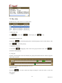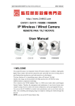
1
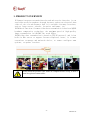
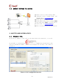
FORWORD This series product is integrated webcam focusing on network video monitoring, including wired box IP camera, wireless box IP camera, wired IR dome camera, wired waterproof IR IP camera, etc. The media processor of camera uses high-ability chip to realize audio/video capture, compression and transmission, the standard Motion-JPEG coding algorithm can confirm the clear and smooth effect of video transmission. The camera supports user remote-real-time monitoring through super client software, system client platform and IE browser, etc. This series IP camera can be used for remote monitoring locations, such as enterprises, chain stores, factories and homes, etc. It is simple pick-up and easy operation. Please confirm the items to be complete, if there is lost, please contact seller timely. ITEMS LIST: IP camera -------------------------------------------- 1piece Bracket(referring to model)---------------------- 1piece Power adapter --------------------------------------- 1piece Certificate------------------------------------------- 1piece CD ---------------------------------------------------- 1piece Warranty card----------------------------------------- 1piece Instruction: IP Camera referred is network camera; PC is personal computer; single click means mouse left click; double click means mouse twice left click. For IP Camera factory settings: Administrator user: admin; password: no password LAN IP address: 192.168.1.126; http port: 81 Statement: The current device may have different version with the sample in this manual, if u can not set up device referring to this manual, please contact provider. The content will update from time to time, the manufacturer reserves the right without notice. -2- MF2E-E-A4 1. PRODUCT OVERVIEW ......................................................................................................... - 4 2. PRODUCT FEATURE ............................................................................................................ - 5 3. DEVICE APPEARANCE AND INTERFACE ........................................................................ - 7 3.1. DEVICE APPEARANCE ............................................................................................. - 7 3.2. DEVICE INTERFACE ................................................................................................. - 7 4. NETWORK CONNECTION ................................................................................................... - 8 4.1. CONNECTION INSTRUCTION ................................................................................. - 8 4.2. ACCESS INSTRUCTION ............................................................................................ - 8 4.3. CONNECT NETWORK VIA ADSL ............................................................................ - 9 4.4. CONNECT NETWORK VIA ROUTER .................................................................... - 10 5. SOFTWARE OPERATION ................................................................................................... - 10 5.1. IPcamera TOOL .......................................................................................................... - 10 5.2. LOGIN IP CAMERA .................................................................................................. - 11 5.3. USER OPERATION ................................................................................................... - 12 5.4. MULTIDEVICE CONFIGURATION ........................................................................ - 13 5.5. NETWORK CONFIGURATION ............................................................................... - 14 5.6. DDNS SETTINGS ...................................................................................................... - 16 5.7. EMAIL SERVICE SETTINGS ................................................................................... - 17 5.8. MOTION DETECTION ............................................................................................. - 18 6. SD CARD GUIDE………………………………………………………………….………_206.1. INSERT SD CARD…………………………………………………………………....-206.2. STORAGE CONFIGURATION……………………………………………………....-216.3. PLAY BACK…………………………………………………………………………..-237. SD CARD PLAYER MANUAL .............................................................................................. -277.1.SYSTEM VEQUIREMENT ...... ……………………………………………………......-277.2 FUNCTION OPERATION ............................................................................................ -277.3.PIAY VIDEO ................................................................................................................. -298. PORT FORWARDING .......................................................................................................... - 31 9. APPENDIX ............................................................................................................................ - 32 9.1. FAMILIAR PROBLEM .............................................................................................. - 32 9.2. WARRANTY .............................................................................................................. - 33 9.3. WARRANTY CARD .................................................................................................. - 34 - -3- MF2E-E-A4 1. PRODUCT OVERVIEW IP Camera integrates network function and web service function, it can send video record to anywhere through internet, and we can view real-time video of site via web browser. And it is suitable for many locations, such as large stores, schools, factories and homes, etc. IPCAM basic function of remote video data transmission is basis on MJPEG hardware compressive technology, the maximum speed of high-quality image transmission in LAN/WAN can reach 25fps. IPCAM video data transmission is based on TCP/IP protocol, and it has built-in Web server to support Internet Explorer, hence, it is more convenient to manage and maintain device, to remote configure some options, to update versions. Please check the product if the items are complete before set-up, if there is some lost, please contact seller. -4- MF2E-E-A4 2. PRODUCT FEATURE ● powerful high-speed processor of video protocol ● high sensitivity and definition CMOS sensor ● 0.3 megapixels ● IR night version ● Optimized Motion-JPEG video compression algorithms to achieve narrow bandwidth high-definition image transmission ● multilevel users and password management ● support many browsers(IE browser,Firefox browser,Google browser, etc.) ● support wireless network(Wi-Fi/802.11/b/g) ● support dynamic DNS (DDNS) ● support maximum 32G SD card storage,for alarm snapshot and record ● support motion detection ● support two-way audio monitoring ● support snapshot ● support mobile phone view ● support log ● support multiprotocol :HTTP/TCP/IP/UDP/STMP/DDNS/SNTP/DHCP/FTP -5- MF2E-E-A4 System feature System security Three levels account, password,multi-authority management Own dynamic IP domain name system(free) Built-in independent R&D DDNS system, lifetime free proprietary ddns, no need to apply DynDns, no worry about frequent offline problem, quickly connection. For example,http://demo.easyn.hk, the serial number is "demo" No need to install software, support IE multi-view, Mobile phone management, phone message on alarm, alarm picture platform(free) storage functions. Superiority Support computer monitoring, support many smart phone in market, such as Iphone, android, Symbian, etc. Mobile phone view Support Iphone、Windows Mobile、Symbian、Android direct view. Local storage Support maximum 32G SD card memory OS Kernel Video Network Alarm Certificate Embedded Linux OS Micro processor 32Bit RSIC Embedded Processor Compression Motion-JPEG-N Signal system CMOS 0.3 megapixels Frame rate 25fps Resolution VGA(640*480),QVGA(320*240) QQVGA(160*120) Image adjustment Brightness, contrast, can be adjusted White balance, BLC Auto white balance and BLC Interface RJ-45 Protocol Support TCP/IP,HTTP,ICMP,DHCP,FTP,SMTP,PPPoE,etc Wi-Fi WIFI,802.11 b/g/n Online user Support 15 users direct connection Support IP Static IP, dynamic IP, PPPOE Input/output 1/1 Alarm detection Motion detection, sensitivity configuration Alarm notice Support to upload pictures via Email, FTP and call preset position, and control by GPIO signal, etc. Certification 10/100Mb auto-adjusted internet interface ISO FCC CE SASO RoHS -6- MF2E-E-A4 3. DEVICE APPEARANCE AND INTERFACE 3.1. DEVICE APPEARANCE Picture 1- device appearance 3.2. DEVICE INTERFACE SD card Picture 2- device interface Power: connect to external power adapter, standard: DC 5V/2A RJ 45: network interface standard: 10/100M auto-adjusted internet interface, it can connect many kinds of devices, such as hub, router, and switch, etc. Network lens: lens flickers when network connecting Power lens: lens on when power on SD card: support 32G SD memory card I/O interface: 1 channel alarm input, connect 3 and 4 interfaces(ground, trigger by low electric level);TTL to control output, connect 1 and 2 interfaces(1,2 short connection). -7- MF2E-E-A4 4. NETWORK CONNECTION Picture 3- network connection scheme 4.1. CONNECTION INSTRUCTION Before access IP Camera, first to confirm the network connection and the power supply, to check if the status lens normal. For connection as picture 3: 1)camera-1 and camera-2 is connected to two different LANs 2)the two LANs must connect to internet and have routers connecting through ADSL or optical fiber, etc. 3)computer-3 should be a device connecting to internet 4.2. ACCESS INSTRUCTION For accessing camera, in addition to communication links remain open, it also requires a simple settings for camera and network: 1)computer and camera are in the same LAN For access IP Camera via LAN, it should be confirmed that the computer and camera in the same subnet, if they are not, then need to configure the IP Camera, for example: in picture 5 camera-1’s IP is 192.168.1.126 (located in subnet 192.168.1),PC-1’s IP is 192.168.0.100(located in 192.168.0),on this case, PC-1 can not access IP Camera-1, after changing IP Camera-1’s IP into 192.168.0.126, it can access; 2)computer and camera are in different LANs, but both of them can access internet. -8- MF2E-E-A4 For camera-1 and computer-2 in picture 3, to access camera-1 through computer-2, then need to set step 1)first to confirm computer-1 can access camera-1, then configure router-1 ( router-1 should support port forwarding), then computer-2 can apply to access camera-1 via router-1. Normally, computer-2 only can send message to router-1, so it can not access camera-1 without configuration of router-1. 4.3. CONNECT NETWORK VIA ADSL Connect device to computer via cable. Configure device basic settings through IP Camera tool (details refer to: 5.1 IPcamera tool). Login device as administrator, access PPPOE setting page to input account user and password. Meanwhile to enable DDNS server function then click <set> to restart device.(details refer to: 5.6 ddns settings) Connect device to internet via ADSL, then it can be accessed via ddns through WAN. -9- MF2E-E-A4 4.4. CONNECT NETWORK VIA ROUTER 1) Connect device to LAN through cable 2) Configure device through IPcam tool. (Details refer to: 5.1 IPcamera tool) 3) Access device as administrator. 4) Access ddns setting page to enable DDNS service then click <set> to restart device. (Details refer to: 5.6 ddns settings) 5) Then it can be accessed through internet. 5. SOFTWARE OPERATION 5.1. IPcamera TOOL In picture 3, camera-1’s IP is not in the same subnet with computer-1, it can not be accessed, to run Devfind.exe in CD, click search button then click-on searched IP Camera, then we can configure the settings, inte rface as picture 4. Picture 4- LAN configuration interface - 10 - MF2E-E-A4 Notice: device factory set IP: 192.168.1.126,port 81 Detail configuration: Please carefully check current computer information on right down side of interface, it lists information about computer-1’s IP configuration, if there are more network adapters in computer, please select the right network that camera-1 working on. IP address: configure IP address, it must confirm to be the same subnet within PC. Mask: default mask: 255.255.255.0 Gateway: confirm the PC within the same gateway DNS: DNS provider’s IP address Port: device provides HTTP service port, default is 81 User and password: default administrator account user: admin, no password 5.2. LOGIN IP CAMERA We can directly access IPCAM through IP Camera Search Tool or IE. 1) Double click option IE in device list to open login page 2) Directly access via IE by inputting address on address blank of IE browser. As below: Picture 5 login interface After installation, we can access video view page, as picture 7: - 11 - MF2E-E-A4 5.3. USER OPERATION If the pilot is Click to 4-picture view; click Record: click Snapshot: click Listen: click , it means the device is connecting network to 9-picture view to manually record to snapshoot picture , it should turn ,then speak to camera, the sound can be heard from computer terminal, click again to close listen function - 12 - MF2E-E-A4 Talk: click ,it turns , talk to camera(through headset connecting computer) ,then we can hear the talking around camera. Click again to close talk function. 5.4. MULTIDEVICE CONFIGURATION On multi-device configuration page, we can see all devices in the LAN. The first device is default device. We can add more devices listing in the device list. It can support 9 pieces of devices on line at the same time for embedded system. Click “the second channel device” then double click on device option, name, host address and Http port of “current LAN devices list” , the information will be auto wrote in, then correctly input access user name and password then click “add”. Repeat that to add more devices. Notice: do not forget to click save for configuration Picture 7- multi-view configuration - 13 - MF2E-E-A4 Picture 8- 4-picutre Picture 9- 9-picture 5.5. NETWORK CONFIGURATION BASIC NETWORK CONFIGURATION IP address configuration: manually modify IP, mask, gateway, DNS, etc. Http port: normally, the default port is 81. If the internet provider block the port, we can set others(range: from 0 to 65535),such as 8080,85, 8888, etc. - 14 - MF2E-E-A4 Picture 10- network configuration WIFI CONFIGURATION To enable WIFI configuration referring to picture 11,click “Search” button,then will pop up a page of searched wireless network,select the right wireless network,then all parameter of the wireless network will auto write into the parameter blanks such as shown in picture 11(such as SSID, encryption, etc.) ,then input password and check it is ok. After configuration,click “Save & restart” button; Notice: the wireless function should be enabled on wired condition Picture 12- WIFI configuration - 15 - MF2E-E-A4 5.6. DDNS SETTINGS In picture 3,router-1 acquire external IP address through ADSL,and the IP address is dynamic,when we want to access device from internet,we do not know what is the IP address,hence,we should acquire the address via dynamic domain name server in internet,the camera-1 send a message to dynamic domain name server(ddns) from time to time,then the ddns can analyze the external IP address of the router-1 camera-1 connected,we can acquire the IP address of the server through dynamic domain name. Actually,the dynamic domain name stands for dynamic IP address,if we can not access device through IP address, the dynamic domain name is not available. MANUFACTURER DDNS The manufacturer has set up ddns in internet,and provide a dynamic domain name for each device,and the settings has been done when the device produced,such as shown in picture 13. After set remote configuration,input the dynamic domain name in browser address blank, then the address will be analyzed as the right IP address of device,and start to connect device. Picture 13- DDNS configuration Notice: the dynamic domain name uses forwarding mode to access device, it auto changes into the IP address and port relating to device. Notice 2: on it can access device via IP address but not dynamic domain name condition,please check the DNS configuration whether it is available and confirm the configuration is attaching with LAN configuration in computer. THIRD PARTY DDNS ACCESS If it is some reason that can not use the manufacturer ddns,we also can apply third party ddns as instead,such as www.3322.org domain system, login this kind of web to apply a free dynamic domain name,then input information as shown in picture 14,after save, then we can access with the dynamic domain name. Notice: usually, third party ddns uses analyzing mode to access device, - 16 - MF2E-E-A4 it will keep the link still after inputting on browser,if device port is not 80,then need to add a”:” then the port behind dynamic domain name,such as: http://ipcam.3322.org:81 5.7. EMAIL SERVICE SETTINGS Input email server Input sender email Input receiver email Login name Login password After save, click to test Click to save Picture 14- email service configuration In picture 14, the configured content is must,if that information is not correct,then the configuration is failed. Notice: before configuring this page, please confirm the email information is available. SMTP server: input the SMTP server of email server Sender address: input email address to send email Receiver address: input email address to receive snapshots and IP - 17 - MF2E-E-A4 address. It can support 4 receivers. 5.8. MOTION DETECTION Select motion detection to monitor a fixed area, it will trigger alarm when there is abnormal situation. The configuration interface as picture 22,device can support 16 areas of motion detection,tick on option under viewing window to enable the function of selected area. After enabling the area,the screen will show a area frame and area number,click mouse on the frame to drag to anywhere,also the frame size can be changed by dragging the right-down corner of the frame. After configuration, click apply button to enable the settings. Picture 15- motion detection Motion detection area: it can trigger email alarm and record linkage after enabling motion detection, and support 16 different areas Sensitivity: it supports to choose different sensitivities from 0 to 30, 30 is the highest. Motion detection alarm: email alarm linkage, FTP upload picture, siren, etc. GPIO input alarm: support external alarm sensor,it can trigger alarm linkage when alarming, such as email notice, FTP upload picture, etc. - 18 - MF2E-E-A4 Picture 16- motion detection configuration 6 SD card guide 6.1. Insert SD card A. Insert SD card to camera SD card interface, as Picture(1-1) showed. SD card Picture (1-1) B. No SD card. Access camera web configuration page, storage option, as Picture(1-2) - 19 - MF2E-E-A4 Picture(1-2) C. Inserted SD card. As Picture(1-3) It will show SD card size information. Picture(1-3) 6.2. Storage configuration - 20 - MF2E-E-A4 Support three modes(no record, continuous record, record on schedule). Normally, 1G SD card size can support to record 2.5 hours on VGA resolution. Continuous record: provide complete record file but limited by SD card size. Record on need: only record following schedule, support longer time record, but can not provide record file for all time. The remaining size of SD card needs to notice, and user can select whether enable cycle record mode. When enable cycle record, the new record file will cover the former record file, the not-covered record file will be saved, and the record file system can fix time as second point. It is our special record file system's advantage. A. No record mode: disable SD record function. As Picture(2-1) Picture(2-1) B. Continuous record mode: when enable this mode the record is running when camera is working. And it can support cycle record mode and alarm on full record mode. As Picture(2-2): Picture(2-2) C. Record on need: support offline record(when camera lost network connection alarm and record) and cycle record control for 24 hours, configure record mode for each hour on need, there are four modes for such configuration: - 21 - MF2E-E-A4 Picture(2-3) 1> no record 2> record for specified hour 3> record when motion detected once 4> record on IO event once 5> record on motion detection or IO event(motion detection or IO input) Picture(2-4) For example, set 7-12 o'clock motion detection(record time is 10 seconds), 13-16 o'clock GPIO alarm(record time is 20 seconds), 17-20 o'clock continuous record, the configuration should be as below: - 22 - MF2E-E-A4 Picture(2-5) 6.3 Playback A. How to download record file from SD card or playback online? We can download record file from SD card through function button on playback option of camera web configuration page to computer, default path is C:\ driver, or we can choose save path on pop-up dialog. The player RealPlayer can support to play the .avi file. B. How to playback record file in SD card? After download record file to computer following "A" mentioned, we can playback record file with speed-up/speed-down mode. Or select specified time point to view record. - 23 - MF2E-E-A4 Picture(3-1) C. Play record file in SD card by SDCardPlayer in CD. Before remove the SD card, please access storage configuration page, click delete SD card button,then unplug the SD card. As Picture(3-2) Picture(3-2) Insert SD card to reader, then connect to computer USB interface. Play record file with SDCardPlayer in CD. Run software then click button in Picture(3-3): - 24 - MF2E-E-A4 Picture(3-3) Select record file in SD card, as Picture(3-4) Picture(3-4) The record files will list on right site, and right down site is record file's time including hour and minute, select time point to play specified record. As Picture(3-5) - 25 - MF2E-E-A4 Picture(3-5) Support forward play most to 32X, click buttons as red arrow specified in Picture(3-6) Picture(3-6) - 26 - MF2E-E-A4 Note: if the record file is big size, online playback or download file from SD card will get a slow speed, recommend to remove SD card then read record file with SDCardPlayer. 7 .SD card player manual 7.1.system requirement Operation system: Windows XP Professional or updated operations system CPU:Intel Core 2 Q8000 or more Memory: Windows XP 1GB or more Resolution: min 1024x768 7.2 Function operation( support MotionJpeg vedio only) 1). Double click to run the program as below photo 2.) Click button , it will show window as below: - 27 - MF2E-E-A4 Choose the SD card disk, then click Apply button, it will play the first video in the SD card( if there are videos in the SD card). It will show all the video list on top right corner as the photo below: It shows the timing when playing, for example: when it is playing the first video(it is listed on the first place on top right corner), if there are some green marks on the time banner, it means there are videos on these time. As below photo: As the above photo shows, it means there is a video between 17:26-17:27 3) The date will show on the date control window, as below photo (note: the above date is the chosen video’s date. For example: choose the SD card it will play the first video automatically. You can see it from step 1), the first video’s date is 2012-Jan-14, that’s why it show like that. 4). SD card’s information SD card information includes roll number, total volume (note: there is a little difference between the total volume and the real volume, because some SD card take 1024 byte and 1Kb, while some take 1000byte and 1Kb),FAT32 district’s balance volume and total volume, record district’s volume and total volume. As below photo: - 28 - MF2E-E-A4 7.3 Play video Double click any video in the list. As below photo 1. Pause, play, stop Click to pause, click to continue play, click to stop. 2. Accelerate, decelerate play Click button button to accelerate playing( note: accelerate playing is not too much effect). Click to decelerate playing. 3. single play, jump play 1)Click button to single play video. Click once ,it play one frame video. Click to come back normal playing. 2)jump play Click the concerned place on the time banner( the green period means there are videos) to play the video of the very time. As the above photos shows, the chosen time is 13:36 4. photo overturn Click button , it can the overturn the image 180 degrees. Click once more, it will come back normal. 5. snapshot - 29 - MF2E-E-A4 Click button , it can snapshot the playing video( note: the photo’s save path can be checked by click the button ). 6. setting click button , it will show path setting as below window. Backup File Path is for setting video save path. Snapshot path is for setting the save path after snapshot. 7. video backup Click the videos which you want to backup in the list and below photo: Then click button , they will be saved as AVI file in the save path. You can see the backup schedule on banner under video. As below photo. (note: please do not click any button when it is backuping, and it will stop the playing video. Double click the video after backup, then you can see the video). 8. SD card formatting Click button , it will show SD card window as below photo: - 30 - MF2E-E-A4 Firstly, choose the SD card Roll NO, then it will shows the SD card’s information on the right side. If click quick, it will format quickly, or it will need more time. It is finished formatting when the schedule banner shows 100%. ( note: click button format, it will show format confirmation window twice. If there are some videos which have no backup, please backup) 9. language The software supports the English and Chinese(PRC).Click Button ,it will popup the Language choose menu. 10. window minimize and come back Click button click tray icon , SD card player will minimize to bottom right corner tray , double , it will come back SD card player window. 11. exit Click button , it will exit SD card player. If it is mini status, right click tray icon , it will show Exit list, click ‘Exit’ to exit. 8. PORT FORWARDING According to picture 3, we can access camera-1 through computer-1, in order to enable computers in internet(such as computer-2, computer-3)to access camera-1,it need to set the camera exposing in internet through configuring port forwarding in router-1 to set the camera to be available to access internet. Access router configuration interface through computer-1,for different model of router it has different interfaces. Hence the configuration ways are some different, - 31 - MF2E-E-A4 please refer to router’s manual. For most routers,we can find option as virtual server settings,input camera-1 IP address and port. As below: Notice: for more IP Camera devices,it needs to set port forwarding for each one, and as distinguishable,we should set different IP and port for each device. If the port is not 80,we should access device by adding a “:” and device port behind the IP address, such as:http://219.134.170.92:81 9. APPENDIX 9.1. FAMILIAR PROBLEM What could we do when forgot the login password? On power condition,press reset button(on the device bottom)till 10 seconds, then device is set to factory settings,including administrator user and password. Default user: admin Default password: no password What could we do when the view screen is white? Please adjust video parameters of camera(mode, brightness, contrast, saturation, etc.). - 32 - MF2E-E-A4 If the back light is too strong,please adjust the monitoring angle Why the camera finder can not search device? Please check whether the device and camera finder are in the same local network; and cable or power problem will cause such problem【 normally,power lens (yellow)is always on, network lens(green)is always flashing】;and the firewall will block the software to run too. Why the device can not access from remote location? 1)Does it can access via LAN?if it is available, then check the access user and password; 2)Check the port forwarding in router; 3) For remote access, the device should be set as a virtual server to wide area network; does the router provide an external IP for port forwarding? 9.2. WARRANTY a) Free warranty one year. In free warranty time, to enjoy free warranty service with warranty card(not for man-made damage). Over warranty time, it needs to pay for maintain cost. b) For improper use caused or other reason or no warranty problem, it enjoys free maintain but paying for parts exchange. c) Send product with warranty card to manufacturer or seller for maintain. d) Privately open device shell and tear up seal affixed label are not in warranty permission. e) Device with modification or extra-installation function is not acceptable. The following circumstances without warranty a) Normal wear and tear caused periodic check, maintains or parts exchange. b) Damage caused by fall, squeezing, man-made flooding, damp and other man-made reasons. c) Damage caused by disaster or human-unstoppable reasons. d) Device maintained by non-authorized repair centers. About above listed,modifying refers to relating rules. - 33 - MF2E-E-A4 9.3. WARRANTY CARD Please cut the below form for information and return with device Product model Manufacture date Client agency User name User address Contact (TEL/mobile phone) maintain time Problem details result note: - 34 - MF2E-E-A4