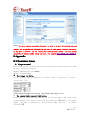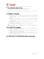
1
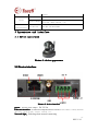
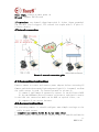
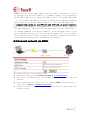
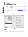
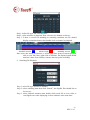
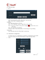
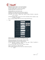
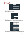
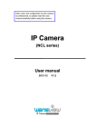
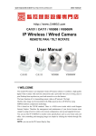
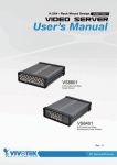
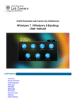
MH3E-E-A1
For
Foreeword
This series product is specific on network video surveillance including wired box
ip camera, wireless box ip camera, wired dome ip camera wired IR waterproof ip camera,
etc. It uses processor with high-performance chips to realize audio/video capture,
compression, transmission, and the standard Motion-JPEG coding algorithm can
confirm the clear-fluent effect of video transmission. It supports user to view
real-time video and remote control via browser such as IE, super client software
and APP platform.
The series IP camera is available to enterprises, chain store, factory, home and
any place need to monitor and view through internet. It is easy to install and
user-friendly operate.
Please check if the accessories are all in before installation. If there is any
missing, please contact seller timely.
List of items:
IP camera --------------------------------------------1 pc
Bracket(refer to model)------------------------------------- 1 pc
Power adapter -------------------------------------------- 1 pc
Certificate------------------------------------------------- 1 pc
CD--------------------------------------------------- 1 pc
Warranty card--------------------------------------------------1 pc
Instruction:
IP Camera it is network camera;PC it is computer;single click:left click of mouse;
double click:double left click of mouse.
IP Camera default administrator user name: admin,password: admin
Default LAN(local area network)IP address:192.168.1.126, port:81
Statement:
The device’s version in the manual may be different from the current device’s version,
if the installation can not finish referring to the manual, please contact seller.
The manufacture preserves authority of content update from time to time.
-1-
MH3E-E-A1
Foreword.......................................................................................................................................- 1 2 Features.................................................................................................................................. - 3 3 Appearance and interface.................................................................................................. - 5 3.1 Device appearance.................................................................................................... - 5 3.2 Device interface.............................................................................................................. - 5 4 Network connection...................................................................................................................- 6 4.1 Connection instruction.................................................................................................... - 6 4.2 Access instruction........................................................................................................... - 6 4.3 Connect network via ADSL............................................................................................ - 7 4.4 Access network through router.............................................................................- 8 5.Software operating.................................................................................................................. - 8 5.1 IPcamera tool.................................................................................................................. - 8 5.2 Login device................................................................................................................... - 9 5.3 Operations................................................................................................................ - 10 5.4 Basic network configuration......................................................................................... - 11 5.5 DDNS configuration..................................................................................................... - 12 5.6 E-mail service configuration.............................................................................- 14 6 Central Management............................................................................................................ - 14 6.1 Installation............................................................................................................ - 14 6.2 Installation steps................................................................................................. - 15 6.3 Login and Logout..........................................................................................................- 15 6.4 Software interface.................................................................................................- 16 6.5 Device management.................................................................................................. - 18 6.6 Image preview.......................................................................................................... - 21 6.7 PTZ control.............................................................................................................. - 23 6.8 Video management.................................................................................................... - 25 6.9 Playback.................................................................................................................... - 29 6.10 Electron map............................................................................................................... - 31 6.12 User management.................................................................................................... - 35 6.13 Log..............................................................................................................................- 36 6.14 Other settings...................................................................................................... - 37 7 Port forwarding.................................................................................................................. - 37 8 Appendix..................................................................................................................................- 38 8.1 Common issue...............................................................................................................- 38 8.2 Warranty instruction.............................................................................................- 39 8.3 Warranty card.......................................................................................................... - 40 -
-2-
MH3E-E-A1
1 Product Overview
IP Camera is designed as web server running on network, it can transmit
real-time video to anywhere through internet, and user can view real-time
live video via web browser any time. It is available to large stores,
schools, factories, houses, etc.
Basic function: IPCAM can transmit real-time live video data to remote
place through internet with hardware compression method MJPE which
providing high-quality video image and 25fps frame rate on LAN/WAN (local
area network/wide area network).
The IPCAM video data transmission is basic on TCP/IP protocol, built-in
web server supporting Internet Explore, thus,it make more easy to manage
and maintain devices to remotely configure, start and upgrade firmware,
etc.
Please check if the items are all in before installation of IP camera, if there
is some missing, please contact seller
2 Features
● powerful high speed video protocol processor
● high sensitive and high definition CMOS sensor
● 0.3 megapixels resolution
● IR night vision
●Optimized Motion-JPEG video compression algorithm, realize to transmit
high definition image through narrow bandwidth
● multiuser management and password
● support browser(IE browser,Firefox browser,Google browser, etc)
● support wireless network(WiFi/802.11/b/g)
● support dynamic DNS (DDNS)
-3-
MH3E-E-A1
●
●
●
●
●
●
●
support max size 32G SD card,snapshot and record on alarm
motion detection
support two-way audio
image snapshot
support mobile phone view
log
support network protocols: HTTP/TCP/IP/UDP/STMP/DDNS/SNTP/DHCP/FTP
System feature
Core
Video
security
Three-level account, password and user authority
management
Built-in ddns
(free)
Built-in unique lifelong free DDNS,no need Oray,
no worry about frequent offline and good speed.
Such as http://demo.ipcam.hk, the series number
is "demo"
Mobile phone
platform
(free)
No need to install software,IE multi-view and
management,snapshot alarm picture, etc
Superiority
Support computer monitoring,support most smart
phone such as Iphone,android, Symbian.
Mobile phone
view
Support Iphone、Windows Mobile、Symbian、Android
directly viewing
Local memory
Support 32G SD card local memory to alarm
snapshot and record
OS
Processor
32Bit RSIC Embedded Processor
Compression
H.264 main profile level 3, main stream and
second stream
Signal system
CMOS
Frame rate
Main stream:1~25 fps,second stream:1-25 fps
Resolution
VGA(640*480),QVGA(320*240)
Image
adjustment
Brightness, contrast, adjustable
BLC
Network
Embedded Linux OS
0.3 megapixels
QQVGA(160*120)
AUTO
Interface
RJ-45
10/100Mb self-adaptable Ethernet slot
Protocol
Support TCP/IP、HTTP、ICMP、DHCP、FTP、SMTP、
PPPoE, etc
Wifi
WIFI,802.11 b/g/n
Online user
Support 10 users directly access at the same time
Support IP
Static ip, dynamic IP, PPPOE
Input/output
One channel linear/Mic input, one channel audio
-4-
MH3E-E-A1
output
Alarm
Certification
Alarm detect
Motion detection, sensitivity configuration
Alarm linkage
Support Email, FTP upload image, call preset
position, GPIO control, etc.
Certificate
ISO FCC CE SASO RoHS
3 Appearance and interface
3.1 Device appearance
Picture 1- device appearance
3.2 Device interface
Picture 2- device interface
power:external power adapter DC 5V/2A
Ethernet interface
interface:10/100M self-adaptable Ethernet interface,can connect to many network
devices, such as hub, router, switch, etc.
Network light:flickering when network connecting
-5-
MH3E-E-A1
Power light:always on when power on
SD card:support 32G SD card
I/O interface:one channel alarm input with 3,4 pins(input grounded,
low electric level trigger);TTL control for output with 1,2 pins(1,
2 short-circuit).
4 Network connection
Picture 3- network connection guide
4.1 Connection instruction
Connect camera to router and connect power adapter before accessing IP
Camera,and check the network light and power light if it is normal, confirm
the cable status is good. To connection mode in picture 3:
1)camera-1 and camera-2 separately connect to two different LANS
2)the two LANS must directly connect to internet,and there is router
in the LAN,the connection mode can be ADSL or optical fiber, etc.
3)computer-3 can access internet
4.2 Access instruction
For accessing camera, it should configure some simple settings on the
cable in good status:
1)computer and camera should be in the same subnet
To access camera via inner access link(ip link), it should confirm the
-6-
MH3E-E-A1
computer to be in the same subnet with the camera, otherwise it needs
to configure the IP for IP Camera,for example: camera-1 in picture5 has
IP 192.168.1.126(it is in subnet 192.168.1),PC-1’s IP is 192.168.0.100
(it is in subnet 192.168.0),then PC-1 can not access Camera-1 through
inner link, so we should change Camera-1’s IP into 192.168.0.126;
2)computer and camera are in different LAN, but both can access internet
Refer to picutre3 camera-1 and computer-2,if we want to access camera-1
through computer-2,then need to configure some settings following 1),
to confirm computer-1 can access camera-1,then configure router-1(do
port forwarding in router-1),to transfer the computer-2’s access apply
to go through router-1 then to camera-1. Normally, computer-2 only can
reach router-1 without port forwarding for camera-1.
4.3 Connect network via ADSL
�
�
�
�
�
Connect camera to router through cable.
Configure parameters via IP Camera tool (refer to: 5.1 IPcamera tool).
Login device by administrator,access PPPOE settings page to input user and
password..
After information input click “Set” by enabling DDNS service meanwhile to
restart device.(refer to: 5.6 DDNS configuration)
Connect to internet via ADSL then we can access camera by domain name link
through internet.
-7-
MH3E-E-A1
4.4 Access network through router
1) Connect device to LAN via cable
2) Configure device’s parameters.(refer to:
ng
5.Software operati
operating
5.1 IPcamera tool)
3) Access device with administrator.
4) Access ddns settings page to enable DDNS
service then click “Set” to restart device.
(Refer to: 5.6 DDNS configuration)
5) Access with ddns link through internet.
5.1 IPcamera tool
In picture 3,camera-1 and computer-1 are in different subnets,run Devfind.exe in
CD,click search,then select searched IP Camera to modify the parameters,refer
to picture 4.
Picture 4- LAN configuration interface
Note: the default parameters of camera: IP 192.168.1.126,port 81
Details:
� Please notice left-up side interface the current parameters of
computer, it shows the basic network parameters of computer-1,if the
computer has more than one network adapters, please select the right
adapter the camera-1 working on.
-8-
MH3E-E-A1
� IP address: input IP address,the IP must be in the same subnet with
computer.
� Mask: default mask: 255.255.255.0
� Gateway: confirm the gateway to be the same one for camera and computer
� DNS: DNS server IP address
� Port: the HTTP service port of device,default is 81
� User and password:: default account is user: admin no password
5.2 Login device
IPCAM can be accessed from “open” function in camera finder or directly by
inputting access link (IP added port) via browser.
1) Double click device in device list, browser will pop up login interface
2) Directly access via browser by inputting device address, such as::
Picture 5 login interface
-9-
MH3E-E-A1
5.3 Operations
Record: click
Snapshot: click
Listen: click
,it will change into
,then we can listen sound coming
from camera terminal on computer monitoring interface, click again to disable the
function.
- 10 -
MH3E-E-A1
Talk: click
,it will change into
,then we can talk to camera
terminal via headset on computer terminal. Click again to disable the
function.
5.4 Basic network configuration
� Basic network configuration
IP address: it can support manually modifying IP, mask, gateway, DNS, etc.
Http port: In most cases, the default port is 81. but if the current network
limits the port, we should select other port ranged 0 to 65535, such
as 8080,85,8888, etc.
Picture 10- network parameters configuration
� Wireless network configuration
The settings interface as picture 11,click “search” button,then it
will pop up a page to display list of searched wifi network,select the
network to join in, the parameters of the network will fill in the options
blank(such as SSID, encryption algorithm, etc),user need to input
password and confirm password. After configuration,click “set” button.
Note: please cable connect device before configuring wifi,after set,
restart device to enable wifi function.
- 11 -
MH3E-E-A1
Picture 12- wifi configuration
5.5 DDNS configuration
In picture 3,router-1 obtain wide area network IP address through ADSL,
the IP address is dynamic,we could not know the real-time IP address of
the device from internet,therefore,we need to obtain the address through
DDNS server in internet,camera-1 will send message to the DDNS server
for each defined-interval time,the DDNS server analyze the IP address
of router-1 it connected,then we can obtain the IP address from DDNS server.
Therefore,the domain name stands for the dynamic IP address,if the device
can not be found by IP address,the domain name is not available.
� Manufacture DDNS settings
The manufacture has set up DDNS server in internet, and distributed domain name for
each device,the domain name has build in device,as picture 13. Input the domain
name link to browsers,the link will change into the real IP address of the device
and start to connect device.
- 12 -
MH3E-E-A1
Picture 13- DDNS configuration
Note 1: the ddns function is realized by transferring method, when access
device through domain name link, it will automatically change into
device’s IP and port.
Note 2: if the device can be accessed by IP address but not domain name
link,please verify the DNS configuration if it is available, and confirm
the DNS is the same with LAN settings.
� Third party DDNS configuration
The product also can support third party DDNS, such as Oray.
Note: the third party DDNS realizes the function by analytical methods,
after inputting the ddns in browser, the characters would not change, if
the port is not 80,need to add a colon and port behind the ddns,such
as:
http://easyn.3322.org:81
- 13 -
MH3E-E-A1
5.6 E-mail service configuration
Picture 14- email service configuration
The information in picture 14 is must,if some options are not correct,
the settings would not work.
Note: it is best test the settings in Outlook Express before configuration
to confirm the settings working.
� SMTP: input e-mail SMTP server
� Sender address: e-mail address to send mail
�
Receiver address: e-mail address to receive snapshot and IP address.
It can support 4 receivers.
6 Central Management
6.1 Installation
1.Requirement
Hardware condition:
1、Pentium IV series,CPU frequency above 2.0G
2、memory above 2G
3、hard disk >= 120G
4、monitor 1024×768 or above
Software condition:
- 14 -
MH3E-E-A1
Windows2000/WindowsXP/Windows2003/Windows Vista/Windows
7,recommendation Windows XP
6.2 Installation steps
Double click installation package,it pops up as below:
Select path then click “next”.
After installation, it creates an icon on desktop as below:
At program list as below:
6.3 Login and Logout
- 15 -
MH3E-E-A1
【Login】the default user is admin and no password,click “ok”to access software
main interface.
【Logout】only admin authority can logout,user and guest authority can not
It needs to input administrator user and password when logout.
6.4 Software interface
Software interface includes six blocks:
1 system button list
2 label list
3 devices list
4 real-time preview
5 PTZ control
6 alarm info list
◆ system button list:
help button, click to open client use manual
hidden button, click to hide software to system hidden list
exit button, click to pop up logout dialog
◆label list:
- 16 -
MH3E-E-A1
LOGO information
Click to change to preview interface
Click to change to playback interface
Click to change to map operating interface
Click to change to configuration interface
Click to change to log operating interface
Logout or change user
Click to logout
◆Devices list:
【List mode
】 display area, settings and channel from user set
【Group mode 】 display group and channel from user set
【Current screen】 display devices current screen connected, only available on
List mode
◆Real-time preview:
electronic enlarging button,circle an area after click to enable
audio talk button, select the right window then click button to enable,
only support unique device to talk at one time
Listen button, click to enable/disable listen, support multi-listen
Record button, select the right window, click to enable/disable recording
Snapshot button, select the right widow, click button to snapshoot, support to
snapshoot twice in one second
- 17 -
MH3E-E-A1
SD card button, select window, click button to open SD card page to see
inside information
Multi-picture button, click to enable multi-picture view
Full screen button, click to full-screen view of real-time-area view
Front group button, click to show the front group view on circleview mode
Next group button, click to show the next group view on circle view
mode
Circle view button, single click to enable/disable
Devices list fold/unfold button, click to fold/unfold
Alarm information list fold/unfold button, click to fold/unfold
2.3 DEVICE MANAGEMENT
2.3.1 Add device
Firstly click “Config” button on label list to access device management page.
6.5 Device management
1. Add device
Firstly click “Config” button on label list to access device management page.
【Add list】
◆ At first time run, the default list is null, click “Add Area” button, pop
up “Add Area” dialog, and input a name on name blank to add an area
into device list. That is the first area, so there is no belonging area of it,
it means the belonging area is null.
Notice: it can support 128 areas presently
Add area into device list
Modify name of selected area
Delete selected area
Add device manually
Click to pop up configuration dialog
Delete selected device
Add searched device into selected area
- 18 -
MH3E-E-A1
Click to search devices in LAN
Select all devices in list
【Add device】
◆ Search and add device in LAN:
Click search button, then select device in search list to add, click
button to add device to area.
◆ Add device manually:
Click
button then pop up add device dialog, as below:
【Name】Device name, support custom, length less than 30 byte.
Only display name instead of IP after input name.
【 Channel 】 Support different channel on case that one device has many
channels, presently device only supports one channel.
【IP or Domain name】Device IP or domain name
【Port】Device http port, default is 80
【User name】Device login name, default is admin
【Password】Device login password, default is admin
【Area】Device displaying area
After input all needed information, click OK button to finish ADD
2.3.2 Group management
◆ Add group:
Click
button, input group
name into pop-up dialog then click OK
Notice: support 20 groups
- 19 -
MH3E-E-A1
◆ Configure group
After add groups, configure groups
Configuration: select group, click “+” in front of device IP or name, then select
Channel 01, click
button to add device channel to group.
Notice: single group can support 16-picture view
Add device channel to the group
Remove the device channel from the group
Adjust the order to display devices in the group, selected device
exchanges position with the front device
Adjust the order to display devices in the group, selected device
exchanges position with the next device
Modify the group name and numbers of multipicture, clear group
after modifying, need to create new group
Delete group and devices in the group
- 20 -
MH3E-E-A1
6.6 Image preview
After device configuration, click “Preview” button to access main interface,
devices list displays as list tree, click “group” or “list” to exchange
information of group or list. Default viewing screen is 4-picutre, max support
16-picutre view.
1. Non-cycle preview
Click “+” in front of device’s name or IP, then double click Channel 01 or drag
Channel 01 to the window to view video.
device connected Channel 01, if the display as
And if the display as
It displays a blue triangle
after
, it means device does not connect.
, it means there is alarming.
- 21 -
MH3E-E-A1
Right click on one area, it pops up dialog as:
:
【Connected All】connect device in selected area
【Disconnected All】disconnect device in selected area
【Arm All】devices in selected area arm
【Disarm All】devices in selected area disarm
【Start Manual Record of Area】enable manual record in selected area
【Stop Manual Record of Area】disable manual record in selected area
【Main Stream All】connect device with main stream in selected area
【Sub Stream All】connect device with sub stream in selected area
If device is in connection, it should be disconnected then
reconnect, then the stream changes to sub stream,
otherwise, it is still in main stream.
【Auto Adjust All】device in selected area auto adjusts view proportion
【Full Display All】 device in selected area adjusts image proportion according to
the size of window of multi-picture view.
【Check Time All】device in selected area synchronize time with PC.
Notice: Please double click Channel 01 below device or drag Channel 01 to
window to view video.
Select one device; right click on Channel, pop-up dialog as:
- 22 -
MH3E-E-A1
【 Connect 】 connect one channel of selected device, only support Channel 01
presently.
【 Start Manual Record 】 enable manual record for selected channel, label auto
changes into label of disable-manual-record label.
【Main Stream】connect device with main stream, on tick means current selection
is main stream.
【Sub Stream】connect device with sub stream, on tick means current selection is
sub stream.
【Auto Adjust】selected channel auto adjusts view proportion
【Check Time】selected channel synchronizes time with PC.
Right click on preview window, pop-up dialog as:
【 Full Screen 】 select full screen for software full screen view, double click to
view full screen for single window.
【 Auto Adjust 】 on tick to display according to image proportion, off tick to
display according to window’s size of multi-picture view.
【 Photo 】 snapshoot selected window then save to hard disk, default format is
JPG.
【Record】enable manual record for selected window, auto on tick Record
【Stop Display】stop display for selected window
Notice: after stop display, device is still in connection, if device is on recording, it
keep recording after stop display.
2. Cycle preview
Only support cycle mode to view video on group list mode, it needs to set groups
before enabling cycle mode, details refer to instruction of “Group Management”.
Click
enable cycle mode, click again to disable cycle mode.
For cycle mode view, to set cycle time, click “Config” then “Record
Management” to configure cycle time, default value is 5 seconds.
6.7 PTZ control
1. PTZ control
We can move PTZ to 8 directions through controlling direction buttons, and drag
the slider to change PTZ moving speed, “-” is for slowing, “+” is for accelerating.
- 23 -
MH3E-E-A1
Enlarge aperture, need device hardware support
Narrow aperture, need device hardware support
Enlarge focus, need device hardware support
Narrow focus, need device hardware support
Focus forward adjustment, need device hardware support
Focus back adjustment, need device hardware support
Light button, click to light on/off, need device support
Wiper button, click to wiper on/off, need device support
2.5.2 Preset position configuration
Client software supports 256 preset positions, for actual amount of preset
positions, it depends on camera supported.
- 24 -
MH3E-E-A1
【 Set preset position 】 Select window to set preset position, then select preset
position number, click “Set” button.
【 Goto preset position 】 Select window to call preset position, then select preset
position number, click “Goto” button.
【 Del preset position 】 Select window to delete preset position, then select preset
position number, click “Del” button.
1. Image color configuration
Click “Color” button to access image color adjustment dialog.
Adjust image brightness
Adjust image white balance
Adjust image contract
Adjust image color
Recover to factory set color
6.8 Video management
1. Plan of record
- 25 -
MH3E-E-A1
Click “Config”, then “Record Management”, then tick “Enable the plan of
record”, picture as above:
【 enable plan record 】Select channel to record, then left click to drag out a green
box(the box range is the time to record). Click “Save” to finish.
【 disable plan record 】 Untick “Enable the plan of record”, then click “Save”. Or
cancel the green box then click “Save”. Left click on green box then
drag mouse to cancel.
Notice: if to set same plan to all devices, click “Copy” then “Save” after set up
one device, then all devices enabling plan.
【 General Record Length 】 Single record file’s size, the factory set is 5-min size,
single record file’s size can be 1-60 minutes. To modify size in
General Record Length blank then click Save.
【 Recovery of remaining disk 】 The selecting range is 1-10G, when space is less
than selected range, it should save record to another disk or cover
the former records.
- 26 -
MH3E-E-A1
【 Record format 】 It can support 264 and AVI formats, and for 264 format, only
can play with factory player.
【Cover disk after fulfill】Tick to enable deleting the most former record when all
disks space are less than selected recovery space. If no tick,
recording stops when all spaces are less then selected recovery
space.
【 Record Save Path 】 Software auto detects and lists on tablet after set-up. The
default path is D:\.
Note: Software can support 20 pieces of disk partitions.
1. Alarm Record
Alarm Type:
【Motion Detection】Alarm on motion detection
【Input Alarm】Alarm on external input signal
【Lost Connect】Alarm on lost connection
- 27 -
MH3E-E-A1
【Hard Disk Full】Alarm on hard disk is full
【Hard Disk Error】Alarm on hard disk error
Linkage Alarm:
【Popup Video Window】Tick for popping up windows on alarm
【Electron Map Alarm】Tick for flashing on electron map on alarm
【Linkage Record】Tick for recording to local disk on alarm
【Sound Alarm】Tick for displaying sound on alarm
【 Alarm Duration Time 】 Alarm duration time, default is 10 seconds, selecting
range is 5-60 seconds.
【 Pre-recorded alarm Length 】 Pre-recording’s length on alarm, default is 5
seconds, selecting range is 1-15 seconds.
Arm and Disarm
【 Arm 】 Press “Preview”, select area or device for arming, after arming it will
display
logo in front of device IP or name.
【Disarm】After disarm, logo
disappears.
Note: 1. Linkage alarm only is available on arm condition, if device disarms,
linkage alarm is not available.
2. If new alarm happens on alarm, the alarming time should extend.
3. Motion detection and input alarm can linkage popup video window;
electron map alarm, linkage record and sound alarm, others only support
sound alarm.
1. Manually Record
Select monitoring windows, click
button or right click on windows to
- 28 -
MH3E-E-A1
select to record, for recording time and path, referring to schedule record.
Record priority:
1. If enable schedule record and alarm record at the same time, it triggers alarm
in schedule alarm, system should stop schedule alarm and runs alarm linkage
record.
2. If enable schedule record and alarm record at the same time, then enable
manually recording when alarm linkage record happens, system should stop
schedule record and alarm record, and run manually recording.
6.9 Playback
1. Playback by searching time
Play button; press this button for playing record
Pause button; press this button for pause
Single frame play; press this button for single frame play, one click one
frame picture
Snapshot button; select windows then press this button for snapshot
Enlarge button; press this button then select area for enlarging on windows
Full screen button; press this button for full screen show, double click on
single windows for one windows full screen
Drop down options for selecting playing speed, default is normal
Sound button; click to sound on/off, default is closed
Input time point then click
to go to selected time to start
playing
【Record search】
- 29 -
MH3E-E-A1
Step 1: define file type and searching time
Step 2: select windows to playback, then select device channel on list tree
Step 3: if there is record file matching to searching condition, the file should
display on timeline forum, then double click on channel to playback
Schedule record:
alarm record:
manually record:
Note: move the mouse on timeline, it will display time point of current position,
click to view the video; right click on timeline, the display length should
turn into 2-hour from 24-hour, it means the time point extending
2. Searching-file Playback
Step 1: select file type and device channel
Step 2: select searching time then click “Search”, the eligible files should list on
device tree
Step 3: select playback windows then double click record file to view video, it
can support one video displaying on four windows at the same time
- 30 -
MH3E-E-A1
6.10 Electron map
1. add map
Step 1: click “Add Map” or right click to select “Add a new map”
Step 2: input map name in dialog “Map Name”, then load map
Step 3: click “OK” to add map to software
2 Edit Map
After added map, then go to edit map
Step 1: click “Edit Map” on map, or right click to select edit map
Step 2: drag device channel to map, then it displays
, double click on it to
view image
Step 3: after edit, click “Stop Editing”
It needs to enable “Electron alarm map” of alarm linkage for logo flashing
3 Delete Map
Select map name then click “Delete Map” to cancel map
6.11 Parameters configuration
1.
To connect device for configuration on parameters configuration page (double
click device channel, the image should display on right side image frame).
Color
- 31 -
MH3E-E-A1
【Brightness】drag slider to select best brightness
【Saturation】drag slider to select best saturation
【Contrast】drag slider to select best contrast
【Hue】drag slider to select best color
【Default】click to load default value
【Flip】tick for image turnover(need device support)
【Mirror】tick for mirror image(need device support)
【 Scene 】 white balance: support auto, indoor, outdoor. Default is auto(need
2.
device support)
【 Infrared 】 night vision: support auto switch, manually switch. Default is auto
(need device support)
Note: it can not configure if device does not support that function.
Video
【Stream Type】support main stream and second stream
【Resolution】different resolution for different model
【Frequency】support 50Hz and 60Hz, default is 50Hz
【Bit Rate】different bit rate for different model
【 Frame Spaced 】 N standard or 60Hz device has range 1-30fps, P standard or
50Hz device has range 1-25fps
【I Frame Spaced】the interval of two I frame of image
【Rate Control】support VBR and CBR
【Rate Quality】support 6 levels, lower level with better quality
i.
Audio
- 32 -
MH3E-E-A1
【Stream Type】support main stream and second stream
【Audio Capture】ON or OFF
【Audio Type】G727, G711 and AMR
【Input Mode】MIC or Line In
ii.
OSD
【Camera Name】tick to enable adding name on image
【Time OSD】tick to enable adding time on image
【OSD Name】input OSD name then click Apply button, it can support 18 bit
iii.
Network
To configure network parameters on current condition, the software only displays
network parameters of current device, despite it is manually configured or DHCP.
iv.
Motion Detection
- 33 -
MH3E-E-A1
Configure motion detection:
Step 1: tick area, then it display a green dialog on left image
Step 2: drag the green dialog to position wanted, and configure its size
Step 3: configure sensitivity of alarm area detection. Sensitivity range: 0-75,
default is 35, the greater the value, the more sensitive, and vice versa.
Step 4: click “Linkage Alarm” to select alarm type
Step 5: enable arm function for device, otherwise it can not support alarm linkage
v.
PTZ
For ptz control, it should be fulfill with right parameters, different ptz has
- 34 -
MH3E-E-A1
different protocol, protocol code and baud rate.
vi.
System
After select time, click “Set Time” to modify time of device
【Sync with computer time】tick then click “Set Time” to enable
【Reboot】click to reboot
【 Restore 】 click to restore factory settings, after restore, need to reboot to
reconfigure network parameters of device for reconnection
6.12 User management
Factory set administrator name is admin, no password. Login with administrator
then add, delete and configure user authority. User authority includes three levels:
admin, user and guest.
“admin” authority: administrator, enable to manage device, manage user, view
video, playback video, configure map, inquire log, and exchange user and exit
software
“user” authority: enable to view video, playback video, configure map, inquire
log, exchange user and modify password
“guest” authority: enable to view video, exchange user and modify password
2.10.1 Add User
Step 1: login with admin then click “Config” then “User Management”
Step 2: click “Add” button, input name and password then select permission
- 35 -
MH3E-E-A1
Step 3: click “Save” button to finish
2.10.2 Delete User
Step 1: login with admin then click “Config” then “User Management”
Step 2: select user then click “Delete” button
2.10.3 Modify User Authority
Step 1: login with admin then click “Config” then “User Management”
Step 2: select user then click “Modify”
Step 3: select permission then click “Save”
2.10.4 Modify User Password
Step 1: click “Config” then “User Management”
Step 2: select user then click “Modify”
Step 3: input new password then click “Save”
6.13 Log
Log Type:
【All logs】record all information of system
【 System log 】 record information of user login, logout and user configuration,
etc.
【Operation log】record user operations
【Alarm log】record device alarm information
2.11.1 Log Retention Time
Step 1: click “Config” then “Other Settings”
Step 2: select retention time for log, it supports 1, 2, 3 or 6 months, then click
“Save” button
2.11.2 Inquire Log
Step 1: select log type and sub-log type
Step 2: select device for inquire log, default is “All Devices”
Step 3: select start time and end time then click “Search”
2.11.3 Log Backup
Step 1: select log type and sub-log type
Step 2: select device to inquire, default is “All Devices”
Step 3: select start time and end time then click “Search”
Step 4: click “Export” then select backup path
Note: 1. It should search log before backup
2. Exported log is with Excel format
3. Each Excel table only saves 5000 pieces of logs, extras will be saved as
another Excel table, and so on
- 36 -
MH3E-E-A1
6.14 Other settings
【Multi-screen】one computer host can support three monitors at the same time
【 Time verify 】 tick and configure time, software verify time to all devices at
appointed time to match time on PC
【Snapshot format】format of snapshot, support JPG and BMP
【Snapshot save path】the save path of snapshot
【Save】click “Save” button to enable configuration
【Exchange User】click “Logout”, after that, click on other page to re-login
7 Port forwarding
Referring to picture 3,computer-1 can access camera-1,for computer in internet
(such as computer-2, computer-3)to access camera-1,it needs to expose the camera-1
in internet,the method is to do port forwarding in router-1 to enable it accesses
internet. Access router setting interface through computer-1,for different router
it has different setting interface. Therefore, the way to do port forwarding may
be some different,please refer to the manual of the router. To most routers,we
can find “virtual server” or forwarding rules page,input the camera-1’s LAN IP
address and port then enable it. For example as below picture:
- 37 -
MH3E-E-A1
Note: for more cameras accessing internet,
we need to do port forwarding for each
camera, and we should set different ip and port to each camera to avoid confusion.
If the port is not 80,and for inner(local area network) access,the link format
should be IP address added colon and port, for example:http://219.134.170.92:81
8 Appendix
8.1 Common issue
� Forgot account?
Press reset button (on the bottom of device)on powered condition about 10 seconds
to reset to factory settings..
Default administrator user: admin
Default password: admin
� The image is white.
Please adjust video parameters for camera(mode, brightness, contrast,
saturation, etc).
If the background light is too strong,please adjust the range to view.
� The camera finder can not find device.
Please check if the camera and computer are in the same subnet. And if the cable
or power adapter is not good, it will cause the problem too.【Normally, the power
light (yellow)is always on,the network light (green) is always
flickering】.
- 38 -
MH3E-E-A1
If it is the firewall limiting the access of camera finder.
� The remote access does not work.
1)If device works on LAN?If it can, then confirm the ddns if it is correct;
2)To check port forwarding in router if it is correct;
3) Does the network provided by ISP (network runner) can support to set up virtual
server?
8.2 Warranty instruction
a) Warranty for one year dues to this warranty card(not include
man-made damage). Late for warranty time,need to pay fee for
service.
b) If damage is caused by non-correct use or other reason not included
in warranty, it can enjoy free repairing on warranty card except
component fee.
c) Send product with warranty card to manufacturer or seller when
searching for repairing.
d) Open shell and tear sealing label is not in warranty.
e) It would not accept damaged device caused by transform or
extra-adding.
Below cases are not in warranty
a) The periodic inspection, maintenance, repair or replacement parts
caused by normal wear and tear.
b) Damage caused by fall, extrusion, artificial flooding, moisture
and other man-made caused damage.
c) Damage caused by flood, fire, lighting and other natural disasters
or force majeure factors.
d) Device ever repaired by non-authority.
List above refers to relevant provision if there is some change.
- 39 -
MH3E-E-A1
8.3 Warranty card
Please cut the below form for information and return with device
Product model
Manufacture date
Client agency
User name
User address
Contact
(TEL/mobile phone)
maintain time
Problem details
result
note:
- 40 -
MH3E-E-A1