1
User Manual
2762-17
Intelligent
Position Control Module
Allen-Bradley
1771 I/O
Module
Manual: 940-57080
General Information
Important User Information
The products and application data described in this manual are useful in a wide variety of different
applications. Therefore, the user and others responsible for applying these products described herein are
responsible for determining the acceptability for each application. While efforts have been made to
provide accurate information within this manual, AMCI assumes no responsibility for the application or
the completeness of the information contained herein.
UNDER NO CIRCUMSTANCES WILL ADVANCED MICRO CONTROLS, INC. BE
RESPONSIBLE OR LIABLE FOR ANY DAMAGES OR LOSSES, INCLUDING INDIRECT OR
CONSEQUENTIAL DAMAGES OR LOSSES, ARISING FROM THE USE OF ANY
INFORMATION CONTAINED WITHIN THIS MANUAL, OR THE USE OF ANY PRODUCTS OR
SERVICES REFERENCED HEREIN.
Throughout this manual the following two notices are used to highlight important points.
! W A R N IN G
WARNINGS tell you when people may be hurt or equipment may be damaged if the
procedure is not followed properly.
! C A U T IO N
CAUTIONS tell you when equipment may be damaged if the procedure is not followed
properly.
No patent liability is assumed by AMCI, with respect to use of information, circuits, equipment, or
software described in this manual.
The information contained within this manual is subject to change without notice.
Standard Warranty
ADVANCED MICRO CONTROLS, INC. warrants that all equipment manufactured by it will be
free from defects, under normal use, in materials and workmanship for a period of [1] year. Within this
warranty period, AMCI shall, at its option, repair or replace, free of charge, any equipment covered by
this warranty which is returned, shipping charges prepaid, within one year from date of invoice, and
which upon examination proves to be defective in material or workmanship and not caused by accident,
misuse, neglect, alteration, improper installation or improper testing.
The provisions of the "STANDARD WARRANTY" are the sole obligations of AMCI and excludes
all other warranties expressed or implied. In no event shall AMCI be liable for incidental or consequential damages or for delay in performance of this warranty.
Returns Policy
All equipment being returned to AMCI for repair or replacement, regardless of warranty status, must
have a Return Merchandise Authorization number issued by AMCI. Call (860) 585-1254 with the model
number and serial number (if applicable) along with a description of the problem. A "RMA" number
will be issued. Equipment must be shipped to AMCI with transportation charges prepaid. Title and risk
of loss or damage remains with the customer until shipment is received by AMCI.
24 Hour Technical Support Number
24 Hour technical support is available on this product. For technical support, call (860) 583-7271. Your
call will be answered by the factory during regular business hours, 8AM - 5PM EST, Monday through
Friday. During non-business hours an automated system will ask you to enter the telephone number you
can be reached at. Please remember to include your area code. The system will page one of two
engineers on call. Please have your product model number and a description of the problem ready before
you call.
ADVANCED MICRO CONTROLS INC.
About This Manual
Introduction
This manual explains the operation, installation, programming, and servicing the 2762-17
Intelligent Position Control Module for the Allen-Bradley 1771 I/O programmable controller
systems.
It is strongly recommended that you read the following instructions. If there are any unanswered questions after reading this manual, call the factory. An applications engineer will be
available to assist you.
AMCI is a registered trademark of Advanced Micro Controls, Inc.
The AMCI logo is a trademark of Advanced Micro Controls, Inc.
PLC and PLC-5 are registered trademarks of Allen-Bradley Company.
ENABLED is a trademark of the Allen-Bradley Company.
Manuals at AMCI are constantly evolving entities. Your questions and comments on this
manual and the information it contains are both welcomed and necessary if this manual is to be
improved. Please direct all comments to: Technical Documentation, AMCI, Gear Drive,
Plymouth Industrial Park, Terryville CT 06786, or fax us at (860) 584-1973.
Revision Record
The following is the revision history for this manual. In addition to the information listed,
revisions will fix any known typographic errors and clarification notes may be added.
This manual, 940-07080, superceeds LM2761756. It was first released January 13, 2000.
No changes to the modules’ hardware or firmware were made. This revision was done before
creating the PDF version of this manual (940-57080). The engineering prints were eliminated
and the page numbering scheme was changed so that the page numbers in the PDF file would
be the same as the printed manual.
Past Revisions
The LM2761756 manual superseded LM2761746 and coresponded to software revision 2,
checksum E033. The software change was customer driven. The Motion Status Bits change to
“Stopped, In Position”, whenever the position is within the specified Target Range. The
Motion Status Bits are available in both block and single transfer data. See Pgs. 60 and 66.
This LM2761746 manual superseded LM2761736 and coresponded to software revision 1,
checksum 5D1E. With this software, the 2762-17 first drove the position to the Overshoot
Offset when the initial position is within the overshoot range. A programmable parameter,
Retry Value was also added. This parameter specifies the number of attempts the 2762-17
makes to reach the target position before issuing a ‘Stopped, Not in Position’ error message.
The Retry Value is only used if the move profile is initiated from the backplane. When initiated
from the front panel, the 2762-17 will make a maximum of three attempts to reach the target
position.
Revision LM2761736, was the first release of the manual. It was first released March 1996.
ADVANCED MICRO CONTROLS INC.
3
About This Manual
Notes
4
ADVANCED MICRO CONTROLS INC.
Chapter 1 Introduction to the 2762-17
This chapter describes the uses and functionality of the 2762-17 module and
compatible AMCI transducers.
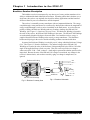
The 2762-17 Intelligent Position Control Module
The 2762-17 Intelligent Position Control Module is a two channel, non-servo positioning
controller for Allen-Bradley 1771 I/O systems. Each channel has four DC outputs for motor
speed and direction control and utilizes a brushless resolver based transducer for absolute
multiturn position feedback. Examples in this manual show the 2762-17 controlling only one
channel. This is for clarity only. The 2762-17 is a true two channel controller that can drive
both channels simultaneously.
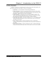
Module configuration is accomplished
from the processor or integral keyboard and
display. Module configuration includes
transducer setup, which sets the relationship
of transducer position to load position, and
positioning setup, which sets the loads' target
position and the motor control parameters
needed to reach the target position once a
Move Profile is initiated.
2762-17
LEAD
SCREW
LOAD
TRANSDUCER
MOTOR
Once configured, the 2762-17 waits for a
move profile command. Once the command
is given from the processor or keyboard, the
module uses the transducer position to fire its
motor control outputs at the appropriate
positions. The 2762-17 turns the motor off at
a programmed stop position and the load
coasts to the target position.
If the load does not stop at the target
position, the 2762-17 adjusts the stop position
and runs the move profile again. Because
inertia and friction in most systems is
repeatable, the module can accurately
position the load without servo feedback.
The 2762-17 also gives you the ability to
jog the position from the processor, keyboard
or external input.
Figure 1.1 Typical 2762-17 Application
The 2762-17 uses block transfer writes to program the module from the processor. It uses
block transfer reads to transmit position and tachometer information or programming data back to
the processor. The module uses single transfer writes to initiate move profiles or jog the load
position from data in the output data table. It uses single transfer reads to transmit positioning
status to the input data table. The 2762-17 can perform concurrent block and single transfers.
ADVANCED MICRO CONTROLS INC.
5
Chapter 1 Introduction to the 2762-17
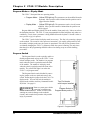
Brushless Resolver Description
The brushless resolver is unsurpassed by any other type of rotary position transducer in its
ability to withstand the harsh industrial environment. An analog sensor that is absolute over a
single turn, the resolver was originally developed for military applications and has benefited
from more than 50 years of continuous use and development.
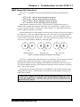
The resolver is essentially a rotary transformer with one important distinction. The energy
coupled through a rotary transformer is not affected by shaft position whereas the magnitude of
energy coupled through a resolver varies sinusoidally as the shaft rotates. A resolver has one
primary winding, the Reference Winding and two secondary windings, the SIN and COS
Windings. (See Figure 1.2, Resolver Cut Away View). The Reference Winding is located in
the rotor of the resolver, the SIN and COS Windings in the stator. The SIN and COS Windings
are mechanically displaced 90 degrees from each other. In a brushless resolver, energy is
supplied from the Reference Winding to the rotor by a rotary transformer. This eliminates
brushes and slip rings in the resolver and the reliability problems associated with them.
In general, the Reference Winding is excited by an AC voltage called the Reference Voltage
(VR). (See Figure 1.3, Resolver Schematic). The induced voltages in the SIN and COS
Windings are equal to the value of the Reference Voltage multiplied by the SIN or COS of the
angle of the input shaft from a fixed zero point. Thus, the resolver provides two voltages
whose ratio (SIN / COS = TAN , where = shaft angle) represents the absolute position of the
input shaft. Because the ratio of the SIN and COS voltages is considered, any changes in the
resolvers’ characteristics, such as those caused by aging or a change in temperature, are
ignored.
R efe ren ce W in d in g
1 Red
CO
Winding
C
R
3
R1 Red Wht
l
IN
Winding
R
R2
CO θ
l Wht
Rotary
Transformer
Wire Color
2
θ
R
4
el
INθ
lu
S IN a nd C O S W ind ing s
Fig 1.2 Resolver Cut away View
6
Fig 1.3 Resolver Schematic
ADVANCED MICRO CONTROLS INC.
Chapter 1 Introduction to the 2762-17
AMCI Compatible Transducers
The 2762-17 is compatible with the following NEMA 4 transducers manufactured by
AMCI.
! HTT-20-100: 100 turn absolute position transducer
! HTT-20-180: 180 turn absolute position transducer
! HTT-20-1000: 1,000 turn absolute position transducer
! HTT-20-1800: 1,800 turn absolute position transducer
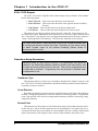
Each transducer contains two resolvers. The first resolver, called the fine resolver, is
attached with a flexible coupler directly to the shaft. The second resolver, called the coarse
resolver, is geared to the fine. This gear ratio, either 99:100 or 179:180 determines the total
number of turns the transducer can encode.
At the mechanical zero of the transducer the electrical zeros of the two resolvers are aligned.
See Figure 1.4A. After one complete rotation, the zero of the coarse resolver lags behind the
zero of the fine by one tooth, either 1/100 or 1/180 of a turn. After two rotations the lag is
2/100 or 2/180. See Figures 1.4B and 1.4C. After 100 or 180 turns, the electrical zeros of the
resolvers are realigned and the multiturn cycle begins again.
FINE
COURSE
0
0
FINE
COURSE
0
0
FINE
COURSE
0
0
A
B
C
Mechanical Zero
After One Turn
After Two Turns
Figure 1.4 Resolver Alignment in Multiturn Transducers
The 2762-17 simultaneously reads the resolvers every 800 µSec. The fine resolver yields the
absolute position within the turn directly. Using a proprietary algorithm, the 2762-17
determines the number of turns completed by the difference in positions of the two resolvers.
The absolute multiturn position is then calculated as ((number of turns completed * counts per
turn) + fine resolver position).
The 1,000 and 1,800 turn transducers have an additional 10:1 gear ratio between the input
shaft and the fine resolver. Therefore they can encode ten times the number of turns but at a
tenth of the resolution.
To the 2762-17 module, the 1,000 and 1,800 turn transducers appear to be 100
or 180 turn transducers. Therefore only 100 and 180 turn transducers are
discussed in this manual.
ADVANCED MICRO CONTROLS INC.
7
Chapter 1 Introduction to the 2762-17
2762-17 DC Outputs
The 2762-17 has a total of eight DC motor control outputs, four per channel. Each channel
has the following outputs.
Motor Forward - Turns on to rotate the motor in one direction.
Motor Reverse - Turns on to rotate the motor in the opposite direction of Motor
Forward.
! High Speed - Turns on when motor can be driven at high speed.
! Low Speed - Turns on when the motor should be driven at low speed.
The outputs are sourcing type and are rated at 40 volts, 2 amps DC. Surge rating is 4 Adc
for 10 mSec per output. Each channel (four outputs) has its own power supply connections and
fuse. Fused with a 7 amp fast blow fuse, the suggested maximum output current per channel is
5 amps. Each output has a LED indicator. Two blown fuse indicators are also present.
!
!
The output names Motor Forward and Motor Reverse are completely arbitary and
do not imply the direction of travel of the load. Depending on your setup, turning
the Motor Forward output on will produce increasing position counts or
decreasing position counts.
Transducer Setup Parameters
Transducer setup for each channel consists of nine parameters that define the
transducer, the relationship between transducer position and load position, and
the upper and lower position limits for the load. They can be programmed from
the keyboard or processor. Programming from the processor is disabled when
the keyboard is in use.
Transducer Type
This parameter must be set to the type of transducer attached to the channel, 100 turn or 180
turn. The 2762-17 needs this information to decode the multiturn position from the difference
in positions of the two resolvers.
Count Direction
By default, the transducer position increases with CW rotation of the shaft, when looking at
the shaft. Changing this parameter reverses the rotation for increasing position. In application
terms, if the position of the load is increasing and the transducer position is decreasing, simply
change this parameter.
Decimal Point
This parameter sets the position of a decimal point on many of the modules' displays and is
for the user only. It does not affect the data sent over the backplane. For example, your travel
is measured in inches and your resolution is one thousandth of an inch. Setting a decimal point
at three forces many of the displays to show 'nnn.nnn' where nnnnnn is the present value.
8
ADVANCED MICRO CONTROLS INC.
Chapter 1 Introduction to the 2762-17
Transducer Setup Parameters (continued)
Number of Turns
Use this parameter, along with the Scale Factor parameter, to set the correlation between
the transducer position and the load position. This parameter is usually set to the number of
rotations the transducer makes for the expected linear travel of the load. Its minimum value is
0.1 turns. Its maximum value is equal to the number of turns of the transducer, 100 or 180
turns, with 0.1 turn resolution. When using it with a 1000 or 1800 turn transducers consider it
programmable from 1 turn to 1000 or 1800 turns with 1.0 turn resolution.
Scale Factor
Use this parameter, along with the Number of Turns parameter, to set the correlation
between the transducer position and the load position. The Scale Factor sets the position
resolution and must be set to the number of counts needed over the programmed Number of
Turns parameter. The range of values that can be programmed for the Scale Factor is 2 to
(4096 * Number of Turns).
Counts per Turn and Full Scale Count
The Scale Factor divided by the Number of Turns is the number of counts per turn. The
2762-17 uses this ratio when calculating the position values. Therefore the actual values for
Number of Turns and Scale Factor can be any convenient numbers. For example, assume
150.7641 turns corresponds to 9.000 inches of travel. Therefore, the counts per turn ratio is
9000 / 150.7641 ! 59.6958. Setting the Number of Turns to 150.8 results in a significant error,
9000 / 150.8 ! 59.7213. Using successive approximation techniques to arrive at different
values, setting the Number of Turns to 138.1 and the Scale Factor to 8244 results in a much
better approximation. {8244 / 138.1 ! 59.6958. Its accuracy to the actual ratio is greater than
five decimal places}.
The 2762-17 uses the counts per turn
ratio to calculate the Full Scale Count
(FSC). The Full Scale Count is the largest
number the position value will attain
before the transducer completes its multiturn cycle. (100 or 180 turns.) See Figure
1.5.
The Full Scale Count sets limits on the
values that can be programmed into the
other transducer setup parameters as well
as some of the positioning setup
parameters.
Full Scale
Travel
32 inches
180 Turns
2.000 in
Expected
1.250 in
Travel
LOAD
20 inches
112.5 Turns
20,000 Counts
Full Scale
Count
((20,000/112.5) * 180) - 1
= 31,999
Counts range from
0 to 31,999
Figure 1.5 Full Scale Count Example
ADVANCED MICRO CONTROLS INC.
9
Chapter 1 Introduction to the 2762-17
Transducer Setup Parameters (continued)
Linear Offset
The Linear Offset is a fixed number that is added to the transducer position data. It adjusts
the range of position values the 2762-17 uses. For example, a twenty inch expected travel is
over a range of 35.000 to 55.000 inches. Programming a linear offset of 35,000 will force the
position data to read from 35,000 to 55,000. The module can output positions between -99,999
and 999,999. Therefore the range of values for the linear offset is -99,999 to (999,999 - Full
Scale Count).
Preset Value
The Preset Value allows you to adjust the position data without rotating the transducer shaft.
It's most commonly used to set the position data equal to the actual position of the load. Once
programmed, the position can be set to the preset value from the keyboard or processor. The
programmable range of the Preset Value is Linear Offset to (Linear Offset + FSC).
Upper and Lower Travel Limits
In many applications, the machine will be damaged if the load exceeds the boundaries of
expected travel. The Upper and Lower Travel Limits are programmable boundaries that will
disable the motor outputs if the position exceeds them during a move profile. Once the position
exceeds these limits, the only way to move the load is by jogging the position. The upper travel
limit sets the upper boundary and is programmable from (Lower Travel Limit + 1) to (Linear
Offset + Full Scale Count). The lower travel limit sets the lower boundary and is
programmable from Linear Offset to (Upper Travel Limit -1).
Positioning Setup Parameters
Positioning setup for each channel consists of six parameters that define the positions at
which the motor control outputs change state. They can be programmed from the
keyboard or processor. Processor programming is disabled when the keyboard is in use.
Target Position
Target Position is the desired position of the load when a move profile is completed. It is
programmed as an absolute position within the Lower and Upper Travel Limits. Except for
Positioning Direction, the other parameters are programmed as absolute values relative to this
position.
The direction of approach to the Target Position is programmable. Therefore, the
definitions of the parameters refer to a positive side of the Target Position and a negative side
of the Target Position. The positive side refers to all values greater than the Target Position
and the negative side refer to all values less than the Target Position.
Positioning Direction
Positioning Direction defines the direction of the approach to the Target Position. A
Positive Approach forces an approach from the positive side of the Target Position. A Negative
Approach forces an approach from the negative side. If the starting position of the move
profile is on the opposite side of the Target Position, the 2762-17 will drive the load to the
correct side of the Target Position before completing the move profile.
10
ADVANCED MICRO CONTROLS INC.
Chapter 1 Introduction to the 2762-17
Positioning Setup Parameters (continued)
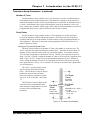
Overshoot Offset
The Overshoot Offset can be programmed to
any value between (Low Speed Offset +1) and
Full Scale Count.
Overshoot Offset
Target
Overshoot
1.599 in
Overshoot Offset
The 2762-17 uses the Overshoot Offset to
determine how far away from the Target Position
to drive the load before beginning the approach to
the Target Position. If the starting position is
between the Target Position and Overshoot
Offset, or on the opposite side of the Target
Position, the 2762-17 will drive the load to the
Overshoot Offset before beginning the approach.
The Overshoot Offset is also used when backing
off from the Target Position if the previous
attempt to reach it failed.
1.599 in
Overshoot
Target
Positive Approach
Negative Approach
If a positive approach is defined and (Target
Figure 1.6 Overshoot Offset
Position + Overshoot Offset) is greater than the
Upper Travel Limit, the module will issue an 'Invalid Profile' error message when a move
profile is initiated. The same error message will be issued if a negative approach is defined and
(Target Position - Overshoot Offset) is less than the Lower Travel Limit.
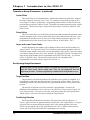
Low Speed Offset
Overshoot Low Speed
The Low Speed Offset defines the
position that the motor switches from high
to low speed. It is used in two ways.
Target
Low Speed
Offset
Low Speed
Offset
Low Speed
Offset
Overshoot Low Speed
ADVANCED MICRO CONTROLS INC.
Low Speed
Offset
When approaching the Target
Overshoot
.997 in
Position from the correct direction,
(Target Position ± Low Speed
.997 in
Offset) is the point at which the
Low Speed
Low Speed
.997 in
motor switches from high to low
speed.
.997 in
! When traveling towards the OverOvershoot
shoot, the motor will switch to low
speed when the position is
Target
(Overshoot ± Low Speed Offset). It
Positive Approach
Negative Approach
will then travel at low speed to the
Overshoot position, turn off the
Figure 1.7 Low Speed Offset
motor, and reverse direction before
completing the profile.
The Low Speed Offset can be programmed to zero or from (Stop Offset + 1) to (Overshoot
Offset - 1). Setting the Low Speed Offset to zero disables the high speed motor output. All
movement will be at low speed if the Low Speed Offset equals zero.
!
11
Chapter 1 Introduction to the 2762-17
Positioning Setup Parameters (continued)
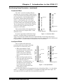
Stop Offset
Once on the correct side of the Target Position,
the Stop Offset defines the position at which the
motor outputs are turned off at the end of the move
profile. The load then coasts to the Target
Position.
The Stop Offset can be programmed to any
value between one and (Low Speed Offset - 1). If
the Low Speed Offset equals zero, the Stop Offset
can be programmed to any value between one and
(Overshoot Offset -1).
Target
Overshoot
Stop
.601 in
Offset
Stop
Low Speed
Low Speed
Stop
Overshoot
Stopin
.601
Offset
If the load is not at Target Position at the end of
Target
the move profile the 2762-17 adjusts the Stop
Positive Approach
Negative Approach
Offset by the difference between the actual
position and the Target Position. The module will
Figure 1.8 Stop Offset
then back out to the overshoot position and run the
profile again with the adjusted Stop Offset. The
2762-17 will not allow the adjusted value of the
Stop Offset to be greater than the Overshoot
Offset.
When initiated from the keyboard, the 2762-17 will adjust and re-run the profile a maximum
of three times before issuing an error message. When initiated from the backplane, the module
will adjust and re-run the profile the number of times specified by the Retry Value parameter
before issuing an error message. If the Target Position is reached, the 2762-17 stores the
adjusted Stop Offset if it is within the range listed above.
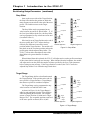
Target Range
The Target Range defines a dead band around
the Target Position. If the position at the end of a
move profile is (Target Position ± Target Range)
then the move profile is considered complete.
Overshoot
Target
Low Speed
The Target Range can be programmed to any
value between zero and Full Scale Count.
.200 in
± Target
Range
Stop
Stop
As shown in Figure 1.9, the Target Range is
added to and subtracted from the Target Position
when determining the dead band. For example,
assume a Target Position of 10,000 and a Target
Range of five. The acceptable positions at the end
of the move profile are then 9,995 to 10,005.
Low Speed
Target
.200 in
Overshoot
± Target
Range
Positive Approach
Negative Approach
Figure 1.9 Target Range
12
ADVANCED MICRO CONTROLS INC.
Chapter 1 Introduction to the 2762-17
Positioning Setup Parameters (continued)
Retry Value
The Retry Value is only used when a move profile is initiated from the backplane and
specifies the maximum number of attempts the 2762-17 will make to reach the target
position if the first attempt failed.
The Retry Value can be programmed to any value between 1 and 255. The default value is
three. If you program a value greater than 255 or a value of zero, the module responds with
and error message. The Retry Value is programmable from the backplane only. There is no
front panel display for this parameter. You must use a Read Positioning Setup Auxiliary
Command (See Pg. 19) to check its value.
ADVANCED MICRO CONTROLS INC.
13
Chapter 1 Introduction to the 2762-17
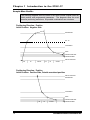
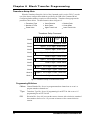
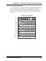
Sample Move Profiles
The following diagrams show the state of the motor control outputs based on
initial position and programmed parameters. The diagrams show the most
common positioning waveforms. All possible combinations are not shown.
Positioning Direction: Positive
Initial Position: Negative Side
OVERSHOOT
OS - LS
LOW SPEED
STOP
TARGET POSITION
.200 in
TARGET RANGE
INITIAL POSITION
HS
LS
COAST
HS
LS
COAST
Positioning Direction: Positive
Initial Position: Positive Side, Outside overshoot position
INITIAL POSITION
OVERSHOOT
LOW SPEED
STOP
TARGET POSITION
HS
14
LS
COAST
.200 in
TARGET RANGE
ADVANCED MICRO CONTROLS INC.
Chapter 1 Introduction to the 2762-17
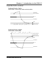
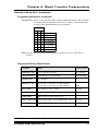
Sample Move Profiles (continued)
Positioning Direction: Positive
Initial Position: Positive Side, Inside overshoot position
OVERSHOOT
INITIAL POSITION
OS - LS
LOW SPEED
STOP
TARGET POSITION
LS
COAST
HS
LS
COAST
.200 in
TARGET RANGE
Positioning Direction: Negative
Initial Position: Positive Side
HS
LS
COAST
HS
LS
COAST
INITIAL POSITION
.200 in
TARGET RANGE
TARGET POSITION
STOP
LOW SPEED
OS - LS
OVERSHOOT
ADVANCED MICRO CONTROLS INC.
15
Chapter 1 Introduction to the 2762-17
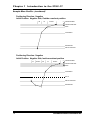
Sample Move Profiles (continued)
Positioning Direction: Negative
Initial Position: Negative Side, Outside overshoot position
HS
LS
COAST
.200 in
TARGET RANGE
TARGET POSITION
STOP
LOW SPEED
OVERSHOOT
INITIAL POSITION
Positioning Direction: Negative
Initial Position: Negative Side, Inside overshoot position
LS
COAST
HS
LS
COAST
.200 in
TARGET RANGE
TARGET POSITION
STOP
LOW SPEED
OS-LS
INITIAL POSITION
OVERSHOOT
16
ADVANCED MICRO CONTROLS INC.
Chapter 1 Introduction to the 2762-17
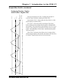
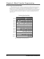
Sample Move Profiles (continued)
INITIAL POSITION
TARGET RANGE
TARGET POSITION
STOP
LOW SPEED
OS - LS
OVERSHOOT
Positioning Direction: Positive
Initial Position: Negative Side
This waveform shows the 2762-17 making four attempts to
reach the Target Position by adjusting the Stop Offset.
The 2762-17 will run the profile a maximum of four times
before issuing an error message when the profile is initiated from
the keyboard. When initiated from the backplane, the 2762-17 uses
the Retry Value parameter to determine how many times to run the
profile. The default Retry Value is three, which means the profile
will run four times.
If the 2762-17 adjusts the Stop Offset to the Overshoot Offset
and the Target Position is still overshot, the module will stop trying
to reach the Target Position and issue an error message.
HS
LS
OFF
HS
LS
OFF
LS
OFF
LS
OFF
LS
OFF
LS
OFF
LS
OFF
LS
OFF
Note that the 2762-17 will not adjust the Stop Offset to a value
greater than the Overshoot Offset.
ADVANCED MICRO CONTROLS INC.
17
Chapter 1 Introduction to the 2762-17
Jogging the Load Position
The 2762-17 allows you to manually jog the load position in one of three ways. From the
processor, the modules' keypad, or an external input. The motor runs at low speed when
jogging the position.
! C A U T IO N
It is possible to jog the load past the upper or lower travel limits.
Jogging from the Processor
You jog the position from the processor by setting a bit in the output image table. Jog Up
and Jog Down bits are defined for each channel. The position will jog as long as the bit is set.
Jogging from the Keyboard
The 2762-17 has a separate menu for jogging the position. The module displays the current
position when in this menu. Press the [▲] or [▼] key to jog the position in the corresponding
direction. The position will jog as long as the key is pressed.
Jogging from the external input
The 2762-17 accepts a single input to jog the position. Bits in the output image table enable
the input and set the jogs' direction. Each channel has its own enable and direction bits.
! C A U T IO N
It is possible to jog both channels simultaneously with the external input.
It is also possible to simultaneously jog the channels in opposite
directions.
The external input is opto-isolated and has the following electrical specifications.
!
!
18
Input Voltage: 10 to 24 Volts AC or DC.
Input Current: 10 mA required to turn input on.
ADVANCED MICRO CONTROLS INC.
Chapter 1 Introduction to the 2762-17
Auxiliary Commands
Auxiliary Commands are commands issued from the processor with a block transfer write.
They affect the operation of the module. There are six commands:
!
!
!
!
!
!
Clear Errors - Clears all transducer faults and programming errors.
Disable Keyboard - Disables all programming from the keyboard. Move profiles
cannot be initiated. Parameters can be monitored from the keyboard but they cannot
be modified. Jogging from the keyboard is still enabled.
Enable Keyboard - Counteracts a previous Disable Keyboard Command. The
status of the keyboard is retained when power is removed. The only way to enable
the keyboard after a Disable Keyboard command is with this command.
Read Status and Position - After this command, the 2762-17 will transmit module
status with position and tachometer data for both transducers when a block transfer
read addresses the module.
Read Transducer Setup - After this command, the 2762-17 will transmit
Transducer Setup data for the specified channel when a block transfer read addresses
the module.
Read Positioning Setup - After this command, the 2762-17 transmits Positioning
Setup data for the specified channel when a block transfer read accesses the module.
ADVANCED MICRO CONTROLS INC.
19
Chapter 1 Introduction to the 2762-17
Notes
20
ADVANCED MICRO CONTROLS INC.
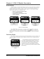
Chapter 2 2762-17 Module Description
This chapter describes the physical layout of the 2762-17 module as well as
keyboard programming.
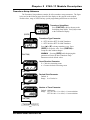
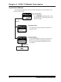
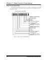
Front Panel Description
Program Switch - (On other side of PC
Board, hidden from view.) Used to
enable programming the 2762-17 from
the keyboard. A two pin header next to
the switch can be removed to disable
Program Mode. The switch can also be
disabled from the processor.
Function Display - Used to display position
data and parameter values. The eight
LED indicators designate what is showing
on the display. When programming a
parameter, a blinking digit in the display
shows the position of the Cursor.
Status Indicators - Indicates the operating
status of the module.
PRG - Yellow light is on when the module is
in Program Mode.
RUN - Green light is blinking when the
module is operating.
FAULT - Red light is on when there is a
module fault. The type of fault is
shown on the display.
Keyboard - Used to examine or change the
programming of the module. Also used
to start a move profile or jog the position.
Transducer Input Connector - Connector
for the two AMCI transducers.
Motor Control Output Connector Connector for the eight DC motor control
outputs and the external jog input.
Figure 2.1 2762-17 Front Panel
ADVANCED MICRO CONTROLS INC.
21
Chapter 2 2762-17 Module Description
Program Mode vs. Display Mode
The 2762-17 front panel has two operating modes.
Program Mode - (Yellow PRG light on) The parameters can be modified from the
keyboard. Move profiles can be initiated and the position can be
jogged from the module.
! Display Mode - (Yellow PRG light off) The parameters can be viewed, but not
modified. Move profiles cannot be initiated but the position can
still be jogged.
Program Mode and Display Mode refer to the modules' front panel only. It does not refer to
the backplane interface. The 2762-17 is not programmable from the backplane only under two
conditions. First is when a parameter is being modified from the keyboard. Second is when a
move profile or jog is in process.
!
The 2762-17 can be locked in display mode in two ways. The first is by removing a jumper
on the module. The second is with a processor instruction. It is usually good practice to lock
the module in display mode once the system is operational. This will prevent someone from
accidentally changing the 2762-17's parameters while the system is running. The only times
that changes to the programming should be allowed are during set-up or trouble shooting
procedures.
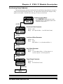
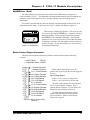
Program Switch
The Program Switch is used to quickly enable or
disable program mode as long as the 2762-17 is not
locked in display mode. The module is in program
mode when the switch is pushed towards the back
of the module. The module is in display mode
when the switch is pushed towards the front of the
module. The yellow PRG light is on when the
2762-17 is in program mode.
The Program Switch can be disabled by removing the jumper on the two pin header next to the
switch. Removing this jumper locks the 2762-17 in
display mode. You can also lock the module in
display mode with the Auxiliary Command Disable
Keyboard. See page 18.
Remove system power before
removing or installing any
module in an I/O chassis. Failure to observe this
warning can result in damage to the module's
circuitry and/or undesired operation with possible
injury to personnel.
! W A R N IN G
Two Pin Header
with Jumper Installed.
Program Switch in
Program Mode position.
Figure 2.2 Program Switch
22
ADVANCED MICRO CONTROLS INC.
Chapter 2 2762-17 Module Description
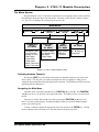
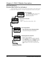
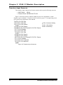
The Menu System
Programming the 2762-17 from the front panel involves navigating a menu system in which
the parameters are broken down into sub-menus. The menu system layout is shown in Figure
2.3. The 2762-17 displays the current position on power up.
MAIN MENU
POSITION
TAC
TRANSDUCER
SETUP
POSITIONIN
SETUP
TRANSDUCER
SETUP
SU MENU
POSITIONIN
SETUP
SU MENU
RUN
PROFILE
SU MENU
Transducer Type
Count Direction
Number of Turns
Scale Factor
Linear Offset
Preset Value
Upper Travel Limit
Lower Travel Limit
Overshoot Offset
Low Speed Offset
Stop Offset
Target Range
Target Position
Positioning
Direction
RUN
PROFILE
JO
JO
SU MENU
Displays Position.
s , t Keys og
the position.
Figure 2.3 2762-17 Menu System Layout
Switching between Channels
Pressing the [NEXT] key will switch between the two channels at almost every point in the
menu system. The only time you cannot switch between the two channels is when you are
setting the Positioning Direction in the Run Profile submenu. The 'D' indicator LED is on when
displaying data for channel two.
Navigating the Main Menu
The main menu is navigated with three keys, [FUNCTION], [!] , and ["]. The [FUNCTION]
and [!] keys move you one item to the right in the menu. The ["] key moves you one item to
the left.
The menu is circular. When at the Jog menu, pressing the [FUNCTION] or [!] keys will
move you to the position display. Pressing the ["] key when you are at the Position display
returns you to the Jog item.
To enter a submenu, display the appropriate menu item and press the [ENTER] key. Exiting
the last submenu item will return you to the main menu at the point you left it.
ADVANCED MICRO CONTROLS INC.
23
Chapter 2 2762-17 Module Description
The Menu System (continued)
Navigating the Submenus in Display Mode
Once in a submenu, use the [FUNCTION] key to scroll through the parameters. Pressing the
[FUNCTION] key when at the last parameter returns you to the main menu. Press the [ENTER]
key to re-enter the submenu.
You cannot program parameters or initiate a move profile while in display mode. You can
jog the position. The jog submenu displays the current position. Press the [▲] or [▼] keys to
increase or decrease the current position. The position will jog as long as a key is pressed. Use
the [FUNCTION] key to exit the submenu.
Navigating the Submenus in Program Mode
You program most of the parameters in the Transducer Setup and Positioning Setup
submenus. One of the digits will blink when you first enter a parameter display. This shows
the position of the cursor. Use the [!] , and ["] keys to move the cursor and the [▲] and [▼]
keys to change the value of the digit. To quickly set most parameters to zero, press the
[CLEAR] key. Once the parameter is modified, press the [ENTER] key to accept the value. If
the 2762-17 accepts the value the cursor is removed from the display.
The module will only accept valid values for the parameters. If the 2762-17 does not accept
a value it will return the display to the last valid number and move the cursor to the first digit.
The valid range for many parameters is based on the values of other parameters. If the module
does not accept a new value, check the other parameter settings.
Pressing the [FUNCTION] key at any time will remove the cursor if you do not want to
modify the parameter that is on the display. The [FUNCTION] key is also used to scroll to the
next parameter in the submenu.
The Run Profile submenu allows you to initiate a move profile from the module. Simply
program the Target Position and the Positioning Direction. The move profile is initiated when
you press [ENTER] at the Positioning Direction display. When the move profile is complete the
2762-17 will display the final position with all of the digits blinking if it completes
successfully. If it does not complete, the module displays one of several error messages.
Pressing the [CLEAR] key while a move profile is running will immediately stop the profile.
The Jog submenu behaves as it does in display mode. Press the [▲] or [▼] keys to increase
or decrease the current position. Press the [FUNCTION] key to exit the submenu.
24
ADVANCED MICRO CONTROLS INC.
Chapter 2 2762-17 Module Description
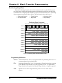
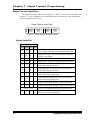
Indicator LED Patterns
The eight LEDs above the seven segment displays are the indicator LEDs. Figure 2.4 is a
list of the menu and submenu items and the associated indicator LED pattern. Note that some
of the parameters have the same indicator pattern. In these cases, the actual displays are
different enough to distinguish between the parameters.
POS TAC SF
O
A
B
C
D
POSITION
TACHOMETER
TRANSDUCER SETUP
Transducer Type
Count Direction
Decimal Point
Number of Turns
TRANSDUCER
SETUP
SUBMENU
Scale Factor
Linear Offset
Preset Value
Upper Travel Limit
Lower Travel Limit
POSITIONING SETUP
OverShoot Offset
POSITIONING
SETUP
SUBMENU
Low Speed Offset
Stop Offset
Target Range
RUN PROFILE
Target Position
RUN
PROFILE
SUBMENU
Positioning Direction
All other RP Displays
JOG
Jog Position
JOG SUBMENU
LED OFF
LED ON
LED OFF For Channel 1
LED ON For Channel 2
Figure 2.4 Indicator LED Patterns
ADVANCED MICRO CONTROLS INC.
25
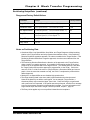
Chapter 2 2762-17 Module Description
Position Display
As shown in figure 2.5a, the Position Display shows the current position when a transducer
is properly attached to the channel. Figures 2.5b and 2.5c show the display when there is a
transducer fault. Figure 2.5b is the channel 1 display. Figure 2.5c is the channel 2 display.
There are four major causes of a transducer fault.
!
!
!
!
Broken or intermittent transducer cable
Non-compatible transducer
Improper wiring of the transducer Cable
Faulty Transducer.
PLC SER IES
Fig A
CURRENT POSITION
PLC SER IES
PLC SER IES
Fig B
TRANSDUCER FAULT
CHANNEL 1
Fig C
TRANSDUCER FAULT
CHANNEL 2
Figure 2.5 Position Displays
The red FAULT LED is lit when there is a transducer fault. If this LED is on while the
position is displayed, the fault is on the other channel. Use the [NEXT] key to switch to the
other channel. The fault can be cleared by pressing the [CLEAR] key if the 'Err1' message is
blinking.
Tachometer Display
The tachometer display shows the current speed of the transducer in counts per minute. See
Figure 2.6. If there is a transducer fault, the display will show the 'Err1' messages instead of
the current speed.
PLC SER IES
The relationship to load speed is application specific.
For example, programming the Number of Turns and
Scale Factor parameter such that the transducer rotates
one count for every 0.001" of load travel means the
tachometer will read out in thousandths of an inch per
minute. This equals inches per minute with three decimal
point accuracy.
Figure 2.6 Tachometer
Display
26
ADVANCED MICRO CONTROLS INC.
Chapter 2 2762-17 Module Description
Transducer Setup Submenu
The Transducer Setup submenu contains all of the transducer setup parameters. The figure
below and on the following page show all of the displays as they appear on the module.
Default values, range of values and any special programming instructions are also listed.
Transducer Setup Menu
PLC SERIES
Press [FUNCTION] or [å] to advance to the
Positioning Setup Menu. Press [ä] to return
to the Tachometer Display.
[ENTER]
Transducer Type Parameter
PLC SERIES
0 = HTT-20-100 or HTT-20-1000 Transducer
1 = HTT-20-180 or HTT-20-1800 Transducer
Press [s] or [t] to change transducer type. Press
[ENTER] to accept the value. Press [FUNCTION] to
accept the value without changes.
[FUNCTION]
WARNIN : Pressing [ENTER] while displaying this
parameter will reset all other Transducer Setup
Parameters to their default values.
Count Direction Parameter
PLC SERIES
P = Clockwise increasing count
n = Counter-clockwise increasing count
[FUNCTION]
Decimal Point Parameter
PLC SERIES
Default: 0
Range: 0 to 5 inclusive.
[FUNCTION]
Number of Turns Parameter
PLC SERIES
Default: 180.0 turns
Range: HTT-20-180: 0.1 to 180.0, 0.1 turn resolution
HTT-20-100: 0.1 to 100.0, 0.1 turn resolution
[FUNCTION]
Continued on Pg 2-8
ADVANCED MICRO CONTROLS INC.
27
Chapter 2 2762-17 Module Description
Transducer Setup Submenu (continued)
Continued from Pg 2-7
Scale Factor Parameter
PLC SERIES
Default: 737,280
Range: 2 to (Number of Turns * 4096)
[FUNCTION]
Linear Offset Parameter
PLC SERIES
Default: 0
Range: -99,999 to (999,999 - Full Scale Count†)
[FUNCTION]
Preset Value Parameter
PLC SERIES
Default: 0 (Linear Offset)
Range: Linear Offset to (Linear Offset + FSC†)
[FUNCTION]
Upper Travel Limit Parameter
PLC SERIES
Default: 737,279 (Linear Offset + FSC†)
Range: (Lower Travel Limit + 1) to (Linear Offset + FSC†)
[FUNCTION]
Lower Travel Limit Parameter
PLC SERIES
Default: 0 (Linear Offset)
Range: Linear Offset to (Upper Travel Limit -1)
[FUNCTION]
Returns to
Transducer Setup
Menu
† FSC: Full Scale Count = (Transducer Type {100 or 180} * (Scale Factor/Number of Turns)) - 1
28
ADVANCED MICRO CONTROLS INC.
Chapter 2 2762-17 Module Description
Positioning Setup Submenu
The Positioning Setup submenu contains all of the positioning setup parameters except for
Target Position and Positioning Direction. The figure below show all of the displays as they
appear on the module. Default values and range of values are also listed.
PLC SERIES
Positioning Setup Menu
Press [FUNCTION] or [å] to advance to the
Run Profile menu. Press [ä] to return to the
Transducer Setup menu.
[ENTER]
Overshoot Offset Parameter
PLC SERIES
Default: 1,000
Range: (Low Speed Offset + 1) to Full Scale Count†
[FUNCTION]
Low Speed Offset Parameter
PLC SERIES
Default: 500
Range: 0 and
(Stop Offset + 1) to (Overshoot Offset - 1)
[FUNCTION]
Stop Offset Parameter
PLC SERIES
Default: 100
Range: 1 to (Overshoot Offset - 1) if Low Speed = 0
1 to (Low Speed - 1) if Low Speed ≠ 0
[FUNCTION]
Target Range Parameter
PLC SERIES
Default: 0
Range: 0 to Full Scale Count†
[FUNCTION]
Returns to
Positioning Setup
Menu
† FSC: Full Scale Count = (Transducer Type {100 or 180} * (Scale Factor/Number of Turns)) - 1
ADVANCED MICRO CONTROLS INC.
29
Chapter 2 2762-17 Module Description
Run Profile Submenu,
Running a Move Profile From the Keyboard
As the name implies, you initiate a move profile from this submenu. Move profiles cannot
be initiated while in display mode. You must be in program mode to initiate a move profile.
PLC SERIES
Run Profile Menu
Press [FUNCTION] or [å] to advance to the
Jog menu. Press [ä] to return to the
Positioning Setup menu.
[ENTER]
Target Position Parameter
PLC SERIES
Default: 0
Range: Linear Offset to Linear Offset + FSC†
[FUNCTION]
Not in Program Mode
PLC SERIES
You cannot initiate a move profile when in display
mode. If you try, the 2762-17 displays this error
instead the Positioning Direction parameter.
Positioning Direction Parameter
PLC SERIES
[ENTER]
Default: Positive Approach
Range: Positive Approach or Negative Approach
Press [FUNCTION] to return to the Run Profile Menu
After setting the approach, press [ENTER] to initiate a
move profile. When the profile is complete, the
display changes to one of the five listed on the next
page.
Continued on Pg 2-11
30
ADVANCED MICRO CONTROLS INC.
Chapter 2 2762-17 Module Description
Run Profile Submenu,
Running a Move Profile From the Keyboard (continued)
Continued
from
Pg 2-10
Target Position Reached
PLC SERIES
The current position flashes on the display if the
move profile completes successfully.
Move Profile Stopped
PLC SERIES
The display changes to 'Stop' if the move profile is
halted. Pressing the [CLEAR] key while the move
profile is running will halt the profile.
At Upper Travel Limit
PLC SERIES
During the move profile, the position exceeded the
programmed upper travel limit. The move profile
stops itself immediately when the position exceed the
upper travel limit.
At Lower Travel Limit
PLC SERIES
During the move profile, the position became less
than the programmed lower travel limit. The move
profile stops itself immediately when the position
becomes less than the lower travel limit.
Profile Error
PLC SERIES
If Positioning Direction = Positive:
(Target Position + Overshoot) > Upper Travel Limit
If Positioning Direction = Negative:
(Target Position - Overshoot) < Lower Travel Limit
Target Position cannot be reached
PLC SERIES
ADVANCED MICRO CONTROLS INC.
The target position could not be reached within the
programmed target range. A maximum of four
attempts are made. The 2762-17 adjusts the Stop
Offset after each attempt. If less than four attempts
are made, the module adjusted the Stop Offset to the
Overshoot Offset, which is its maximum value, and
the Target Position was still overshot.
31
Chapter 2 2762-17 Module Description
Jog Position Submenu
The Jog position submenu has only one display that shows the current position or the
transducer fault message.
Run Profile Menu
PLC SERIES
Press [FUNCTION] or [å] to advance to the
Position Display. Press [ä] to return to the
Run Profile menu.
[ENTER]
Transducer Fault
PLC SERIES
You cannot jog the position while the channel is in
transducer fault.
Current Position
PLC SERIES
Use the [s] and [t] keys to increase or decrease the
position. Use caution when jogging the position.
You can jog the position past the upper or lower
travel limits.
[FUNCTION]
Returns to
Jog
Menu
32
ADVANCED MICRO CONTROLS INC.
Chapter 2 2762-17 Module Description
NvRAM Error (Err2)
All of the parameters are stored in a non-volatile static RAM memory when power is
removed from the 2762-17. The NvRAM has an integral lithium battery that will maintain the
parameter values in the absence of power for approximately ten years from the date of
manufacture.
It is remotely possible that the values can become corrupted through electrical noise or an
inopportune power outage. If this occurs, the 2762-17 display will change to figure 2.7.
PLC SER IES
Figure 2.7 NvRAM Error
This message is displayed at all times. This error can only
be cleared by pressing the [CLEAR] key. It cannot be cleared
from the backplane. If the message remains after pressing
the [CLEAR] key, the NvRAM is damaged. If the message
appears on every power up but can be cleared then the battery
is discharged. In either case, the module must be returned to
AMCI for repairs. See the inside front cover, Returns Policy,
for additional information.
Motor Control Output Connector
The motor control output connector has fourteen contacts and accepts the following
connector
!
!
14
13
12
11
10
9
8
7
6
5
4
3
2
1
AMCI Part #:
MS-141
Weidmüller Part #: 128291
+ External Jog Input
– External Jog Input
VIN 1 / Fuse Indicator
CH 1 Motor Forward
CH 1 Motor Reverse
CH 1 High Speed
CH 1 Low Speed
VIN 1 Common
VIN 2 / Fuse Indicator
CH 2 Motor Forward
CH 2 Motor Reverse
CH 2 High Speed
CH 2 Low Speed
VIN 2 Common
Figure 2.8 Motor Control Output
Connector
ADVANCED MICRO CONTROLS INC.
When enabled from the processor, the
position will jog as long as the external jog input
is active.
Input Voltage Specs:
Logic 0: 0 to 3 Vac/dc @ 500 µA max.
Logic 1: 10 to 24 Vac/dc @ 10 mA min.
All motor control outputs are fuse protected.
Fuse 1 protects channel 1 outputs. Fuse 2
protects channel 2 outputs. If a fuse blows, the
appropriate Fuse Indicator will turn on.
A wiring diagram for the motor control
output connector and external jog input are
given in Chapter 3, Motor Control Output
Connections, page 42.
33
Chapter 2 2762-17 Module Description
Transducer Input Connector
The transducer input connector has fourteen contacts and accepts the following connector
!
!
AMCI Part #:
MS-14
Phoenix Part #: MSTB2.5/14-ST-5.08
Figure 2.9 shows the pinout to industry standard resolver wire designations. A cable
diagram is given in chapter 3, Transducer Cable Installation, page 39. An engineering print is
given at the back of the manual. Print # B1091.
14
13
12
11
10
9
8
7
6
5
4
3
2
1
S4, CH2 Fine
S1, CH2 Fine
S4, CH2 Course
S3, CH2 Course
S2, S3, CH2 Fine and S1, S2 CH 2 Course
CH 2 Shields
S4, CH1 Fine
S1, CH1 Fine
S4, CH1 Course
S3, CH1 Course
S2, S3, CH1 Fine and S1, S2 CH 1 Course
CH 1 Shields
R2, CH 1 and CH2
R1, CH1 and CH2
! R1/R2
- Reference Winding
- COS winding
! S2/S4 - SIN Winding
! S1/S3
Figure 2.9 Transducer Input Connector
34
ADVANCED MICRO CONTROLS INC.
Chapter 2 2762-17 Module Description
Fuse Replacement
There are three fuses on the 2762-17. The Power Fuse is located at the top of the module.
The two Output Fuses are located inside the module.
Power Fuse
If the Power Fuse fails, it can be easily replaced. The factory installed fuse is a 3.5 Amp
fast blow, Littelfuse Inc. part number 22503.5. Fuse kits are available from AMCI. The AMCI
part number is SKF-3. Each fuse kit contains five fuses.
Power Fuse
3.5A Fast Blow
To insure continued and adequate
protection, any replacement fuse must have
a rating of 3.5 Amp Fast Blow. Using a higher ampere rating or
slow blow fuses may not protect the module if the fault
conditions are again applied.
! C A U T IO N
Remove system power before removing or
installing any module in the I/O Chassis.
Failure to observe this warning can result in damage to the
module's circuitry and/or undesired operation with possible
injury to personal.
! W A R N IN G
Figure 2.10 Power Fuse
ADVANCED MICRO CONTROLS INC.
35
Chapter 2 2762-17 Module Description
Fuse Replacement (continued)
Output Fuses
If an Output Fuse fails, the module must be opened before the fuse can be replaced. The
factory installed fuses are 7A fast blow, Littelfuse Inc. part # 225007. A fuse kit of five fuses is
available from AMCI. The AMCI part number for the kit is SKF-4.
! C A U T IO N
To insure continued and adequate protection, any replacement fuse must
have a rating of 7 Amp Fast Blow. Using a higher ampere rating or slow
blow fuses may not protect the module if the fault conditions are again
applied.
! C A U T IO N
Output fuse replacement should be done in an ESD safe environment
because the module must be opened to replace the output fuses.
! W A R N IN G
Remove system power before removing or installing any module in the
I/O Chassis. Failure to observe this warning can result in damage to the
module's circuitry and/or undesired operation with possible injury to
personal.
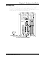
Refer to figure 2.11 when replacing the fuses.
1) Remove the module from the I/O chassis and lay it on an ESD mat so that it is
orientated as it is in the picture.
2) Remove the six screws that have boxes around them and arrows pointing to them.
3) Gently open the module like a book, with the bottom of the panel going to the left.
4) Replace the fuse. Channel 1 fuse is closest to pin 14 of the connector. Channel 2
fuse is closest to pin 6.
5) Reposition the side panel onto the unit making sure the ribbon cable is not pinched
between the panel and the rest of the module. Replace the screws.
CHANNEL 1
FUSE
CHANNEL 2
FUSE
Figure 2.11 Output Fuse Placement
36
ADVANCED MICRO CONTROLS INC.
Chapter 3 Hardware Installation
This chapter describes how to install the 2762-17 into the I/O chassis as well as
the HTT-20 transducers and cable. Suggested wiring of the motor control
outputs and external jog input is also included.
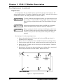
Power Requirements
The 2762-17 draws it power from the I/O chassis + 5Vdc supply. The maximum current
draw is 800 mA. Add this to the power requirements of all other modules in the chassis when
determining maximum system load to avoid exceeding backplane or power supply capacity.
Installing the Module
! W A R N IN G
Remove system power before removing or installing any module in an
I/O chassis. Failure to observe this warning may result in damage to the
module's circuitry and/or undesired operation with possible injury to
personal.
Fig 3.1 Module Installation
Install the module in a single
slot pair within the chassis. A
slot pair is two adjacent
backplane slots, the left of
which is even numbered. Most
A-B chassis have the slots
numbered on the backplane
silkscreen. Figure 3.1 shows
two modules. The module on
the left is installed correctly in
a single slot pair while the
module on the right is
incorrectly installed in two slot
pairs.
The 2762-17 must be installed in a single slot pair to operate properly.
Keying Bands
Plastic keying bands can be inserted into the top backplane connector to prevent the
insertion of other modules. Insert the bands between the following pins:
!
!
Pins 28 and 30
Pins 32 and 34.
ADVANCED MICRO CONTROLS INC.
37
Chapter 3 Hardware Installation
Transducer Mounting
All AMCI HTT-20 resolver based transducers are designed to operate in the industrial
environment and therefore require little attention. However, there are some general guidelines
that should be observed to ensure long life.
!
!
Limit transducer shaft loading to the following maximums:
Radial Loads
Axial Loads
100 lbs. (445 N)
50 lbs. (222.5 N)
Minimize shaft misalignment when direct coupling shafts. Even small
misalignments produce large loading effects on front bearings. It is
recommended that you use a flexible coupler whenever possible.
HTT-20-(x) Transducer Outline Drawing
3.000 (76.2)
2.000 (50.8)
1.000
(25.4)
0.500 (12.7)
4.00 (101.6)
0.375 (9.53)
0.500 (12.7)
0.150 (3.81)
(25.4)
1.000
2.000 (50.8)
4.375 (111.1)
1.25 (31.8)
0.6247 (15.87)
0.6237 (15.84)
1.1811 (30.00)
Diameter
1.1815 (30.01)
1.1807 (29.99)
See Keyway
Specifications
1/4 - 20 UNC-2B
0.500 (12.7) Deep
4 Places
0.900 (22.9) Max.
Total Clearance of 5.5 (140) needed
for removal of mating connector.
MS3102E20-27P Connector.
Mates with MS3106A20-27S
1.175
(29.8)
Keyway Specifications
.1885(4.79)
.1895(4.81)
.106(2.69)
DEEP
.108(2.74)
1.0(25.4)
Key
30 ± 5
.187(4.75)
S .
.188(4.78)
1.0(25.4)
0.085
.086
in ± 0.020
(2.16 ± 0.51)
Fig 3.2 HTT-20-(x) Outline Drawing
38
ADVANCED MICRO CONTROLS INC.
Chapter 3 Hardware Installation
Transducer Cable Installation
The transducer cable used with the 2762-17 module must be BELDEN 9731 or an exact
equivalent. Complete cables can be ordered from AMCI with the part number C2TT-(x) where
(x) is the length in feet. A wiring diagram of the C2TT-(x) cable is on the next page, figure 3.4.
If you plan to make your own cables, the required cable and connectors can be ordered from
AMCI. The AMCI part numbers are:
!
!
!
Belden 9731 - Transducer Cable
MS-14
- 2762-17 Connector
MS-20
- HTT Transducer Connector
! C A U T IO N
The cable shields must be grounded at the 2762-17 Module ONLY!
The shields must not be connected to the transducer and must be
isolated from the raceway that the cable is installed in. Treat the shield
of the cable as a signal conductor. This practice will eliminate ground
loops that may induce EMI noise into the cable or damage the 2762-17
module.
ADVANCED MICRO CONTROLS INC.
39
40
14
13
12
11
10
9
8
7
6
5
4
3
2
1
RED
BLK
BRN
BLK
YEL
BLK
SHIELDS
BLU
BLK
WHT
BLK
GRN
BLK
BLK
RED
BRN
BLK
YEL
BLK
SHIELDS
BLU
BLK
WHT
BLK
Mates with all AMCI Two Channel Multi-turn Resolver Interface Modules
GRN
AMCI Part #: MS-14
Phoenix #: MSTB 1.5/14-ST-5.08
BLK
Module Connector
I
J
N
H
I
G
J
N
F
BELDEN 9731 Cable.
H
G
F
K
M
K
M
A
L
E
A
L
E
B
D
B
D
C
C
Mates with:
HTT-20-(x)
AMCI Part #: MS-20
Bendix #:
MS3106A20-27S
Transducer A
Connector
Mates with:
HTT-20-(x)
AMCI Part #: MS-20
Bendix #:
MS3106A20-27S
Transducer B
Connector
Chapter 3 Hardware Installation
Transducer Cable Installation (continued)
Figure 3.3 C2TT-(x) Wiring Diagram
ADVANCED MICRO CONTROLS INC.
Chapter 3 Hardware Installation
Grounding Clamp
The shield of the transducer cable must be attached to the chassis with a Grounding Clamp
(AMCI part number GC-1) to guarantee a low impedance path to ground for any EMI radiation
that may be induced into the cable. The drain wire from the Grounding Clamp must be
connected to pin 3 of the MS-14 Transducer Input Connector. Pin 9 of the MS-14 connector is
internally connected to pin 3 and does not need an additional wire.
ACTIVE
ADAPTER
FAULT
I/O RACK
FAULT
HIGH
TRUE
HIGH
TRUE
REMOTE I/O
ADAPTER
GROUNDING CLAMP
Fig 3.4 GC-1 Grounding Clamp Installation
ADVANCED MICRO CONTROLS INC.
41
Chapter 3 Hardware Installation
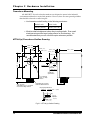
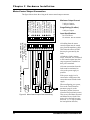
Motor Control Output Connections
2762-17 Front Panel
Maximum Output Current
2 Adc per Output
5 Adc per Channel
Surge Rating (10 mSec)
4 Adc per Output
Input Specifications
10 to 24 Vdc/ac
10 mA max. turn on current
LOAD 8 +
LOAD 7 +
LOAD 6 +
-
LOAD 5 +
+
-
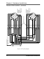
Figure 3.5 Motor Control Output Connector Wiring
42
All cabling from the motor
control outputs must be routed
away from the transducer cable.
This limits the effects of EMI
that may be generated by the
loads.
All inductive loads, (motors,
relays, solenoids, etc.) connected
to the control outputs must have
surge suppressors installed on
their power terminals.
All return connections from the
loads must be terminated as
close to the power supply as
possible.
If the power supply is to be
connected to earth ground, the
connection must be made at the
supply.
POWER
SUPPLY
12-40 Vdc
LOAD 1 +
POWER
SUPPLY
12-40 Vdc
+
-
-
-
LOAD 2 +
-
LOAD 3 +
-
LOAD 4 +
AMCI Part #: MS-141
Weidmüller Part #: 128291
+
POWER
SUPPLY
10-24 Vac/dc
MOMENTARY OR SPST SWITCH
MOTOR CONTROL
OUTPUT CONNECTOR
14
13
12
11
10
9
8
7
6
5
4
3
2
1
+ External Jog Input
– External Jog Input
VIN 1 / Fuse Indicator
CH 1 Motor Forward
CH 1 Motor Reverse
CH 1 High Speed
CH 1 Low Speed
VIN 1 Common
VIN 2 / Fuse Indicator
CH 2 Motor Forward
CH 2 Motor Reverse
CH 2 High Speed
CH 2 Low Speed
VIN 2 Common
The figure below shows the wiring to the motor control output connector.
When configuring you system,
first set the Count Direction
parameter (page 8) so the
transducer position increases
when the load position increases.
Then reverse the Motor Forward
and Motor Reverse leads if the
motor drives the load in wrong
direction. (i.e. A Jog Up makes
the load position decrease.)
ADVANCED MICRO CONTROLS INC.
Chapter 4
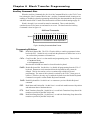
AMCI Module Addressing
This chapter explains how to address a 2762-17 in a programmable controller system.
Remember that a 2762-17 performs concurrent block and single transfers.
When you configure your programmable controller system, you specify a unique address for each slot
of each chassis in the system. An I/O Rack number and an I/O Group Number make up each address. A
Module Slot number further specifies a block transfer address.
Note that an I/O Chassis is not the same as an I/O Rack. An I/O Chassis is the physical
enclosure that the processor and I/O modules plug into. An I/O Rack Number is part of a
modules' address in the system. Each I/O Chassis can have ¼ to 4 I/O Racks associated with it.
Definition of Terms
Block Transfer
The transfer of a block of data over the backplane in one scan. A Block Transfer Read
transmits data from an I/O module to the processor. A Block Transfer Write transmits data
from the processor to an I/O module. Up to sixty-four words can be transmitted per block
transfer. The 2762-17 requires block transfers of twelve words.
Single Transfer
The transfer of a single unit (8, 16, or 32 bits) of data over the backplane. The transfer
occurs between I/O Modules and the processors' Input or Output Image Tables. Single
transfers occur automatically every I/O scan and can occur during a program scan with the use
of Immediate Input and Immediate Output Instructions. In addition to using block transfers, the
2762-17 accepts and transmits single transfer data 16 bits at a time.
I/O Rack
The number of I/O Racks in the system, not the number of chassis, define the programmable controller system. In PLC-5 systems the first I/O Rack is assigned the number 0. Each
I/O Rack is further divided into 8 I/O Groups.
When specifying a block transfer or single transfer address all I/O Rack and
Group numbers are expressed in octal. (i.e. 00, 01, 02, ... 06, 07, 10, 11, ......)
I/O Group
An I/O Group consists of 16 input and 16 output bits. Eight I/O Groups, numbered 0
through 7, make up a single I/O Rack.
Slot Pair
Backplane slots of an I/O Chassis are numbered consecutively from zero starting at the
leftmost I/O slot. A slot pair is two adjacent backplane slots, the left of which is even
numbered. Most A-B chassis have the slots numbered on the backplane silk screen.
A 2762-17 module must be installed in a single slot pair to operate properly. See
Installing the Module, Pg. 37. The figures in this chapter show the module in a Slot Pair.
ADVANCED MICRO CONTROLS INC.
43
Chapter 4
AMCI Module Addressing
Definition of Terms (cont'd)
2-Slot Addressing
Two slot addressing cannot be used with the 2762-17 module. Two slot addressing assigns
one I/O group to a slot pair in the chassis. A minimum of two I/O groups (32 I/O bits) must be
assigned to the slot pair so the 2762-17 can perform concurrent single and block transfers.
1-Slot Addressing
With 1-slot addressing, one I/O group (16 I/O bits) is assigned to each slot in the chassis.
Therefore the 2762-17 has two I/O groups to use, one in each slot of its slot pair. The 2762-17
uses the first I/O group to control its block transfers and the second I/O group for its single
transfers.
½-Slot Addressing
With ½-slot addressing, two I/O groups (32 I/O bits) are assigned to each slot in the chassis.
Therefore the 2762-17 has four I/O groups to use, two in each slot of its slot pair. The 2762-17
uses the first I/O group to control its block transfers and the second I/O group for its single
transfers. The third and fourth I/O groups are not used.
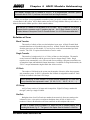
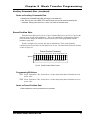
Addressing the Block Transfer Data
The PLC reads operating data from the 2762-17 module with block transfer read (BTR)
instructions and programs the setup parameters with block transfer write (BTW) instructions.
The block transfer address is made up of four digits. They are the I/O Rack Number (two
digits), the I/O Group Number (one digit), and the Module Slot Number (one digit, always 0).
Note: The I/O Group number used for block transfers is always the lowest, even
numbered I/O Group assigned to the Slot Pair the 2762-17 resides in.
M O D U LE A D D R E S S = R G S
I/O R ack N um b er
I/O G roup N um ber
M odule Slo t N um ber
Fig 4.1 BT Module Address
44
ADVANCED MICRO CONTROLS INC.
Chapter 4
AMCI Module Addressing
Addressing the Single Transfer Data
The processor writes commands and reads status data from the 2762-17 with single
transfers. To communicate using single transfers you must know the memory locations in the
output and input image tables associated with the module.
!
!
PLC-5 Input Table: The characters "I:" followed by a three digit number. The
first two digits are the I/O rack number, followed by the I/O
group number.
Output Table: The characters "O:" followed by a three digit number. The
first two digits are the I/O rack number, followed by the I/O
group number.
Note: The I/O group number used for single transfers is always the lowest, odd
numbered I/O group assigned to the Slot Pair the 2762-17 resides in.
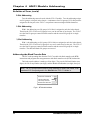
Addressing Examples
The following are examples of module addressing for 1-Slot and ½-Slot configurations.
The PLC-5 addresses for block and single transfers are also shown.
In the following figures, the module is placed in a single slot pair. See Installing the
Module Pg. 37 for more information.
The 2762-17 must be installed in a single slot pair to operate properly.
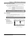
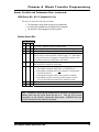
1-Slot Addressing
Rack Number: 01
I/O Group Numbers: 0,1
Module Slot Number: 0
I/O G ro u p
N u m be r
I/O R ack N um be r 0
0 1
2 3
0
0
4 5
6 7
I/O R ack N um be r 1
0 1
2 3
4 5
6 7
0
0
PLC-5 BT Address = 0100
PLC-5 Single Addr = I:011
0
0
0 0 0 0 0 0 0
M odule S lot N um bers
0
0
0
Fig 4.2 2762-17 1-Slot Address
ADVANCED MICRO CONTROLS INC.
45
Chapter 4
AMCI Module Addressing
Addressing Examples (cont'd)
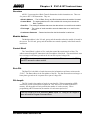
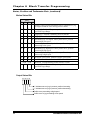
½-Slot Addressing
Rack Number: 02
I/O Group Numbers: 0,1,2,3
Module Slot Number: 0
I/O G ro u p
N u m be r
I/O R a ck 0
0,1 2,3
I/O R ack 1
4,5 6,7
0,1 2,3
4,5 6,7
I/O R a ck 2
0,1 2,3
I/O R ack 3
4,5 6,7
0,1 2,3
4,5 6,7
PLC-5 BT Address = 0200
PLC-5 Single Addr = I:021
0
0
0
0
0 0 0 0 0 0 0
M odule S lot N um bers
0
0
0
0
0
Fig 4.3 2762-17 ½-Slot Address
Restrictions and Warnings
1. The 2762-17 must be installed in a single slot pair in order to operate properly. See
Installing the Module Pg. 37.
2. The 2762-17 module cannot be installed in a chassis set-up for 2-Slot addressing.
3. When using a 2762-17 in a Remote I/O chassis, the I/O Adapter must be a 1771 ASB, Series B, Firmware Rev. F, or later. Using a Remote I/O Adapter that has an
earlier Series or Firmware Revision may not work properly with the 2762-17 module.
46
ADVANCED MICRO CONTROLS INC.
Chapter 5 PLC-5 BT Instructions
Overview
All PLC-5 processors have Block Transfer Instructions in their instruction sets. There are
five parts to PLC-5 BT Instructions. They are:
!
!
!
!
!
Module Address - The I/O Rack, Group, and Slot Numbers where the module is located.
Control Block - The starting address of the five word block in memory that controls the
Block Transfer.
Data File - The starting file address that stores the data written to or read from the module.
File Length - The number of words needed to store the data written to or read from the
module.
Continuous Parameter - Determines how often the block transfer is carried out.
Module Address
The Module address is the I/O rack, group, and slot numbers where the module is located in
the system. The I/O rack, group, and slot numbers are entered separately in the block transfer
instruction.
Control Block
The Control Block is a block of five words that control the actual transfer of data. The
address entered into the BT instruction is the first address of the block. The control block must
have an integer or BT data type and can be its own file or part of a larger file.
Each BT Instruction requires a separate control block. This is true even if a BTW
and BTR access the same module.
Data File
The Data File is the block of words that stores the information read from or written to the
2762-17. The Data Address is the first address of the file. The data file must have an integer or
binary data type and can be a separate file or part of a larger file.
File Length
The File Length is the number of words in your data file. When programming a BTR
instruction, you can set the Block Length to 00. This will reserve 64 words in the PLC-5
memory, but the module will only transmit the number of words necessary. When
programming a BTW instruction, the number of words must equal twelve.
The File Length of a BTW instruction MUST equal 12. Using a File Length of
zero will cause a Program Command Error.
ADVANCED MICRO CONTROLS INC.
47
Chapter 5
PLC-5 BT Instructions
Continuous Parameter
The Continuous parameter controls how often the block transfer instruction is executed.
When the continuous parameter is set to "NO", the block transfer is executed only on a false to
true transition on the rung. This means that a non-continuous block transfer can occur at most
every other scan. When the continuous parameter is set to "YES", the block transfer will occur
when the BT instruction is first scanned and then every scan thereafter until an error in communication occurs.
Block Transfer Writes to the 2762-17 module MUST have the Continuous
Parameter set to NO. Continuously writing Program Instructions to the module
may intefere with normal module operation. Block Transfer Reads to the 276217 can have their Continuous Parameter set to "YES".
Enable (EN), Error (ER), and Done (DN) Bits
Used to signal the start and finish of a block transfer, the processor sets the EN bit to start
the transfer and after successfully completing the transfer the module sets the DN bit. If an
error occurs in the transfer, the module will set the ER bit instead of the DN bit.
The EN, ER, and DN bits are located in the first word of the Control File. The EN Bit is bit
15, the ER Bit is bit 12 and the DN Bit is bit 13.
The following warning is taken verbatim from Allen-Bradley's PLC-5 Family
Programmable Controllers Processor Manual, Publication 1785-6.8.2 - November, 1987 and
refers to the control bits of the BT instruction. These bits include the Enable, Error, and Done
bits.
"IMPORTANT: The processor executes block-transfer instructions asynchronous to the program scan. The status of these bits could change at any point in
the program scan. When you test these bits (especially the done bit), test them
only once every ladder program scan. If necessary, set temporary storage bits
for the purpose of enabling subsequent rungs from them.
Also, your ladder program should condition the use of block transfer data on the
examination of the block-transfer error bit. An error may occur when the
processor is switched from run mode, or when processor communications are
interrupted."
48
ADVANCED MICRO CONTROLS INC.
Chapter 5 PLC-5 BT Instructions
Programming Example
The following example assumes 1-Slot addressing and the 2762-17 module is I/O Rack 2,
I/O Groups 4 & 5 of the system.
BLOCK XFER READ
RACK
2
GROUP
4
MODULE
0
CONTROL
N7:20
DATA
N7:25
LENGTH
12
CONTINUOUS Y
(EN)
(ER)
(DN)
Rung 2: Copy File Instruction buffers
the data from the module. This
insures that the program will
use the same data throughout
each scan.
COP
COPY FILE
SOURCE
DEST
LENGTH
CR1
#N7:25
#N7:40
12
BLOCK XFER WRITE
RACK
2
GROUP
12
MODULE
0
CONTROL
N14:0
DATA
N14:5
LENGTH
12
CONTINUOUS N
BTW Request
(EN)
(ER)
CR1
CR1
BTW
(U)
DN
Rung 3: The BT write is enabled whenever CR1 is latched on. Note
that the continuous parameter
is set to NO.
(DN)
(L)
BTW Request
Rung 1: BTR Instruction to the AMCI
module. Data will be
transferred every scan with
continuous transfer enabled.
Rung 4: CR1 is latched on when a
BTW request is made.
Rung 5: CR1 is unlatched when the
BTW request is removed and
the BTW Done bit is set.
Fig 5.1 PLC-5 Programming Example
ADVANCED MICRO CONTROLS INC.
49
Chapter 5
PLC-5 BT Instructions
PLC-5 Restrictions and Warnings
! W A R N IN G
The following restrictions must be followed when using the 276217 in a PLC-5 System. If these restrictions are not followed,
unpredictable operation may occur.
1. The 2762-17 will not operate in a chassis configured for 2-Slot addressing. The chassis must
be configured for 1-Slot or ½-Slot addressing.
2. The 2762-17 module must be installed in a single slot pair. (See chapter 3, Installing the
Module, page 37.) If it is not installed correctly, the module will not be able to perform
concurrent block and single transfers.
3. When using the 2762-17 in a remote chassis, the Remote I/O Adapter must be a 1771 - ASB,
Series B, Firmware Rev. F, or later. Using a Remote I/O Adapter that has an earlier Series or
Firmware Revision may not work properly with the 2762-17.
4. When the processor enables a block transfer, it puts all of the needed information into a queue.
A queue is a data structure where the first piece of information put into the queue is the first
piece of information taken out. Once the information is queued, a separate part of the
processor performs the block transfer while the rest of the processor continues with the
program scan. Each I/O rack in the system has it's own queue. Each queue can hold 17 BT
requests. When the block transfer has its Continuous bit set to 1, Continuous Parameter is
"YES", the Block Transfer is placed permanently in the queue.
Each queue has a "Queue Full" bit in word 7 of the processor's status file. Bit 8 is for Rack 0,
Bit 9 is for Rack 1, and so on up to bit 15 for Rack 7. The appropriate bit is set when a queue
is full of BT Requests. Once set, your ladder logic program must clear these bits. We recommend that your program monitor these bits and take appropriate action if these bits are set.
Note: If you have more than 17 block transfers associated with one rack and you set all of their
continuous parameters to YES, only the first 17 block transfers scanned will be
performed. All other transfers cannot be put into the queue and will never be performed.
50
ADVANCED MICRO CONTROLS INC.
Chapter 6
Block Transfer Programming
This chapter describes the format of the data written to and read from the 276217 using BTW and BTR instructions. It assumes familiarity with the setup and
operation of the 2762-17. Descriptions of the modules' parameters given in
chapter 1 are not repeated here. However, the default, minimum and maximum
values that can be programmed are listed. If you are not familiar with the
operation of the 2762-17, review chapters 1 and 2 before proceeding.
Block Transfer Writes
In addition to the keyboard, every 2762-17 parameter can be programmed with block
transfer writes (BTW). Programming from the keyboard can also be disabled. Follow these
guidelines when using block transfer writes.
!
!
!
!
!
!
BTW length is always 12 words. Do not set the length to zero when programming the BTW.
Any unused words in the block transfer should be considered reserved and set to zero.
All parameter values, (Full Scale Count, Linear Offset, etc.) must be transferred in binary
format. Before entering data in the data table set the radix to decimal.
Most of the 2762-17 parameters can exceed ±32,768. Therefore they require two words to
hold the data. The thousands digits must be transferred in the first word, the ones, tens, and
hundreds digits must be transferred in the second word. For example, a Full Scale Count of
368,640 would be transferred as 368 in the first word and 640 in the second word.
Negative values are transmitted in sign-magnitude format. The MSB of the first word of the
parameter is the sign bit. To enter a negative value set the data table radix to decimal and
enter the absolute value of the parameter. Next, switch the radix to binary and set the MSB
of the first word.
Once a block transfer write to the 2762-17 has completed, (i.e. The DONE Bit is set),
perform a block transfer read to input the status, position and tach data of the module.
Check the error bits and take appropriate action if an error has occurred.
If there is an error in the data sent to the 2762-17, the module responds by setting the
appropriate error bits and ignores all of the data sent to it with the block transfer write.
BTW Command Word
The first word of a BTW is the Command Word. As shown in figure 6.1, setting a bit in the
upper byte of the Command Word tells the 2762-17 which parameters are transferred in the
remaining eleven words. Note that only one bit can be set per block transfer. The meaning of
the lower byte changes, and is explained in later sections.
Command Word
15 14 13 12 11 10 09 08 07 06 05 04 03 02 01 00
0 0 0 0
Transducer Setup
Positioning Setup
Auxiliary Commands
Preset Transducer Position
RESERVED: Must equal zero.
Fig. 6.1 Command Word Format
ADVANCED MICRO CONTROLS INC.
51
Chapter 6
Block Transfer Programming
Transducer Setup Data
When the Transducer Setup bit, (bit 8) of the Command word is set, the 2762-17 uses the
rest of the data to configure the transducer specified by the LSB of the Command Word.
Configuring both transducers requires two block transfers. Transducer Setup programs the
parameters shown below. The data format is shown in figure 6.2.
!
!
!
Transducer Type
Number of Turns
Preset Value
!
!
!
Count Direction
Scale Factor
Upper Travel Limit
!
!
!
Decimal Point
Linear Offset
Lower Travel Limit
Transducer Setup Command
Decimal
Point
ChNm
0 0 0 0 0 0 0 1 0 0
TType
Word 0
DIR
15 14 13 12 11 10 09 08 07 06 05 04 03 02 01 00
Number of Turns
Word 2
Upper 1, 2 or 3 digits: Scale Factor
Word 3
Lower 3 digits: Scale Factor
Word 4
SGN
Word 1
Upper 1, 2 or 3 digits: Linear Offset
Lower 3 digits: Linear Offset
Word 6
SGN
Word 5
Upper 1, 2 or 3 digits: Preset Value
Lower 3 digits: Preset Value
Word 8
SGN
Word 7
Upper 1, 2 or 3 digits: Upper Travel Limit
Lower 3 digits: Upper Travel Limit
Word 10
SGN
Word 9
Upper 1, 2 or 3 digits: Lower Travel Limit
Word 11
Lower 3 digits: Lower Travel Limit
Fig 6.2 Transducer Setup Command Data Format
Programming Bit Values
ChNum: Channel Number Bit. Set to 0 to program transducer channel one or set to 1 to
program transducer channel two.
52
TType:
Transducer Type Bit. Set to 0 if programming for an HTT-20-100 or set to 1 if
programming for an HTT-20-180.
DIR:
Direction Bit: Set to 0 if you want the count to increase with a clockwise rotation of
the transducer shaft or set to 1 if you want an increase with a counter-clockwise
rotation.
ADVANCED MICRO CONTROLS INC.
Chapter 6
Block Transfer Programming
Transducer Setup Data (continued)
Programming Bit Values (continued)
Decimal Point: Bits five, four, and three define a binary number that sets the number of digits
to the right of the decimal point on the 2762-17 display. This parameter has
no affect on the data transmitted over the backplane.
5
0
0
0
0
1
1
1
1
Bit #
4
0
0
1
1
0
0
1
1
3
0
1
0
1
0
1
0
1
= 0 (xxxxxx)
= 1 (xxxxx.x)
= 2 (xxxx.xx)
= 3 (xxx.xxx)
= 4 (xx.xxxx)
= 5 (x.xxxxx)
Undefined
Undefined
SGN: Sign Bit: Set to 0 if the corresponding value is positive or set to 1 if the value is
negative.
Ranges and Factory Default Values
Parameter
Range
Factory Default
Transducer Type
HTT-20-180, HTT-20-100
HTT-20-180
Count Direction
CW increasing, CCW increasing.
CW increasing
Decimal Point
0 to 5 inclusive
0
Number of Turns
HTT-20-180: 0.1 to 180.0, 0.1 turn resolution
HTT-20-100: 0.1 to 100.0, 0.1 turn resolution
180.0
Scale Factor
2 to (Number of Turns * 4,096)
737,280
Linear Offset
-99,999 to (999,999 - FSC† )
0
Preset Value
Linear Offset to (Linear Offset + FSC† )
0
Upper Travel Limit (Lower Travel Limit + 1) to (Linear Offset + FSC† ) 737,279
Lower Travel Limit Linear Offset to (Upper Travel Limit - 1)
0
† FSC: Full Scale Count = (Transducer Type {100 or 180} * (Scale Factor/Number of Turns)) - 1
ADVANCED MICRO CONTROLS INC.
53
Chapter 6
Block Transfer Programming
Positioning Setup Data
When the Positioning Setup bit, (bit 9) of the Command word is set, the 2762-17 uses the
rest of the data to configure the positioning data of the transducer specified by the LSB of the
Command Word. Configuring both transducers requires two block transfer writes. Positioning
Setup programs the parameters shown below. The data format is shown in figure 6.3.
!
!
Positioning Direction
Low Speed Offset
!
!
Target Position
Stop Offset
!
!
Overshoot Offset
Target Range
Positioning Setup Command
Word 1
ChNm
0 0 0 0 0 0 1 0 0 0 0 0 0 0
PDir
Word 0
SGN
15 14 13 12 11 10 09 08 07 06 05 04 03 02 01 00
Upper 1, 2 or 3 digits: Target Position
Word 2
Lower 3 digits: Target Position
Word 3
Upper 1, 2 or 3 digits: Overshoot Offset
Word 4
Lower 3 digits: Overshoot Offset
Word 5
Upper 1, 2 or 3 digits: Low Speed Offset
Word 6
Lower 3 digits: Low Speed Offset
Word 7
Upper 1, 2 or 3 digits: Stop Offset
Word 8
Lower 3 digits: Stop Offset
Word 9
Upper 1, 2 or 3 digits: Target Range
Word 10
Lower 3 digits: Target Range
Word 11
Retry Value
Fig. 6.3 Positioning Setup Command Data Format
Programming Bit Values
ChNum: Channel Number Bit. Set to '0' to program channel one positioning data or set to '1'
to program channel two positioning data.
54
PDir:
Positioning Direction Bit. Set to '0' to approach the Target Position from a position
greater than the Target Position, a "positive approach". Set to '1' to approach the
Target Position from a position less than the Target Position, a "negative approach".
SGN:
Sign Bit: Set to 0 if the Target Position is positive or set to 1 if the value is
negative.
ADVANCED MICRO CONTROLS INC.
Chapter 6
Block Transfer Programming
Positioning Setup Data (continued)
Ranges and Factory Default Values
Parameter
Range
Factory Default
Target Position
Linear Offset to (Linear Offset + FSC† )
0
Overshoot Offset
(Low Speed Offset + 1) to Full Scale Count†
1,000
Low Speed Offset
0 and (Stop Offset + 1) to (Overshoot Offset - 1)
500
Stop Offset
1 to (Overshoot Offset - 1) if Low Speed = 0
1 to (Low Speed -1) if Low Speed ≠ 0
100
Target Range
0 to Full Scale Count†
0
Retry Value
1 to 255
3
Notes on Positioning Data
!
!
!
!
!
Overshoot Offset, Low Speed Offset, Stop Offset, and Target Range are defined as being
relative to the Target Position and are programmed as absolute values. If the Positioning
Direction Bit defines a positive approach, the values are added to the Target Position. If the
Positioning Direction Bit defines a negative approach, the values are subtracted from the
Target Position.
The Positioning Direction Bit defines the direction of the approach to the Target Position,
either a positive or neagtive approach. It is possible for the starting position of the move
profile to be on the opposite side of the Target Position. (The starting position is less than
the Target Position and a positive approach is programmed, or visa versa.) If this is the
case, the 2762-17 will drive the motor to (Target Position ± Overshoot Offset) and remove
power. Once the motor has coasted to a stop, the 2762-17 completes the profile with the
defined approach.
Setting the Low Speed Offset to zero disables high speed motion.
The range checking listed in the above table is performed when the data is entered.
However the data may not define a valid profile. As an example, (Target Position +
Overshoot Offset) may exceed the Upper Travel Limit. Profile checking is not performed
until a profile move is requested. If the profile cannot be performed, a Profile Error message
is sent to the processor through the single transfer input data. For more information on the
single transfer input data refer to Single Transfer Input Data, chapter 7, page 66.
The Retry Value applies only to move profiles initiated from the backplane.
† FSC: Full Scale Count = (Transducer Type {100 or 180} * (Scale Factor/Number of Turns)) - 1
ADVANCED MICRO CONTROLS INC.
55
Chapter 6
Block Transfer Programming
Auxiliary Commands Data
When the Auxiliary Commands bit, (bit 10) of the Command Word is set, the 2762-17 uses
bits 0 through 6 of the Command Word as data. Auxiliary Commands include clearing errors,
enabling or disabling keyboard programming and defining the data transmitted to the processor
with block transfer reads. Format of the block transfer read data is defined starting on page 58.
Words 1 through 11 are not used but must be transmitted. These words should be
considered reserved for future use and must be set to zero. The data format for Auxiliary
Commands is show in figure 6.4
Additional Commands
RBC
ClrErr
DisKB
RSP
EnKB
0 0 0 0 0 1 0 0 0
RTS
Word 0
RPS
15 14 13 12 11 10 09 08 07 06 05 04 03 02 01 00
Words 1-11 RESERVED: Must equal zero.
Fig 6.4 Auxiliary Commands Data Format
Programming Bit Values
RBC:
Read Back Channel Bit. The 2762-17 has the ability to send its programmed values
back to the PLC. Set this bit to 0 to read back the parameters of channel one or set to
1 to read back the parameters of channel two.
ClrErr: Clear Errors Bit. Set to 1 to clear module and programming errors. These include:
!
!
Transducer Faults
All Programming Errors
Note that the NvRAM error must be cleared from the keyboard.
DisKB: Disable Keyboard Bit. Set this bit to 1 to disable all programming from the 2762-17
keyboard. Parameters can be monitored from the keyboard but they cannot be
changed. This bit does not have to be set continuously to disable keyboard
programming. The status of the keyboard is retained by the 2762-17 when power is
removed. Therefore, the only way to enable the keyboard once the Disable Keyboard
Command is accepted is with an Enable Keyboard command.
EnKB: Enable Keyboard Bit. Set this bit to 1 to counteract a previous Disable Keyboard
command.
56
RSP:
Read Status and Position Bit. Set this bit to 1 to read back module status with position
and tachometer data of both transducers.
RTS:
Read Transducer Setup Bit. Set this bit to 1 to read back Transducer Setup data of the
transducer specified by the RBC bit (bit 00).
RPS:
Read Positioning Setup Bit. Set this bit to 1 to read back Positioning Setup data of the
transducer specified by the RBC bit (bit 00).
ADVANCED MICRO CONTROLS INC.
Chapter 6
Block Transfer Programming
Auxiliary Commands Data (continued)
Notes on Auxiliary Commands Data
!
!
Setting both the DisKB and EnKB will cause a command error.
One, and only one of the RSP, RTS, and RPS bits must be set when transmitting this
command. Setting more than one, or none, will cause a command error.
Preset Position Data
When the Preset Position bit, (bit 11) of the Command Word is set, the 2762-17 presets the
position of one or both of the transducers. This is accomplished by calculating the internal
offset needed to change the transducer position to the preset value programmed with the
transducer setup data.
Words 1 through 11 are not used, but must be transmitted. These words should be
considered reserved for future use and must be set to zero. The data format for Preset Position
is show in figure 6.5
Preset Position Command
0 0 0 0 1 0 0 0 0 0 0 0 0 0
PS1
Word 0
PS2
15 14 13 12 11 10 09 08 07 06 05 04 03 02 01 00
Words 1-11 RESERVED: Must equal zero.
Fig 6.5 Preset Position Data Format
Programming Bit Values
PS1: Preset Transducer 1 Bit. Set this bit to 1 to alter the position data of channel one to its
preset value.
PS2: Preset Transducer 2 Bit. Set this bit to 1 to alter the position data of channel two to its
preset value.
Notes on Preset Position Data
!
Both transducers can be preset with one command.
ADVANCED MICRO CONTROLS INC.
57
Chapter 6
Block Transfer Programming
Block Transfer Reads
Use block transfer reads to transfer complete module status to the processor. The block
transfer is always twelve words long. The block transfer data takes one of three forms.
!
!
!
Status, Position and Tachometer data
Transducer Setup data
Positioning Setup data.
On power up, the 2762-17 transmits status, position and tachometer data. Use the Auxiliary
Commands command with the RTS or RPS bit set to read the other types of data. (For a full
description of the Auxiliary Commands command, see Pg. 56.)
Status, Position and Tachometer Data
The format of the status, position and tachometer data is shown in figure 6.6. Words 0 and 6
contain the status bits. Word 0 contains the status bits for channel 1 and word 6 contains the
status bits for channel 2. The forma of the two words is identical. The tables on the following
page lists the meanings of the status bits.
Status, Position and Tachometer Data
0 0 0
Word 1
KBIN
Word 0
SGN
15 14 13 12 11 10 09 08 07 06 05 04 03 02 01 00
0
Module
Status
Motion
Status
Output
Status
Upper 1, 2 or 3 digits: Position 1
Word 2
Lower 3 digits: Position 1
Word 3
Upper 1, 2 or 3 digits: Tachometer 1
Word 4
Lower 3 digits: Tachometer 1
Transducer 2 Status Word
Word 6
SGN
Word 5
Upper 1, 2 or 3 digits: Position 2
Word 7
Lower 3 digits: Position 2
Word 8
Upper 1, 2 or 3 digits: Tachometer 2
Word 9
Lower 3 digits: Tachometer 2
Word 10
Not used. Set equal to 0000.
Word 11
Not used. Set equal to 0000.
Fig 6.6 Status, Position, and Tachometer Data Format
58
ADVANCED MICRO CONTROLS INC.
Chapter 6
Block Transfer Programming
Status, Position and Tachometer Data (continued)
KBIN Status Bit: Bit 12, Keyboard In Use
This bit is set under the following conditions.
!
!
!
The keyboard is being used to program any parameter.
A move profile initiated from the keyboard is in progress.
The position is being jogged from the keyboard.
Module Status Bits
Bit #
10 09 08
0
0
0
0
0
1
0
1
0
0
1
1
1
0
0
1
0
1
1
1
1
1
0
1
No Errors. Module operating without errors.
Transducer Fault. There is a transducer fault or wiring error.
NvRAM Error. Parameters have not been stored correctly.
Program Command Error. Indicates error in the programming
bits of word 0 of the last BTW or BTW length ≠ 12. When there
is an error that forces a Program Command Error response, this
bit pattern is placed in both Word 0 and Word 6.
Program Parameter Error. Indicates that a parameter sent with
the last BTW is outside its valid range.
Command Ignored.
1) Attempted to program while there is a NvRAM error.
2) Attempted to program while any parameter is being edited
from the keyboard.
3) Attempted to program while a move profile is running.
4) Attempted to preset a position, jog the position, or run a
move profile while the channel is in transducer fault.
Reserved
Reserved
Note: Transducer Faults can be cleared with an Auxiliary Commands block
transfer write with the Clear Errors Bit set to 1. See Pg 56 for more
information on the Auxiliary Commands data format. NvRAM Errors can
only be cleared from the modules’ keyboard.
ADVANCED MICRO CONTROLS INC.
59
Chapter 6
Block Transfer Programming
Status, Position and Tachometer Data (continued)
Motion Status Bits
07
Bit #
06 05
04
0
0
0
0
Stopped. Move profile terminated before it completed or a jog
is stopped within the lower and upper travel limits.
0
0
0
1
Stopped, In Position. The present position is within the
specified Target Range.
0
0
1
0
Jogging Up. Position is manually forced to increase
0
0
1
1
Jogging Down. Position is manually forced to decrease.
0
1
0
0
Positioning Up, Low Speed. Move profile active, position
increasing at low speed.
0
1
0
1
Positioning Down, Low Speed. Move profile active, position
decreasing at low speed.
0
1
1
0
Positioning Up, High Speed. Move profile active, position
increasing at high speed.
0
1
1
1
Positioning Down, High Speed. Move profile active, position
decreasing at high speed.
1
0
0
0
At Upper Travel Limit. Position"#"Upper Travel Limit.
1
0
0
1
At Lower Travel Limit. Position ≤ Lower Travel Limit.
1010 - 1110
1
1
1
Reserved. Not implemented in this software revision.
1
Stopped, Not In Position. The present position is not within the
specified Target Range.
Output Status Bits
03 02 01 00
'1' indicates move or jog in process, position increasing.
'1' indicates move or jog in process, position decreasing.
Profile move proceeding at high speed.
Profile move or jog proceeding at low speed.
60
ADVANCED MICRO CONTROLS INC.
Chapter 6
Block Transfer Programming
Transducer Setup Read Back Data
When you send an Auxiliary Commands command with the RTS (Read Transducer Setup)
bit set, the 2762-17 responds by echoing back the Transducer Setup data. The Channel
Number bit (bit 00) of the Auxiliary Commands command determines which transducer data is
set. Therefore it requires two BTW/BTR sequences to read all of the Transducer Setup data.
The format of the data is shown below in figure 6.7. Note that read back data has bit 15 of
word 0 set to '1'.
Transducer Setup Read Back
Decimal
Point
ChNm
1 0 0 0 0 0 0 1 0 0
TType
Word 0
DIR
15 14 13 12 11 10 09 08 07 06 05 04 03 02 01 00
Number of Turns
Word 2
Upper 1, 2 or 3 digits: Scale Factor
Word 3
Lower 3 digits: Scale Factor
Word 4
SGN
Word 1
Upper 1, 2 or 3 digits: Linear Offset
Lower 3 digits: Linear Offset
Word 6
SGN
Word 5
Upper 1, 2 or 3 digits: Preset Value
Lower 3 digits: Preset Value
Word 8
SGN
Word 7
Upper 1, 2 or 3 digits: Upper Travel Limit
Lower 3 digits: Upper Travel Limit
Word 10
SGN
Word 9
Upper 1, 2 or 3 digits: Lower Travel Limit
Word 11
Lower 3 digits: Lower Travel Limit
Fig 6.7 Read Back Transducer Setup Data
ADVANCED MICRO CONTROLS INC.
61
Chapter 6
Block Transfer Programming
Positioning Setup Read Back Data
When you send an Auxiliary Commands command with the RPS (Read Positioning Setup)
bit set, the 2762-17 responds by echoing back the Positioning Setup data. The Channel
Number bit (bit 00) of the Auxiliary Commands command determines which positioning data is
set. Therefore it requires two BTW/BTR sequences to read all of the Positioning Setup data.
The format of the data is shown below in figure 6.8. Note that read back data has bit 15 of
word 0 set to '1'.
Positioning Setup Read Back
Word 1
PDir
1 0 0 0 0 0 1 0 0 0 0 0 0 0
ChNm
Word 0
SGN
15 14 13 12 11 10 09 08 07 06 05 04 03 02 01 00
Upper 1, 2 or 3 digits: Target Position
Word 2
Lower 3 digits: Target Position
Word 3
Upper 1, 2 or 3 digits: Overshoot Offset
Word 4
Lower 3 digits: Overshoot Offset
Word 5
Upper 1, 2 or 3 digits: Low Speed Offset
Word 6
Lower 3 digits: Low Speed Offset
Word 7
Upper 1, 2 or 3 digits: Stop Offset
Word 8
Lower 3 digits: Stop Offset
Word 9
Upper 1, 2 or 3 digits: Target Range
Word 10
Lower 3 digits: Target Range
Word 11
Retry Value
Fig 6.8 Read Back Positioning Setup Data
62
ADVANCED MICRO CONTROLS INC.
Chapter 7 Single Transfer Programming
This chapter describes the format of the data written to and read from the
2762-17 using single transfers. This data is stored in the processors output and
input data tables. This chapter assumes familiarity with the setup and operation
of the module. If you are not familiar with the operation of the 2762-17, review
chapters 1 and 2 before proceeding.
Single Transfer Data
You issue the following commands to the 2762-17 with single transfer output data.
!
!
!
!
!
!
Start Move Profile
Stop Move Profile
Jog Up
Jog Down
Set jog direction for external jog input
Enable / Disable external jog input
Single transfer output data is written to the 2762-17 via the processors' output image table.
Simply move the data to the modules address in the table and the processor will transfer the
data to the 2762-17 at the end of the program scan. You can also use immediate output
instructions in your ladder logic to update the module before the end of the program scan.
Single transfer input data gives you status information on the module and positioning
information for both channels. Single transfer input data is read by the processor before the
beginning of the program scan. You can also use immediate input instructions in your ladder
logic to update the status information during your program scan.
ADVANCED MICRO CONTROLS INC.
63
Chapter 7 Single Transfer Programming
Single Transfer Output Data
The format of the output data is shown in figure 7.1. Bits 0 - 7 control channel one and bits
10-17 control channel two. Note that these bits are numbered in octal. Bit addresses in the I/O
data tables are in octal.
Single Transfer Output Data
17 16 15 14 13 12 11 10 07 06 05 04 03 02 01 00
0 0
0 0
CHANNEL 1 CONTROL BITS
Start Move Profile
Stop Move Profile
Jog Up
Jog Down
External Jog Input Direction
"0" = up "1" = down
Enable Manual Jog
"0" = Disable "1" = Enable
RESERVED: Must equal zero.
CHANNEL 2 CONTROL BITS
Start Move Profile
Stop Move Profile
Jog Up
Jog Down
External Jog Input Direction
"0" = up "1" = down
Enable Manual Jog
"0" = Disable "1" = Enable
RESERVED: Must equal zero.
Figure 7.1 Single Transfer Output Data Format.
64
ADVANCED MICRO CONTROLS INC.
Chapter 7 Single Transfer Programming
Single Transfer Output Data (continued)
Command Bits
Start Move Profile. CH1: Bit 0, CH2: Bit 10.
A 0 " 1 transition initiates a move profile.
Stop Move Profile. CH1: Bit 1, CH2: Bit 11.
A 0 " 1 transition immediately stops a move profile.
Jog Up. CH1: Bit 2, CH2: Bit 12.
Set this bit to travel at low speed towards the upper travel limit. Note that it is possible to
jog up past the programmed upper travel limit.
Jog Down. CH1: Bit 3, CH2: Bit 13.
Set this bit to travel at low speed towards the lower travel limit. Note that it is possible to
jog down below the programmed lower travel limit
External Jog Input Direction. CH1: Bit 4, CH2: Bit 14.
Reset this bit when the external jog input must initiate a jog up. Set this bit when the
external jog input must initiate a jog down. This bit is used with the Jog Enable bit.
Jog Enable. CH1: Bit 5, CH2: Bit 15.
Set this bit to enable the external jog input to jog the channels' position. Reset this bit to
disable the external jog input. If the external jog input is active when this bit is reset the
jog will stop immediately.
Valid Command Bit Combinations
The following table lists the valid command bit combinations with a brief description. All
other bit patterns cause a Program Command Error. Program Command Errors are reported to
the processor through block transfer read instructions and single transfer input data.
Bit # 7-0 or 17-10
"0 0 0 0 0 0 0 0"
Perform no change in action.
"0 0 0 0 0 0 0 1"
Start Move Profile.
"0 0 0 0 0 0 1 0"
Stop Move Profile.
"0 0 0 0 0 1 0 0"
Jog Up.
"0 0 0 0 1 0 0 0"
Jog Down.
"0 0 1 0 0 0 0 0"
Enable a manual jog up.
"0 0 1 1 0 0 0 0"
Enable a manual jog down.
The PLC-5 Bit Field Distribution (BTD) Instruction can be used to copy eight bits from a
source word to a destination word. Defining the above seven patterns in an integer file and
using the BTD instruction to copy them to the appropriate byte in the output image table is one
way of avoiding Program Command Errors.
ADVANCED MICRO CONTROLS INC.
65
Chapter 7 Single Transfer Programming
Single Transfer Input Data
The format of the input data is shown in figure 7.2. Bits 0 - 7 are status bits for channel one
and bits 17 - 10 are for channel two. Note that these bits are numbered in octal. Bit addresses
in the I/O data tables are in octal.
Single Transfer Input Data
KBIN
KBIN
17 16 15 14 13 12 11 10 07 06 05 04 03 02 01 00
Module
Motion
Module
Motion
Status
Status
Status
Status
Ch 2
Ch 2
Ch 1
Ch 1
Figure 7.2 Single Transfer Input Data Format
Motion Status Bits
Bit #
13/3 12/2 11/1 10/0
0
0
0
0
Stopped. Move profile terminated before it completed or
a jog is stopped within the lower and upper travel limits.
0
0
0
1
Stopped, In Position. The present position is within the
specified Target Range
0
0
1
0
Jogging Up. Position is manually forced to increase
0
0
1
1
Jogging Down. Position is manually forced to decrease.
0
1
0
0
Positioning Up, Low Speed. Move profile active,
position increasing at low speed.
0
1
0
1
Positioning Down, Low Speed. Move profile active,
position decreasing at low speed.
0
1
1
0
Positioning Up, High Speed. Move profile active,
position increasing at high speed.
0
1
1
1
Positioning Down, High Speed. Move profile active,
position decreasing at high speed.
1
0
0
0
At Upper Travel Limit. Position Upper Travel Limit.
1
0
0
1
At Lower Travel Limit. Position Lower Travel Limit.
1010 - 1110
1
66
1
1
Reserved. Not implemented in this software revision.
1
Stopped, Not In Position. The present position is not
within the specified Target Range.
ADVANCED MICRO CONTROLS INC.
Chapter 7 Single Transfer Programming
Single Transfer Input Data (continued)
Module Status Bits
Bit #
16/6 15/5 14/4
0
0
0
No Errors. Module operating without errors.
0
0
1
Transducer Fault. There is a transducer fault or wiring error.
0
1
0
NvRAM Error. Parameters have not been stored correctly.
0
1
1
Command Error. Indicates error in the single transfer output data.
1
0
0
Profile Error. Once a profile has been requested, this bit pattern is set
if the programmed profile could not be executed. Most common
cause is (Target Position ± Overshoot Position) exceeding Upper or
Lower Travel Limit.
1
0
1
Command Ignored.
1) Attempted any action while there is a NvRAM error.
2) Attempted a move profile or jog while any parameter is being
edited from the keyboard.
3) Issued any command while a move profile is active, even
another Start Move Profile command.
4) Attempted a move profile or to jog while the channel is in fault.
5) Attempted to run a move profile while transducer position
outside the range of upper and lower travel limits.
When there is an error that forces a Command Ignored response, this
bit pattern is placed in both bits 16-14 and 6-4
1
1
0
Reserved
1
1
1
Reserved
Note: Transducer Faults can be cleared with an Auxiliary Commands block
transfer write with the Clear Errors Bit set to 1. See Pg 56 for more information on the Auxiliary Commands data format. NvRAM Errors can only be
cleared from the modules’ keyboard.
KBIN Status Bit: Bits 17 and 7, Keyboard In Use
These bits are set under the following conditions.
!
!
!
The keyboard is being used to program any parameter.
A move profile initiated from the keyboard is in progress.
The position is being jogged from the keyboard.
ADVANCED MICRO CONTROLS INC.
67
Chapter 7 Single Transfer Programming
Notes
68
ADVANCED MICRO CONTROLS INC.
Chapter 8
Sample PLC-5 Program
The following ladder logic program is an example of how block transfer
instructions can be used to interface the 2762-17 module to a PLC-5. The block
transfer functionality allows the PLC to read Status, Position, Velocity data as
well as parameter values from the 2762-17. It also allows the PLC to program
all setup information, as well as perform any error handling.
The program shows how to read and buffer the data from a 2762-17 module, and how a
single block transfer write instruction can be used to send the various setup and control
functions to the module. This program also shows how to restrict all block transfer write
programming when the module's keyboard is in use. It also restricts all programming but
auxiliary commands programming when there is a block transfer read module status error.
The 2762-17 module transmits the motor control output status, whether the outputs are on or
off, to the PLC in the block transfer read data. However, this may not be fast enough for some
applications. Rungs 2:9 through 2:12 can be used to determine the channel 1 output status from
the Motion Status Bits located in the input image table. These rungs should only be used when
the direction parameter is set to 'Positive' or CW increasing readings.
ADVANCED MICRO CONTROLS INC.
69
Chapter 8
Sample PLC-5 Program
+----------------------------------------------------+
|
Allen-Bradley Company
|
|
6200 Series Software
|
|
PLC-5 Programming Terminal Software
|
|
Release 5.11
|
|
Program Listing Report
|
|
|
|
|
|
|
|
Processor File: 2762_17
|
|
Thu Feb 22, 1996 - 9:10:56 am
|
|
|
|
|
| REPORT OPTIONS
|
|
Page Width:
80
|
|
Page Length:
66
|
|
Graphics Capabilities:
NO
|
|
Right Power Rail:
YES
|
|
Address Display:
SYMBOL
|
|
Address Comments:
YES
|
|
Rung Comments:
YES
|
|
Output Cross Reference:
NO
|
|
Ladder Cross Reference:
NONE
|
|
Starting Rung:
2:0
|
|
Ending Rung:
999:32767
|
|
Formatting Commands:
ACTIVE
|
+----------------------------------------------------+
70
ADVANCED MICRO CONTROLS INC.
Chapter 8
Program Listing Report
PLC-5/11
Sample PLC-5 Program
Thu Feb 22, 1996
Page 1
File 2762_17
Rung 2:0
Rung 2:0
The output image table of a PLC-5 is not cleared at power up. To insure that
the 2762-17 module will not initiate any motion at power up, it is strongly
recommended that you clear the output image table on the first pass through
your ladder logic program.
| first
2762-17
|
| pass bit
module
|
|
S:1
+MOV---------------+ |
+----] [--------------------------------------------------+MOVE
+-+
|
15
|Source
0| |
|
|
| |
|
|Destination O:007| |
|
|
0| |
|
+------------------+ |
Rung 2:1
| 2762-17
2762-17
|
| BTR Enable
Block
|
| bit
Transfer
|
|
Read
|
|
BT9:0
+BTR--------------------+
|
+----]/[----------------------------------------+BLOCK TRANSFER READ
+-(EN)-+
|
EN
|Rack
00|
|
|
|Group
6+-(DN) |
|
|Module
0|
|
|
|Control block
BT9:0+-(ER) |
|
|Data file
N10:0|
|
|
|Length
12|
|
|
|Continuous
N|
|
|
+-----------------------+
|
Rung 2:2
| 2762-17
2762-17
|
| BTR Done
bufferred
|
| bit
BTR data
|
|
BT9:0
+COP--------------------+ |
+----] [---------------------------------------------+COPY FILE
+-+
|
DN
|Source
#N10:0| |
|
|Destination
#N10:20| |
|
|Length
12| |
|
+-----------------------+ |
ADVANCED MICRO CONTROLS INC.
71
Chapter 8
Sample PLC-5 Program
Program Listing Report
PLC-5/11
Thu Feb 22, 1996
Page 2
File 2762_17
Rung 2:3
Rung 2:3
| 2762-17 BT
2762-17 BT |
| module
module
|
| status
status
|
| error bit
error
|
|
exists
|
|
N10:20
B3
|
+-+---] [----+---------------------------------------------------------( )-----+
| |
10
|
0
|
| |2762-17 BT|
|
| |module
|
|
| |status
|
|
| |error bit |
|
| | N10:20 |
|
| +---] [----+
|
| |
9
|
|
| |2762-17 BT|
|
| |module
|
|
| |status
|
|
| |error bit |
|
| | N10:20 |
|
| +---] [----+
|
|
8
|
Rung 2:4
| set to
|set to
|set to
|set to
BTW data
|
| program
|program
|program
|preset
|
| resolver |position |auxiliary |position
|
| data
|data
|commands |
|
|
I:011
I:011
I:011
I:011
+MOV--------------------+ |
+----] [--------]/[--------]/[--------]/[------------+MOVE
+-+
|
00
01
02
03
|Source
40| |
|
|
| |
|
|Destination BT9:1.ELEM| |
|
|
80| |
|
+-----------------------+ |
Rung 2:5
| set to
|set to
|set to
|set to
BTW data
|
| program
|program
|program
|preset
|
| resolver |position |auxiliary |position
|
| data
|data
|commands |
|
|
I:011
I:011
I:011
I:011
+MOV--------------------+ |
+----]/[--------] [--------]/[--------]/[------------+MOVE
+-+
|
00
01
02
03
|Source
60| |
|
|
| |
|
|Destination BT9:1.ELEM| |
|
|
80| |
|
+-----------------------+ |
72
ADVANCED MICRO CONTROLS INC.
Chapter 8
Program Listing Report
PLC-5/11
Sample PLC-5 Program
Thu Feb 22, 1996
Page 3
File 2762_17
Rung 2:6
Rung 2:6
| set to
|set to
|set to
|set to
BTW data
|
| program
|program
|program
|preset
|
| resolver |position |auxiliary |position
|
| data
|data
|commands |
|
|
I:011
I:011
I:011
I:011
+MOV--------------------+ |
+----]/[--------]/[--------] [--------]/[------------+MOVE
+-+
|
00
01
02
03
|Source
80| |
|
|
| |
|
|Destination BT9:1.ELEM| |
|
|
80| |
|
+-----------------------+ |
Rung 2:7
| set to
|set to
|set to
|set to
BTW data
|
| program
|program
|program
|preset
|
| resolver |position |auxiliary |position
|
| data
|data
|commands |
|
|
I:011
I:011
I:011
I:011
+MOV--------------------+ |
+----]/[--------]/[--------]/[--------] [------------+MOVE
+-+
|
00
01
02
03
|Source
100| |
|
|
| |
|
|Destination BT9:1.ELEM| |
|
|
80| |
|
+-----------------------+ |
ADVANCED MICRO CONTROLS INC.
73
Chapter 8
Sample PLC-5 Program
Program Listing Report
PLC-5/11
Thu Feb 22, 1996
Page 4
File 2762_17
Rung 2:8
Rung 2:8
| set when |2762-17 BT|set to
one shot
2762-17
|
| 2762-17
|module
|program
control
Block
|
| keyboard |status
|resolver
Transfer
|
| in use
|error
|data
Write
|
|
|exists
|
|
|
N10:20
B3
I:011
B3
+BTW--------------------+
|
+----]/[----+---]/[----+---] [----++--[ONS]-----+BLOCK TRANSFER WRITE
+-(EN)-+
|
12
|
0
|
00
||
1
|Rack
00|
|
|
|
|set to
||
|Group
6+-(DN) |
|
|
|program
||
|Module
0|
|
|
|
|position ||
|Control block
BT9:1+-(ER) |
|
|
|data
||
|Data file
N10:80|
|
|
|
| I:011
||
|Length
12|
|
|
|
+---] [----+|
|Continuous
N|
|
|
|
|
01
||
+-----------------------+
|
|
|
|set to
||
|
|
|
|preset
||
|
|
|
|position ||
|
|
|
| I:011
||
|
|
|
+---] [----+|
|
|
|
03
|
|
|
|set to
|
|
|
|program
|
|
|
|auxiliary
|
|
|
|commands
|
|
|
| I:011
|
|
|
+---] [----------------+
|
|
02
|
Rung 2:9
The following three rungs are used to determine the channel 1 output status of
an AMCI 2762-17 module from the Input Image Table motion status bits. These
three rungs should be used when the direction parameter is set to "P" or CW
increasing readings.
|
comment
|
|
coil
|
|
N7:0
|
+----------------------------------------------------------------------( )-----+
|
1
|
74
ADVANCED MICRO CONTROLS INC.
Chapter 8
Program Listing Report
PLC-5/11
Sample PLC-5 Program
Thu Feb 22, 1996
Page 5
File 2762_17
Rung 2:10
Rung 2:10
| 2762-17
|2762-17
|2762-17
2762-17
|indicates
|
| motion
|motion
|motion
motion
|forward
|
| status bit|status bit|status bit
status bit|motion
|
|
|output
|
|
|active
|
|
I:007
I:007
I:007
I:007
B3
|
+----]/[----+---]/[--------] [-----+-------------------+---]/[--------( )----+-+
|
03
|
02
01
|
|
00
16
| |
|
|2762-17
|2762-17
|
|2762-17
|indicates | |
|
|motion
|motion
|
|motion
|reverse
| |
|
|status bit|status bit |
|status bit|motion
| |
|
| I:007
I:007
|
|
|output
| |
|
+---] [----+---]/[----++
|
|active
| |
|
02
|
01
|
| I:007
B3
| |
|
|2762-17
|
+---] [--------( )----+ |
|
|motion
|
00
17
|
|
|status bit|
|
|
| I:007
|
|
|
+---] [----+
|
|
01
|
Rung 2:11
| 2762-17
|2762-17
|2762-17
indicates |
| motion
|motion
|motion
2762-17
|
| status bit|status bit|status bit
high speed |
|
output
|
|
active
|
|
I:007
I:007
I:007
B3
|
+----]/[--------] [--------] [-----------------------------------------( )-----+
|
03
02
01
18
|
Rung 2:12
| 2762-17
|2762-17
|2762-17
indicates |
| motion
|motion
|motion
2762-17
|
| status bit|status bit|status bit
low speed |
|
output
|
|
active
|
|
I:007
I:007
I:007
B3
|
+----]/[----+---]/[--------] [----+------------------------------------( )-----+
|
03
|
02
01
|
19
|
|
|2762-17
|2762-17
|
|
|
|motion
|motion
|
|
|
|status bit|status bit|
|
|
| I:007
I:007
|
|
|
+---] [--------]/[----+
|
|
02
01
|
ADVANCED MICRO CONTROLS INC.
75
Chapter 8
Sample PLC-5 Program
Program Listing Report
PLC-5/11
Thu Feb 22, 1996
Page 6
File 2762_17
Rung 2:13
Rung 2:13
The following three rungs are used to determine the channel 1 output status of
an AMCI 2762-17 module from the Input Image Table motion status bits. These
three rungs should be used when the direction parameter is set to "n" or CCW
increasing readings.
|
comment
|
|
coil
|
|
N7:0
|
+----------------------------------------------------------------------( )-----+
|
0
|
Rung 2:14
| 2762-17
|2762-17
|2762-17
2762-17
|indicates
|
| motion
|motion
|motion
motion
|forward
|
| status bit|status bit|status bit
status bit|motion
|
|
|output
|
|
|active
|
|
I:007
I:007
I:007
I:007
B3
|
+----]/[----+---]/[--------] [-----+-------------------+---]/[--------( )----+-+
|
03
|
02
01
|
|
00
33
| |
|
|2762-17
|2762-17
|
|2762-17
|indicates | |
|
|motion
|motion
|
|motion
|reverse
| |
|
|status bit|status bit |
|status bit|motion
| |
|
| I:007
I:007
|
|
|output
| |
|
+---] [----+---]/[----++
|
|active
| |
|
02
|
01
|
| I:007
B3
| |
|
|2762-17
|
+---] [--------( )----+ |
|
|motion
|
00
32
|
|
|status bit|
|
|
| I:007
|
|
|
+---] [----+
|
|
01
|
Rung 2:15
| 2762-17
|2762-17
|2762-17
indicates |
| motion
|motion
|motion
2762-17
|
| status bit|status bit|status bit
high speed |
|
output
|
|
active
|
|
I:007
I:007
I:007
B3
|
+----]/[--------] [--------] [-----------------------------------------( )-----+
|
03
02
01
34
|
76
ADVANCED MICRO CONTROLS INC.
Chapter 8
Program Listing Report
PLC-5/11
Sample PLC-5 Program
Thu Feb 22, 1996
Page 7
File 2762_17
Rung 2:16
Rung 2:16
| 2762-17
|2762-17
|2762-17
indicates |
| motion
|motion
|motion
2762-17
|
| status bit|status bit|status bit
low speed |
|
output
|
|
active
|
|
I:007
I:007
I:007
B3
|
+----]/[----+---]/[--------] [----+------------------------------------( )-----+
|
03
|
02
01
|
35
|
|
|2762-17
|2762-17
|
|
|
|motion
|motion
|
|
|
|status bit|status bit|
|
|
| I:007
I:007
|
|
|
+---] [--------]/[----+
|
|
02
01
|
Rung 2:17
|
|
+--------------------------------[END OF FILE]---------------------------------+
|
|
NO MORE FILES
ADVANCED MICRO CONTROLS INC.
77
Chapter 8
Sample PLC-5 Program
+----------------------------------------------------+
|
Allen-Bradley Company
|
|
6200 Series Software
|
|
PLC-5 Programming Terminal Software
|
|
Release 5.11
|
|
Data Table Report
|
|
|
|
|
|
|
|
Processor File: 2762_17E
|
|
Tue Apr 23, 1996 - 11:39:39 am
|
|
|
|
|
| REPORT OPTIONS
|
|
Page Width:
80
|
|
Page Length:
66
|
|
Graphics Capabilities:
NO
|
|
Starting File:
10
|
|
Ending File:
10
|
+----------------------------------------------------+
78
ADVANCED MICRO CONTROLS INC.
Chapter 8
Data Table Report
Address
N10:0
N10:10
N10:20
N10:30
N10:40
N10:50
N10:60
N10:70
N10:80
N10:90
N10:100
N10:110
0
16
0
16
0
256
25
513
20
1026
0
2049
0
PLC-5/11
1
270
0
270
0
1000
0
20
3
0
0
0
0
Sample PLC-5 Program
2
3
4
1
0
1
0
409
0
123
0
0
0
0
0
0
0
0
600
0
5
0
0
0
0
0
0
0
0
10
0
100
0
0
0
0
ADVANCED MICRO CONTROLS INC.
Tue Apr 23, 1996
Page 1
Data Table File N10:0
File 2762_17E
5
6
0
0
0
0
0
0
2
0
0
0
0
22
0
22
0
10
0
700
0
0
0
0
7
765
0
765
0
0
0
1
0
0
0
0
8
0
0
0
0
350
0
230
0
0
0
0
9
0
0
0
0
0
0
0
0
0
0
0
79
ADVANCED MICRO CONTROLS INC.
20 GEAR DRIVE, TERRYVILLE, CT 06786 T: (860) 585-1254 F: (860) 584-1973
www.amcicontrols.com