1
USER’S MANUAL
CC-Link INTERFACE BLOCK FX2N-32CCL
FX2N-32CCL CC-Link Interface Block
Foreword
•
•
•
•
•
This manual contains text, diagrams and explanations which will guide the reader in the correct installation and
operation of the the FX2N-32CCL CC-Link Interface Block. It should be read and understood before attempting to
install or use the unit.
Further information can be found in the FX PROGRAMMING MANUAL(ΙΙ), FX0N/FX1N/FX2N/FX2NC/FX3U/FX3UC
series hardware manuals.
If in doubt at any stage of the installation of the FX2N-32CCL CC-Link Interface Block always consult a
professional electrical engineer who is qualified and trained to the local and national standards that applies to the
installation site.
If in doubt about the operation or use of the FX2N-32CCL CC-Link Interface Block please consult the nearest
Mitsubishi Electric distributor.
This manual is subject to change without notice.
FX2N-32CCL CC-Link Interface Block
FX2N-32CCL CC-Link INTERFACE BLOCK
USER’S MANUAL
Manual number :
Manual revision :
Date
:
JY992D71801
E
June 2008
This manual confers no industrial property rights or any rights of any other kind, nor does it confer any
patent licenses. Mitsubishi Electric Corporation cannot be held responsible for any problems involving
industrial property rights which may occur as a result of using the contents noted in this manual.
i
FX2N-32CCL CC-Link Interface Block
Guidelines for the safety of the user and protection of the FX2N-32CCL CC-Link Interface Block
This manual provides information for the installation and use of the FX2N-32CCL CC-Link Interface Block. The
manual has been written to be used by trained and competent personnel. The definition of such a person or
persons is as follows:
a) Any engineer who is responsible for the planning, design and construction of automatic equipment
using the product associated with this manual, should be of a competent nature, trained and qualified
to the local and national standards required to fulfill that role. These engineers should be fully aware of
all aspects of safety with regards to automated equipment.
b) Any commissioning or service engineer must be of a competent nature, trained and qualified to the
local and national standards required to fulfill that job. These engineers should also be trained in the
use and maintenance of the completed product. This includes being completely familiar with all
associated documentation for said product. All maintenance should be carried out in accordance with
established safety practices.
c) All operators of the completed equipment (see Note) should be trained to use this product in a safe
manner in compliance to established safety practices. The operators should also be familiar with
documentation which is associated with the actual operation of the completed equipment.
Note : The term ‘completed equipment’ refers to a third party constructed device which contains or uses the
product associated with this manual.
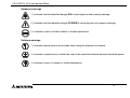
Notes on the Symbols Used in this Manual
At various times throughout this manual certain symbols will be used to highlight points which are intended to
ensure the users personal safety and protect the integrity of equipment. Whenever any of the following
symbols are encountered its associated note must be read and understood. Each of the symbols used will
now be listed with a brief description of its meaning.
ii
FX2N-32CCL CC-Link Interface Block
Hardware warnings
1 ) Indicates that the identified danger WILL cause physical and property damage.
2 ) Indicates that the identified danger POSSIBLY cause physical and property damage.
3 ) Indicates a point of further interest or further explanation.
Software warnings
1 ) Indicates special care must be taken when using this element of software.
2 ) Indicates a special point of which the user of the associate software element should be aware.
3 ) Indicates a point of interest or further explanation.
iii
FX2N-32CCL CC-Link Interface Block
•
Under no circumstances will Mitsubishi Electric be liable responsible for any consequential damage
that may arise as a result of the installation or use of this equipment.
•
All examples and diagrams shown in this manual are intended only as an aid to understanding the
text, not to guarantee operation. Mitsubishi Electric will accept no responsibility for actual use of the
product based on these illustrative examples.
•
Please contact a Mitsubishi Electric distributor for more information concerning applications in life
critical situations or high reliability.
iv
FX2N-32CCL CC-Link Interface Block
Contents
CONTENTS
1. Introduction ................................................................................................1-1
1.1 Outline of product ...................................................................................................... 1-1
1.2 Connection to CC-Link .............................................................................................. 1-3
1.3 System configuration of entire CC-Link ..................................................................... 1-4
2. Product Specifications ...............................................................................2-1
2.1 Outside dimensions and nomenclature ..................................................................... 2-2
2.2 General specifications and performance specifications ............................................ 2-3
3. Connection and Wiring ..............................................................................3-1
3.1 Connection to PC ...................................................................................................... 3-1
3.2 Wiring of power supply .............................................................................................. 3-2
3.3 Wiring of CC-Link ...................................................................................................... 3-4
4. Setting of Remote Device Stations ............................................................4-1
4.1 Setting of station Nos., number of stations and transmission speed ......................... 4-1
4.2 List of number of remote points and remote Nos. ..................................................... 4-3
5. Assignment of Buffer Memory (BFM) .........................................................5-1
5.1 Outline of data communication .................................................................................. 5-1
5.2 BFM dedicated to read .............................................................................................. 5-2
5.3 BFM dedicated to write .............................................................................................. 5-9
5.4 System area of remote I/O ...................................................................................... 5-13
5.5 Contents of errors .................................................................................................... 5-14
v
Contents
FX2N-32CCL CC-Link Interface Block
6. Programming Examples ............................................................................6-1
6.1 System configuration ................................................................................................. 6-1
6.2 Flow of communication data ...................................................................................... 6-3
6.3 Program in master PC ............................................................................................... 6-5
6.4 Program in FX PC ................................................................................................... 6-11
vi
FX2N-32CCL CC-Link Interface Block
1.
Introduction 1
Introduction
The CC-Link interface block FX2N-32CCL is an interface block which connects the FX0N/FX1N/FX2N/FX2NC/
FX3U/FX3UC PLC to the CC-Link.
1.1
Outline of product
Applicable PC
The FX2N-32CCL can be connected as a special extension block of the FX0N/FX1N/FX2N/FX2NC/FX3U/FX3UC
Series PLC.
Control instruction
The buffer memory of the FX2N-32CCL is read and written by FROM/TO instructions.
Connection to CC-Link
The FX2N-32CCL is connected as a remote device station to the CC-Link system.
Shielded twisted pair cables are used for wiring.
Number of I/O points
Eight I/O points (including input and output) are occupied in the FX PC.
However, the capacity of the 5 V DC power supplied from the PC is limited.
The current consumption of 5 V DC in the FX2N-32CCL is 130 mA. Make sure that the total current consumption of 5 V DC including other special blocks does not exceed the criteria.
Station No. and number of stations
Station No.
: 1 to 64 (rotary switch)
Number of stations: 1 to 4 (rotary switch)
1-1
FX2N-32CCL CC-Link Interface Block
Introduction 1
Transmission speed
Transmission distance
10 Mbps
: 100 m
5 Mbps
: 150 m
2.5 Mbps : 200 m
625 kbps : 600 m
156 kbps : 1,200 m
Detailed specifications conform to the CC-Link system common specifications.
Number of remote points
The number of remote I/O points in one station is 32 input points and 32 output points. However, the upper 16
points of the final station are occupied by the CC-Link system as the system area.
The number of remote registers in one station is 4 points of RW write area and 4 points of RW read area.
Because the number of stations can be selected within the range of 1 to 4, the system can be constructed in
accordance with the control size.
1-2
FX2N-32CCL CC-Link Interface Block
1.2
Introduction 1
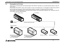
Connection to CC-Link
The FX PC connected with the interface block FX2N-32CCL functions as a remote device station in the CCLink system.
One to four FX2N-32CCL units can be used at a time, and station Nos. not assigned to these FX2N-32CCL
units should be assigned to other remote device stations, remote I/O stations and local stations.
The number of connectable units, the transmission speed, the transmission distance, etc. conform to the CCLink system common specifications.
CC-Link master station
Terminal resistor
Local station
Shielded twisted pair cable
Terminal resistor
Remote device station
FX0N/FX1N/FX2N/FX2NC
/FX3U/FX3UC Series
PLC + FX 2N-32CCL
Remote device station
FX0N/FX1N/FX2N/FX2NC
/FX3U/FX3UC Series
PLC + FX2N-32CCL
Remote I/O station
Remote device station
1-3
FX2N-32CCL CC-Link Interface Block
1.3
Introduction 1
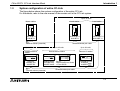
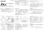
System configuration of entire CC-Link
The figure below shows the system configuration of the entire CC-Link.
For the details, refer to the user manual of the master unit in the CC-Link system.
Up to 26 units
Master station
Local station
A1SJ61BT11
AJ61BT11
A1SJ61BT11
AJ61BT11
Up to 42 units
Remote device station
Intelligent device
station
RS-232C
interface unit
AJ65BT-R2
Analog-digital
converter unit
AJ65BT-64AD
Terminal resistor (essential)
A1SJ61QBT11
AJ61QBT11
Shielded twisted pair cable
Terminal resistor (essential)
Up to 26 units
Local station
FX PC
FX0N/FX2N/FX2NC Series
+ FX2N-32CCL
Up to 64 units
Remote I/O station
Remote I/O unit
AJ65BTB
AJ65BTC
Shielded twisted pair cable
64 units in all
1-4
FX2N-32CCL CC-Link Interface Block
2.
Specifications 2
Product Specifications
Cautions on design
• For the status of each station in the case in which the PC CPU stops its operation or communication error has occurred in the data link, read thoroughly the contents of "5.
Data Link Processing Time" of the user manual of the master unit.
Construct an interlock circuit in a PC program so that the system can operate conservatively using
the communication status information (SB, SW).
If the interlock circuit is not correctly constructed, wrong output or malfunction may occur, and an
accident may occur at the end.
- Receive data from the master station or a local station in which a data link error has occurred
1 ) Remote input (RX), remote output (RY)
The data varies depending on setting of the condition set switch on the unit and setting of the
input data (SW4) in a station in which a data link error has occurred.OFF: Data is cleared (All
OFF).
ON: The data just before an error occurred is held.
2 ) Remote register (RWw, RWr)
The data just before an error occurred is held without regard to setting of the SW4.
•
Never bind the communication cable together with the main circuit, the power cable, etc. Never
locate the communication cable near the main circuit, the power cable, etc.
Keep the communication cable by 100 mm or more from the main circuit, the power cable, etc. If
this distance is not kept, malfunction may occur due to noise.
2-1
FX2N-32CCL CC-Link Interface Block
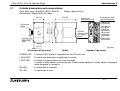
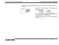
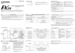
Outside dimensions and nomenclature
Outer paint color: Munsell 0.08GY/7.64/0.81
Accessories: Special block No. label.
Weight: Approx.200 g
87(3.42)
43(1.69)
M3(0.12)
terminal screw
External 24 VDC
ground terminal
Station No.
set switch
FX2N-32CCL
POWER
LRUN
LERR
RD
SD
90(3.54)
Extension
cable
80(3.15)
2.1
Specifications 2
DIN rail
35mm(1.38)
mounting
bezel
2-φ4.5(0.18)
Mounting
hole
Number of
occupied
stations
set switch
Next step
extension
connector
Baud rate
set switch
4(0.16)
[Front face of top cover]
(inches)
[Side]
[Inside of top cover]
POWER LED : Lit when 5 VDC power is supplied from the PC main unit.
L RUN LED
: Lit while communication is performed correctly.
L ERR LED
: Lit when a communication error has occurred.
Lit when a rotary switch is incorrectly set. Flickers when setting of a rotary switch is changed
while the power is turned on.
RD LED
: Lit while data is received.
SD LED
: Lit while data is sent.
2-2
FX2N-32CCL CC-Link Interface Block
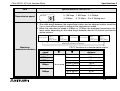
General specifications and performance specifications
General specifications
Dielectric strength:500 VAC for 1 min (between external terminals as a whole and ground terminal) Other
specifications are equivalent to those of the PC basic unit.
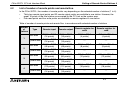
Performance specifications
Specifications of FX2N-32CCL
Item
Drive power supply
24 VDC+/-10%, 50 mA (supplied from external terminal)
Control power supply 5 VDC, 130 mA (supplied from PC via extension cable)
Insulation method
Station type
Network bus and internal power supply are insulated each other by photocoupler.
Remote device station
Station No.: 1 to 64 (set by rotary switch)
STATION
No.
8
7
8
7
3
3
4 5 6
10's digit
1's digit
✕1
0, 65 to 99: Setting error
Number of stations: 1 to 4 (set by rotary switch)
8
7
9 0 1
2
3
OCCUPY
STATION
4 5 6
Number of remote
device points
Number of remote
register points
2
2
✕10
Station No.
Number of stations
9 0 1
9 0 1
4 5 6
2.2
Specifications 2
0: 1 station
1: 2 stations
2: 3 stations
3: 4 stations
4 to 9: Not available
The number of remote I/O points in one station is 32 input points and 32 output points.
However, the upper 16 points are occupied by the CC-Link system as the system area.
The number of remote register points in one station is 4 points of RW write area and 4
points of RW read area.
For the details of the number of remote points and the remote Nos. in accordance with
setting of the number of stations, refer to "4.2 List of number of remote points and
remote Nos."
2-3
FX2N-32CCL CC-Link Interface Block
B RATE
0: 156 kbps 1: 625 kbps 2: 2.5 Mbps
3: 5 Mbps
4: 10 Mbps 5 to 9: Setting error
8
9 0 1
2
3
Transmission speed
Specifications of FX2N-32CCL
156 kbps, 625 kbps, 2.5 Mbps, 5 Mbps, 10 Mbps (set by rotary switch)
7
Item
Specifications 2
4 5 6
It varies depending on the transmission speed.
1 )The cable length between the master/local station and an adjacent station should be
2 m or more without regard to setting of the transmission speed.
2 )When the transmission speed is 5 Mbps or 10 Mbps, the maximum transmission distance varies depending on the cable length between remote I/O stations and remote
device stations.
R e m o te I/O
sta tio n
R e m o te
d e vice sta tio n
M a s te r s ta tio n
①
Maximum
transmission distance
R e m o te I/O
sta tio n
R e m o te
d e vice sta tio n
②
L o ca l sta tio n
L o ca l sta tio n
①
①
M axim um transm ission distance
R e m o te I/O
sta tio n
R e m o te
d e vice sta tio n
R e m o te I/O
sta tio n
R e m o te
d e vice sta tio n
②
FX PC functions as a remote device station.
Transmission
speed
156kbps
625kbps
2.5Mbps
5Mbps
10Mbps
c
d
30 cm or more
30 cm or more
30 cm or more
60 cm or more
2 m or more
30 to 59 cm
1 m or more
60 to 99 cm
30 to 59 cm
Maximum transmission
distance
1200 m
600 m
200 m
150 m
110 m
100 m
80 m
50 m
2-4
FX2N-32CCL CC-Link Interface Block
Item
Specifications 2
Specifications of FX2N-32CCL
Operation indication
LEDs (POWER, L RUN, L ERR, RD, SD)
Number of occupied
I/O points
Eight I/O points (including input and output) of FX PLC
Applicable PC
Communication with
PC
FX0N/FX1N/FX2N/FX2NC/FX3U/FX3UC Series PLC
Communication is performed from the FX PLC via the buffer memory using FROM/TO
instructions.
2-5
FX2N-32CCL CC-Link Interface Block
Specifications 2
Memo
2-6
FX2N-32CCL CC-Link Interface Block
Connection and Wiring 3
3.
Connection and Wiring
3.1
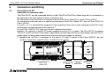
Connection to PC
Connection of extension cable
The FX2N-32CCL can be connected directly to the FX0N/FX1N/FX2N/FX3U Series main unit or connected on
the right side of an other extension block or extension unit.
For connection to the main unit or an extension block of the FX2NC Series PLC, use an FX2NC-CNV-IF.
For connection to the main unit or a special function block of the FX3UC Series PLC, use an FX2NC-CNV-IF or
FX3UC-1PS-5V.
A unit No. 0 to 7 is automatically assigned to each special function unit or block connected to the PLC main
unit starting from the one nearest the main unit.*1
For the FX3UC-32MT-LT PLC main unit, the unit numbers start at No.1.
However, the capacity of the 5V DC power supplied from the PLC is limited. The FX2N-32CCL consumes
130mA of current from the 5V DC power supply. Make sure that the total current consumption from the 5V DC
power supply including other special function blocks does not exceed the capacity.
*1 Because the unit No.0 is assigned to the built-in CC-Link/LT master in the FX3UC-32MT-LT, the unit
numbers assigned to special function units/blocks start at No.1.
L
COM X0
X2
24+
X1
N
X4
X5
X6
X7
X10
IN
IN 0
1
2
3
4
5
6
7
X14
X16
X20
X22
X24
X13
X15
X17
X21
X23
X25
0 1 2 3 4 5 6 7 20 21 22 23 24 25 26 27
POWER
FX2N-32CCL
10 11 12 13 14 15 16 17
FX2N-32CCL
POWER
POWER
RUN
BATT.V
LRUN
LERR
RD
POWER
SD
LRUN
LERR
RD
SD
PROG.E
FX2N-48MR
Y0
COM1
Y2
Y3
Y4
Y6
COM2 Y5
Y7
Y10
COM3
OUT
0 1 2 3 4 5 6 7 20 21 22 23 24 25 26 27
10 11 12 13 14 15 16 17
Y13
Y14
COM4 Y15
FX2N -48MR-ES/UL
X000~X027
Y000~Y027
Y20
Y22
Y24
Y26 COM5
Y21
Y23
Y25
Y27
CPU.E
FX2N-16EX
IN 0
1
2
3
4
5
6
7
FX2N-32CCL FX2N-16EX
special function -ES/UL
block
X030~X047
No.0
FX2N-32CCL
special function
block
No.1
3-1
FX2N-32CCL CC-Link Interface Block
3.2
Connection and Wiring 3
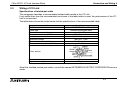
Wiring of power supply
Wiring
Service power
supply for sensor
Grounding resistor
100 Ω or less
(class D)
COM
24+
24+
24-
PC main unit
FX2N-32CCL
24 VDC+/-10%,
50 mA
24 VDC service power
supply for PLC can be
used instead.
Extension cable
Handling of crimp-style terminal
•
•
•
Use crimp-style terminals of the dimensions shown as follows.
The terminal tightening torque should be 0.5 to 0.8 Nym.
Tighten terminals securely so that malfunction will not occur.
Handle the crimp terminal of the following size when 1 wire is used per terminal.
6.2 mm (0.24" )
or less
φ 3.2 (0.13")
Terminal
screw
Crimp
terminal
φ 3.2 (0.13")
6.2 mm (0.24")
or less
Terminal
3-2
FX2N-32CCL CC-Link Interface Block
•
Connection and Wiring 3
Handle the crimp terminal of the following size when 2 wires are used per terminal.
6.2 mm (0.24" )
or less
φ 3.2 (0.13")
Terminal
screw
Crimp
terminal
6.3 mm or more
6.2 mm (0.24")
or less
φ 3.2 (0.13")
Terminal
6.3 mm or more
3-3
FX2N-32CCL CC-Link Interface Block
3.3
Connection and Wiring 3
Wiring of CC-Link
Specifications of twisted pair cable
This paragraph describes a recommended twisted cable usable in the CC-Link.
If any cable other than the recommended one shown in the table below is used, the performance of the CCLink is not assured.
The table below shows the model name and the specifications of the recommended cable.
Item
Model name
Cable type
Conductor cross sectional area
Conductor resistance (20°C)
Insulation resistance
Withstand voltage
Electrostatic capacity (kHz)
Characteristic impedance (1 MHz)
Specifications
FANC-SB 0.5mm2✕3
Shielded twisted pair cable
0.5mm2
37.8 Ω/km or less
10,000 MΩ-km or more
500 VDC, 1 min
60 nF/km or less
100±15Ω
Blue
DA
White
Cross section
DB
Yellow
Outside dimensions
Approximate weight
Sheath
Shield
Aluminum
tape
DG
Ground cable
7mm
65kg/km
About the shielded twisted pair cables, consult the nearest MITSUBISHI ELECTRIC CORPORATION service
center.
3-4
FX2N-32CCL CC-Link Interface Block
Connection and Wiring 3
Wiring of twisted pair cable
Wire the FX2N-32CCL and the CC-Link using shielded twisted pair cables as shown in the figure below.
Master
unit
Terminal
resistor
FX2N-32CCL
DA
DB
DG
SLD
FG
Class D
grounding
•
•
•
•
•
•
Shielded twisted
pair cable
Remote I/O
unit
DA
DA
DB
DB
DG
DG
SLD
SLD
FG
FG
Class D
grounding
DA
DB
Terminal
resistor
Class D
grounding
Connect the terminals DA and DA, DB and DB as well as DG and DG of each station with shielded
twisted pair cables. Because two DA terminals and two DB terminals are provided in the FX2N-32CCL,
a next station can be easily connected.
Connect the SLD terminal of each station to a shield of a shielded twisted pair cable.
Perform Class D grounding to the FG terminal of each station.
Wiring of each station can be performed from any point without regard to the station No.
When the FX2N-32CCL is used as the terminal station, connect a terminal resistor between the terminals
DA and DB of the FX2N-32CCL. The terminal resistor is packed together with the Master unit.
The maximum transmission distance and the distance between stations in the CC-Link system vary
depending on the selected transmission speed. For the details, refer to the maximum transmission distance described in "2.2 General specifications and performance specifications" or the specifications
described in the manual of the CC-Link master unit.
3-5
FX2N-32CCL CC-Link Interface Block
Setting of Remote Device Stations 4
4.
Setting of Remote Device Stations
4.1
Setting of station Nos., number of stations and transmission speed
Setting the rotary switch
The station No., the number of stations and the transmission speed can be set using rotary switches provided
inside the panel cover of the FX2N-32CCL.
Setting of each rotary switch becomes valid when the power of the FX PC is turned on.
Set each rotary switch while the power of the PC is turned off. If setting of a rotary switch (except the rotary
switch for the number of stations) is changed while the power of the PC is turned on, the L ERR LED is lit.
8
7
8
7
8
7
8
7
4 5 6
4 5 6
1's digit
2 ) Number of stations: 1 to 4
4 5 6
4 5 6
8
7
4 5 6
8
9 0 1
2
7
8
3
3
4 5 6
3)Baud rate
set switch
OCCUPY
STATION
4 5 6
7
9 0 1
2
0 156K
1 625K
2 2.5M
3 5M
4 10M
10's digit
3
POWER
B RATE
x1
3
9 0 1
✕1
Set the station No. within the range of 1 to 64.
One to four FX2N-32CCL units can be used at a
time. Pay attention so that the station
No. set here is not assigned to an other unit.
0, 65 to 99: Setting error
2
1st.
2st.
3st.
4st.
3
3
0
1
2
3
2
2
x10
OCCUPY
STATION
✕10
9 0 1
9 0 1
9 0 1
2
9 0 1
STATION
No.
3
32CCL
STATION
NO.
1 ) Station No.: 1 to 64
2
1)Station No.
set switch
2)Number of
occupied stations
set switch
Numerics 1 to 3 correspond to 1 to 4 stations
respectively.
0: 1 station
3: 4 stations
1: 2 stations
4 to 9: Not available
2: 3 stations
The number of remote device points is determined by the number of stations set here.
(☞ 4.2)
4-1
FX2N-32CCL CC-Link Interface Block
Setting of Remote Device Stations 4
3 ) Baud rate (transmission speed): 156 kbps, 625 kbps, 2.5 Mbps, 5 Mbps, 10
Mbps
B RATE
8
2
7
9 0 1
3
Numerics 0 to 4 correspond to 156 kbps to10
Mbps respectively.
0: 156 kbps
3: 5 Mbps
1: 625 kbps
4: 10 Mbps
2: 2.5 Mbps
5 to 9: Setting error
Set the transmission speed in accordance with
the specifications of the maximum
transmission distance and the transmission
speed. (☞ 2.2)
4-2
4 5 6
FX2N-32CCL CC-Link Interface Block
4.2
Setting of Remote Device Stations 4
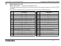
List of number of remote points and remote Nos.
In the FX2N-32CCL, the number of remote points vary depending on the selected number of stations (1 to 4).
•
•
Thirty-two remote input points and 32 remote output points are available in one station. However, the
upper 16 points of the final station are occupied by the CC-Link as the system area.
Four read points and four write points are available as remote registers in one station.
Table of number of remote points and remote Nos. in accordance with selected number of stations
Number
of
stations
Remote input
Remote output
Remote register for
write
Remote register for
read
User area
RX00 to RX0F
(16 points)
RY00 to RY0F
(16 points)
RWr0 to RWr3
(4 points)
RWw0 to RWw3
(4 points)
System area
RX10 to RX1F
(16 points)
RY10 to RY1F
(16 points)
⎯
⎯
User area
RX00 to RX2F
(48 points)
RY00 to RY2F
(48 points)
RWr0 to RWr7
(8 points)
RWw0 to RWw7
(8 points)
System area
RX30 to RX3F
(16 points)
RY30 to RY3F
(16 points)
⎯
⎯
User area
RX00 to RX4F
(80 points)
RY00 to RY4F
(80 points)
RWr0 to RWrB
(12 points)
RWw0 to RWwB
(12 points)
System area
RX50 to RX5F
(16 points)
RY50 to RY5F
(16 points)
⎯
⎯
User area
RX00 to RX6F
(112 points)
RY00 to RY6F
(112 points)
RWr0 to RWrF
(16 points)
RWw0 to RWwF
(16 points)
System area
RX70 to RX7F
(16 points)
RY70 to RY7F
(16 points)
⎯
⎯
Type
1
2
3
4
4-3
FX2N-32CCL CC-Link Interface Block
Assignment of Buffer Memory (BFM) 5
5.
Assignment of Buffer Memory (BFM)
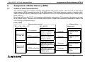
5.1
Outline of data communication
The interface block FX2N-32CCL transfers data between the master station in the CC-Link via the built-in
buffer memory (BFM) backed up by the 16-bit RAM memory. This buffer memory consists of memory dedicated to write and memory dedicated to read. Numbers of #0 to #31 are assigned respectively to each type of
buffer memory.
By writing data from the FX PC to the memory dedicated to write using a TO instruction, the data can be sent
to the master station. The data sent from the master station is read from the memory dedicated to read to the
FX PC using a FROM instruction.
Flow of data
Remote device station
FX0N, FX2N, FX2NC PC
TO instruction
Internal relay,
I/O relay, etc.
FROM instruction
Master station
FX2N-32CCL
Buffer memory for I/O
Dedicated to write
BFM #0 to BFM #7
(RX00 to RX7F)
Dedicated to read
BFM #0 to BFM #7
(RY00 to RY7F)
Master unit
Link scan
Remote input
(RX)
Link scan
Remote output
(RY)
Link scan
Remote register
(RWr)
Link scan
Remote register
(RWw)
Buffer memory for data
TO instruction
Data (word)
device, etc.
FROM instruction
Dedicated to write
BFM #8 to BFM #23
(RWr0 to F)
Dedicated to read
BFM #8 to BFM #23
(RWw0 to F)
5-1
FX2N-32CCL CC-Link Interface Block
5.2
Assignment of Buffer Memory (BFM) 5
BFM dedicated to read
Master station → FX
Buffer memory dedicated to read
In this buffer memory, data written from the master station and the system information on the FX2N-32CCL
are saved.
The contents of the buffer memory can be read from the FX PC using FROM instructions.
BFM
No.
#0
#1
#2
#3
#4
#5
#6
#7
#8
#9
#10
#11
#12
#13
#14
#15
Description
Remote output RY00 to RY0F (set station)
Remote output RY10 to RY1F (set station)
Remote output RY20 to RY2F (set station + 1)
Remote output RY30 to RY3F (set station + 1)
Remote output RY40 to RY4F (set station + 2)
Remote output RY50 to RY5F (set station + 2)
Remote output RY60 to RY6F (set station + 3)
Remote output RY70 to RY7F (set station + 3)
Remote register RWw 0 (set station)
Remote register RWw 1 (set station)
Remote register RWw 2 (set station)
Remote register RWw 3 (set station)
Remote register RWw 4 (set station+ 1)
Remote register RWw 5 (set station+ 1)
Remote register RWw 6 (set station+ 1)
Remote register RWw 7 (set station+ 1)
BFM
No.
#16
#17
#18
#19
#20
#21
#22
#23
#24
#25
#26
#27
#28
#29
#30
#31
Description
Remote register RWw 8 (set station+ 2)
Remote register RWw 9 (set station+ 2)
Remote register RWw A (set station+ 2)
Remote register RWw B (set station+ 2)
Remote register RWw C (set station+ 3)
Remote register RWw D (set station+ 3)
Remote register RWw E (set station+ 3)
Remote register RWw F (set station+ 3)
Set value of baud rate
Communication status
CC-Link model code
Set value of its own station No.
Set value of number of occupied stations
Error code
FX Series model code (K7040)
Not available
5-2
FX2N-32CCL CC-Link Interface Block
Assignment of Buffer Memory (BFM) 5
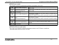
Details of buffer memory
[BFM #0 to #7 (remote output RY00 to RY7F)]
•
•
Sixteen remote output points RYF to RY0 are assigned for b15 to b0 of each buffer memory consisting of 16 bits.
The ON/OFF status information shown by each bit indicates the contents of the remote output written
from the master unit to the FX2N-32CCL.
The FX PC reads this information to bit devices and word devices of the PC using FROM instructions.
In the FX2N-32CCL, the remote output point range (RY00 to RY7F) varies depending on the selected
number of stations (1 to 4).
The upper 16 points in the final station are occupied by the CC-Link system as the system area, so cannot be used as the user area. (☞ 4.2)
Example in which the ON/OFF status of BFM #0 b0 to b15 is read to the auxiliary relay in the FX PC
Read by FROM instruction (BFM #0 → M15 to M0)
FNC78
K0
K0
K4M0
K1
FROM
Use
example
Block No. Transfer Transfer Number of
source destina- transfer
(BFM #0) tion (M15 points
to M0)
(BFM #0, 1
point)
b15
b0
RYRYRYRYRYRYRYRYRYRYRYRYRYRYRYRY
0 F 0 E 0 D 0 C 0 B 0 A 0 9 0 8 0 7 0 6 0 5 0 4 0 3 0 2 0 1 0 0 B F M #0
FR O M instruction
M M M M M M M M M M M M M M M M
15 14 13 12 11 10 9 8 7 6 5 4 3 2 1 0
P C auxiliary
relay
M0(RY00)
M1(RY01)
~
Drive circuit
M15(RY0F)
5-3
FX2N-32CCL CC-Link Interface Block
Assignment of Buffer Memory (BFM) 5
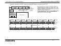
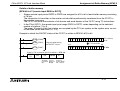
Example in which the ON/OFF status of multiple BFM points are read to the FX PC
FNC78
FROM
K0
K0
K4M0
•
K
Number of
Block No. Transfer Transfer Number of transfer points
source destinat- transfer
(1 to 8) is
specified.
(BFM #0) ion (M*** points
to M0)
Use
example
M0(RY00)
•
By changing the number of transfer points of
FROM instruction within the range of K1 to K8,
BFM #0 to BFM #7 can be read at a time to the
auxiliary relay in the FX PC.
When the output relays (Y) are specified as the
transfer destination, they are processed by
octal (Y7 to Y0) at a time.
M1(RY01)
Drive circuit
~
M
(RY
)
B F M #7
B F M #6
B F M #5
B F M #4
B F M #3
B F M #2
B F M #1
B F M #0
b0 b15
b15
b0 b15
b0 b15
b0 b15
b0 b15
b0 b15
b0 b15
b0
B F M .N o.
RYRY
7F 7E
N um ber of
transfer
points
RYRYRYRY
71 70 6F 6E
K8
RYRYRYRY
61 60 5F 5E
K7
RYRYRYRY
51 50 4F 4E
K6
K5
RYRYRYRY
41 40 3F 3E
RYRYRYRY
31 30 2F 2E
K4
RYRYRYRY
21 20 1F 1E
K3
RYRYRYRY
11 10 0F 0E
K2
RYRY
01 00
K1
F R O M instruction
M M
M M M M
1 27 1 26
1 13 1 12 1 11 1 10
M M M M
97 96 95 94
M M M M
81 80 79 78
M M M M
65 64 63 62
M M M M
49 48 47 46
M M M M
33 32 31 30
M M M M
17 16 15 14
M M
1 0
5-4
FX PC
auxiliary
relay
FX2N-32CCL CC-Link Interface Block
Assignment of Buffer Memory (BFM) 5
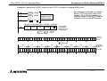
[BFM #8 to #23 (remote register RWw0 to RWwF)]
•
•
To each buffer memory No., a remote register No. RWw0 to RWwF is assigned.
The information saved in the buffer memory indicates the contents of the remote register written from the
master unit to the FX2N-32CCL.
The FX PC can read this information to the word device and the bit device in the PC using FROM instructions.
In the FX2N-32CCL, the remote register range (RWw0 to RWwF) varies depending on the selected number of stations (1 to 4). (☞ 4.2)
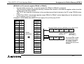
Example in which BFM #8 to BFM #23 are read to D0 to D15 in the FX PC
BFM
No.
#8
#9
#10
#11
#12
#13
#14
#15
#16
#17
#18
#19
#20
#21
#22
#23
RWw
No.
0
1
2
3
4
5
6
7
8
9
A
B
C
D
E
F
FROM
instruction
PC data
register
D0
D1
D2
D3
D4
D5
D6
D7
D8
D9
D10
D11
D12
D13
D14
D15
Read by FROM instruction (BFM #8 to #23→D0 to D15)
FNC78
K0
K8
D0
K16
FROM
Use
example
Block No. Transfer Transfer Number of
source destinat- transfer points
(BFM #8) ion
(BFM #8 to
#23, 16 points)
FNC12
MOV
D0
(RWw0)
D50
By changing the number
of transfer points within
the range of K1 to K16,
the number of BFM
points to be read can be
changed.
5-5
FX2N-32CCL CC-Link Interface Block
Assignment of Buffer Memory (BFM) 5
[BFM #24 (set value of baud rate)]
The setting of the baud rate (transmission speed) set switch provided in the FX2N -32CCL is saved as a
numeric of 0 to 4.
The saved value is determined when the power of the FX PC is turned on. If the setting is changed while the
power is turned on, the changed setting becomes valid when the power is turned on at the next time.
0: 156 kbps
1: 625 kbps
2: 2.5 Mbps
3: 5 Mbps
4: 10 Mbps
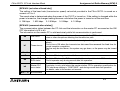
[BFM #25 (communication status)]
The communication status between the CC-Link and the information on the master PC are saved as the ON/
OFF information to b15 to b0.
The information on the master PC is valid exclusively while link communication is performed.
CRC error
This bit turns ON when there is a discrepancy with the CRC value due to unwanted
noise or other disruptions affecting the transmission path.
b1
Timeout error
This error occurs when the next refresh is not given during the execution of a current
refresh.
This bit turns ON when the transmission data send time exceeds the fixed time for
normal reception completion.
The line may be shut down, the system may go down, or the power may be turned
OFF.
b2 ~ 6
Not available
-
b0
b7
Link execution
This bit is ON during data link with the master station.
b8
Master PLC
RUN status
This bit is ON when the PLC connected to the master station is in RUN mode.
This bit operates only during normal data link operation.
b9
Master PLC
error status
This bit turns ON when the PLC connected to the master station has an error.
The status is only valid when the master station CPU's operation specification for
CPU shut down setting is "CONTINUE", and during normal data link operation.
For details, refer to the master unit manual.
b10 ~ 15
Not available
-
5-6
FX2N-32CCL CC-Link Interface Block
Assignment of Buffer Memory (BFM) 5
[BFM #26 (CC-Link model code)]
The model code is saved in the following format.
01
01
H
Recognition code in
CC-Link system
Version No. of system software in the
FX2N-32CCL
[Set value of BFM #27 (its own station No.)]
The setting of the station No. set switch provided in the FX2N-32CCL is saved as a numeric of 1 to 64.
The saved value is determined when the power of the FX PC is turned on. If the setting is changed while the
power is turned on, the changed setting becomes valid when the power is turned on at the next time.
[BFM #28 (set value of number of occupied stations)]
The setting of the number of occupied stations set switch provided in the FX2N-32CCL is saved as a numeric
of 0 to 3.
0: 1 station 1: 2 stations 2: 3 stations 3: 4 stations
5-7
FX2N-32CCL CC-Link Interface Block
Assignment of Buffer Memory (BFM) 5
[BFM #29 (error code)]
The contents of an error are saved as the ON/OFF information to b15 to b0.
This bit turns ON when the rotary switch is set outside the allowable
setting range.
b0
Station number setting error
b1
Transmission rate setting error This bit turns ON when the rotary switch is set outside the allowable
(Band rate setting error)
setting range.
b2 ~ 3
Not available
-
b4
Station number change error
This bit turns ON when the rotary switch setting is changed after the
FX2N-32CCL is started.
It turns OFF when the rotary switch is returned to its previous setting.
b5
Transmission rate change
error
(Band rate change error)
This bit turns ON when the rotary switch setting is changed after the
FX2N-32CCL is started.
It turns OFF when the rotary switch is returned to its previous setting.
b6 ~ 7
b8
b9 ~ 15
Not available
External 24 V power failure.
Not available
This bit turns ON when the external power supply 24V DC is not
supplied.
-
[BFM #30 (FX Series model code)]
The model code assigned to each special extension device in the FX Series is saved here.
The model code of the FX2N-32CCL is K7040.
5-8
FX2N-32CCL CC-Link Interface Block
5.3
Assignment of Buffer Memory (BFM) 5
BFM dedicated to write
FX → master station
Buffer memory dedicated to write
In this buffer memory, the contents written from the FX PC to the master station are saved.
The FX PC writes the contents of bit devices and data (word) devices of the PC using TO instructions.
BFM
No.
#0
#1
#2
#3
#4
#5
#6
#7
#8
#9
#10
#11
#12
#13
#14
#15
Description
Remote input RX00 to RX0F (set station)
Remote input RX10 to RX1F (set station)
Remote input RX20 to RX2F (set station + 1)
Remote input RX30 to RX3F (set station + 1)
Remote input RX40 to RX4F (set station + 2)
Remote input RX50 to RX5F (set station + 2)
Remote input RX60 to RX6F (set station + 3)
Remote input RX70 to RX7F (set station + 3)
Remote register RWr 0 (set station)
Remote register RWr 1 (set station)
Remote register RWr 2 (set station)
Remote register RWr 3 (set station)
Remote register RWr 4 (set station + 1)
Remote register RWr 5 (set station + 1)
Remote register RWr 6 (set station + 1)
Remote register RWr 7 (set station + 1)
BFM
No.
#16
#17
#18
#19
#20
#21
#22
#23
#24
#25
#26
#27
#28
#29
#30
#31
Description
Remote register RWr 8 (set station + 2)
Remote register RWr 9 (set station + 2)
Remote register RWr A (set station + 2)
Remote register RWr B (set station + 2)
Remote register RWr C (set station + 3)
Remote register RWr D (set station + 3)
Remote register RWr E (set station + 3)
Remote register RWr F (set station + 3)
Undefined (Write is disabled.)
Undefined (Write is disabled.)
Undefined (Write is disabled.)
Undefined (Write is disabled.)
Undefined (Write is disabled.)
Undefined (Write is disabled.)
Undefined (Write is disabled.)
Not available
5-9
FX2N-32CCL CC-Link Interface Block
Assignment of Buffer Memory (BFM) 5
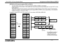
Details of buffer memory
[BFM #0 to #7 (remote input RX00 to RX7F)]
•
•
Sixteen remote input points RXF to RX0 are assigned for b15 to b0 of each buffer memory consisting
of 16 bits.
The information to be written to the master unit should be preliminarily transferred from the FX PC to
these buffer memories.
The FX PC can write the contents of bit devices and word devices of the FX PC using TO instructions.
In the FX2N-32CCL, the remote input point range (RX00 to RX7F) varies depending on the selected
number of stations (1 to 4).
The upper 16 points of the final station are occupied by the CC-Link system as the system area, so cannot be used as the user area. (☞ 4.2)
Example in which the ON/OFF status of the FX PC is written to BFM #0 b15 to b0
M M M M M M M M M M M M M M M M
M 100 (R X 00)
M 101 (R X 01)
1 15 1 14 1 13 1 12 1 11 1 10 1 09 1 08 1 07 1 06 1 05 1 04 1 03 1 02 1 01 1 00
~
P rogram determ ining
the O N /O F F status
b15
T O instruction
P C auxiliary
relay
b0
RXRXRXRXRXRXRXRXRXRXRXRXRXRXRXRX
0 F 0 E 0 D 0 C 0 B 0 A 0 9 0 8 0 7 0 6 0 5 0 4 0 3 0 2 0 1 0 0 B F M #0
M 115 (R X 0F )
W rite by T O instruction (M 115 to M 100 → B F M #0)
F N C 79
K0
K0
K 4M 100
K1
TO
B lo ck N o . T ra n s fe r
d e stin a tio n (B F M
#0)
T ra n s fe r
s o u rc e
(M 1 1 5 to
M 100)
Num ber of
tra n s fe r
p o in ts (B F M
# 0 , 1 p o in t)
5-10
FX2N-32CCL CC-Link Interface Block
Assignment of Buffer Memory (BFM) 5
Example in which the ON/OFF status of the FX PC is written to multiple BFM points
(RX00)
M101
(RX01)
M
(RX F)
•
By changing the number of transfer
points of TO instruction within the
range of K1 to K8, the contents of
auxiliary relays in the FX PC can be
written to two or more BFM points.
Program
determining the
ON/OFF status
~
M100
Write by TO instruction (M*** to M100 → BFM #0)
The number
FNC79
K0
K0
K4M100
K
of transfer
TO
points (1 to 8)
Block No. Transfer Transfer Number of
is specified.
destinat- source transfer
ion
(M*** to points
(BFM #0) M100)
M M
M M M M
M M M M
M M M M
M M M M
M M M M
M M M M
M M M M
M M
2 27 2 26
2 13 2 12 2 11 2 10
1 97 1 96 1 95 1 94
1 81 1 80 1 79 1 78
1 65 1 64 1 63 1 62
1 49 1 48 1 47 1 46
1 33 1 32 1 31 1 30
1 17 1 16 1 15 1 14
1 01 1 00
K8
K7
b15
RXRX
7F 7E
K6
b0 b15
RXRXRXRX
71 70 6F 6E
B F M #7
K5
b0 b15
RXRXRXRX
61 60 5F 5E
B F M #6
TO
instruction
K4
K3
b0 b15
b0 b15
b0 b15
RXRXRXRX
51 50 4F 4E
B F M #5
RXRXRXRX
41 40 3F 3E
B F M #4
RXRXRXRX
31 30 2F 2E
B F M #3
K2
RXRXRXRX
21 20 1F 1E
B F M #2
N um ber
of transfer
b0 points
K1
b0 b15
b0 b15
RXRXRXRX
11 10 0F 0E
B F M #1
FX PC
auxiliary
relay
R X R X B F M .N o
01 00 .
B F M #0
5-11
FX2N-32CCL CC-Link Interface Block
Assignment of Buffer Memory (BFM) 5
[BFM #8 to #23 (remote register RWr0 to RWrF)]
•
•
To each buffer memory No., a remote register No. RWr0 to RWrF is assigned.
The information to be written to the master unit should be preliminarily transferred from the FX PC to this
buffer memory.
The FX PC can write the contents of word devices and bit devices of the FX PC using TO instructions.
In the FX2N-32CCL, the remote register point range (RWr0 to RWrF) varies depending on the selected
number of stations (1 to 4). (☞ 4.2)
Example in which D100 to D115 in the FX PC are written to BFM #8 to BFM #23
TO
instruction
BFM
No.
#8
#9
#10
#11
#12
#13
#14
#15
#16
#17
#18
#19
#20
#21
#22
#23
RWw
No.
0
1
2
3
4
5
6
7
8
9
A
B
C
D
E
F
FNC12
MOV
K20
D100
(RWr0)
FNC12
MOV
K35
D101
(RWr1)
FNC12
MOV
K55
D115
(RWrF)
~
PC data
register
D100
D101
D102
D103
D104
D105
D106
D107
D108
D109
D110
D111
D112
D113
D114
D115
Program
determining the
ON/OFF status
Write by TO instruction (D115 to D100 → BFM #8)
FNC79
K0
K8
D100
K16
TO
Block No. Transfer Transfer Number of transfer
destinat- source points (BFM #8 to
ion
BFM #23, 16 points)
(BFM #8)
By changing the number of
transfer points within the
range of K1 to K16, the
number of BFM points to
be written can be changed.
5-12
FX2N-32CCL CC-Link Interface Block
5.4
Assignment of Buffer Memory (BFM) 5
System area of remote I/O
As to the number of remote I/O points (RX00 to RX7F/RY00 to RY7F) in the FX2N-32CCL, the range and the
number of points vary depending on the selected number of stations (1 to 4).
The upper 16 points of the final station are occupied by the CC-Link system as the system area, so cannot be
used as the user area. (☞ 4.2) The tables below show assignment of the system area.
Master station → FX
Device No.
RY(2n-1)0
RY(2n-1)1
RY(2n-1)2
RY(2n-1)3
RY(2n-1)4
RY(2n-1)5
RY(2n-1)6
RY(2n-1)7
RY(2n-1)8
RY(2n-1)9
RY(2n-1)A
RY(2n-1)B
RY(2n-1)C
RY(2n-1)D
RY(2n-1)E
RY(2n-1)F
Dedicated to read
Description
Unusable
Unusable
Unusable
Unusable
Unusable
Unusable
Unusable
Unusable
Initial data processing completion flag
Initial data processing request flag
Error reset request flag
Undefined
Reserved (unusable)
Reserved (unusable)
Reserved (unusable)
Reserved (unusable)
FX → Master station
Device No.
RX(2n-1)0
RX(2n-1)1
RX(2n-1)2
RX(2n-1)3
RX(2n-1)4
RX(2n-1)5
RX(2n-1)6
RX(2n-1)7
RX(2n-1)8
RX(2n-1)9
RX(2n-1)A
RX(2n-1)B
RX(2n-1)C
RX(2n-1)D
RX(2n-1)E
RX(2n-1)F
Dedicated to write
Description
Unusable
Unusable
Unusable
Unusable
Unusable
Unusable
Unusable
Unusable
Initial data processing request flag
Initial data processing completion flag
Error status flag
Remote ready
Reserved (unusable)
Reserved (unusable)
Reserved (unusable)
Reserved (unusable)
"n" indicates the number of occupied stations.
(Example: When three stations are occupied, the device Nos. are "RY50 to RY5F" and "RX50 to RX5F".)
5-13
FX2N-32CCL CC-Link Interface Block
5.5
Assignment of Buffer Memory (BFM) 5
Contents of errors
The table below shows the contents of errors indicated by LEDs provided in the FX2N-32CCL.
The causes of an error can be detected based on the contents of the error saved in the buffer memory dedicated to read BFM #29 and the status of the LED. (☞ 5.2)
For errors related to the PC and the master unit, refer to the user’s manual (detailed manuals) of the PC and
the master unit.
L RUN
Lit z
L ERR
Causes of error
Extinguished { Data link is in the normal status.
The following causes are estimated.
For details, refer to the user’s manual (detailed manual) of the master unit.
•
•
Extinguished { Extinguished { •
•
•
•
•
Extinguished { Lit z
Extinguished { Flickers
A cable is disconnected.
(L ERR LED is extinguished on units after the unit in which disconnection
has occurred.)
A cable is short-circuited.
(L RUN LED is extinguished on all the units.)
Link of the master station is stopped.
(L RUN LED is extinguished on all the units except the master station.)
Power supplied to the FX2N-32CCL is turned off.
(ERR LED is extinguished on the master station and the local stations.)
Same station No. is assigned to the FX2N-32CCL and an other station.
(L RUN LED is extinguished on the unit to which the same station No. is
assigned.)
The transmission speed is incorrectly set.
The FX2N-32CCL is not set to a parameter.
The unit is started up while the station No. set switch is set to an unallowable
value.
Setting of the station No. set switch or the transmission speed set switch is
changed during data linking.
5-14
FX2N-32CCL CC-Link Interface Block
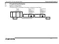
Programming Examples 6
6.
Programming Examples
6.1
System configuration
A sample program is explained in the system configuration shown below.
Master
station
(station No. 0)
Remote device
station
(station No. 1)
Occupation of
four stations is
specified.
A62P A3NCPU AJ61BT11 AY41
X/Y 00
~
~
Terminal
resistor
Y20
X/Y 1F
Y2F
FX PC
FX2N-32CCL
A
Shielded twisted pair cable
Remote device
station
(station No. 5)
Occupation of
two stations is
specified.
FX PC
FX2N-32CCL
B
Terminal
resistor
6-1
FX2N-32CCL CC-Link Interface Block
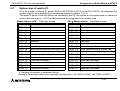
Programming Examples 6
Preparation
1 ) Set the station No. set switch, the mode set switch, the transmission set switch and the condition set
switch provided on the master unit. (☞ User’s manual of master unit)
2 ) Set the station No. set switch, the number of occupied stations set switch and the transmission speed set
switch provided on the FX2N-32CCL. (☞ 4.1)
Item
Setting of FX2N-32CCL (station No. 1)
Setting of FX2N-32CCL (station No. 5)
Station No.
1 (rotary switch)
5 (rotary switch)
Number of
occupied
stations
4 (rotary switch)
2 (rotary switch)
Transmission
speed
In accordance with setting in master unit (rotary switch)
Assignment of Number of remote points and No. when four
number of
stations are occupied
remote points •Remote input:
and No.
RX00 to RX6F (112 points) for user area
RX70 to RX7F (16 points) for system area
Number of
•Remote
output:
points and No.
RY00 to RY6F (112 points) for user area
are deterRY70 to RY7F (16 points) for system area
mined by
selected num- •Remote register:
RWr0 to RWrF (16 points) for write
ber of occuRWw0 to RWwF(16 points) for read
pied stations.
Number of remote points and No. when two
stations are occupied
•Remote input:
RX00 to RX2F (48 points) for user area
RX30 to RX3F (16 points) for system area
•Remote output:
RY00 to RY2F (48 points) for user area
RY30 to RY3F (16 points) for system area
•Remote register:
RWr0 to RWr7 (8 points) for write
RWw0 to RWw7 (8 points) for read
6-2
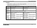
FX2N-32CCL CC-Link Interface Block
6.2
Programming Examples 6
Flow of communication data
Remote input (RX), remote output (RY)
In a sample program, communication is performed between remote inputs and remote outputs as shown in
the figure below.
Master station
(station No. 0)
Master PC
Remote input
(RX)
E0H
~
FROM
E7H
E8H
BFM#0(RX0F~RX00)
RX7F~RX70
BFM#7(RX7F~RX70)
RX8F~RX80
Remote output (RY)
~
M963~M900
FROM
Remote input (RX)
~
M627~M500
RX0F~RX00
Remote device station (station No. 1)
FX2N-32CCL A
FX PC
BFM#0(RY0F~RY00) FROM
~
EBH RXBF~RXB0
TO
M227~M100
M427~M300
BFM#7(RY7F~RY70)
Remote output
(RY)
160H
Remote input (RX)
BFM#0(RX0F~RX00)
~
TO
167H RY7F~RY70
168H
RY8F~RY80
~
M1063~M1000
TO
Remote device station (station No. 5)
FX2N-32CCL B
FX PC
~
M827~M700
RY0F~RY00
TO
M163~M100
BFM#3(RX3F~RX30)
16BH RYBF~RYB0
BFM#0(RY0F~RY00) FROM
~
CC-link
scan
Remote output (RY)
M363~M300
BFM#3(RY3F~RY30)
6-3
FX2N-32CCL CC-Link Interface Block
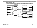
Programming Examples 6
Remote register (RWr, RWw)
In a sample program, communication is performed in remote registers as shown in the figure below.
Master station
(station No. 0)
Master PC
2E0H
2EFH
2F0H
~
FROM
BFM#8(RWr0)
D25~D10
Remote register (RWw)
RWr10
BFM#8(RWw0)
RWr17
~
2F7H
TO
BFM#23(RWrF)
RWrF
~
D707~D700
FROM
Remote register (RWr)
RWr0
~
D515~D500
Remote device station (station No. 1)
FX2N-32CCL A
FX PC
FROM
D65~D50
BFM#23(RWwF)
1E0H
1F7H
Remote register (RWr)
RWwF
BFM#8(RWr0)
RWw10
~
TO
1EFH
1F0H
~
D807~D800
TO
~
D615~D600
Remote device station (station No. 5)
FX2N-32CCL B
FX PC
RWw0
BFM#15(RWr7)
RWw17
TO
D17~D10
Remote output (RWw)
BFM#8(RWw0)
~
CC-link
scan
FROM
D57~D50
BFM#15(RWw7)
6-4
FX2N-32CCL CC-Link Interface Block
6.3
Programming Examples 6
Program in master PC
When the PC CPU starts to run, data linking is automatically started by the program shown below.
During debugging
X0000
Parameter
setting
X000F
PLS
M300
SET
M301
MOV
K2
D0
Number of connected units
MOV
K7
D1
MOV
K1
D2
H0001
D0
K3
Number of retries
Number of automatic double row
units
Write from D2 to D0 to H0001
MOV
K0
D3
Specification of operation at CPU down (stop)
H0006
D3
K1
Write from D3 to H0006
MOV
H1401
D4
MOV
H1205
D5
Station information A side
(remote device, 4 stations occupied, station No. 1)
Station information B side
(remote device, 2 stations occupied, station No. 5)
H0020
D4
K2
RST
M301
Unit error Unit ready
M300
M301
TO
M301
TO
TO
H0000
H0000
H0000
Write from D5 and D4 to H0020
6-5
FX2N-32CCL CC-Link Interface Block
Programming Examples 6
M 9038
SET
Y00
Initial pu lse
X 0000
X 000F
P LS
M 302
SET
M 303
SET
Y06
RST
Y06
Instruction
of refresh
D ata link by
param eter of
buffer m em ory
M 302
M 303
D ata link startup request by param eter of
buffer m em ory
X 0006
S tartup
no rm al
com ple tion
RST
M 303
D 100
K1
RST
Y06
RST
M 303
W hen data link start up is norm ally
com pleted by param eter of buffer m em ory
X 0007
S tartup
ab norm al
com ple tion
FROM
H 0000
H 0668
W hen data link start up is abnorm ally
com pleted by param eter of buffer m em ory
6-6
FX2N-32CCL CC-Link Interface Block
R e gis tra tio n
co m m a n d X 0000
Programming Examples 6
P a ra m e te r
reg istration to
EEPROM
X 000F
P LS
M 304
SET
M 305
SET
Y0A
RST
Y0A
M 304
M 305
P aram eter registration request to E E P R O M
X 000A
R e gis tra tio n n orm al
co m ple tio n
RST
M 305
D 101
K1
RST
Y0A
RST
M 305
W hen param eter registration to E E P R O M
is norm ally com pleted
X 000B
FROM
R e gis tra tio n
a bn orm al
co m ple tio n
H 0000
H 06B 9
W hen param eter registration to E E P R O M
is abnorm ally com pleted
6-7
FX2N-32CCL CC-Link Interface Block
Programming Examples 6
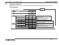
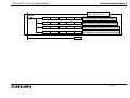
During operation
M 9038
SET
Y00
In itia l p ulse
X 0000
X 000F
P LS
M 300
P LS
M 301
SET
Y08
RST
Y08
RST
M 301
D 100
K1
RST
Y08
RST
M 301
Instruction
of refresh
D ata link by
param eter of
EEPRO M
U n it e rro r U n it rea d y
M 300
M 301
D ata link startup request by param eter of
EEPRO M
X 0008
S ta rtup
n orm a l
co m ple tio n
W hen data link startup is norm ally
com pleted by param eter of E E P R O M
X 0009
S ta rtup
a bn orm al
co m ple tio n
FROM
H 0000
H 0668
W hen data link startup is abnorm ally
com pleted by param eter of E E P R O M
6-8
FX2N-32CCL CC-Link Interface Block
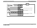
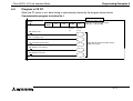
Programming Examples 6
Program for communication with remote device station
X0000
X000F
X0001
FROM
Unit error Unit ready Data link
status
H0000
H0680
K2M401
K1
Data link status (SW0080) of
remote device station is read.
CALL
P10
FX2N-32CCL (station No. 1)
Data link being executed
Y20
FX2N-32CCL (station No. 1)
Data link error
P20
FX2N-32CCL (station No. 5)
Data link being executed
Y21
FX2N-32CCL (station No. 5)
Data link error
M401
Link normal (station No. 1)
M401
Link error (station No. 1)
M405
Link normal (station No. 5)
M405
CALL
Link error (station No. 5)
FEND
Communication with
FX2N-32CCL (station No. 1)
M9036
P10
Always
ON
FROM
H0000
H00E0
K4M500
K8
Read of remote input
E7H to E0H (RX7F to RX00) → M627 to M500
TO
H0000
H0160
K4M700
K8
Write of remote output
M827 to M700→167H to 160H (RY7F to RY00)
FROM
H0000
H02E0
D500
K16
Read of remote register (RWr)
2EFH to 2E0H (RWrF to RWr0) → D515 to D500
TO
H0000
H01E0
D600
K16
Write of remote register (RWw)
D615 to D600 → 1EFH to 1E0H (RWwF to RWw0)
6-9
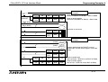
FX2N-32CCL CC-Link Interface Block
Programming Examples 6
Communication with FX2N32CCL (station No. 5)
M9036
P20
Always
ON
FROM
H0000
H00E8
K4M900
K4
Read of remote input
EBH to E8H (RXBF to RX80) → M963 to M900
TO
H0000
H0168 K4M1000
K4
Write of remote output
M1063 to M1000 →16BH to 168H (RYBF to RY80)
FROM
H0000
H02F0
D700
K8
Read of remote register (RWr)
2F7H to 2F0H (RWr17 to RWr10) → D707 to D700
TO
H0000
H01F0
D800
K8
Write of remote register (RWw)
D807 to D800 → 1F7H to 1F0H (RWw17 to RWw10)
RET
6-10
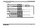
FX2N-32CCL CC-Link Interface Block
6.4
Programming Examples 6
Program in FX PC
When the PC starts to run, data linking is automatically started by the program shown below.
Communication program in station No. 1
M 8000
F N C 78
FROM
K0
K 25
K 4M 0
B lo ck N o. B F M .N o . T ra ns fer
d estina tio n
K1
R ead of
com m unication status
R ead of com m unication status
B F M #25 → M 15 to M 0
N u m be r of
tran sfe r
p oin ts
M 0 C R C error
M 1 T im eout error
M 7 Link being executed
Indication of com m unication status
(upon necessity)
M 8 M aster P C running
M 9 M aster P C error
6-11
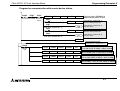
FX2N-32CCL CC-Link Interface Block
M7
Link being
executed
Programming Examples 6
FNC78
FROM
K0
K0
K4M300
K8
Read of remote output
and register
Read of remote output
BFM #7 to #0 (RY7F to RY00) → M427 to M300
FNC78
FROM
K0
K8
D50
K16
Read of remote register
BFM #23 to #8 (RWwF to RWw0) → D65 to D50
M300 (RY00)
M412 (RY6F)
Utilization of read result
FNC12
MOV
D50
D
FNC12
MOV
D65
D
Write of remote input
and register
(RX00)
(RX6F)
M7
M100
M212
FNC12
MOV
K30
D10
FNC12
MOV
D100
D25
Program determining the ON/OFF status of
remote input and the remote register value to be
written
FNC79
TO
K0
K0
K4M100
K8
Write of remote input
M227 to M100 → BFM #7 to #0 (RX7F to RX00)
FNC79
TO
K0
K8
D10
K16
Write of remote register
D25 to D10 → BFM #23 to #8 (RWrF to RWr0)
6-12
FX2N-32CCL CC-Link Interface Block
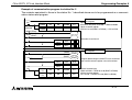
Programming Examples 6
Example of communication program in station No. 2
The contents equivalent to those in the station No. 1 described above are to be programmed as a communication status read program.
M7
Link being
executed
FNC78
FROM
K0
K0
K4M300
K4
Read of remote output
and register
Read of remote output
BFM #3 to #0 (RY3F to RY00) → M363 to M300
FNC78
FROM
K0
K8
D50
K8
Read of remote register
BFM #15 to #8 (RWw7 to RWw0) → D57 to D50
FNC12
MOV
D50
D
FNC12
MOV
D57
D
M300 (RY00)
M363 (RY3F)
Utilization of read result
(RX00)
(RX3F)
M7
Write of remote input
and register
M100
M163
FNC12
MOV
K30
D10
FNC12
MOV
D100
D17
Program determining the ON/OFF status of remote
input and the remote register value to be written
FNC79
TO
K0
K0
K4M100
K4
Write of remote input
M163 to M100 → BFM #3 to #0 (RX3F to RX00)
FNC79
TO
K0
K8
D10
K8
Write of remote register
D17 to D10 → BFM #15 to #8 (RWr7 to RWr0)
6-13
FX2N-32CCL CC-Link Interface Block
Programming Examples 6
Memo
6-14
USER’S MANUAL
CC-Link INTERFACE BLOCK FX2N-32CCL
HEAD OFFICE: TOKYO BUILDING, 2-7-3 MARUNOUCHI, CHIYODA-KU, TOKYO 100-8310, JAPAN
HIMEJI WORKS: 840, CHIYODA CHO, HIMEJI, JAPAN
MODEL
FX2N-32CCL-U-E
MODEL CODE
09R711
JY992D71801E
(MEE)
Effective June 2008
Specifications are subject to change without notice.