1
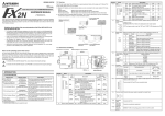
Side B Side JAPANESE Side ENGLISH A B FX 1S, FX 1N , FX2N , FX 2NC Series Programming Manual JY992D88101 MODEL CODE: 09R512 Depending on the circumstances, procedures indicated by also cause severe injury. It is important to follow all precautions for personal safety. may Associated Manuals Description FX2N-32CCL User's Manual JY992D71801 MODEL CODE: 09R711 Describes details of the FX 2N 32CCL CC-Link Interface block. FX3G Series User’s Manual - Hardware Edition JY997D31301 MODEL CODE: 09R521 Explains the FX 3G Series PLC specifications for I/O, wiring, installation, and maintenance. FX3GC Series User’s Manual - Hardware Edition JY997D45401 MODEL CODE: 09R533 Explains the FX3GC Series PLC specifications for I/O, wiring, installation, and maintenance. FX3U Series User’s Manual - Hardware Edition JY997D16501 MODEL CODE: 09R516 Explains the FX 3U Series PLC specifications for I/O, wiring, installation, and maintenance. FX3UC Series User’s Manual - Hardware Edition JY997D28701 MODEL CODE: 09R519 Explains the FX 3UC Series PLC specifications for I/O, wiring, installation, and maintenance. FX2N Series H A R D WA R E MANUAL JY992D66301 MODEL CODE: 09R508 Explains FX2N Series PLC specification details for I/O, wiring, installation, and maintenance. JY992D87201 Explains FX 2NC (D/UL) Series PLC specification details for I/O, wiring, installation, and maintenance. Explains instructions applicable in the FX1S/FX1N/FX2N/FX2NC PLC. 1 sheet Dust proof protection sheet 1 sheet Manuals (Japanese version, English version) INSTALLATION PRECAUTIONS Make sure to cut off all phases of the power supply externally before attempting installation work. Failure to do so may cause electric shock or damage to the product. INSTALLATION PRECAUTIONS Use the product within the generic environment specifications described in section 3.2 of this manual. Never use the product in areas with excessive dust, oily smoke, conductive dusts, corrosive gas (salt air, Cl 2 , H 2 S, SO 2 , or NO 2 ), flammable gas, vibration or impacts, or expose it to high temperature, condensation, or rain and wind. If the product is used in such conditions, electric shock, fire, malfunctions, deterioration or damage may occur. Do not touch the conductive parts of the product directly. Doing so may cause device failures or malfunctions. Install the product securely using a DIN rail or mounting screws. Install the product on a flat surface. If the mounting surface is rough, undue force will be applied to the PC board, thereby causing nonconformities. When drilling screw holes or wiring, make sure that cutting and wiring debris do not enter the ventilation slits. Failure to do so may cause fire, equipment failures or malfunctions. Be sure to remove the dust proof sheet from the PLC's ventilation port when installation work is completed. Failure to do so may cause fire, equipment failures or malfunctions. Make sure to attach the top cover, offered as an accessory, before turning on the power or initiating operation after installation or wiring work. Failure to do so may cause electric shock. Connect extension cables securely to their designated connectors. Loose connections may cause malfunctions. 2.1 Connection with PLC The FX2N-32CCL connects on the right side of an PLC main unit or extension units/blocks (including special function units/blocks). For connection to the FX2NC Series PLC or an extension block of the FX2NC Series PLC, use an FX2NC-CNV-IF. For connection to the FX3GC/FX3UC Series PLC or a special function block of the FX3UC Series PLC, use an FX2NC-CNV-IF or FX3UC-1PS-5V. For details, refer to the respective PLC user's manual hardware edition or hardware manual. 2.2 Mounting The product is mounted by the following method. DIN rail mounting Direct mounting (mounting screw: M4 screw) For details, refer to the respective PLC user's manual - hardware edition or hardware manual. 3. Specification For details on specifications, refer to the following manual. Refer to the FX2N-32CCL User's Manual. [1] This note does not guarantee that an entire mechanical module produced in accordance with the contents of this note will comply with the following standards. Compliance to EMC directive and LVD directive for the entire mechanical module should be checked by the user / manufacturer. For more information please consult with your nearest Mitsubishi product provider. Regarding the standards that comply with the main unit, please refer to either the FX series product catalog or consult with your nearest Mitsubishi product provider. [3] 87 (3.42") 43 (1.69") [Without top cover] [8] [10] [11] C omp lia nce w ith a ll rele van t aspe cts of th e standard. • Emission-Enclosure port • Emission-Low voltage AC mains port • Emission-Telecommunications/network port EN61131-2:2007 Programmable controllers - Equipment requirements and tests C omp lia nce w ith a ll rele van t aspe cts of th e standard. EMI • Radiated Emission • Conducted Emission EMS • Radiated electromagnetic field • Fast transient burst • Electrostatic discharge • High-energy surge • Voltage drops and interruptions • Conducted RF • Power frequency magnetic field [7] DIN rail mounting hook Power supply terminal block [9] Station No. set switch 0 Transmission speed 156 Kbps [10] Number of occupied stations set switch 1 Transmission speed 625 Kbps [11] Baud rate set switch 2 Transmission speed 2.5 Mbps [4] Status LEDs [12] Next step extension connector 3 Transmission speed 5 Mbps [5] Name plate [13] CC-Link connection terminal block 4 Transmission speed 10 Mbps [6] DIN rail mounting groove (DIN rail: DIN46277, 35 mm (1.38") width) 1.6.3 LED color Description green 3.1 Applicable PLC FX0N/FX1N/FX2N/FX2NC/FX3G/FX3GC/FX3U/FX3UC 3.2 General Specification Items other than the following are equivalent to those of the PLC main unit. For general specifications, refer to the respective PLC user's manual - hardware edition or hardware manual. Specification Dielectric withstand 500 V AC for one minute voltage Lit while communication is performed correctly. Red Lit when a communication error has occurred. Lit when a rotary switch is incorrectly set. Flickers when setting of a rotary switch is changed while the power is turned on. Red Lit while data is received. SD Red Lit while data is sent. Specification By FROM and TO instructions or direct specification*1 of buffer memory via the buffer memory. Number of I/O occupied 8 points points *1 FX3U/FX3UC Series PLC can use direct specification of buffer memory. Refer to the FX 3S /FX 3G /FX 3GC/FX 3U/FX 3UC Series Programming Manual - Basic & Applied Instruction Edition for details. Maximum transmission distance varies depending on the transmission speed. Remote I/O station Remote device station Master station Item Current consumption 50 mA (Supplied from external terminal) Control power supply Power supply voltage 5 V DC Current consumption 130 mA (Supplied from PLC via extension cable) CC-Link applicable version Ver. 1.00 Station number 1 to 64 (set by rotary switch) 1 to 4 (set by rotary switch) 156 Kbps/625 Kbps/2.5 Mbps/5 Mbps/10 Mbps (set by rotary switch) Maximum total cable length 1200 m maximum (maximum transmission (varies depending on the transmission speed.) distance) For details, refer to Section 3.5. Twisted pair cable F or th e m od e l na m e an d th e sp ec i fi ca ti on s of th e recommended cable, refer to the FX2N-32CCL User's Manual. 1) 156 Kbps 30 cm or more 1200 m 625 Kbps 30 cm or more 600 m 1) 2.5 Mbps 2 m or more 5 Mbps 30 cm or more 200 m 60 cm or more 150 m 10 Mbps 30 to 59 cm 110 m 1 m or more 100 m 60 to 99 cm 80 m 30 to 59 cm 50 m 1): The cable length between the master/local station and an adjacent station should be 2 m or more without regard to setting of the transmission speed. 2): When the transmission speed is 5 Mbps or 10 Mbps, the maximum transmission distance varies depending on the cable length between remote I/O stations and remote device stations. 3.6 Number of occupied station and number of remote points In the FX2N-32CCL, the number of remote points vary depending on the selected number of stations (1 to 4). 32 remote input points and 32 remote output points are available in one station. However, the upper 16 points of the final station are occupied by the CC-Link as the system area. 4 read points and 4 write points are available as remote registers in one station. Number of stations Type Remote input Remote output Remote register for write Remote register for read User area RX00 to 0F (16 points) RY00 to 0F (16 points) RWr0 to 3 (4 points) RWw0 to 3 (4 points) System area RX10 to 1F (16 points) RY10 to 1F (16 points) - - User area RX00 to 2F (48 points) RY00 to 2F (48 points) RWr0 to 7 (8 points) RWw0 to 7 (8 points) System area RX30 to 3F (16 points) RY30 to 3F (16 points) - - User area RX00 to 4F (80 points) RY00 to 4F (80 points) RWr0 to B (12 points) RWw0 to B (12 points) System area RX50 to 5F (16 points) RY50 to 5F (16 points) - - User area RX00 to 6F (112 points) RY00 to 6F (112 points) RWr0 to F (16 points) RWw0 to F (16 points) System area RX70 to 7F (16 points) RY70 to 7F (16 points) - - 1 2 3 Specification Remote device station Local station Maximum transmission distance 3.4 Performance Specification Station type Local station 2) Specification 24 V DC +10% -10% Remote I/O station Remote device station 2) 1) Maximum transmission distance Transmission speed 3.3 Power Supply Specification Power supply voltage BFM No. 4 4. Buffer memory Description BFM No. Buffer memory dedicated to read Buffer memory dedicated to write #0 Remote output RY00 to RY0F (set station) Remote input RX00 to RX0F (set station) #1 Remote output RY10 to RY1F (set station) Remote input RX10 to RX1F (set station) #2 Remote output RY20 to RY2F (set station+1) Remote input RX20 to RX2F (set station+1) Description 0 1 station 1 2 stations 2 3 stations 3 4 stations 4 to 9 Unusable Description Buffer memory dedicated to read Buffer memory dedicated to write #3 Remote output RY30 to RY3F (set station+1) Remote input RX30 to RX3F (set station+1) #4 Remote output RY40 to RY4F (set station+2) Remote input RX40 to RX4F (set station+2) #5 Remote output RY50 to RY5F (set station+2) Remote input RX50 to RX5F (set station+2) #6 Remote output RY60 to RY6F (set station+3) Remote input RX60 to RX6F (set station+3) #7 Remote output RY70 to RY7F (set station+3) Remote input RX70 to RX7F (set station+3) #8 Remote register RWw0 (set station) Remote register RWr0 (set station) #9 Remote register RWw1 (set station) Remote register RWr1 (set station) #10 Remote register RWw2 (set station) Remote register RWr2 (set station) #11 Remote register RWw3 (set station) Remote register RWr3 (set station) #12 Remote register RWw4 (set station+1) Remote register RWr4 (set station+1) #13 Remote register RWw5 (set station+1) Remote register RWr5 (set station+1) #14 Remote register RWw6 (set station+1) Remote register RWr6 (set station+1) #15 Remote register RWw7 (set station+1) Remote register RWr7 (set station+1) #16 Remote register RWw8 (set station+2) Remote register RWr8 (set station+2) #17 Remote register RWw9 (set station+2) Remote register RWr9 (set station+2) #18 Remote register RWwA (set station+2) Remote register RWrA (set station+2) 3.5 Maximum transmission distance and transmission speed Between external terminals as a whole and ground terminal Drive power supply Setting Red RD Setting error Number of occupied station setting The number of remote device points is determined by the number of stations set here. For specifications of number of occupied station and number of remote points, refer to Section 3.6. Indicates power status of FX2N-32CCL. Lighted when 5 V is supplied from PLC. Communication with PLC Please contact a certified electronic waste disposal company for the environmentally safe recycling and disposal of your device. Connection cable 5 to 9 1.4 Power and status LEDs DISPOSAL PRECAUTIONS The PLC is a precision instrument. During transportation, avoid impacts larger than those specified in the general specifications of the PLC main unit manual. Failure to do so may cause failures in the PLC. After transportation, verify the operations of the PLC. Description Power LED (green) 1) TRANSPORTATION AND STORAGE PRECAUTIONS Setting [3] DESIGN PRECAUTIONS Observe the following items. Failure to do so may cause incorrect data-writing through noise to the PLC and result in PLC failure, machine damage or other accident. 1) Do not bundle the control line together with or lay it close to the main circuit or power line. As a guideline, lay the control line at least 100 mm (3.94") or more away from the main circuit or power line. Noise may cause malfunctions. 2) Ground the shield wire or shield of a shielded cable. Do not use common grounding with heavy electrical systems. Do not apply excessive pressure to the power supply terminal block or CC-Link connection terminal block. Excessive pressure may cause damage or error. Baud rate (Transmission speed) setting [8] Item Make sure to include the following safety circuits outside the PLC to ensure safe system operation even during external power supply problems or PLC failure. Otherwise, malfunctions may cause serious accidents. 1) Above all, the following components should be included: an emergency stop circuit, a protection circuit, an interlock circuit for opposite movements (such as normal vs. reverse rotation), and an interlock circuit (to prevent damage to the equipment at the upper and lower positioning limits). 2) Note that when the PLC main unit detects an error during self diagnosis, such as a watchdog timer error, all outputs are turned off. Also, when an error that cannot be detected by the PLC main unit occurs in an input/output control block, output control may be disabled. External circuits and mechanisms should be designed to ensure safe machinery operation in such cases. Transmission speed 1 to 64 0, 65 to 99 is the setting error. Direct mounting hole 2 holes of 4.5 (0.18") (mounting screw: M4 screw) DESIGN PRECAUTIONS occupied 0 to 9 [2] L ERR of 1 Set the transmission speed in accordance with the specifications of the maximum transmission distance and the transmission speed. For specifications of the maximum transmission distance and transmission speed, refer to Section 3.5. [13] L RUN Number stations Description 0 to 6 Extension cable POWER Item Range 10 [1] LED display Item Setting items 1.6.2 Remark Station number setting One to four FX2N-32CCL units can be used at a time. Pay attention so that the station number set here is not assigned to an other unit. [12] FX2N-32CCL Standard EN61000-6-4:2007 Generic emission standard Industrial environment The station number, the number of occupied stations and the baud rate can be set using rotary switches provided inside the panel cover of the FX2N-32CCL. The switch settings become valid after FX2N-32CCL startup. If the switch settings are changed after FX2N-32CCL startup, the L ERR LED will flicker. To change the switch setting, power OFF the FX2N-32CCL once, and power it ON again. For details on the switch setting, refer to the following manual. Refer to the FX2N-32CCL User's Manual. 1.6.1 Unit: mm (inches) MASS (Weight): 0.2 kg (0.44 lbs) [9] Programmable Controller (Open Type Equipment) MELSEC FX2N series manufactured Terminal screws and tightening torque For the terminals of FX2N-32CCL, M3 screws are used. Tighten the screws to a torque of 0.5 to 0.8 Nm. Do not tighten terminal screws with a torque outside the above-mentioned range. Failure to do so may cause equipment failures or malfunctions. For details on the wiring needed to connect to the terminal blocks shown in the figure above, refer to the following manual. Refer to the FX2N-32CCL User's Manual. 1.6 Switch setting [7] 4 (0.16") The following products have shown compliance through direct testing (of the identified standards below) and design analysis (through the creation of a technical construction file) to the European Directive for Electromagnetic Compatibility (2004/108/EC) when used as directed by the appropriate documentation. Attention This product is designed for use in industrial applications. Note Authorized Representative in the European Community: Mitsubishi Electric Europe B.V. Gothaer Str. 8, 40880 Ratingen, Germany Model name [6] [4] Requirement for Compliance with EMC directive from June 1st, 1999 [5] 1.5.1 Compliance with EC directive (CE Marking) DESIGN PRECAUTIONS For the status of each station when the main unit stops calculation or when a communication error occurs in the data link, thoroughly read the description of data link processing time in the CC-Link master module manual. Construct an interlock circuit in the sequence program using the communication status information (SB, SW) so that the system always works conservatively. Erroneous outputs and malfunctions may cause accidents. When executing control (data changes) to an operating PLC, construct an interlock circuit in the sequence program so that the entire system operates conservatively. In addition, when executing control such as program changes and operation status changes (status control) to an operating PLC, thoroughly read the manual and sufficiently confirm safety in advance. Especially in control from external equipment to a PLC in a remote place, problems in the PLC may not be able to be handled promptly due to abnormality in data transfer. Construct an interlock circuit in the sequence program. At the same time, determine the actions in the system between the external equipment and the PLC for protection against abnormalities in data transfer. 2-4.5 mounting holes [2] How to obtain manuals For product manuals or documents, consult with the Mitsubishi Electric dealer from who you purchased your product. Type: Models: 1 manual each 1.3 External Dimensions and Part Names Explains FX2NC (DSS/DS) Series PLC specification details for I/O, wiring, installation, and maintenance. 2. Installation 1 unit Special unit/block No. label DG Indicates that incorrect handling may cause hazardous conditions, resulting in medium or slight personal injury or physical damage. CC-Link connection terminal block Included Item FX2N-32CCL SLD April 2015 . JY992D76401 MODEL CODE: 09R509 Explains basic instructions and applied instructions available in the FX 3S /FX 3G /FX 3GC /FX 3U /FX 3UC PLC. DB Date Indicates that incorrect handling may cause hazardous conditions, resulting in death or severe injury. FX2NC (DSS/DS) Series H A R D WA R E MANUAL JY997D16601 MODEL CODE: 09R517 Check to ensure the following product and items are included in the package. DB B This manual classifies the safety precautions into two categories: FX2NC (D/UL) Series H A R D WA R E MANUAL FX 3S /FX 3G /FX 3GC /FX 3U / FX3UC Series Programming Manual - Basic & Applied Instruction Edition FX0/FX0N Series HARDWARE MANUAL Power supply terminal block DA Revision Safety Precaution (Read these precautions before use.) Manual No. 1.2 Incorporated Items DA JY997D52401 Effective April 2015 Specifications are subject to change without notice. 2013 Mitsubishi Electric Corporation Manual name JY992D47501 Explains FX 0 /FX 0N Series PLC specification details for I/O, wiring, installation, and maintenance. FG Manual Number This manual describes the part names, dimensions, mounting, and specifications of the product. Before use, read this manual and the manuals of all relevant products fully to acquire proficiency in handling and operating the product. Make sure to learn all the product information, safety information, and precautions. Store this manual in a safe place so that it can be taken out and read whenever necessary. Always forward it to the end user. Registration: The company and product names described in this manual are registered trademarks or the trademarks of their respective companies. and The CC-Link interface block FX2N-32CCL is a special function block to connect the FX0N/FX1N/FX2N/FX2NC/FX3G/FX3GC/FX3U/FX3UC Series PLC to a CC-Link network. For details, refer to the FX2N-32CCL User's Manual. 1.1 Introduction 24- INSTALLATION MANUAL 1.5 Terminal Layout Description Explains FX1N Series PLC specification details for I/O, wiring, installation, and maintenance. FX1N Series HARDWARE MANUAL FX2N-32CCL 1. Introduction Manual No. JY992D89301 MODEL CODE: 09R511 24+ Manual name 80 (3.15") (mounting hole pitch) 90 (3.54") JY997D52401B #19 Remote register RWwB (set station+2) Remote register RWrB (set station+2) #20 Remote register RWwC (set station+3) Remote register RWrC (set station+3) #21 Remote register RWwD (set station+3) Remote register RWrD (set station+3) #22 Remote register RWwE (set station+3) Remote register RWrE (set station+3) #23 Remote register RWwF (set station+3) Remote register RWrF (set station+3) #24 Set value of baud rate Undefined (Write is disabled.) #25 Communication status Undefined (Write is disabled.) #26 CC-Link model code Undefined (Write is disabled.) #27 Set value of its own station No. Undefined (Write is disabled.) #28 Set value of number of occupied stations Undefined (Write is disabled.) #29 Error code Undefined (Write is disabled.) #30 FX Series model code (K7040) Undefined (Write is disabled.) #31 Not available Not available This manual confers no industrial property rights or any rights of any other kind, nor does it confer any patent licenses. Mitsubishi Electric Corporation cannot be held responsible for any problems involving industrial property rights which may occur as a result of using the contents noted in this manual. Warranty Mitsubishi will not be held liable for damage caused by factors found not to be the cause of Mitsubishi; opportunity loss or lost profits caused by faults in the Mitsubishi products; damage, secondary damage, accident compensation caused by special factors unpredictable by Mitsubishi; damages to products other than Mitsubishi products; and to other duties. For safe use This product has been manufactured as a general-purpose part for general industries, and has not been designed or manufactured to be incorporated in a device or system used in purposes related to human life. Before using the product for special purposes such as nuclear power, electric power, aerospace, medicine or passenger movement vehicles, consult with Mitsubishi Electric. This product has been manufactured under strict quality control. However when installing the product where major accidents or losses could occur if the product fails, install appropriate backup or failsafe functions in the system. HEAD OFFICE : TOKYO BUILDING, 2-7-3 MARUNOUCHI, CHIYODA-KU, TOKYO 100-8310, JAPAN Side B Side JAPANESE Side ENGLISH A B FX 1S, FX 1N , FX2N , FX 2NC Series Programming Manual JY992D88101 MODEL CODE: 09R512 Depending on the circumstances, procedures indicated by also cause severe injury. It is important to follow all precautions for personal safety. may Associated Manuals Description FX2N-32CCL User's Manual JY992D71801 MODEL CODE: 09R711 Describes details of the FX 2N 32CCL CC-Link Interface block. FX3G Series User’s Manual - Hardware Edition JY997D31301 MODEL CODE: 09R521 Explains the FX 3G Series PLC specifications for I/O, wiring, installation, and maintenance. FX3GC Series User’s Manual - Hardware Edition JY997D45401 MODEL CODE: 09R533 Explains the FX3GC Series PLC specifications for I/O, wiring, installation, and maintenance. FX3U Series User’s Manual - Hardware Edition JY997D16501 MODEL CODE: 09R516 Explains the FX 3U Series PLC specifications for I/O, wiring, installation, and maintenance. FX3UC Series User’s Manual - Hardware Edition JY997D28701 MODEL CODE: 09R519 Explains the FX 3UC Series PLC specifications for I/O, wiring, installation, and maintenance. FX2N Series H A R D WA R E MANUAL JY992D66301 MODEL CODE: 09R508 Explains FX2N Series PLC specification details for I/O, wiring, installation, and maintenance. JY992D87201 Explains FX 2NC (D/UL) Series PLC specification details for I/O, wiring, installation, and maintenance. Explains instructions applicable in the FX1S/FX1N/FX2N/FX2NC PLC. 1 sheet Dust proof protection sheet 1 sheet Manuals (Japanese version, English version) INSTALLATION PRECAUTIONS Make sure to cut off all phases of the power supply externally before attempting installation work. Failure to do so may cause electric shock or damage to the product. INSTALLATION PRECAUTIONS Use the product within the generic environment specifications described in section 3.2 of this manual. Never use the product in areas with excessive dust, oily smoke, conductive dusts, corrosive gas (salt air, Cl 2 , H 2 S, SO 2 , or NO 2 ), flammable gas, vibration or impacts, or expose it to high temperature, condensation, or rain and wind. If the product is used in such conditions, electric shock, fire, malfunctions, deterioration or damage may occur. Do not touch the conductive parts of the product directly. Doing so may cause device failures or malfunctions. Install the product securely using a DIN rail or mounting screws. Install the product on a flat surface. If the mounting surface is rough, undue force will be applied to the PC board, thereby causing nonconformities. When drilling screw holes or wiring, make sure that cutting and wiring debris do not enter the ventilation slits. Failure to do so may cause fire, equipment failures or malfunctions. Be sure to remove the dust proof sheet from the PLC's ventilation port when installation work is completed. Failure to do so may cause fire, equipment failures or malfunctions. Make sure to attach the top cover, offered as an accessory, before turning on the power or initiating operation after installation or wiring work. Failure to do so may cause electric shock. Connect extension cables securely to their designated connectors. Loose connections may cause malfunctions. 2.1 Connection with PLC The FX2N-32CCL connects on the right side of an PLC main unit or extension units/blocks (including special function units/blocks). For connection to the FX2NC Series PLC or an extension block of the FX2NC Series PLC, use an FX2NC-CNV-IF. For connection to the FX3GC/FX3UC Series PLC or a special function block of the FX3UC Series PLC, use an FX2NC-CNV-IF or FX3UC-1PS-5V. For details, refer to the respective PLC user's manual hardware edition or hardware manual. 2.2 Mounting The product is mounted by the following method. DIN rail mounting Direct mounting (mounting screw: M4 screw) For details, refer to the respective PLC user's manual - hardware edition or hardware manual. 3. Specification For details on specifications, refer to the following manual. Refer to the FX2N-32CCL User's Manual. [1] This note does not guarantee that an entire mechanical module produced in accordance with the contents of this note will comply with the following standards. Compliance to EMC directive and LVD directive for the entire mechanical module should be checked by the user / manufacturer. For more information please consult with your nearest Mitsubishi product provider. Regarding the standards that comply with the main unit, please refer to either the FX series product catalog or consult with your nearest Mitsubishi product provider. [3] 87 (3.42") 43 (1.69") [Without top cover] [8] [10] [11] C omp lia nce w ith a ll rele van t aspe cts of th e standard. • Emission-Enclosure port • Emission-Low voltage AC mains port • Emission-Telecommunications/network port EN61131-2:2007 Programmable controllers - Equipment requirements and tests C omp lia nce w ith a ll rele van t aspe cts of th e standard. EMI • Radiated Emission • Conducted Emission EMS • Radiated electromagnetic field • Fast transient burst • Electrostatic discharge • High-energy surge • Voltage drops and interruptions • Conducted RF • Power frequency magnetic field [7] DIN rail mounting hook Power supply terminal block [9] Station No. set switch 0 Transmission speed 156 Kbps [10] Number of occupied stations set switch 1 Transmission speed 625 Kbps [11] Baud rate set switch 2 Transmission speed 2.5 Mbps [4] Status LEDs [12] Next step extension connector 3 Transmission speed 5 Mbps [5] Name plate [13] CC-Link connection terminal block 4 Transmission speed 10 Mbps [6] DIN rail mounting groove (DIN rail: DIN46277, 35 mm (1.38") width) 1.6.3 LED color Description green 3.1 Applicable PLC FX0N/FX1N/FX2N/FX2NC/FX3G/FX3GC/FX3U/FX3UC 3.2 General Specification Items other than the following are equivalent to those of the PLC main unit. For general specifications, refer to the respective PLC user's manual - hardware edition or hardware manual. Specification Dielectric withstand 500 V AC for one minute voltage Lit while communication is performed correctly. Red Lit when a communication error has occurred. Lit when a rotary switch is incorrectly set. Flickers when setting of a rotary switch is changed while the power is turned on. Red Lit while data is received. SD Red Lit while data is sent. Specification By FROM and TO instructions or direct specification*1 of buffer memory via the buffer memory. Number of I/O occupied 8 points points *1 FX3U/FX3UC Series PLC can use direct specification of buffer memory. Refer to the FX 3S /FX 3G /FX 3GC/FX 3U/FX 3UC Series Programming Manual - Basic & Applied Instruction Edition for details. Maximum transmission distance varies depending on the transmission speed. Remote I/O station Remote device station Master station Item Current consumption 50 mA (Supplied from external terminal) Control power supply Power supply voltage 5 V DC Current consumption 130 mA (Supplied from PLC via extension cable) CC-Link applicable version Ver. 1.00 Station number 1 to 64 (set by rotary switch) 1 to 4 (set by rotary switch) 156 Kbps/625 Kbps/2.5 Mbps/5 Mbps/10 Mbps (set by rotary switch) Maximum total cable length 1200 m maximum (maximum transmission (varies depending on the transmission speed.) distance) For details, refer to Section 3.5. Twisted pair cable F or th e m od e l na m e an d th e sp ec i fi ca ti on s of th e recommended cable, refer to the FX2N-32CCL User's Manual. 1) 156 Kbps 30 cm or more 1200 m 625 Kbps 30 cm or more 600 m 1) 2.5 Mbps 2 m or more 5 Mbps 30 cm or more 200 m 60 cm or more 150 m 10 Mbps 30 to 59 cm 110 m 1 m or more 100 m 60 to 99 cm 80 m 30 to 59 cm 50 m 1): The cable length between the master/local station and an adjacent station should be 2 m or more without regard to setting of the transmission speed. 2): When the transmission speed is 5 Mbps or 10 Mbps, the maximum transmission distance varies depending on the cable length between remote I/O stations and remote device stations. 3.6 Number of occupied station and number of remote points In the FX2N-32CCL, the number of remote points vary depending on the selected number of stations (1 to 4). 32 remote input points and 32 remote output points are available in one station. However, the upper 16 points of the final station are occupied by the CC-Link as the system area. 4 read points and 4 write points are available as remote registers in one station. Number of stations Type Remote input Remote output Remote register for write Remote register for read User area RX00 to 0F (16 points) RY00 to 0F (16 points) RWr0 to 3 (4 points) RWw0 to 3 (4 points) System area RX10 to 1F (16 points) RY10 to 1F (16 points) - - User area RX00 to 2F (48 points) RY00 to 2F (48 points) RWr0 to 7 (8 points) RWw0 to 7 (8 points) System area RX30 to 3F (16 points) RY30 to 3F (16 points) - - User area RX00 to 4F (80 points) RY00 to 4F (80 points) RWr0 to B (12 points) RWw0 to B (12 points) System area RX50 to 5F (16 points) RY50 to 5F (16 points) - - User area RX00 to 6F (112 points) RY00 to 6F (112 points) RWr0 to F (16 points) RWw0 to F (16 points) System area RX70 to 7F (16 points) RY70 to 7F (16 points) - - 1 2 3 Specification Remote device station Local station Maximum transmission distance 3.4 Performance Specification Station type Local station 2) Specification 24 V DC +10% -10% Remote I/O station Remote device station 2) 1) Maximum transmission distance Transmission speed 3.3 Power Supply Specification Power supply voltage BFM No. 4 4. Buffer memory Description BFM No. Buffer memory dedicated to read Buffer memory dedicated to write #0 Remote output RY00 to RY0F (set station) Remote input RX00 to RX0F (set station) #1 Remote output RY10 to RY1F (set station) Remote input RX10 to RX1F (set station) #2 Remote output RY20 to RY2F (set station+1) Remote input RX20 to RX2F (set station+1) Description 0 1 station 1 2 stations 2 3 stations 3 4 stations 4 to 9 Unusable Description Buffer memory dedicated to read Buffer memory dedicated to write #3 Remote output RY30 to RY3F (set station+1) Remote input RX30 to RX3F (set station+1) #4 Remote output RY40 to RY4F (set station+2) Remote input RX40 to RX4F (set station+2) #5 Remote output RY50 to RY5F (set station+2) Remote input RX50 to RX5F (set station+2) #6 Remote output RY60 to RY6F (set station+3) Remote input RX60 to RX6F (set station+3) #7 Remote output RY70 to RY7F (set station+3) Remote input RX70 to RX7F (set station+3) #8 Remote register RWw0 (set station) Remote register RWr0 (set station) #9 Remote register RWw1 (set station) Remote register RWr1 (set station) #10 Remote register RWw2 (set station) Remote register RWr2 (set station) #11 Remote register RWw3 (set station) Remote register RWr3 (set station) #12 Remote register RWw4 (set station+1) Remote register RWr4 (set station+1) #13 Remote register RWw5 (set station+1) Remote register RWr5 (set station+1) #14 Remote register RWw6 (set station+1) Remote register RWr6 (set station+1) #15 Remote register RWw7 (set station+1) Remote register RWr7 (set station+1) #16 Remote register RWw8 (set station+2) Remote register RWr8 (set station+2) #17 Remote register RWw9 (set station+2) Remote register RWr9 (set station+2) #18 Remote register RWwA (set station+2) Remote register RWrA (set station+2) 3.5 Maximum transmission distance and transmission speed Between external terminals as a whole and ground terminal Drive power supply Setting Red RD Setting error Number of occupied station setting The number of remote device points is determined by the number of stations set here. For specifications of number of occupied station and number of remote points, refer to Section 3.6. Indicates power status of FX2N-32CCL. Lighted when 5 V is supplied from PLC. Communication with PLC Please contact a certified electronic waste disposal company for the environmentally safe recycling and disposal of your device. Connection cable 5 to 9 1.4 Power and status LEDs DISPOSAL PRECAUTIONS The PLC is a precision instrument. During transportation, avoid impacts larger than those specified in the general specifications of the PLC main unit manual. Failure to do so may cause failures in the PLC. After transportation, verify the operations of the PLC. Description Power LED (green) 1) TRANSPORTATION AND STORAGE PRECAUTIONS Setting [3] DESIGN PRECAUTIONS Observe the following items. Failure to do so may cause incorrect data-writing through noise to the PLC and result in PLC failure, machine damage or other accident. 1) Do not bundle the control line together with or lay it close to the main circuit or power line. As a guideline, lay the control line at least 100 mm (3.94") or more away from the main circuit or power line. Noise may cause malfunctions. 2) Ground the shield wire or shield of a shielded cable. Do not use common grounding with heavy electrical systems. Do not apply excessive pressure to the power supply terminal block or CC-Link connection terminal block. Excessive pressure may cause damage or error. Baud rate (Transmission speed) setting [8] Item Make sure to include the following safety circuits outside the PLC to ensure safe system operation even during external power supply problems or PLC failure. Otherwise, malfunctions may cause serious accidents. 1) Above all, the following components should be included: an emergency stop circuit, a protection circuit, an interlock circuit for opposite movements (such as normal vs. reverse rotation), and an interlock circuit (to prevent damage to the equipment at the upper and lower positioning limits). 2) Note that when the PLC main unit detects an error during self diagnosis, such as a watchdog timer error, all outputs are turned off. Also, when an error that cannot be detected by the PLC main unit occurs in an input/output control block, output control may be disabled. External circuits and mechanisms should be designed to ensure safe machinery operation in such cases. Transmission speed 1 to 64 0, 65 to 99 is the setting error. Direct mounting hole 2 holes of 4.5 (0.18") (mounting screw: M4 screw) DESIGN PRECAUTIONS occupied 0 to 9 [2] L ERR of 1 Set the transmission speed in accordance with the specifications of the maximum transmission distance and the transmission speed. For specifications of the maximum transmission distance and transmission speed, refer to Section 3.5. [13] L RUN Number stations Description 0 to 6 Extension cable POWER Item Range 10 [1] LED display Item Setting items 1.6.2 Remark Station number setting One to four FX2N-32CCL units can be used at a time. Pay attention so that the station number set here is not assigned to an other unit. [12] FX2N-32CCL Standard EN61000-6-4:2007 Generic emission standard Industrial environment The station number, the number of occupied stations and the baud rate can be set using rotary switches provided inside the panel cover of the FX2N-32CCL. The switch settings become valid after FX2N-32CCL startup. If the switch settings are changed after FX2N-32CCL startup, the L ERR LED will flicker. To change the switch setting, power OFF the FX2N-32CCL once, and power it ON again. For details on the switch setting, refer to the following manual. Refer to the FX2N-32CCL User's Manual. 1.6.1 Unit: mm (inches) MASS (Weight): 0.2 kg (0.44 lbs) [9] Programmable Controller (Open Type Equipment) MELSEC FX2N series manufactured Terminal screws and tightening torque For the terminals of FX2N-32CCL, M3 screws are used. Tighten the screws to a torque of 0.5 to 0.8 Nm. Do not tighten terminal screws with a torque outside the above-mentioned range. Failure to do so may cause equipment failures or malfunctions. For details on the wiring needed to connect to the terminal blocks shown in the figure above, refer to the following manual. Refer to the FX2N-32CCL User's Manual. 1.6 Switch setting [7] 4 (0.16") The following products have shown compliance through direct testing (of the identified standards below) and design analysis (through the creation of a technical construction file) to the European Directive for Electromagnetic Compatibility (2004/108/EC) when used as directed by the appropriate documentation. Attention This product is designed for use in industrial applications. Note Authorized Representative in the European Community: Mitsubishi Electric Europe B.V. Gothaer Str. 8, 40880 Ratingen, Germany Model name [6] [4] Requirement for Compliance with EMC directive from June 1st, 1999 [5] 1.5.1 Compliance with EC directive (CE Marking) DESIGN PRECAUTIONS For the status of each station when the main unit stops calculation or when a communication error occurs in the data link, thoroughly read the description of data link processing time in the CC-Link master module manual. Construct an interlock circuit in the sequence program using the communication status information (SB, SW) so that the system always works conservatively. Erroneous outputs and malfunctions may cause accidents. When executing control (data changes) to an operating PLC, construct an interlock circuit in the sequence program so that the entire system operates conservatively. In addition, when executing control such as program changes and operation status changes (status control) to an operating PLC, thoroughly read the manual and sufficiently confirm safety in advance. Especially in control from external equipment to a PLC in a remote place, problems in the PLC may not be able to be handled promptly due to abnormality in data transfer. Construct an interlock circuit in the sequence program. At the same time, determine the actions in the system between the external equipment and the PLC for protection against abnormalities in data transfer. 2-4.5 mounting holes [2] How to obtain manuals For product manuals or documents, consult with the Mitsubishi Electric dealer from who you purchased your product. Type: Models: 1 manual each 1.3 External Dimensions and Part Names Explains FX2NC (DSS/DS) Series PLC specification details for I/O, wiring, installation, and maintenance. 2. Installation 1 unit Special unit/block No. label DG Indicates that incorrect handling may cause hazardous conditions, resulting in medium or slight personal injury or physical damage. CC-Link connection terminal block Included Item FX2N-32CCL SLD April 2015 . JY992D76401 MODEL CODE: 09R509 Explains basic instructions and applied instructions available in the FX 3S /FX 3G /FX 3GC /FX 3U /FX 3UC PLC. DB Date Indicates that incorrect handling may cause hazardous conditions, resulting in death or severe injury. FX2NC (DSS/DS) Series H A R D WA R E MANUAL JY997D16601 MODEL CODE: 09R517 Check to ensure the following product and items are included in the package. DB B This manual classifies the safety precautions into two categories: FX2NC (D/UL) Series H A R D WA R E MANUAL FX 3S /FX 3G /FX 3GC /FX 3U / FX3UC Series Programming Manual - Basic & Applied Instruction Edition FX0/FX0N Series HARDWARE MANUAL Power supply terminal block DA Revision Safety Precaution (Read these precautions before use.) Manual No. 1.2 Incorporated Items DA JY997D52401 Effective April 2015 Specifications are subject to change without notice. 2013 Mitsubishi Electric Corporation Manual name JY992D47501 Explains FX 0 /FX 0N Series PLC specification details for I/O, wiring, installation, and maintenance. FG Manual Number This manual describes the part names, dimensions, mounting, and specifications of the product. Before use, read this manual and the manuals of all relevant products fully to acquire proficiency in handling and operating the product. Make sure to learn all the product information, safety information, and precautions. Store this manual in a safe place so that it can be taken out and read whenever necessary. Always forward it to the end user. Registration: The company and product names described in this manual are registered trademarks or the trademarks of their respective companies. and The CC-Link interface block FX2N-32CCL is a special function block to connect the FX0N/FX1N/FX2N/FX2NC/FX3G/FX3GC/FX3U/FX3UC Series PLC to a CC-Link network. For details, refer to the FX2N-32CCL User's Manual. 1.1 Introduction 24- INSTALLATION MANUAL 1.5 Terminal Layout Description Explains FX1N Series PLC specification details for I/O, wiring, installation, and maintenance. FX1N Series HARDWARE MANUAL FX2N-32CCL 1. Introduction Manual No. JY992D89301 MODEL CODE: 09R511 24+ Manual name 80 (3.15") (mounting hole pitch) 90 (3.54") JY997D52401B #19 Remote register RWwB (set station+2) Remote register RWrB (set station+2) #20 Remote register RWwC (set station+3) Remote register RWrC (set station+3) #21 Remote register RWwD (set station+3) Remote register RWrD (set station+3) #22 Remote register RWwE (set station+3) Remote register RWrE (set station+3) #23 Remote register RWwF (set station+3) Remote register RWrF (set station+3) #24 Set value of baud rate Undefined (Write is disabled.) #25 Communication status Undefined (Write is disabled.) #26 CC-Link model code Undefined (Write is disabled.) #27 Set value of its own station No. Undefined (Write is disabled.) #28 Set value of number of occupied stations Undefined (Write is disabled.) #29 Error code Undefined (Write is disabled.) #30 FX Series model code (K7040) Undefined (Write is disabled.) #31 Not available Not available This manual confers no industrial property rights or any rights of any other kind, nor does it confer any patent licenses. Mitsubishi Electric Corporation cannot be held responsible for any problems involving industrial property rights which may occur as a result of using the contents noted in this manual. Warranty Mitsubishi will not be held liable for damage caused by factors found not to be the cause of Mitsubishi; opportunity loss or lost profits caused by faults in the Mitsubishi products; damage, secondary damage, accident compensation caused by special factors unpredictable by Mitsubishi; damages to products other than Mitsubishi products; and to other duties. For safe use This product has been manufactured as a general-purpose part for general industries, and has not been designed or manufactured to be incorporated in a device or system used in purposes related to human life. Before using the product for special purposes such as nuclear power, electric power, aerospace, medicine or passenger movement vehicles, consult with Mitsubishi Electric. This product has been manufactured under strict quality control. However when installing the product where major accidents or losses could occur if the product fails, install appropriate backup or failsafe functions in the system. HEAD OFFICE : TOKYO BUILDING, 2-7-3 MARUNOUCHI, CHIYODA-KU, TOKYO 100-8310, JAPAN Side B Side JAPANESE Side ENGLISH A B FX 1S, FX 1N , FX2N , FX 2NC Series Programming Manual JY992D88101 MODEL CODE: 09R512 Depending on the circumstances, procedures indicated by also cause severe injury. It is important to follow all precautions for personal safety. may Associated Manuals Description FX2N-32CCL User's Manual JY992D71801 MODEL CODE: 09R711 Describes details of the FX 2N 32CCL CC-Link Interface block. FX3G Series User’s Manual - Hardware Edition JY997D31301 MODEL CODE: 09R521 Explains the FX 3G Series PLC specifications for I/O, wiring, installation, and maintenance. FX3GC Series User’s Manual - Hardware Edition JY997D45401 MODEL CODE: 09R533 Explains the FX3GC Series PLC specifications for I/O, wiring, installation, and maintenance. FX3U Series User’s Manual - Hardware Edition JY997D16501 MODEL CODE: 09R516 Explains the FX 3U Series PLC specifications for I/O, wiring, installation, and maintenance. FX3UC Series User’s Manual - Hardware Edition JY997D28701 MODEL CODE: 09R519 Explains the FX 3UC Series PLC specifications for I/O, wiring, installation, and maintenance. FX2N Series H A R D WA R E MANUAL JY992D66301 MODEL CODE: 09R508 Explains FX2N Series PLC specification details for I/O, wiring, installation, and maintenance. JY992D87201 Explains FX 2NC (D/UL) Series PLC specification details for I/O, wiring, installation, and maintenance. Explains instructions applicable in the FX1S/FX1N/FX2N/FX2NC PLC. 1 sheet Dust proof protection sheet 1 sheet Manuals (Japanese version, English version) INSTALLATION PRECAUTIONS Make sure to cut off all phases of the power supply externally before attempting installation work. Failure to do so may cause electric shock or damage to the product. INSTALLATION PRECAUTIONS Use the product within the generic environment specifications described in section 3.2 of this manual. Never use the product in areas with excessive dust, oily smoke, conductive dusts, corrosive gas (salt air, Cl 2 , H 2 S, SO 2 , or NO 2 ), flammable gas, vibration or impacts, or expose it to high temperature, condensation, or rain and wind. If the product is used in such conditions, electric shock, fire, malfunctions, deterioration or damage may occur. Do not touch the conductive parts of the product directly. Doing so may cause device failures or malfunctions. Install the product securely using a DIN rail or mounting screws. Install the product on a flat surface. If the mounting surface is rough, undue force will be applied to the PC board, thereby causing nonconformities. When drilling screw holes or wiring, make sure that cutting and wiring debris do not enter the ventilation slits. Failure to do so may cause fire, equipment failures or malfunctions. Be sure to remove the dust proof sheet from the PLC's ventilation port when installation work is completed. Failure to do so may cause fire, equipment failures or malfunctions. Make sure to attach the top cover, offered as an accessory, before turning on the power or initiating operation after installation or wiring work. Failure to do so may cause electric shock. Connect extension cables securely to their designated connectors. Loose connections may cause malfunctions. 2.1 Connection with PLC The FX2N-32CCL connects on the right side of an PLC main unit or extension units/blocks (including special function units/blocks). For connection to the FX2NC Series PLC or an extension block of the FX2NC Series PLC, use an FX2NC-CNV-IF. For connection to the FX3GC/FX3UC Series PLC or a special function block of the FX3UC Series PLC, use an FX2NC-CNV-IF or FX3UC-1PS-5V. For details, refer to the respective PLC user's manual hardware edition or hardware manual. 2.2 Mounting The product is mounted by the following method. DIN rail mounting Direct mounting (mounting screw: M4 screw) For details, refer to the respective PLC user's manual - hardware edition or hardware manual. 3. Specification For details on specifications, refer to the following manual. Refer to the FX2N-32CCL User's Manual. [1] This note does not guarantee that an entire mechanical module produced in accordance with the contents of this note will comply with the following standards. Compliance to EMC directive and LVD directive for the entire mechanical module should be checked by the user / manufacturer. For more information please consult with your nearest Mitsubishi product provider. Regarding the standards that comply with the main unit, please refer to either the FX series product catalog or consult with your nearest Mitsubishi product provider. [3] 87 (3.42") 43 (1.69") [Without top cover] [8] [10] [11] C omp lia nce w ith a ll rele van t aspe cts of th e standard. • Emission-Enclosure port • Emission-Low voltage AC mains port • Emission-Telecommunications/network port EN61131-2:2007 Programmable controllers - Equipment requirements and tests C omp lia nce w ith a ll rele van t aspe cts of th e standard. EMI • Radiated Emission • Conducted Emission EMS • Radiated electromagnetic field • Fast transient burst • Electrostatic discharge • High-energy surge • Voltage drops and interruptions • Conducted RF • Power frequency magnetic field [7] DIN rail mounting hook Power supply terminal block [9] Station No. set switch 0 Transmission speed 156 Kbps [10] Number of occupied stations set switch 1 Transmission speed 625 Kbps [11] Baud rate set switch 2 Transmission speed 2.5 Mbps [4] Status LEDs [12] Next step extension connector 3 Transmission speed 5 Mbps [5] Name plate [13] CC-Link connection terminal block 4 Transmission speed 10 Mbps [6] DIN rail mounting groove (DIN rail: DIN46277, 35 mm (1.38") width) 1.6.3 LED color Description green 3.1 Applicable PLC FX0N/FX1N/FX2N/FX2NC/FX3G/FX3GC/FX3U/FX3UC 3.2 General Specification Items other than the following are equivalent to those of the PLC main unit. For general specifications, refer to the respective PLC user's manual - hardware edition or hardware manual. Specification Dielectric withstand 500 V AC for one minute voltage Lit while communication is performed correctly. Red Lit when a communication error has occurred. Lit when a rotary switch is incorrectly set. Flickers when setting of a rotary switch is changed while the power is turned on. Red Lit while data is received. SD Red Lit while data is sent. Specification By FROM and TO instructions or direct specification*1 of buffer memory via the buffer memory. Number of I/O occupied 8 points points *1 FX3U/FX3UC Series PLC can use direct specification of buffer memory. Refer to the FX 3S /FX 3G /FX 3GC/FX 3U/FX 3UC Series Programming Manual - Basic & Applied Instruction Edition for details. Maximum transmission distance varies depending on the transmission speed. Remote I/O station Remote device station Master station Item Current consumption 50 mA (Supplied from external terminal) Control power supply Power supply voltage 5 V DC Current consumption 130 mA (Supplied from PLC via extension cable) CC-Link applicable version Ver. 1.00 Station number 1 to 64 (set by rotary switch) 1 to 4 (set by rotary switch) 156 Kbps/625 Kbps/2.5 Mbps/5 Mbps/10 Mbps (set by rotary switch) Maximum total cable length 1200 m maximum (maximum transmission (varies depending on the transmission speed.) distance) For details, refer to Section 3.5. Twisted pair cable F or th e m od e l na m e an d th e sp ec i fi ca ti on s of th e recommended cable, refer to the FX2N-32CCL User's Manual. 1) 156 Kbps 30 cm or more 1200 m 625 Kbps 30 cm or more 600 m 1) 2.5 Mbps 2 m or more 5 Mbps 30 cm or more 200 m 60 cm or more 150 m 10 Mbps 30 to 59 cm 110 m 1 m or more 100 m 60 to 99 cm 80 m 30 to 59 cm 50 m 1): The cable length between the master/local station and an adjacent station should be 2 m or more without regard to setting of the transmission speed. 2): When the transmission speed is 5 Mbps or 10 Mbps, the maximum transmission distance varies depending on the cable length between remote I/O stations and remote device stations. 3.6 Number of occupied station and number of remote points In the FX2N-32CCL, the number of remote points vary depending on the selected number of stations (1 to 4). 32 remote input points and 32 remote output points are available in one station. However, the upper 16 points of the final station are occupied by the CC-Link as the system area. 4 read points and 4 write points are available as remote registers in one station. Number of stations Type Remote input Remote output Remote register for write Remote register for read User area RX00 to 0F (16 points) RY00 to 0F (16 points) RWr0 to 3 (4 points) RWw0 to 3 (4 points) System area RX10 to 1F (16 points) RY10 to 1F (16 points) - - User area RX00 to 2F (48 points) RY00 to 2F (48 points) RWr0 to 7 (8 points) RWw0 to 7 (8 points) System area RX30 to 3F (16 points) RY30 to 3F (16 points) - - User area RX00 to 4F (80 points) RY00 to 4F (80 points) RWr0 to B (12 points) RWw0 to B (12 points) System area RX50 to 5F (16 points) RY50 to 5F (16 points) - - User area RX00 to 6F (112 points) RY00 to 6F (112 points) RWr0 to F (16 points) RWw0 to F (16 points) System area RX70 to 7F (16 points) RY70 to 7F (16 points) - - 1 2 3 Specification Remote device station Local station Maximum transmission distance 3.4 Performance Specification Station type Local station 2) Specification 24 V DC +10% -10% Remote I/O station Remote device station 2) 1) Maximum transmission distance Transmission speed 3.3 Power Supply Specification Power supply voltage BFM No. 4 4. Buffer memory Description BFM No. Buffer memory dedicated to read Buffer memory dedicated to write #0 Remote output RY00 to RY0F (set station) Remote input RX00 to RX0F (set station) #1 Remote output RY10 to RY1F (set station) Remote input RX10 to RX1F (set station) #2 Remote output RY20 to RY2F (set station+1) Remote input RX20 to RX2F (set station+1) Description 0 1 station 1 2 stations 2 3 stations 3 4 stations 4 to 9 Unusable Description Buffer memory dedicated to read Buffer memory dedicated to write #3 Remote output RY30 to RY3F (set station+1) Remote input RX30 to RX3F (set station+1) #4 Remote output RY40 to RY4F (set station+2) Remote input RX40 to RX4F (set station+2) #5 Remote output RY50 to RY5F (set station+2) Remote input RX50 to RX5F (set station+2) #6 Remote output RY60 to RY6F (set station+3) Remote input RX60 to RX6F (set station+3) #7 Remote output RY70 to RY7F (set station+3) Remote input RX70 to RX7F (set station+3) #8 Remote register RWw0 (set station) Remote register RWr0 (set station) #9 Remote register RWw1 (set station) Remote register RWr1 (set station) #10 Remote register RWw2 (set station) Remote register RWr2 (set station) #11 Remote register RWw3 (set station) Remote register RWr3 (set station) #12 Remote register RWw4 (set station+1) Remote register RWr4 (set station+1) #13 Remote register RWw5 (set station+1) Remote register RWr5 (set station+1) #14 Remote register RWw6 (set station+1) Remote register RWr6 (set station+1) #15 Remote register RWw7 (set station+1) Remote register RWr7 (set station+1) #16 Remote register RWw8 (set station+2) Remote register RWr8 (set station+2) #17 Remote register RWw9 (set station+2) Remote register RWr9 (set station+2) #18 Remote register RWwA (set station+2) Remote register RWrA (set station+2) 3.5 Maximum transmission distance and transmission speed Between external terminals as a whole and ground terminal Drive power supply Setting Red RD Setting error Number of occupied station setting The number of remote device points is determined by the number of stations set here. For specifications of number of occupied station and number of remote points, refer to Section 3.6. Indicates power status of FX2N-32CCL. Lighted when 5 V is supplied from PLC. Communication with PLC Please contact a certified electronic waste disposal company for the environmentally safe recycling and disposal of your device. Connection cable 5 to 9 1.4 Power and status LEDs DISPOSAL PRECAUTIONS The PLC is a precision instrument. During transportation, avoid impacts larger than those specified in the general specifications of the PLC main unit manual. Failure to do so may cause failures in the PLC. After transportation, verify the operations of the PLC. Description Power LED (green) 1) TRANSPORTATION AND STORAGE PRECAUTIONS Setting [3] DESIGN PRECAUTIONS Observe the following items. Failure to do so may cause incorrect data-writing through noise to the PLC and result in PLC failure, machine damage or other accident. 1) Do not bundle the control line together with or lay it close to the main circuit or power line. As a guideline, lay the control line at least 100 mm (3.94") or more away from the main circuit or power line. Noise may cause malfunctions. 2) Ground the shield wire or shield of a shielded cable. Do not use common grounding with heavy electrical systems. Do not apply excessive pressure to the power supply terminal block or CC-Link connection terminal block. Excessive pressure may cause damage or error. Baud rate (Transmission speed) setting [8] Item Make sure to include the following safety circuits outside the PLC to ensure safe system operation even during external power supply problems or PLC failure. Otherwise, malfunctions may cause serious accidents. 1) Above all, the following components should be included: an emergency stop circuit, a protection circuit, an interlock circuit for opposite movements (such as normal vs. reverse rotation), and an interlock circuit (to prevent damage to the equipment at the upper and lower positioning limits). 2) Note that when the PLC main unit detects an error during self diagnosis, such as a watchdog timer error, all outputs are turned off. Also, when an error that cannot be detected by the PLC main unit occurs in an input/output control block, output control may be disabled. External circuits and mechanisms should be designed to ensure safe machinery operation in such cases. Transmission speed 1 to 64 0, 65 to 99 is the setting error. Direct mounting hole 2 holes of 4.5 (0.18") (mounting screw: M4 screw) DESIGN PRECAUTIONS occupied 0 to 9 [2] L ERR of 1 Set the transmission speed in accordance with the specifications of the maximum transmission distance and the transmission speed. For specifications of the maximum transmission distance and transmission speed, refer to Section 3.5. [13] L RUN Number stations Description 0 to 6 Extension cable POWER Item Range 10 [1] LED display Item Setting items 1.6.2 Remark Station number setting One to four FX2N-32CCL units can be used at a time. Pay attention so that the station number set here is not assigned to an other unit. [12] FX2N-32CCL Standard EN61000-6-4:2007 Generic emission standard Industrial environment The station number, the number of occupied stations and the baud rate can be set using rotary switches provided inside the panel cover of the FX2N-32CCL. The switch settings become valid after FX2N-32CCL startup. If the switch settings are changed after FX2N-32CCL startup, the L ERR LED will flicker. To change the switch setting, power OFF the FX2N-32CCL once, and power it ON again. For details on the switch setting, refer to the following manual. Refer to the FX2N-32CCL User's Manual. 1.6.1 Unit: mm (inches) MASS (Weight): 0.2 kg (0.44 lbs) [9] Programmable Controller (Open Type Equipment) MELSEC FX2N series manufactured Terminal screws and tightening torque For the terminals of FX2N-32CCL, M3 screws are used. Tighten the screws to a torque of 0.5 to 0.8 Nm. Do not tighten terminal screws with a torque outside the above-mentioned range. Failure to do so may cause equipment failures or malfunctions. For details on the wiring needed to connect to the terminal blocks shown in the figure above, refer to the following manual. Refer to the FX2N-32CCL User's Manual. 1.6 Switch setting [7] 4 (0.16") The following products have shown compliance through direct testing (of the identified standards below) and design analysis (through the creation of a technical construction file) to the European Directive for Electromagnetic Compatibility (2004/108/EC) when used as directed by the appropriate documentation. Attention This product is designed for use in industrial applications. Note Authorized Representative in the European Community: Mitsubishi Electric Europe B.V. Gothaer Str. 8, 40880 Ratingen, Germany Model name [6] [4] Requirement for Compliance with EMC directive from June 1st, 1999 [5] 1.5.1 Compliance with EC directive (CE Marking) DESIGN PRECAUTIONS For the status of each station when the main unit stops calculation or when a communication error occurs in the data link, thoroughly read the description of data link processing time in the CC-Link master module manual. Construct an interlock circuit in the sequence program using the communication status information (SB, SW) so that the system always works conservatively. Erroneous outputs and malfunctions may cause accidents. When executing control (data changes) to an operating PLC, construct an interlock circuit in the sequence program so that the entire system operates conservatively. In addition, when executing control such as program changes and operation status changes (status control) to an operating PLC, thoroughly read the manual and sufficiently confirm safety in advance. Especially in control from external equipment to a PLC in a remote place, problems in the PLC may not be able to be handled promptly due to abnormality in data transfer. Construct an interlock circuit in the sequence program. At the same time, determine the actions in the system between the external equipment and the PLC for protection against abnormalities in data transfer. 2-4.5 mounting holes [2] How to obtain manuals For product manuals or documents, consult with the Mitsubishi Electric dealer from who you purchased your product. Type: Models: 1 manual each 1.3 External Dimensions and Part Names Explains FX2NC (DSS/DS) Series PLC specification details for I/O, wiring, installation, and maintenance. 2. Installation 1 unit Special unit/block No. label DG Indicates that incorrect handling may cause hazardous conditions, resulting in medium or slight personal injury or physical damage. CC-Link connection terminal block Included Item FX2N-32CCL SLD April 2015 . JY992D76401 MODEL CODE: 09R509 Explains basic instructions and applied instructions available in the FX 3S /FX 3G /FX 3GC /FX 3U /FX 3UC PLC. DB Date Indicates that incorrect handling may cause hazardous conditions, resulting in death or severe injury. FX2NC (DSS/DS) Series H A R D WA R E MANUAL JY997D16601 MODEL CODE: 09R517 Check to ensure the following product and items are included in the package. DB B This manual classifies the safety precautions into two categories: FX2NC (D/UL) Series H A R D WA R E MANUAL FX 3S /FX 3G /FX 3GC /FX 3U / FX3UC Series Programming Manual - Basic & Applied Instruction Edition FX0/FX0N Series HARDWARE MANUAL Power supply terminal block DA Revision Safety Precaution (Read these precautions before use.) Manual No. 1.2 Incorporated Items DA JY997D52401 Effective April 2015 Specifications are subject to change without notice. 2013 Mitsubishi Electric Corporation Manual name JY992D47501 Explains FX 0 /FX 0N Series PLC specification details for I/O, wiring, installation, and maintenance. FG Manual Number This manual describes the part names, dimensions, mounting, and specifications of the product. Before use, read this manual and the manuals of all relevant products fully to acquire proficiency in handling and operating the product. Make sure to learn all the product information, safety information, and precautions. Store this manual in a safe place so that it can be taken out and read whenever necessary. Always forward it to the end user. Registration: The company and product names described in this manual are registered trademarks or the trademarks of their respective companies. and The CC-Link interface block FX2N-32CCL is a special function block to connect the FX0N/FX1N/FX2N/FX2NC/FX3G/FX3GC/FX3U/FX3UC Series PLC to a CC-Link network. For details, refer to the FX2N-32CCL User's Manual. 1.1 Introduction 24- INSTALLATION MANUAL 1.5 Terminal Layout Description Explains FX1N Series PLC specification details for I/O, wiring, installation, and maintenance. FX1N Series HARDWARE MANUAL FX2N-32CCL 1. Introduction Manual No. JY992D89301 MODEL CODE: 09R511 24+ Manual name 80 (3.15") (mounting hole pitch) 90 (3.54") JY997D52401B #19 Remote register RWwB (set station+2) Remote register RWrB (set station+2) #20 Remote register RWwC (set station+3) Remote register RWrC (set station+3) #21 Remote register RWwD (set station+3) Remote register RWrD (set station+3) #22 Remote register RWwE (set station+3) Remote register RWrE (set station+3) #23 Remote register RWwF (set station+3) Remote register RWrF (set station+3) #24 Set value of baud rate Undefined (Write is disabled.) #25 Communication status Undefined (Write is disabled.) #26 CC-Link model code Undefined (Write is disabled.) #27 Set value of its own station No. Undefined (Write is disabled.) #28 Set value of number of occupied stations Undefined (Write is disabled.) #29 Error code Undefined (Write is disabled.) #30 FX Series model code (K7040) Undefined (Write is disabled.) #31 Not available Not available This manual confers no industrial property rights or any rights of any other kind, nor does it confer any patent licenses. Mitsubishi Electric Corporation cannot be held responsible for any problems involving industrial property rights which may occur as a result of using the contents noted in this manual. Warranty Mitsubishi will not be held liable for damage caused by factors found not to be the cause of Mitsubishi; opportunity loss or lost profits caused by faults in the Mitsubishi products; damage, secondary damage, accident compensation caused by special factors unpredictable by Mitsubishi; damages to products other than Mitsubishi products; and to other duties. For safe use This product has been manufactured as a general-purpose part for general industries, and has not been designed or manufactured to be incorporated in a device or system used in purposes related to human life. Before using the product for special purposes such as nuclear power, electric power, aerospace, medicine or passenger movement vehicles, consult with Mitsubishi Electric. This product has been manufactured under strict quality control. However when installing the product where major accidents or losses could occur if the product fails, install appropriate backup or failsafe functions in the system. HEAD OFFICE : TOKYO BUILDING, 2-7-3 MARUNOUCHI, CHIYODA-KU, TOKYO 100-8310, JAPAN