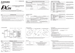
1
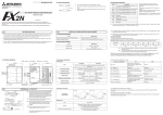
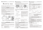
3 (1) Buffer Memory BFM #0: Thermocouple type K or J selection mode INSTALLATION NOTES AND USAGE BFM #0 is used to select K or J type thermocouples for each channel. Each digit of a 4 digit hexadecimal number corresponds to one channel, the least significant digit being channel 1. 3.1 Environmental specification Item FX2N-4AD-TC SPECIAL FUNCTION BLOCK [ Example ] H 3 3 1 0 Specification Environmental specifications (excluding following) Same as those for the FX2N base unit Dielectric withstand voltage 500VAC, 1min (between all terminals and ground) • 3.2 Power supply specification USER’S GUIDE Item Specification Analog circuits 24V DC ±10%, 60mA Digital circuits 5V DC, 40mA (internal power supply from base unit 240ms (conversion time per channel) × 2channels (number of channels being used) = 480ms (total conversion time) JY992D65501A This manual contains text, diagrams and explanations which will guide the reader in the correct installation and operation of the FX2N-4AD-TC special function block and should be read and understood before attempting to install or use the unit. Further information can be found in the FX PROGRAMMING MANUAL and FX2N SERIES HARDWARE MANUAL . 1 • INTRODUCTION All data transfers and parameter settings are adjusted through software control of the FX2N-4AD-TC ; by use of the TO/FROM applied instructions in the FX2N PC. • The FX2N-4AD-TC occupies 8 points of I/O on the FX2N expansion bus. The 8 points can be allocated from either inputs or outputs. The FX2N-4AD-TC draws 40mA from the 5V rail of the FX2N base unit or powered extension unit. • (2) Buffer Memory BFMs #1 to #4: Number of temperature readings to be averaged When the number of temperature readings to be averaged is specified for BFMs #1 to #4, the averaged data is stored in BFMs #5 to #8 (°C) and #13 to #16 (°F). Only the range 1 to 256 is valid for the number of temperature readings to be averaged. If a value outside of this range is input, the default value of 8 is used. (3) Buffer Memory BFMs #9 to #12 and #17 to #20: Present temperature These BFMs store the present value of the input data. This value is stored in units of 0.1°C or 0.1°F, but the resolution is only 0.4°C or 0.72°F for type K and 0.3°C or 0.54°F for type J. 3.3 Performance specification 3.5 Status Information Analog Inputs (1) Buffer Memory BFM #28: Digital range error latch The FX2N-4AD-TC analog block amplifies the signal from four thermocouple sensors (type K or J) and converts the data into 12 bit reading’s stored in the FX2N base unit. Both Centigrade (°C) and Fahrenheit (°F) can be read. Reading resolution is 0.4°C/0.72°F of type K and 0.3°C/0.54°F of type J. • CH1 0 = K type CH2 1 = J type CH3 3 = Not used CH4 A/D conversion time is 240ms per channel. When “3" (not used) is set for a channel, A/D conversion is not executed for that channel and so the total conversion time is decreased. In the above example, the conversion time is as follows: Centigrade (°C) Item BFM #29 b10(digital range error) is used to judge whether the measured temperature is within the unit’s range or not. BFM #28 latches the error status of each channel and can be used to check for thermocouple disconnection. Fahrenheit (°F) Both °C and °F are available by reading the appropriate buffer memory (BFM). Input signal Thermocouple: type K or J (either can be used for each channel), 4 channels, JIS 1602-1981 Rated temprature range Type K -100°C to +1,200°C Type K -148°F to +2,192°F Type J -100°C to +600°C Type J -148°F to +1,112°F b15 or b8 Not used Digital output Resolution Overall accuracy Calibration point Conversion speed Type K -1,000 to 12,000 Type K -1,480 to 21,920 Type J -1,000 to 6,000 Type J -1,480 to 11,120 Type K 0.4°C Type K 0.72°F Type J 0.3°C Type J 0.54°F b6 b5 b4 b3 b2 b1 b0 Low High Low High Low High Low CH4 12 bit conversion stored in 16 bit 2’s complement form Thermocouples with the following specifications can be used: Type K (JIS 1602-1981) Type J (JIS 1602-1981) b7 High CH3 CH2 CH1 Low : Latches ON when temperature measurement data goes below the lowest temperature measurement limit. High : Turns ON when temperature measurement data goes above the highest temperature measurement limit, or when a thermocouple is disconnected. When an error occurs the temperature data before the error is latched. If the measured value returns to within valid limits the temperature data returns to normal operation. (Note: The error remains latched in (BFM #28)) An error can be cleared by writing K0 to BFM #28 using the TO instruction or turning off the power. ± (0.5% full scall +1°C) Freezing point of pure water 0°C / 32°F (240ms ± 2%) × 4 channels (unused channels are not converted) Note : Earth-tipped thermocouples are not suitable for use with this unit. 1.1 EXTERNAL DIMENSIONS Weight: Approx. 0.3 kg (0.66 lbs) Dimensions: mm (inches) Accessories: Self adhesive labels for special function block number identification. 55(2.17) 55(2.17) 4(0.16) 87(3.43) Mounting holes 4.5mm(0.18) dia. 2 4(0.16) FX2N-4AD-TC Extension cable and connector 9(0.35) L- SLD LL+ L+ CH4 24V A/D 24V LED A/D LED 1 shielded SLD CH1 L+ L- Thermocouple 1 shielded CH4 L+ LSLD 2 24VDC±10% 50mA 4 Class 3 Grounding (100 Wor less) 3 3KW 3KW DC/DC 24- converter Extension cable CH4 Temperature compensation circuit 24+ PC CH1 +15V AG -15V FX2N-4AD-TC Analog Input Block (Type K) +21,920 (Type J) +6,000 (Type J) +11,120 b0 : Error +600°C (Type J) +1,200°C (Type K) -1,480 +1,112°F (Type J) +2,192°F (Type K) Item Specification Isolation Photo-coupler isolation between analog and digital circuits. DC/DC converter isolation of power from FX2N base unit. No isolation between analog channels. Number of occupied I/O points ON OFF When either b2 or b3 is ON A/D conversion is stopped for the error channel No error b2 : Power source 24VDC power supply failure power supply normal b3 : Hardware error A/D converter or other hardware failure Hardware Normal b4 to b9 : Not used b10 : Digital range error Digital output/analog input value is outside the specified range. Digital output value is normal. b11 : Averaging number error Selected number of averaged results is outside the available range -see BFM #1 to #4 Averaging is normal. (between 1 to 256) b1 : Not used -148°F -100°C -1,000 Bit devices of BFM #29 8 points taken from the FX2N expansion bus (can be either inputs or outputs) b12 to b15 : Not used (3) Identification Code Buffer Memory BFM #30 The identification code or ID number for a Special Block is read from buffer memory BFM #30 using the FROM command. This number for the FX2N-4AD-TC unit is K2030. The programmable controller can use this facility in its program to identify the special block before commencing data transfer to and from the special block. Terminal screws M3 (0.12) TERMINAL LAYOUTS Thermocouple (Type K) +12,000 Miscellaneous SLD L- SLD L+ CH2 CH3 90(3.54) 80(3.15) POWER Conversion Characteristics Readings given at calibration reference point 0°C/32°F (0/320) respectively. (subject to the overall accuracy) 24- SLD L24+ L+ CH1 24- SLD L24+ L+ CH1 DIN rail mounting slot 35mm(1.38) (2) Buffer Memory BFM #29: Error status Analog Inputs continued... *1: The compensating cables that can be used for connecting with the thermocouple are the following. Type K: KX-G, KX-GS, KX-H, KX-HS,WX-G,WX-H,VX-G Type J: JX-G, JX-H For every 10Ω of line resistance, the compensating cable will indicate a temperature 0.12°C higher than actual. Check the line resistance before using. Long compensating cables are more prone to noise interference, therefore a short (less than 100m) compensating cable is recommended. Unused channels should have a wire link connected between their + and - terminals to prevent an error being detected on that channel. 3.4 Buffer memory assignment BFM CONTENTS *#0 Thermocouuple type K or J selection mode. At shipment: H0000 *#1-#4 CH1 to CH4 Averaged temperature reading to be averaged (1 to 256) Default = 8 #5-#8 CH1 to CH4 Averaged temprature in 0.1°C units #9-#12 CH1 to CH4 Present temprature in 0.1°C units #13-#16 CH1 to CH4 Averaged temprature in 0.1°F units #17-#20 CH1 to CH4 Present temprature in 0.1°F units #21-#27 Reserved *#28 Digital range error latch *3: Connect the ground terminals of the FX2N-4AD-TC unit and the base unit. Use class 3 grounding on the base unit. #29 Error status #30 Identification code K2030 *4: The 24V DC built-in supply of the programmable controller may be used as the power supply. #31 Reserved *2: If there is excessive electrical noise, connect the SLD terminal to the ground terminal on the unit. 3.6 Installation location The FX2N-4AD-TC communicates with the programmable controller through use of buffer memories. BFMs #21 to #27 and #31 are reserved. All non reserved BFMs can be read by the programmable controller using the FROM command. BFMs (buffer memories) marked with an “*” can be written to, from the programmable controller using the TO command. This unit measures temperature according to the temperature difference between the temperature measurement part (themocouple) and the terminal block. If this unit is installed in a place where the temperature of the terminal block varies rapidly, a measuring error may occur. For this reason, the unit should be installed in a place free from excessive temperature variation. 3.7 Using crimp terminations less than 6.2mm(0.24") Use M3(0.12") less than 6.2mm(0.24") • • • Use crimp terminations of the type indicated on the left. Secure the termination using a tightening torque of between 5 and 8 kg⋅cm. Wire only to the module terminals discussed in this manual. Leave all others vacant. 3 (1) Buffer Memory BFM #0: Thermocouple type K or J selection mode INSTALLATION NOTES AND USAGE BFM #0 is used to select K or J type thermocouples for each channel. Each digit of a 4 digit hexadecimal number corresponds to one channel, the least significant digit being channel 1. 3.1 Environmental specification Item FX2N-4AD-TC SPECIAL FUNCTION BLOCK [ Example ] H 3 3 1 0 Specification Environmental specifications (excluding following) Same as those for the FX2N base unit Dielectric withstand voltage 500VAC, 1min (between all terminals and ground) • 3.2 Power supply specification USER’S GUIDE Item Specification Analog circuits 24V DC ±10%, 60mA Digital circuits 5V DC, 40mA (internal power supply from base unit 240ms (conversion time per channel) × 2channels (number of channels being used) = 480ms (total conversion time) JY992D65501A This manual contains text, diagrams and explanations which will guide the reader in the correct installation and operation of the FX2N-4AD-TC special function block and should be read and understood before attempting to install or use the unit. Further information can be found in the FX PROGRAMMING MANUAL and FX2N SERIES HARDWARE MANUAL . 1 • INTRODUCTION All data transfers and parameter settings are adjusted through software control of the FX2N-4AD-TC ; by use of the TO/FROM applied instructions in the FX2N PC. • The FX2N-4AD-TC occupies 8 points of I/O on the FX2N expansion bus. The 8 points can be allocated from either inputs or outputs. The FX2N-4AD-TC draws 40mA from the 5V rail of the FX2N base unit or powered extension unit. • (2) Buffer Memory BFMs #1 to #4: Number of temperature readings to be averaged When the number of temperature readings to be averaged is specified for BFMs #1 to #4, the averaged data is stored in BFMs #5 to #8 (°C) and #13 to #16 (°F). Only the range 1 to 256 is valid for the number of temperature readings to be averaged. If a value outside of this range is input, the default value of 8 is used. (3) Buffer Memory BFMs #9 to #12 and #17 to #20: Present temperature These BFMs store the present value of the input data. This value is stored in units of 0.1°C or 0.1°F, but the resolution is only 0.4°C or 0.72°F for type K and 0.3°C or 0.54°F for type J. 3.3 Performance specification 3.5 Status Information Analog Inputs (1) Buffer Memory BFM #28: Digital range error latch The FX2N-4AD-TC analog block amplifies the signal from four thermocouple sensors (type K or J) and converts the data into 12 bit reading’s stored in the FX2N base unit. Both Centigrade (°C) and Fahrenheit (°F) can be read. Reading resolution is 0.4°C/0.72°F of type K and 0.3°C/0.54°F of type J. • CH1 0 = K type CH2 1 = J type CH3 3 = Not used CH4 A/D conversion time is 240ms per channel. When “3" (not used) is set for a channel, A/D conversion is not executed for that channel and so the total conversion time is decreased. In the above example, the conversion time is as follows: Centigrade (°C) Item BFM #29 b10(digital range error) is used to judge whether the measured temperature is within the unit’s range or not. BFM #28 latches the error status of each channel and can be used to check for thermocouple disconnection. Fahrenheit (°F) Both °C and °F are available by reading the appropriate buffer memory (BFM). Input signal Thermocouple: type K or J (either can be used for each channel), 4 channels, JIS 1602-1981 Rated temprature range Type K -100°C to +1,200°C Type K -148°F to +2,192°F Type J -100°C to +600°C Type J -148°F to +1,112°F b15 or b8 Not used Digital output Resolution Overall accuracy Calibration point Conversion speed Type K -1,000 to 12,000 Type K -1,480 to 21,920 Type J -1,000 to 6,000 Type J -1,480 to 11,120 Type K 0.4°C Type K 0.72°F Type J 0.3°C Type J 0.54°F b6 b5 b4 b3 b2 b1 b0 Low High Low High Low High Low CH4 12 bit conversion stored in 16 bit 2’s complement form Thermocouples with the following specifications can be used: Type K (JIS 1602-1981) Type J (JIS 1602-1981) b7 High CH3 CH2 CH1 Low : Latches ON when temperature measurement data goes below the lowest temperature measurement limit. High : Turns ON when temperature measurement data goes above the highest temperature measurement limit, or when a thermocouple is disconnected. When an error occurs the temperature data before the error is latched. If the measured value returns to within valid limits the temperature data returns to normal operation. (Note: The error remains latched in (BFM #28)) An error can be cleared by writing K0 to BFM #28 using the TO instruction or turning off the power. ± (0.5% full scall +1°C) Freezing point of pure water 0°C / 32°F (240ms ± 2%) × 4 channels (unused channels are not converted) Note : Earth-tipped thermocouples are not suitable for use with this unit. 1.1 EXTERNAL DIMENSIONS Weight: Approx. 0.3 kg (0.66 lbs) Dimensions: mm (inches) Accessories: Self adhesive labels for special function block number identification. 55(2.17) 55(2.17) 4(0.16) 87(3.43) Mounting holes 4.5mm(0.18) dia. 2 4(0.16) FX2N-4AD-TC Extension cable and connector 9(0.35) L- SLD LL+ L+ CH4 24V A/D 24V LED A/D LED 1 shielded SLD CH1 L+ L- Thermocouple 1 shielded CH4 L+ LSLD 2 24VDC±10% 50mA 4 Class 3 Grounding (100 Wor less) 3 3KW 3KW DC/DC 24- converter Extension cable CH4 Temperature compensation circuit 24+ PC CH1 +15V AG -15V FX2N-4AD-TC Analog Input Block (Type K) +21,920 (Type J) +6,000 (Type J) +11,120 b0 : Error +600°C (Type J) +1,200°C (Type K) -1,480 +1,112°F (Type J) +2,192°F (Type K) Item Specification Isolation Photo-coupler isolation between analog and digital circuits. DC/DC converter isolation of power from FX2N base unit. No isolation between analog channels. Number of occupied I/O points ON OFF When either b2 or b3 is ON A/D conversion is stopped for the error channel No error b2 : Power source 24VDC power supply failure power supply normal b3 : Hardware error A/D converter or other hardware failure Hardware Normal b4 to b9 : Not used b10 : Digital range error Digital output/analog input value is outside the specified range. Digital output value is normal. b11 : Averaging number error Selected number of averaged results is outside the available range -see BFM #1 to #4 Averaging is normal. (between 1 to 256) b1 : Not used -148°F -100°C -1,000 Bit devices of BFM #29 8 points taken from the FX2N expansion bus (can be either inputs or outputs) b12 to b15 : Not used (3) Identification Code Buffer Memory BFM #30 The identification code or ID number for a Special Block is read from buffer memory BFM #30 using the FROM command. This number for the FX2N-4AD-TC unit is K2030. The programmable controller can use this facility in its program to identify the special block before commencing data transfer to and from the special block. Terminal screws M3 (0.12) TERMINAL LAYOUTS Thermocouple (Type K) +12,000 Miscellaneous SLD L- SLD L+ CH2 CH3 90(3.54) 80(3.15) POWER Conversion Characteristics Readings given at calibration reference point 0°C/32°F (0/320) respectively. (subject to the overall accuracy) 24- SLD L24+ L+ CH1 24- SLD L24+ L+ CH1 DIN rail mounting slot 35mm(1.38) (2) Buffer Memory BFM #29: Error status Analog Inputs continued... *1: The compensating cables that can be used for connecting with the thermocouple are the following. Type K: KX-G, KX-GS, KX-H, KX-HS,WX-G,WX-H,VX-G Type J: JX-G, JX-H For every 10Ω of line resistance, the compensating cable will indicate a temperature 0.12°C higher than actual. Check the line resistance before using. Long compensating cables are more prone to noise interference, therefore a short (less than 100m) compensating cable is recommended. Unused channels should have a wire link connected between their + and - terminals to prevent an error being detected on that channel. 3.4 Buffer memory assignment BFM CONTENTS *#0 Thermocouuple type K or J selection mode. At shipment: H0000 *#1-#4 CH1 to CH4 Averaged temperature reading to be averaged (1 to 256) Default = 8 #5-#8 CH1 to CH4 Averaged temprature in 0.1°C units #9-#12 CH1 to CH4 Present temprature in 0.1°C units #13-#16 CH1 to CH4 Averaged temprature in 0.1°F units #17-#20 CH1 to CH4 Present temprature in 0.1°F units #21-#27 Reserved *#28 Digital range error latch *3: Connect the ground terminals of the FX2N-4AD-TC unit and the base unit. Use class 3 grounding on the base unit. #29 Error status #30 Identification code K2030 *4: The 24V DC built-in supply of the programmable controller may be used as the power supply. #31 Reserved *2: If there is excessive electrical noise, connect the SLD terminal to the ground terminal on the unit. 3.6 Installation location The FX2N-4AD-TC communicates with the programmable controller through use of buffer memories. BFMs #21 to #27 and #31 are reserved. All non reserved BFMs can be read by the programmable controller using the FROM command. BFMs (buffer memories) marked with an “*” can be written to, from the programmable controller using the TO command. This unit measures temperature according to the temperature difference between the temperature measurement part (themocouple) and the terminal block. If this unit is installed in a place where the temperature of the terminal block varies rapidly, a measuring error may occur. For this reason, the unit should be installed in a place free from excessive temperature variation. 3.7 Using crimp terminations less than 6.2mm(0.24") Use M3(0.12") less than 6.2mm(0.24") • • • Use crimp terminations of the type indicated on the left. Secure the termination using a tightening torque of between 5 and 8 kg⋅cm. Wire only to the module terminals discussed in this manual. Leave all others vacant. 3 (1) Buffer Memory BFM #0: Thermocouple type K or J selection mode INSTALLATION NOTES AND USAGE BFM #0 is used to select K or J type thermocouples for each channel. Each digit of a 4 digit hexadecimal number corresponds to one channel, the least significant digit being channel 1. 3.1 Environmental specification Item FX2N-4AD-TC SPECIAL FUNCTION BLOCK [ Example ] H 3 3 1 0 Specification Environmental specifications (excluding following) Same as those for the FX2N base unit Dielectric withstand voltage 500VAC, 1min (between all terminals and ground) • 3.2 Power supply specification USER’S GUIDE Item Specification Analog circuits 24V DC ±10%, 60mA Digital circuits 5V DC, 40mA (internal power supply from base unit 240ms (conversion time per channel) × 2channels (number of channels being used) = 480ms (total conversion time) JY992D65501A This manual contains text, diagrams and explanations which will guide the reader in the correct installation and operation of the FX2N-4AD-TC special function block and should be read and understood before attempting to install or use the unit. Further information can be found in the FX PROGRAMMING MANUAL and FX2N SERIES HARDWARE MANUAL . 1 • INTRODUCTION All data transfers and parameter settings are adjusted through software control of the FX2N-4AD-TC ; by use of the TO/FROM applied instructions in the FX2N PC. • The FX2N-4AD-TC occupies 8 points of I/O on the FX2N expansion bus. The 8 points can be allocated from either inputs or outputs. The FX2N-4AD-TC draws 40mA from the 5V rail of the FX2N base unit or powered extension unit. • (2) Buffer Memory BFMs #1 to #4: Number of temperature readings to be averaged When the number of temperature readings to be averaged is specified for BFMs #1 to #4, the averaged data is stored in BFMs #5 to #8 (°C) and #13 to #16 (°F). Only the range 1 to 256 is valid for the number of temperature readings to be averaged. If a value outside of this range is input, the default value of 8 is used. (3) Buffer Memory BFMs #9 to #12 and #17 to #20: Present temperature These BFMs store the present value of the input data. This value is stored in units of 0.1°C or 0.1°F, but the resolution is only 0.4°C or 0.72°F for type K and 0.3°C or 0.54°F for type J. 3.3 Performance specification 3.5 Status Information Analog Inputs (1) Buffer Memory BFM #28: Digital range error latch The FX2N-4AD-TC analog block amplifies the signal from four thermocouple sensors (type K or J) and converts the data into 12 bit reading’s stored in the FX2N base unit. Both Centigrade (°C) and Fahrenheit (°F) can be read. Reading resolution is 0.4°C/0.72°F of type K and 0.3°C/0.54°F of type J. • CH1 0 = K type CH2 1 = J type CH3 3 = Not used CH4 A/D conversion time is 240ms per channel. When “3" (not used) is set for a channel, A/D conversion is not executed for that channel and so the total conversion time is decreased. In the above example, the conversion time is as follows: Centigrade (°C) Item BFM #29 b10(digital range error) is used to judge whether the measured temperature is within the unit’s range or not. BFM #28 latches the error status of each channel and can be used to check for thermocouple disconnection. Fahrenheit (°F) Both °C and °F are available by reading the appropriate buffer memory (BFM). Input signal Thermocouple: type K or J (either can be used for each channel), 4 channels, JIS 1602-1981 Rated temprature range Type K -100°C to +1,200°C Type K -148°F to +2,192°F Type J -100°C to +600°C Type J -148°F to +1,112°F b15 or b8 Not used Digital output Resolution Overall accuracy Calibration point Conversion speed Type K -1,000 to 12,000 Type K -1,480 to 21,920 Type J -1,000 to 6,000 Type J -1,480 to 11,120 Type K 0.4°C Type K 0.72°F Type J 0.3°C Type J 0.54°F b6 b5 b4 b3 b2 b1 b0 Low High Low High Low High Low CH4 12 bit conversion stored in 16 bit 2’s complement form Thermocouples with the following specifications can be used: Type K (JIS 1602-1981) Type J (JIS 1602-1981) b7 High CH3 CH2 CH1 Low : Latches ON when temperature measurement data goes below the lowest temperature measurement limit. High : Turns ON when temperature measurement data goes above the highest temperature measurement limit, or when a thermocouple is disconnected. When an error occurs the temperature data before the error is latched. If the measured value returns to within valid limits the temperature data returns to normal operation. (Note: The error remains latched in (BFM #28)) An error can be cleared by writing K0 to BFM #28 using the TO instruction or turning off the power. ± (0.5% full scall +1°C) Freezing point of pure water 0°C / 32°F (240ms ± 2%) × 4 channels (unused channels are not converted) Note : Earth-tipped thermocouples are not suitable for use with this unit. 1.1 EXTERNAL DIMENSIONS Weight: Approx. 0.3 kg (0.66 lbs) Dimensions: mm (inches) Accessories: Self adhesive labels for special function block number identification. 55(2.17) 55(2.17) 4(0.16) 87(3.43) Mounting holes 4.5mm(0.18) dia. 2 4(0.16) FX2N-4AD-TC Extension cable and connector 9(0.35) L- SLD LL+ L+ CH4 24V A/D 24V LED A/D LED 1 shielded SLD CH1 L+ L- Thermocouple 1 shielded CH4 L+ LSLD 2 24VDC±10% 50mA 4 Class 3 Grounding (100 Wor less) 3 3KW 3KW DC/DC 24- converter Extension cable CH4 Temperature compensation circuit 24+ PC CH1 +15V AG -15V FX2N-4AD-TC Analog Input Block (Type K) +21,920 (Type J) +6,000 (Type J) +11,120 b0 : Error +600°C (Type J) +1,200°C (Type K) -1,480 +1,112°F (Type J) +2,192°F (Type K) Item Specification Isolation Photo-coupler isolation between analog and digital circuits. DC/DC converter isolation of power from FX2N base unit. No isolation between analog channels. Number of occupied I/O points ON OFF When either b2 or b3 is ON A/D conversion is stopped for the error channel No error b2 : Power source 24VDC power supply failure power supply normal b3 : Hardware error A/D converter or other hardware failure Hardware Normal b4 to b9 : Not used b10 : Digital range error Digital output/analog input value is outside the specified range. Digital output value is normal. b11 : Averaging number error Selected number of averaged results is outside the available range -see BFM #1 to #4 Averaging is normal. (between 1 to 256) b1 : Not used -148°F -100°C -1,000 Bit devices of BFM #29 8 points taken from the FX2N expansion bus (can be either inputs or outputs) b12 to b15 : Not used (3) Identification Code Buffer Memory BFM #30 The identification code or ID number for a Special Block is read from buffer memory BFM #30 using the FROM command. This number for the FX2N-4AD-TC unit is K2030. The programmable controller can use this facility in its program to identify the special block before commencing data transfer to and from the special block. Terminal screws M3 (0.12) TERMINAL LAYOUTS Thermocouple (Type K) +12,000 Miscellaneous SLD L- SLD L+ CH2 CH3 90(3.54) 80(3.15) POWER Conversion Characteristics Readings given at calibration reference point 0°C/32°F (0/320) respectively. (subject to the overall accuracy) 24- SLD L24+ L+ CH1 24- SLD L24+ L+ CH1 DIN rail mounting slot 35mm(1.38) (2) Buffer Memory BFM #29: Error status Analog Inputs continued... *1: The compensating cables that can be used for connecting with the thermocouple are the following. Type K: KX-G, KX-GS, KX-H, KX-HS,WX-G,WX-H,VX-G Type J: JX-G, JX-H For every 10Ω of line resistance, the compensating cable will indicate a temperature 0.12°C higher than actual. Check the line resistance before using. Long compensating cables are more prone to noise interference, therefore a short (less than 100m) compensating cable is recommended. Unused channels should have a wire link connected between their + and - terminals to prevent an error being detected on that channel. 3.4 Buffer memory assignment BFM CONTENTS *#0 Thermocouuple type K or J selection mode. At shipment: H0000 *#1-#4 CH1 to CH4 Averaged temperature reading to be averaged (1 to 256) Default = 8 #5-#8 CH1 to CH4 Averaged temprature in 0.1°C units #9-#12 CH1 to CH4 Present temprature in 0.1°C units #13-#16 CH1 to CH4 Averaged temprature in 0.1°F units #17-#20 CH1 to CH4 Present temprature in 0.1°F units #21-#27 Reserved *#28 Digital range error latch *3: Connect the ground terminals of the FX2N-4AD-TC unit and the base unit. Use class 3 grounding on the base unit. #29 Error status #30 Identification code K2030 *4: The 24V DC built-in supply of the programmable controller may be used as the power supply. #31 Reserved *2: If there is excessive electrical noise, connect the SLD terminal to the ground terminal on the unit. 3.6 Installation location The FX2N-4AD-TC communicates with the programmable controller through use of buffer memories. BFMs #21 to #27 and #31 are reserved. All non reserved BFMs can be read by the programmable controller using the FROM command. BFMs (buffer memories) marked with an “*” can be written to, from the programmable controller using the TO command. This unit measures temperature according to the temperature difference between the temperature measurement part (themocouple) and the terminal block. If this unit is installed in a place where the temperature of the terminal block varies rapidly, a measuring error may occur. For this reason, the unit should be installed in a place free from excessive temperature variation. 3.7 Using crimp terminations less than 6.2mm(0.24") Use M3(0.12") less than 6.2mm(0.24") • • • Use crimp terminations of the type indicated on the left. Secure the termination using a tightening torque of between 5 and 8 kg⋅cm. Wire only to the module terminals discussed in this manual. Leave all others vacant. 4 6 SYSTEM BLOCK DIAGRAM DIAGNOSTICS 6.1 _Preliminary checks POWER 5V Power LED Supply FX2N series Command information write and data status read Gain and offset values are stored in EEPROM Buffer Memory RAM TO Analog Input CH1 Converted data System ROM DC24V Power Source ±15V 24V LED FX2N-4AD-TC Analog Block 5 CH3 converter Control signals DC/DC converter CH2 A/D 5V A/D LED Cyclic switching Noncontact analog switch Initial Pulse EXAMPLE PROGRAM M8002 Initial Pulse FNC79 TO K2 K0 H3310 K1 FNC78 FROM K2 K30 D2 K1 FNC10 CMP K2030 D2 Specify the type of thermocouple. H3310 → Block No.2 BFM#0 CH4 and CH3: not used CH2: type J(1) CH1: type K(0) Block No.2 BFM #30 → (D2) Identification code M0 II. Check that the FX2N system configuration rules have not been broken, i.e. the number of special function blocks does not exceed 8 and the total system I/O is equal or less than 256, I/O. IV. Check that there is no power overload on either the 5V or 24V power sources, remember the loading on the FX2N base unit or a powered extension unit varies according to the number of extension blocks or special function blocks connected. V. Put the FX2N base unit into RUN. CH4 In the program shown below, the FX2N-4AD-TC occupies the position of special block number 2 ( that is the third closest block to the programmable controller). A type K thermocouple is used on CH1 and a type J on CH2. CH3 and CH4 are not used. The averaging count is four. The averaged values in degrees C of input channels CH1 and CH2 are stored respectively in data registers D0 and D1. M8002 Check whether the input/output wiring and/or extension cables are properly connected on FX2N-4AD-TC analog special function block III. Ensure that the correct operating range has been selected for the application. Photocoupler CPU FROM I. 6.2 Error checking If the FX2N-4AD-TC special function blcok does not seem to operate normally, check the following items. • Check the status of the POWER LED. Lit : The extension cable is properly connected. Otherwise : Check the connection of the extension cable. • • Check the external wiring. • Check the status fo the “A/D” LED (top right corner of the FX2N-4AD-TC). Lit : A/D conversion is proceeding normally. Otherwise : Check buffer memory #29 (error status). If any bits (b0, b2, b3) are ON, then this is why the A/D LED is OFF. Check the status fo the “24V” LED (top right corner of the FX2N-4AD-TC). Lit : FX2N-4AD-TC is ON, 24VDC power source is ON. Otherwise : Possible 24VDC power failure, if ON possible FX2N-4AD-TC failure. When (K2030) = (D2), M1 = ON. i.e. When identification code is K2030, M1 = ON. This initial step checks that the special function block placed at position 2 is actually an FX2N-4AD-TC, i.e. its unit identification number is 2030 (BFM #30). This step is optional, but it provides a software check that the system has been configured correctly. M8000 RUN monitor FNC78 FROM K2 Block No.2 BFM #29 → (K4M10) Transfer the error status to (M25 to M10). When error is found, M10 = ON K29 K4M10 K1 M10 Represents b0 BFM #29 M3 Error found 6.3 Checking special function block numbers Other special units of blocks that use FROM/TO commands, such as analog input blocks, analog output blocks and high-speed counter blocks, can be directly connected to the base unit of the FX2N programmable controller or to the right side of other extension blocks or units. Each special block is consecutively numbered from 0 to 7 beginning from the one closest to the base unit. A maximum of eight special blocks can be connected. This step provides optional monitoring of the FX2N-4AD-TC Error Buffer Memory (#29). If there is an Error on the FX2N-4AD-TC, bit b0 of BFM #29 will be set on. This can be read by this program step, and output as a bit device in the FX2N programmable controller (M3 in this example). Additional Error devices can be output in a similar manner, e.g. b10 BFM #29 Digital range error. (see below) L X2 COM X0 24+ X1 N X4 X5 X6 X7 X10 IN X14 X16 X20 X22 X24 X13 X15 X17 X21 X23 X25 L POWER 0 1 2 3 4 5 6 7 20 21 22 23 24 25 26 27 10 11 12 13 14 15 16 17 K2 K29 K4M10 FNC78 FROM K2 K2 K1 K5 K4 Y2 Y3 Y4 Y6 COM2 Y5 Y7 Y10 COM3 16 17 Y13 Y14 COM4 Y15 D0 M3 Represents b0 BFM #29 M4 Represents b10 BFM #29 (K4) → (BFM #1), (K4) → (BFM #2) Number of samples is changed to four on both CH1 and CH2. (BFM #5) → (D0), (BFM #6) → (D1) Transfer the averaged temperature value in °C to the data registers. K2 This step is the actual reading of the FX2N-4AD-TC input channels. It is essentially the only program step which is needed. The “TO” instruction in this example, sets the input channels, CH1 and CH2, to take the average reading of four samples. The “FROM” instruction reads the average temperatures (BFM #5 and #6) for input channels CH1 and CH2 of the FX2N-4AD-TC. If direct temperature readings are required BFM #9 and #10 should be read instead, e.g. FNC78 FROM K2 2 3 4 5 6 POWER 7 POWER CPU.E OUT 0 FX2N-4AD FX2N-4DA 1 2 3 4 5 6 7 10 11 12 13 14 15 16 17 Y20 Y22 Y24 Y26 COM5 Y21 Y23 Y25 Y27 FX 2N -48MR-ES/UL K2 1 Y0 Y2 COM1 Y1 Y3 Y4 Y6 COM2 Y5 Y7 Y12 Y10 COM3 Y11 Y13 Y14 Y16 COM4 Y15 Y17 D/A 24V 24V A/D K1 X000-X027 Y000-Y027 M20 FNC79 TO P 0 T.V M10 M1 IN 10 11 12 13 14 15 16 17 A/D 24V FNC78 FROM X0 COM X2 X4 X6 X10 X12 X14 X16 X5 24+ X1 X3 X7 X11 X13 X15 X17 PROG.E 6 7 20 21 22 23 24 25 26 27 FX2N-48MR-ES/UL Y0 COM1 M8000 N POWER POWER K29 K4M10 K1 FX2N-4AD-TC result special No. of block No.2 BFM number destination words read 7 FX 2N -4AD FX 2N -16EX FX 2N -4DA Special block Special block X030 -X047 No.1 No.0 FX 2N -32ER FX 2N-4AD-TC X050-X067 Y030-Y047 Special block Guidelines for the safety of the user and protection of the FX2N-4AD-TC special function block • This manual has been written to be used by trained and competent personnel. This is defined by the European directives for machinery, low voltage and EMC. • If in doubt at any stage during the installation of the FX2N-24AD-TC always consult a professional electrical engineer who is qualified and trained to the local and national standards. If in doubt about the operation or use of the FX2N-4AD-TC please consult the nearest Mitsubishi Electric distributor. • Under no circumstances will Mitsubishi Electric be liable or responsible for any consequential damage that may arise as a result of the installation or use of this equipment. • All examples and diagrams shown in this manual are intended only as an aid to understanding the text, not to guarantee operation. Mitsubishi Electric will accept no responsibility for actual use of the product based on these illustrative examples. No.2 EMC CONSIDERATIONS Electromagnetic compatibility or EMC must be considered before using the FX2N-4AD-TC. Manual number : JY992D65501 Mitsubishi recommend that the thermocouple sensors used, should be fitted with a form of seild or screening as protection against EMC noise. Manual revision :A Date : JUNE 1997 If some form of cable protection is used, the “Shield” must be terminated at the SLD chapter 2. terminals as shown in Because of the delicate nature of all analog signals, failure to take good EMC precautions could lead to EMC noise induced errors ; up to ±10% of actual values. This is an absolute worst case figure, users who do take good precautions can expect operation within normal tolerances. HEAD OFFICE:MITSUBISHI DENKI BLDG MARUNOUCHI TOKYO 100 TELEX:J24532 CABLE MELCO TOKYO HIMEJI WORKS:840, CHIYODA CHO, HIMEJI, JAPAN EMC considerations should include selection of good quality cables, good routing of those cables away from potential noise sources. Additionally it is recommended that signal averaging is used as this will reduce the effects of random noise “spikes”. JY992D65501A Effective JUN. 1997 Specifications are subject to change without notice 4 6 SYSTEM BLOCK DIAGRAM DIAGNOSTICS 6.1 _Preliminary checks POWER 5V Power LED Supply FX2N series Command information write and data status read Gain and offset values are stored in EEPROM Buffer Memory RAM TO Analog Input CH1 Converted data System ROM DC24V Power Source ±15V 24V LED FX2N-4AD-TC Analog Block 5 CH3 converter Control signals DC/DC converter CH2 A/D 5V A/D LED Cyclic switching Noncontact analog switch Initial Pulse EXAMPLE PROGRAM M8002 Initial Pulse FNC79 TO K2 K0 H3310 K1 FNC78 FROM K2 K30 D2 K1 FNC10 CMP K2030 D2 Specify the type of thermocouple. H3310 → Block No.2 BFM#0 CH4 and CH3: not used CH2: type J(1) CH1: type K(0) Block No.2 BFM #30 → (D2) Identification code M0 II. Check that the FX2N system configuration rules have not been broken, i.e. the number of special function blocks does not exceed 8 and the total system I/O is equal or less than 256, I/O. IV. Check that there is no power overload on either the 5V or 24V power sources, remember the loading on the FX2N base unit or a powered extension unit varies according to the number of extension blocks or special function blocks connected. V. Put the FX2N base unit into RUN. CH4 In the program shown below, the FX2N-4AD-TC occupies the position of special block number 2 ( that is the third closest block to the programmable controller). A type K thermocouple is used on CH1 and a type J on CH2. CH3 and CH4 are not used. The averaging count is four. The averaged values in degrees C of input channels CH1 and CH2 are stored respectively in data registers D0 and D1. M8002 Check whether the input/output wiring and/or extension cables are properly connected on FX2N-4AD-TC analog special function block III. Ensure that the correct operating range has been selected for the application. Photocoupler CPU FROM I. 6.2 Error checking If the FX2N-4AD-TC special function blcok does not seem to operate normally, check the following items. • Check the status of the POWER LED. Lit : The extension cable is properly connected. Otherwise : Check the connection of the extension cable. • • Check the external wiring. • Check the status fo the “A/D” LED (top right corner of the FX2N-4AD-TC). Lit : A/D conversion is proceeding normally. Otherwise : Check buffer memory #29 (error status). If any bits (b0, b2, b3) are ON, then this is why the A/D LED is OFF. Check the status fo the “24V” LED (top right corner of the FX2N-4AD-TC). Lit : FX2N-4AD-TC is ON, 24VDC power source is ON. Otherwise : Possible 24VDC power failure, if ON possible FX2N-4AD-TC failure. When (K2030) = (D2), M1 = ON. i.e. When identification code is K2030, M1 = ON. This initial step checks that the special function block placed at position 2 is actually an FX2N-4AD-TC, i.e. its unit identification number is 2030 (BFM #30). This step is optional, but it provides a software check that the system has been configured correctly. M8000 RUN monitor FNC78 FROM K2 Block No.2 BFM #29 → (K4M10) Transfer the error status to (M25 to M10). When error is found, M10 = ON K29 K4M10 K1 M10 Represents b0 BFM #29 M3 Error found 6.3 Checking special function block numbers Other special units of blocks that use FROM/TO commands, such as analog input blocks, analog output blocks and high-speed counter blocks, can be directly connected to the base unit of the FX2N programmable controller or to the right side of other extension blocks or units. Each special block is consecutively numbered from 0 to 7 beginning from the one closest to the base unit. A maximum of eight special blocks can be connected. This step provides optional monitoring of the FX2N-4AD-TC Error Buffer Memory (#29). If there is an Error on the FX2N-4AD-TC, bit b0 of BFM #29 will be set on. This can be read by this program step, and output as a bit device in the FX2N programmable controller (M3 in this example). Additional Error devices can be output in a similar manner, e.g. b10 BFM #29 Digital range error. (see below) L X2 COM X0 24+ X1 N X4 X5 X6 X7 X10 IN X14 X16 X20 X22 X24 X13 X15 X17 X21 X23 X25 L POWER 0 1 2 3 4 5 6 7 20 21 22 23 24 25 26 27 10 11 12 13 14 15 16 17 K2 K29 K4M10 FNC78 FROM K2 K2 K1 K5 K4 Y2 Y3 Y4 Y6 COM2 Y5 Y7 Y10 COM3 16 17 Y13 Y14 COM4 Y15 D0 M3 Represents b0 BFM #29 M4 Represents b10 BFM #29 (K4) → (BFM #1), (K4) → (BFM #2) Number of samples is changed to four on both CH1 and CH2. (BFM #5) → (D0), (BFM #6) → (D1) Transfer the averaged temperature value in °C to the data registers. K2 This step is the actual reading of the FX2N-4AD-TC input channels. It is essentially the only program step which is needed. The “TO” instruction in this example, sets the input channels, CH1 and CH2, to take the average reading of four samples. The “FROM” instruction reads the average temperatures (BFM #5 and #6) for input channels CH1 and CH2 of the FX2N-4AD-TC. If direct temperature readings are required BFM #9 and #10 should be read instead, e.g. FNC78 FROM K2 2 3 4 5 6 POWER 7 POWER CPU.E OUT 0 FX2N-4AD FX2N-4DA 1 2 3 4 5 6 7 10 11 12 13 14 15 16 17 Y20 Y22 Y24 Y26 COM5 Y21 Y23 Y25 Y27 FX 2N -48MR-ES/UL K2 1 Y0 Y2 COM1 Y1 Y3 Y4 Y6 COM2 Y5 Y7 Y12 Y10 COM3 Y11 Y13 Y14 Y16 COM4 Y15 Y17 D/A 24V 24V A/D K1 X000-X027 Y000-Y027 M20 FNC79 TO P 0 T.V M10 M1 IN 10 11 12 13 14 15 16 17 A/D 24V FNC78 FROM X0 COM X2 X4 X6 X10 X12 X14 X16 X5 24+ X1 X3 X7 X11 X13 X15 X17 PROG.E 6 7 20 21 22 23 24 25 26 27 FX2N-48MR-ES/UL Y0 COM1 M8000 N POWER POWER K29 K4M10 K1 FX2N-4AD-TC result special No. of block No.2 BFM number destination words read 7 FX 2N -4AD FX 2N -16EX FX 2N -4DA Special block Special block X030 -X047 No.1 No.0 FX 2N -32ER FX 2N-4AD-TC X050-X067 Y030-Y047 Special block Guidelines for the safety of the user and protection of the FX2N-4AD-TC special function block • This manual has been written to be used by trained and competent personnel. This is defined by the European directives for machinery, low voltage and EMC. • If in doubt at any stage during the installation of the FX2N-24AD-TC always consult a professional electrical engineer who is qualified and trained to the local and national standards. If in doubt about the operation or use of the FX2N-4AD-TC please consult the nearest Mitsubishi Electric distributor. • Under no circumstances will Mitsubishi Electric be liable or responsible for any consequential damage that may arise as a result of the installation or use of this equipment. • All examples and diagrams shown in this manual are intended only as an aid to understanding the text, not to guarantee operation. Mitsubishi Electric will accept no responsibility for actual use of the product based on these illustrative examples. No.2 EMC CONSIDERATIONS Electromagnetic compatibility or EMC must be considered before using the FX2N-4AD-TC. Manual number : JY992D65501 Mitsubishi recommend that the thermocouple sensors used, should be fitted with a form of seild or screening as protection against EMC noise. Manual revision :A Date : JUNE 1997 If some form of cable protection is used, the “Shield” must be terminated at the SLD chapter 2. terminals as shown in Because of the delicate nature of all analog signals, failure to take good EMC precautions could lead to EMC noise induced errors ; up to ±10% of actual values. This is an absolute worst case figure, users who do take good precautions can expect operation within normal tolerances. HEAD OFFICE:MITSUBISHI DENKI BLDG MARUNOUCHI TOKYO 100 TELEX:J24532 CABLE MELCO TOKYO HIMEJI WORKS:840, CHIYODA CHO, HIMEJI, JAPAN EMC considerations should include selection of good quality cables, good routing of those cables away from potential noise sources. Additionally it is recommended that signal averaging is used as this will reduce the effects of random noise “spikes”. JY992D65501A Effective JUN. 1997 Specifications are subject to change without notice 4 6 SYSTEM BLOCK DIAGRAM DIAGNOSTICS 6.1 _Preliminary checks POWER 5V Power LED Supply FX2N series Command information write and data status read Gain and offset values are stored in EEPROM Buffer Memory RAM TO Analog Input CH1 Converted data System ROM DC24V Power Source ±15V 24V LED FX2N-4AD-TC Analog Block 5 CH3 converter Control signals DC/DC converter CH2 A/D 5V A/D LED Cyclic switching Noncontact analog switch Initial Pulse EXAMPLE PROGRAM M8002 Initial Pulse FNC79 TO K2 K0 H3310 K1 FNC78 FROM K2 K30 D2 K1 FNC10 CMP K2030 D2 Specify the type of thermocouple. H3310 → Block No.2 BFM#0 CH4 and CH3: not used CH2: type J(1) CH1: type K(0) Block No.2 BFM #30 → (D2) Identification code M0 II. Check that the FX2N system configuration rules have not been broken, i.e. the number of special function blocks does not exceed 8 and the total system I/O is equal or less than 256, I/O. IV. Check that there is no power overload on either the 5V or 24V power sources, remember the loading on the FX2N base unit or a powered extension unit varies according to the number of extension blocks or special function blocks connected. V. Put the FX2N base unit into RUN. CH4 In the program shown below, the FX2N-4AD-TC occupies the position of special block number 2 ( that is the third closest block to the programmable controller). A type K thermocouple is used on CH1 and a type J on CH2. CH3 and CH4 are not used. The averaging count is four. The averaged values in degrees C of input channels CH1 and CH2 are stored respectively in data registers D0 and D1. M8002 Check whether the input/output wiring and/or extension cables are properly connected on FX2N-4AD-TC analog special function block III. Ensure that the correct operating range has been selected for the application. Photocoupler CPU FROM I. 6.2 Error checking If the FX2N-4AD-TC special function blcok does not seem to operate normally, check the following items. • Check the status of the POWER LED. Lit : The extension cable is properly connected. Otherwise : Check the connection of the extension cable. • • Check the external wiring. • Check the status fo the “A/D” LED (top right corner of the FX2N-4AD-TC). Lit : A/D conversion is proceeding normally. Otherwise : Check buffer memory #29 (error status). If any bits (b0, b2, b3) are ON, then this is why the A/D LED is OFF. Check the status fo the “24V” LED (top right corner of the FX2N-4AD-TC). Lit : FX2N-4AD-TC is ON, 24VDC power source is ON. Otherwise : Possible 24VDC power failure, if ON possible FX2N-4AD-TC failure. When (K2030) = (D2), M1 = ON. i.e. When identification code is K2030, M1 = ON. This initial step checks that the special function block placed at position 2 is actually an FX2N-4AD-TC, i.e. its unit identification number is 2030 (BFM #30). This step is optional, but it provides a software check that the system has been configured correctly. M8000 RUN monitor FNC78 FROM K2 Block No.2 BFM #29 → (K4M10) Transfer the error status to (M25 to M10). When error is found, M10 = ON K29 K4M10 K1 M10 Represents b0 BFM #29 M3 Error found 6.3 Checking special function block numbers Other special units of blocks that use FROM/TO commands, such as analog input blocks, analog output blocks and high-speed counter blocks, can be directly connected to the base unit of the FX2N programmable controller or to the right side of other extension blocks or units. Each special block is consecutively numbered from 0 to 7 beginning from the one closest to the base unit. A maximum of eight special blocks can be connected. This step provides optional monitoring of the FX2N-4AD-TC Error Buffer Memory (#29). If there is an Error on the FX2N-4AD-TC, bit b0 of BFM #29 will be set on. This can be read by this program step, and output as a bit device in the FX2N programmable controller (M3 in this example). Additional Error devices can be output in a similar manner, e.g. b10 BFM #29 Digital range error. (see below) L X2 COM X0 24+ X1 N X4 X5 X6 X7 X10 IN X14 X16 X20 X22 X24 X13 X15 X17 X21 X23 X25 L POWER 0 1 2 3 4 5 6 7 20 21 22 23 24 25 26 27 10 11 12 13 14 15 16 17 K2 K29 K4M10 FNC78 FROM K2 K2 K1 K5 K4 Y2 Y3 Y4 Y6 COM2 Y5 Y7 Y10 COM3 16 17 Y13 Y14 COM4 Y15 D0 M3 Represents b0 BFM #29 M4 Represents b10 BFM #29 (K4) → (BFM #1), (K4) → (BFM #2) Number of samples is changed to four on both CH1 and CH2. (BFM #5) → (D0), (BFM #6) → (D1) Transfer the averaged temperature value in °C to the data registers. K2 This step is the actual reading of the FX2N-4AD-TC input channels. It is essentially the only program step which is needed. The “TO” instruction in this example, sets the input channels, CH1 and CH2, to take the average reading of four samples. The “FROM” instruction reads the average temperatures (BFM #5 and #6) for input channels CH1 and CH2 of the FX2N-4AD-TC. If direct temperature readings are required BFM #9 and #10 should be read instead, e.g. FNC78 FROM K2 2 3 4 5 6 POWER 7 POWER CPU.E OUT 0 FX2N-4AD FX2N-4DA 1 2 3 4 5 6 7 10 11 12 13 14 15 16 17 Y20 Y22 Y24 Y26 COM5 Y21 Y23 Y25 Y27 FX 2N -48MR-ES/UL K2 1 Y0 Y2 COM1 Y1 Y3 Y4 Y6 COM2 Y5 Y7 Y12 Y10 COM3 Y11 Y13 Y14 Y16 COM4 Y15 Y17 D/A 24V 24V A/D K1 X000-X027 Y000-Y027 M20 FNC79 TO P 0 T.V M10 M1 IN 10 11 12 13 14 15 16 17 A/D 24V FNC78 FROM X0 COM X2 X4 X6 X10 X12 X14 X16 X5 24+ X1 X3 X7 X11 X13 X15 X17 PROG.E 6 7 20 21 22 23 24 25 26 27 FX2N-48MR-ES/UL Y0 COM1 M8000 N POWER POWER K29 K4M10 K1 FX2N-4AD-TC result special No. of block No.2 BFM number destination words read 7 FX 2N -4AD FX 2N -16EX FX 2N -4DA Special block Special block X030 -X047 No.1 No.0 FX 2N -32ER FX 2N-4AD-TC X050-X067 Y030-Y047 Special block Guidelines for the safety of the user and protection of the FX2N-4AD-TC special function block • This manual has been written to be used by trained and competent personnel. This is defined by the European directives for machinery, low voltage and EMC. • If in doubt at any stage during the installation of the FX2N-24AD-TC always consult a professional electrical engineer who is qualified and trained to the local and national standards. If in doubt about the operation or use of the FX2N-4AD-TC please consult the nearest Mitsubishi Electric distributor. • Under no circumstances will Mitsubishi Electric be liable or responsible for any consequential damage that may arise as a result of the installation or use of this equipment. • All examples and diagrams shown in this manual are intended only as an aid to understanding the text, not to guarantee operation. Mitsubishi Electric will accept no responsibility for actual use of the product based on these illustrative examples. No.2 EMC CONSIDERATIONS Electromagnetic compatibility or EMC must be considered before using the FX2N-4AD-TC. Manual number : JY992D65501 Mitsubishi recommend that the thermocouple sensors used, should be fitted with a form of seild or screening as protection against EMC noise. Manual revision :A Date : JUNE 1997 If some form of cable protection is used, the “Shield” must be terminated at the SLD chapter 2. terminals as shown in Because of the delicate nature of all analog signals, failure to take good EMC precautions could lead to EMC noise induced errors ; up to ±10% of actual values. This is an absolute worst case figure, users who do take good precautions can expect operation within normal tolerances. HEAD OFFICE:MITSUBISHI DENKI BLDG MARUNOUCHI TOKYO 100 TELEX:J24532 CABLE MELCO TOKYO HIMEJI WORKS:840, CHIYODA CHO, HIMEJI, JAPAN EMC considerations should include selection of good quality cables, good routing of those cables away from potential noise sources. Additionally it is recommended that signal averaging is used as this will reduce the effects of random noise “spikes”. JY992D65501A Effective JUN. 1997 Specifications are subject to change without notice 3 (1) Buffer Memory BFM #0: Thermocouple type K or J selection mode INSTALLATION NOTES AND USAGE BFM #0 is used to select K or J type thermocouples for each channel. Each digit of a 4 digit hexadecimal number corresponds to one channel, the least significant digit being channel 1. 3.1 Environmental specification Item FX2N-4AD-TC SPECIAL FUNCTION BLOCK [ Example ] H 3 3 1 0 Specification Environmental specifications (excluding following) Same as those for the FX2N base unit Dielectric withstand voltage 500VAC, 1min (between all terminals and ground) • 3.2 Power supply specification USER’S GUIDE Item Specification Analog circuits 24V DC ±10%, 60mA Digital circuits 5V DC, 40mA (internal power supply from base unit 240ms (conversion time per channel) × 2channels (number of channels being used) = 480ms (total conversion time) JY992D65501A This manual contains text, diagrams and explanations which will guide the reader in the correct installation and operation of the FX2N-4AD-TC special function block and should be read and understood before attempting to install or use the unit. Further information can be found in the FX PROGRAMMING MANUAL and FX2N SERIES HARDWARE MANUAL . 1 • INTRODUCTION All data transfers and parameter settings are adjusted through software control of the FX2N-4AD-TC ; by use of the TO/FROM applied instructions in the FX2N PC. • The FX2N-4AD-TC occupies 8 points of I/O on the FX2N expansion bus. The 8 points can be allocated from either inputs or outputs. The FX2N-4AD-TC draws 40mA from the 5V rail of the FX2N base unit or powered extension unit. • (2) Buffer Memory BFMs #1 to #4: Number of temperature readings to be averaged When the number of temperature readings to be averaged is specified for BFMs #1 to #4, the averaged data is stored in BFMs #5 to #8 (°C) and #13 to #16 (°F). Only the range 1 to 256 is valid for the number of temperature readings to be averaged. If a value outside of this range is input, the default value of 8 is used. (3) Buffer Memory BFMs #9 to #12 and #17 to #20: Present temperature These BFMs store the present value of the input data. This value is stored in units of 0.1°C or 0.1°F, but the resolution is only 0.4°C or 0.72°F for type K and 0.3°C or 0.54°F for type J. 3.3 Performance specification 3.5 Status Information Analog Inputs (1) Buffer Memory BFM #28: Digital range error latch The FX2N-4AD-TC analog block amplifies the signal from four thermocouple sensors (type K or J) and converts the data into 12 bit reading’s stored in the FX2N base unit. Both Centigrade (°C) and Fahrenheit (°F) can be read. Reading resolution is 0.4°C/0.72°F of type K and 0.3°C/0.54°F of type J. • CH1 0 = K type CH2 1 = J type CH3 3 = Not used CH4 A/D conversion time is 240ms per channel. When “3" (not used) is set for a channel, A/D conversion is not executed for that channel and so the total conversion time is decreased. In the above example, the conversion time is as follows: Centigrade (°C) Item BFM #29 b10(digital range error) is used to judge whether the measured temperature is within the unit’s range or not. BFM #28 latches the error status of each channel and can be used to check for thermocouple disconnection. Fahrenheit (°F) Both °C and °F are available by reading the appropriate buffer memory (BFM). Input signal Thermocouple: type K or J (either can be used for each channel), 4 channels, JIS 1602-1981 Rated temprature range Type K -100°C to +1,200°C Type K -148°F to +2,192°F Type J -100°C to +600°C Type J -148°F to +1,112°F b15 or b8 Not used Digital output Resolution Overall accuracy Calibration point Conversion speed Type K -1,000 to 12,000 Type K -1,480 to 21,920 Type J -1,000 to 6,000 Type J -1,480 to 11,120 Type K 0.4°C Type K 0.72°F Type J 0.3°C Type J 0.54°F b6 b5 b4 b3 b2 b1 b0 Low High Low High Low High Low CH4 12 bit conversion stored in 16 bit 2’s complement form Thermocouples with the following specifications can be used: Type K (JIS 1602-1981) Type J (JIS 1602-1981) b7 High CH3 CH2 CH1 Low : Latches ON when temperature measurement data goes below the lowest temperature measurement limit. High : Turns ON when temperature measurement data goes above the highest temperature measurement limit, or when a thermocouple is disconnected. When an error occurs the temperature data before the error is latched. If the measured value returns to within valid limits the temperature data returns to normal operation. (Note: The error remains latched in (BFM #28)) An error can be cleared by writing K0 to BFM #28 using the TO instruction or turning off the power. ± (0.5% full scall +1°C) Freezing point of pure water 0°C / 32°F (240ms ± 2%) × 4 channels (unused channels are not converted) Note : Earth-tipped thermocouples are not suitable for use with this unit. 1.1 EXTERNAL DIMENSIONS Weight: Approx. 0.3 kg (0.66 lbs) Dimensions: mm (inches) Accessories: Self adhesive labels for special function block number identification. 55(2.17) 55(2.17) 4(0.16) 87(3.43) Mounting holes 4.5mm(0.18) dia. 2 4(0.16) FX2N-4AD-TC Extension cable and connector 9(0.35) L- SLD LL+ L+ CH4 24V A/D 24V LED A/D LED 1 shielded SLD CH1 L+ L- Thermocouple 1 shielded CH4 L+ LSLD 2 24VDC±10% 50mA 4 Class 3 Grounding (100 Wor less) 3 3KW 3KW DC/DC 24- converter Extension cable CH4 Temperature compensation circuit 24+ PC CH1 +15V AG -15V FX2N-4AD-TC Analog Input Block (Type K) +21,920 (Type J) +6,000 (Type J) +11,120 b0 : Error +600°C (Type J) +1,200°C (Type K) -1,480 +1,112°F (Type J) +2,192°F (Type K) Item Specification Isolation Photo-coupler isolation between analog and digital circuits. DC/DC converter isolation of power from FX2N base unit. No isolation between analog channels. Number of occupied I/O points ON OFF When either b2 or b3 is ON A/D conversion is stopped for the error channel No error b2 : Power source 24VDC power supply failure power supply normal b3 : Hardware error A/D converter or other hardware failure Hardware Normal b4 to b9 : Not used b10 : Digital range error Digital output/analog input value is outside the specified range. Digital output value is normal. b11 : Averaging number error Selected number of averaged results is outside the available range -see BFM #1 to #4 Averaging is normal. (between 1 to 256) b1 : Not used -148°F -100°C -1,000 Bit devices of BFM #29 8 points taken from the FX2N expansion bus (can be either inputs or outputs) b12 to b15 : Not used (3) Identification Code Buffer Memory BFM #30 The identification code or ID number for a Special Block is read from buffer memory BFM #30 using the FROM command. This number for the FX2N-4AD-TC unit is K2030. The programmable controller can use this facility in its program to identify the special block before commencing data transfer to and from the special block. Terminal screws M3 (0.12) TERMINAL LAYOUTS Thermocouple (Type K) +12,000 Miscellaneous SLD L- SLD L+ CH2 CH3 90(3.54) 80(3.15) POWER Conversion Characteristics Readings given at calibration reference point 0°C/32°F (0/320) respectively. (subject to the overall accuracy) 24- SLD L24+ L+ CH1 24- SLD L24+ L+ CH1 DIN rail mounting slot 35mm(1.38) (2) Buffer Memory BFM #29: Error status Analog Inputs continued... *1: The compensating cables that can be used for connecting with the thermocouple are the following. Type K: KX-G, KX-GS, KX-H, KX-HS,WX-G,WX-H,VX-G Type J: JX-G, JX-H For every 10Ω of line resistance, the compensating cable will indicate a temperature 0.12°C higher than actual. Check the line resistance before using. Long compensating cables are more prone to noise interference, therefore a short (less than 100m) compensating cable is recommended. Unused channels should have a wire link connected between their + and - terminals to prevent an error being detected on that channel. 3.4 Buffer memory assignment BFM CONTENTS *#0 Thermocouuple type K or J selection mode. At shipment: H0000 *#1-#4 CH1 to CH4 Averaged temperature reading to be averaged (1 to 256) Default = 8 #5-#8 CH1 to CH4 Averaged temprature in 0.1°C units #9-#12 CH1 to CH4 Present temprature in 0.1°C units #13-#16 CH1 to CH4 Averaged temprature in 0.1°F units #17-#20 CH1 to CH4 Present temprature in 0.1°F units #21-#27 Reserved *#28 Digital range error latch *3: Connect the ground terminals of the FX2N-4AD-TC unit and the base unit. Use class 3 grounding on the base unit. #29 Error status #30 Identification code K2030 *4: The 24V DC built-in supply of the programmable controller may be used as the power supply. #31 Reserved *2: If there is excessive electrical noise, connect the SLD terminal to the ground terminal on the unit. 3.6 Installation location The FX2N-4AD-TC communicates with the programmable controller through use of buffer memories. BFMs #21 to #27 and #31 are reserved. All non reserved BFMs can be read by the programmable controller using the FROM command. BFMs (buffer memories) marked with an “*” can be written to, from the programmable controller using the TO command. This unit measures temperature according to the temperature difference between the temperature measurement part (themocouple) and the terminal block. If this unit is installed in a place where the temperature of the terminal block varies rapidly, a measuring error may occur. For this reason, the unit should be installed in a place free from excessive temperature variation. 3.7 Using crimp terminations less than 6.2mm(0.24") Use M3(0.12") less than 6.2mm(0.24") • • • Use crimp terminations of the type indicated on the left. Secure the termination using a tightening torque of between 5 and 8 kg⋅cm. Wire only to the module terminals discussed in this manual. Leave all others vacant. 4 6 SYSTEM BLOCK DIAGRAM DIAGNOSTICS 6.1 _Preliminary checks POWER 5V Power LED Supply FX2N series Command information write and data status read Gain and offset values are stored in EEPROM Buffer Memory RAM TO Analog Input CH1 Converted data System ROM DC24V Power Source ±15V 24V LED FX2N-4AD-TC Analog Block 5 CH3 converter Control signals DC/DC converter CH2 A/D 5V A/D LED Cyclic switching Noncontact analog switch Initial Pulse EXAMPLE PROGRAM M8002 Initial Pulse FNC79 TO K2 K0 H3310 K1 FNC78 FROM K2 K30 D2 K1 FNC10 CMP K2030 D2 Specify the type of thermocouple. H3310 → Block No.2 BFM#0 CH4 and CH3: not used CH2: type J(1) CH1: type K(0) Block No.2 BFM #30 → (D2) Identification code M0 II. Check that the FX2N system configuration rules have not been broken, i.e. the number of special function blocks does not exceed 8 and the total system I/O is equal or less than 256, I/O. IV. Check that there is no power overload on either the 5V or 24V power sources, remember the loading on the FX2N base unit or a powered extension unit varies according to the number of extension blocks or special function blocks connected. V. Put the FX2N base unit into RUN. CH4 In the program shown below, the FX2N-4AD-TC occupies the position of special block number 2 ( that is the third closest block to the programmable controller). A type K thermocouple is used on CH1 and a type J on CH2. CH3 and CH4 are not used. The averaging count is four. The averaged values in degrees C of input channels CH1 and CH2 are stored respectively in data registers D0 and D1. M8002 Check whether the input/output wiring and/or extension cables are properly connected on FX2N-4AD-TC analog special function block III. Ensure that the correct operating range has been selected for the application. Photocoupler CPU FROM I. 6.2 Error checking If the FX2N-4AD-TC special function blcok does not seem to operate normally, check the following items. • Check the status of the POWER LED. Lit : The extension cable is properly connected. Otherwise : Check the connection of the extension cable. • • Check the external wiring. • Check the status fo the “A/D” LED (top right corner of the FX2N-4AD-TC). Lit : A/D conversion is proceeding normally. Otherwise : Check buffer memory #29 (error status). If any bits (b0, b2, b3) are ON, then this is why the A/D LED is OFF. Check the status fo the “24V” LED (top right corner of the FX2N-4AD-TC). Lit : FX2N-4AD-TC is ON, 24VDC power source is ON. Otherwise : Possible 24VDC power failure, if ON possible FX2N-4AD-TC failure. When (K2030) = (D2), M1 = ON. i.e. When identification code is K2030, M1 = ON. This initial step checks that the special function block placed at position 2 is actually an FX2N-4AD-TC, i.e. its unit identification number is 2030 (BFM #30). This step is optional, but it provides a software check that the system has been configured correctly. M8000 RUN monitor FNC78 FROM K2 Block No.2 BFM #29 → (K4M10) Transfer the error status to (M25 to M10). When error is found, M10 = ON K29 K4M10 K1 M10 Represents b0 BFM #29 M3 Error found 6.3 Checking special function block numbers Other special units of blocks that use FROM/TO commands, such as analog input blocks, analog output blocks and high-speed counter blocks, can be directly connected to the base unit of the FX2N programmable controller or to the right side of other extension blocks or units. Each special block is consecutively numbered from 0 to 7 beginning from the one closest to the base unit. A maximum of eight special blocks can be connected. This step provides optional monitoring of the FX2N-4AD-TC Error Buffer Memory (#29). If there is an Error on the FX2N-4AD-TC, bit b0 of BFM #29 will be set on. This can be read by this program step, and output as a bit device in the FX2N programmable controller (M3 in this example). Additional Error devices can be output in a similar manner, e.g. b10 BFM #29 Digital range error. (see below) L X2 COM X0 24+ X1 N X4 X5 X6 X7 X10 IN X14 X16 X20 X22 X24 X13 X15 X17 X21 X23 X25 L POWER 0 1 2 3 4 5 6 7 20 21 22 23 24 25 26 27 10 11 12 13 14 15 16 17 K2 K29 K4M10 FNC78 FROM K2 K2 K1 K5 K4 Y2 Y3 Y4 Y6 COM2 Y5 Y7 Y10 COM3 16 17 Y13 Y14 COM4 Y15 D0 M3 Represents b0 BFM #29 M4 Represents b10 BFM #29 (K4) → (BFM #1), (K4) → (BFM #2) Number of samples is changed to four on both CH1 and CH2. (BFM #5) → (D0), (BFM #6) → (D1) Transfer the averaged temperature value in °C to the data registers. K2 This step is the actual reading of the FX2N-4AD-TC input channels. It is essentially the only program step which is needed. The “TO” instruction in this example, sets the input channels, CH1 and CH2, to take the average reading of four samples. The “FROM” instruction reads the average temperatures (BFM #5 and #6) for input channels CH1 and CH2 of the FX2N-4AD-TC. If direct temperature readings are required BFM #9 and #10 should be read instead, e.g. FNC78 FROM K2 2 3 4 5 6 POWER 7 POWER CPU.E OUT 0 FX2N-4AD FX2N-4DA 1 2 3 4 5 6 7 10 11 12 13 14 15 16 17 Y20 Y22 Y24 Y26 COM5 Y21 Y23 Y25 Y27 FX 2N -48MR-ES/UL K2 1 Y0 Y2 COM1 Y1 Y3 Y4 Y6 COM2 Y5 Y7 Y12 Y10 COM3 Y11 Y13 Y14 Y16 COM4 Y15 Y17 D/A 24V 24V A/D K1 X000-X027 Y000-Y027 M20 FNC79 TO P 0 T.V M10 M1 IN 10 11 12 13 14 15 16 17 A/D 24V FNC78 FROM X0 COM X2 X4 X6 X10 X12 X14 X16 X5 24+ X1 X3 X7 X11 X13 X15 X17 PROG.E 6 7 20 21 22 23 24 25 26 27 FX2N-48MR-ES/UL Y0 COM1 M8000 N POWER POWER K29 K4M10 K1 FX2N-4AD-TC result special No. of block No.2 BFM number destination words read 7 FX 2N -4AD FX 2N -16EX FX 2N -4DA Special block Special block X030 -X047 No.1 No.0 FX 2N -32ER FX 2N-4AD-TC X050-X067 Y030-Y047 Special block Guidelines for the safety of the user and protection of the FX2N-4AD-TC special function block • This manual has been written to be used by trained and competent personnel. This is defined by the European directives for machinery, low voltage and EMC. • If in doubt at any stage during the installation of the FX2N-24AD-TC always consult a professional electrical engineer who is qualified and trained to the local and national standards. If in doubt about the operation or use of the FX2N-4AD-TC please consult the nearest Mitsubishi Electric distributor. • Under no circumstances will Mitsubishi Electric be liable or responsible for any consequential damage that may arise as a result of the installation or use of this equipment. • All examples and diagrams shown in this manual are intended only as an aid to understanding the text, not to guarantee operation. Mitsubishi Electric will accept no responsibility for actual use of the product based on these illustrative examples. No.2 EMC CONSIDERATIONS Electromagnetic compatibility or EMC must be considered before using the FX2N-4AD-TC. Manual number : JY992D65501 Mitsubishi recommend that the thermocouple sensors used, should be fitted with a form of seild or screening as protection against EMC noise. Manual revision :A Date : JUNE 1997 If some form of cable protection is used, the “Shield” must be terminated at the SLD chapter 2. terminals as shown in Because of the delicate nature of all analog signals, failure to take good EMC precautions could lead to EMC noise induced errors ; up to ±10% of actual values. This is an absolute worst case figure, users who do take good precautions can expect operation within normal tolerances. HEAD OFFICE:MITSUBISHI DENKI BLDG MARUNOUCHI TOKYO 100 TELEX:J24532 CABLE MELCO TOKYO HIMEJI WORKS:840, CHIYODA CHO, HIMEJI, JAPAN EMC considerations should include selection of good quality cables, good routing of those cables away from potential noise sources. Additionally it is recommended that signal averaging is used as this will reduce the effects of random noise “spikes”. JY992D65501A Effective JUN. 1997 Specifications are subject to change without notice