1
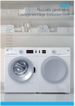
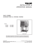
OWNER’S MANUAL STEAM-TECHTM ELECTRIC STEAM COOKER MODELS: ST-3E ST-6E INSTALLATION, OPERATION, MAINTENANCE, SERVICE AND PARTS MANUAL An Employee Owned Company 35 Garvey Street • Everett • MA 02149 Tel: (617) 387-4100 • Fax: (617) 387-4456 • Toll Free: (866) 698-3188 • Outside MA Fax: (800) 227-2659 E-mail: [email protected] • Web site: www.mfii.com FORM NO. S-2470 REV. A 08/06 Printed in U. S. A. TABLE OF CONTENTS INTRODUCTION DESCRIPTION .......................................................... 1 BASIC FUNCTIONING . ............................................ 1 SERVICE . ................................................................. 1 INSTALLATION ASSEMBLY ............................................................... 2 SETTING IN PLACE ................................................. 2 SERVICE CONNECTIONS ....................................... 2 WATER CONNECTIONS .......................................... 2 ELECTRICAL CONNECTIONS . ............................... 2 WATER CONNECTIONS........................................... 2 ELECTRICAL CHARACTERISTICS CHART ............ 2 INTERNAL DIMENSIONS & CAPACITY CHARTS ... 2 REVERSING THE DOORS....................................... 2 DIMENSIONS............................................................. 3 TYPICAL DOOR LAYOUT . ....................................... 3 SUPPLEMENTAL WIRING SHEET............................ 4 MECHANICAL WIRING DIAGRAM . ......................... 5 DIGITAL WIRING DIAGRAM . ................................... 6 INITIAL SYSTEMS INSPECTION GENERAL.................................................................. 7 WARM-UP ................................................................. 7 TIMER STEAM MODE .............................................. 7 CONSTANT STEAM MODE . .................................... 7 OPTIONAL STEAM & HOLD MODE . ....................... 7 OPTIONAL DIGITAL CONTROL TIMER ................... 7 SHUT-DOWN OPERATION CONTROLS & INDICATORS .................................... 7 OPERATING PROCEDURES ................................... 7 START-UP & PREHEATING ..................................... 7 COOKING-MECHANICAL CONTROLS . .................. 8 COOKING-USE OF THE DIGITAL TIMER ................ 7 CONTROLS & INDICATORS LOCATIONS . ............. 8 DAILY CLEANING ..................................................... 9 PROLONGED SHUT-DOWN & CLEANING ............. 9 GENERATOR CLEANING . ....................................... 9 MECHANICAL TIMER .............................................. 10 MECHANICAL TIMER WITH HOLD . ........................ 11 DIGITAL TIMER . ....................................................... 12 PRINCIPLES OF OPERATION GENERAL ................................................................. 13 FILL/COLD WATER INLET ....................................... 13 PREHEATING & STANDBY ...................................... 13 STEAM GENERATOR . ............................................. 13 HOLD FEATURE (OPTION) . .................................... 13 DRAINAGE . .............................................................. 13 COOKING COMPARTMENT DRAINAGE ................. 13 STEAM GENERATOR DRAINAGE . ......................... 13 TROUBLE-SHOOTING GENERAL ................................................................. 14 WATER LEVEL CONTROL BOARD ......................... 14 TESTING THE WATER FILL RELAY . ....................... 14 TESTING THE LOW WATER FILL RELAY................ 14 WATER LEVEL CONTROL BOARD IMAGE ............. 15 TROUBLE-SHOOTING GUIDE . ............................... 16 MAINTENANCE GENERAL ................................................................. 17 DAILY CLEANING ..................................................... 17 PREVENTIVE MAINTENANCE ................................ 17 CLEANING THE GENERATOR ................................ 17 CLEANING INSTRUCTIONS .................................... 18 CONTROL PANEL ELECTRICAL SERVICE ACCESS ................................................... 18 DOOR ADJUSTMENT . ............................................. 18 DOOR ALIGNMENT .................................................. 18 DOOR LATCH TENSION ADJUSTMENT ................. 19 DOOR HANDLE TENSION ADJUSTMENT .............. 19 DOOR GASKET REPLACEMENT ............................ 19 SOLENOID FILL VALVE STRAINER SCREEN CLEANING................................................. 19 ILLUSTRATED PARTS LIST TOP LEVEL ASSEMBLY ........................................... 20 GENERATOR ASSEMBLY ........................................ 22 LIST OF HEATING ELEMENTS . .............................. 22 DOOR ASSEMBLY . .................................................. 23 ELECTRICAL ASSEMBLY.......................................... 24 DIFFERENT CONFIGURATIONS OF ELECTRIC SUBASSEMBLY BY CONTROL BOARD................... 24 MECHANICAL PANEL WITH/WITHOUT COOK AND HOLD ASSEMBLY ............................................ 25 DIGITAL PANEL ASSEMBLY PLUMBING ASSEMBLY . .......................................... 26 INTRODUCTION DESCRIPTION: The Steam-Tech represents the latest in counter top steam technology, designed to apply the benefits of steam cooking to today’s health-conscious menus. Ideal for batch cooking, à-la-carte and rethermalization of individual entrées, the Steam- Tech puts the power of steam on your countertop. The Steam-Tech is a pressureless steam cooker consisting of: 3-pan or 6-pan cavity Electric pressureless generator (9, or 14kW inputs) Controls - mechanical or electronic Cleaning indicator Optional hold feature These features and functions will be discussed in greater detail in the initial systems inspection section on page 7. for the duration of time you have set. Once the timer reaches the end of its cycle (0 minutes) the buzzer will sound. The buzzer is silenced by returning the timer knob to the “off” position, which ceases the steaming function. The generator will continue to idle at 195°F. For units equipped with the optional digital timer, please refer to the optional digital control timer section on page 7 for basic explanation. For units equipped with the optional steam and hold feature, an additional mode selector switch is used to place the cooker into the hold mode. At the completion of the cooking cycle, place the timer knob to the “off” position and then place the hold switch to the “on” position. The hold feature is controlled by a separate thermostat with an additional temperature gauge mounted just above the control panel. The unit will now act as a holding cabinet until you call for steam again. During this time, the generator will continue to idle at 195°F. A “clean generator” light indicates when it’s time to delime. Generators can be easily cleaned from the outside of the cooking compartment, through a port on top. A “close-coupled” steam generator system gives quick start-ups and efficient steam transfer to the cooking compartment, without the use of fans or expensive blower motors. In tests for energy efficiency and cooking times performed in accordance with ASTM standards, the Steam Tech™ yielded impressive results over other similar counter top steamers. Your new cooker is equipped with a clean generator light which automatically illuminates when the steam generator has accumulated mineral build-up. When the clean light is “on” this indicates that the heating element has reached a point where it is not safe to operate the steamer without cleaning the generator and electric heater. To prevent heater burn-out, the steam generator must be cleaned (Refer to the trouble-shooting and maintenance sections of this manual). With an optional “hold” feature, your Steam Tech™ will keep cooked foods at 160°F until you are ready to serve, giving you more time between cooking and serving - it’s a Market Forge exclusive. Steam or hot water leaving the unit is drained out the rear of the cooking cavity. Your unit is equipped with a drain water cooling system which adds cold water to this discharge. The cold water cools the hot discharge below 140°F which is suitable for standard drain lines. (Note: Do not use PVC or CPVC for drain piping.) As your operation grows, so does your Steam Tech™. By stacking multiple Steam Tech™ models, you can accommodate up to 10 pans, creating a complete high-output steam cooking system. BASIC FUNCTIONING: To begin operation, the power switch is pressed into the on position, illuminating the power light. This opens the water feed solenoid valve to the steam generator. Once the appropriate water levels have been reached, the heating element is energized. When the water in the steam generator has reached 195°F, the green ready light, is illuminated, indicating that the unit is now ready to make steam and all controls are functional. SERVICE: Required service, both preventative and corrective, is explained in trouble-shooting and maintenance sections. Should repairs be required, a network of Authorized Agencies is available to assist with prompt service. A current Directory of Authorized Service Agencies may be obtained by contacting: Market Forge Industries, Inc. Everett, Massachusetts 02149-4403 Telephone: (617) 387-4100 • Toll Free: (866) 698-3188 Fax: (617) 387-4456 • Outside MA Fax: (800) 227-2659 [email protected] • www.mfii.com A steaming mode is selected, with the timer/selector switch. For continuous steam, set the selector timer knob to the “constant steam” position (the green area of the selector/timer switch). The cooker will continue to steam until the switch is moved to the “off” position. If you desire a timed steam cooking cycle, just set the timer knob to the cook time (up to 60 minutes). The Model and Serial Numbers must be referenced when corresponding with Market Forge. The data plate containing the serial number is located on the top front of the steamer (body panel). In the timed steam mode, the cooker will create steam 1 INSTALLATION ASSEMBLY: The assembled Steam-Tech™ Pressureless Steam Cooker is shipped in a carton on a skid. Steps required for assembly are as follows: 1. Remove the carton and the unit off the skid. 2. Install the feet into the threaded mounting locations on the bottom of the unit. 3. Mount the left and right pan support racks on the mounting brackets located inside each of the cooking compartments. 4. Mount the drip trough to the front of the unit. Electrical Characteristics Electrical connection power supply should utilize wire suitable for 90°C. SETTING IN PLACE: If possible, a location should be selected under an exhaust hood which will remove small amounts of vapor emitted from the cooker during normal operation. Next, level the unit after it is placed in its final location. This is accomplished by turning the bottom part of the adjustable feet. Using the cabinet top as a reference, obtain level adjustment left-to-right and front-to-back. ST-3E ST-6E (9 kW) (14 kW) VOLTS (AC) 1 pH 3 pH 1 pH 3 pH 208 (197-219) 41A 46A 41A 41A 64A 64A 37A 37A 240 (220-240) 34A 38A 20A 22A 53A 58A 31A 34A 480 (360-500) 19A -- 11A -- 29A -- 17A -- 220/380, 3 pH, 4 Wire --- 11A -- --- 18A -- 240/415, 3 pH, 4 Wire --- 13A -- --- 19A -- INTERNAL DIMENSIONS: SERVICE CONNECTIONS: Service connections that are made at the back of the cooker, include (2) cold water inlet, drain, and electrical. (Refer to the electrical characteristics table on this page) MODEL HEIGHT WIDTH DEPTH ST-3E 10.7” (271mm) 14” (235mm) 22.5” (571mm) ST-6E 17.2” (436mm) 14” (235mm) 22.5” (571mm) CAPACITY: EQUIPMENT FAILURE CAUSED BY INADEQUATE WATER QUALITY IS NOT COVERED UNDER WARRANTY. PAN SIZE CAUTION: Do not use PVC or CPVC piping for inlet water service connections. Please refer to Figure 1 on page 3 for locations of water and drain connections. NUMBER OF PANS ST-3E ST-6E 12” x 20” x 1” 6 8 12” x 20” x 2 1/2” 3 5 12” x 20” x 4” 2 4 REVERSING THE DOORS: The Steam-Tech Pressureless Steam Cooker has a reversible cooking compartment door for your convenience. This section contains instructions for reversing this door. ELECTRICAL CONNECTIONS: CAUTION: Use copper wire only for power supply connections. 1. Turn off power to the unit. 2. Open the cooking compartment door 3. Remove the two screws that attach the top hinge to the front of the unit. 4. Slide the door upwards, off the bottom hinge. 5. Remove the two screws that attach the bottom hinge to the front of the units. 6. Remove the right and left side panels by unscrewing the one screw on each panel and sliding the panel down. 7. Remove the door interlock assembly by unscrewing the two nuts that hold it in place (assembly is attached to the screws in the top right hinge mounting holes, see Fig. 1). Please refer to Figure 1 on page 3 for locations of electrical service connections. WATER CONNECTIONS: Cold water 1/2” female compression fitting water line will have maximum of 50 psi and minimum of 25 PSI of water pressure. Drain pipe full 1” female NPT to open floor drain with air break. Do not exceed 8’ in length and no more than 2 elbows. Before connecting water to this unit, water supply should be analyzed to make sure hardness is no greater than 2.0 grains per gallon and pH level is within the range of 7.0-8.5. Water which fails to meet these standards should be treated by installation of a water conditioner. Equipment failure caused by inadequate water quality is not covered under warranty. 2 INSTALLATION 20.4" 518mm 15.8" 400mm 13. 3" 76mm E - Electrical Connection CW - Cold Water 2" D - Drain Connection 51mm D CW E 1" 25mm 24" 610mm 5 Pan 23.2" 589mm 3 Pan 16.7" 424mm 14. 15. 16. 17. 4" 102mm 3" 76mm 2" 51mm 18. 1.5" 38mm 19. 30" 762mm D .5" 13mm 20. Fig. 1 Dimensions 8. Remove the four screws in the right side hinge mounting holes and install them in the left side hinge mounting holes (where the hinges were originally mounted). 9. Using the nuts removed in step #6, reinstall the door interlock assembly onto the two screws in the lower left hinge mounting holes (see Fig. 1) with by moving the assembly over the cooking cavity to the other side of the unit. Rotate the door interlock assembly 180° for installation, so that the switch is now facing up. 10. Reinstall the top hinge and screws into the right lower hinge mounting holes. Rotate the hinge 180° for installation, so that the pin which the door rides on is now facing up. The hinge must be rotated because it will now function as the bottom hinge. DO NOT COMPLETELY TIGHTEN THE HINGE for installation so that the pin which the door rides on now facing up. The hinge must be rotated because it will now function as the bottom hinge. DO NOT COMPLETELY TIGHTEN THE HINGE MOUNTING SCREWS YET. These will be used later for adjusting the door. 11. Remove the door latch assembly from the face of the unit. The two nuts mounting the door latch are located behind the face of the unit and must be accessed where the right side panel was removed. 12. Remove the two white hole plugs from the left door latch mounting holes, and insert them into the right door latch mounting holes (where the door latch assembly was originally mounted). Rotate the door latch assembly 180°, and install into the left door latch mounting holes. (NOTE: Each stud on the latch assembly should have a plastic washer, a spring, a plastic washer and a Nyloc type nut.) To adjust the tension of the door latch, tighten both nuts down until the springs are fully compressed, then back each nut off 1 1/2 turn. Rotate the door 180° for mounting. Slide the remaining hinge into the top door bearing. Slide the door and hinge assembly down onto the hinge which you have already mounted to the front of the unit. Use the two screws to mount the top hinge into the right upper hinge mounting holes. DO NOT COMPLETELY TIGHTEN THE HINGE MOUNTING SCREWS YET. Slowly push the cooking compartment door closed until it is latched. The cooking compartment door can now be raised, lowered, and/or rotated into position by bumping it with the palm of your hand or by using a small rubber mallet. First, check the alignment at the front of the door by making sure that the striker in the door is centered with the latch mechanism on the front of the unit. LEFT DOOR LATCH MOUNTING HOLES TOP LEFT HINGE MOUNTING HOLES INTERLOCK ASSEMBLY POSITION WHEN DOOR IS REVERSED LOWER LEFT HINGE MOUNTING HOLES TOP RIGHT HINGE MOUNTING HOLES DOOR LATCH ASSEMBLY (ORIGINAL POSITION) Fig. 2 Typical Door Layout 3 INTERLOCK ASSEMBLY ORIGINAL POSITION LOWER RIGHT HINGE MOUNTING HOLES INTRODUCTION 21. Square the door to the unit by raising or lowering the hinge side of the door, keeping the latch centered with the striker. 22. 22. Visually inspect the door. Be sure that the door is square to the unit, the striker is centered with the latch, and the gasket is in contact with the entire lip of the cooking compartment. 23. 23. Gently open the cooking compartment door, tak- ing care not to move it out of position. 24. Tighten all 4 door hinge bracket mounting screws. 25. Close and visually inspect the door again, as described in step 22. 26. Reinstall the left and right side panels, using the screws for each panel. Fig. 3 Supplemental Wire Sheet 4 INSTALLATION Fig. 4 Mechanical Wiring Diagram 5 INSTALLATION Fig. 5 Digital Wiring Diagram 6 INITIAL SYSTEMS INSPECTIONS GENERAL: This section contains information for you to test and familiarize yourself with the operation of the Steam-Tech. After the cooker is completely assembled, all packaging materials removed, and all service connections are made, all systems must be given a thorough check-out before being put into operation. Be sure that the cooking compartment is empty, and both pan support racks are in place. Confirm that all service connections are correct. Close the cooking compartment door, and turn the timer knob to the “off” position. test the “hold” feature, use the following procedure: Step 1: With a cold compartment, turn power switch to “on.” Step 2: Immediately put the mode selector to “hold.” Step 3: After 3 minutes open the door and touch the wall of the cavity to see if it is warm. Step 4: If the wall is warm, then test is complete. Return hold mode to “off.” OPTIONAL DIGITAL CONTROL TIMER: To begin, turn the power switch to “on.” The cooker automatically fills the generator and begins the preheat. At the end of the preheat function, a green “ready” light will be illuminated. WARM-UP: Push the power switch to the “on” position. You will hear water entering the unit through the solenoid valve, filling the generator. Once the water level in the generator has reached the appropriate level, the solenoid valve will close, and the heater will energize. After a short time (approximately 10 minutes, depending on heater power), the green “ready” light will come on, indicating that the unit is ready to make steam. For “constant steam” operation, place the mode selector switch to the “constant steam” position. You should hear steam enter the cavity and the cold water entering the drain. This action overrides the digital timer even if the timer was counting down prior to selection of the “constant steam” function. To check for proper operation of the digital timer, do the following: TIMER STEAM MODE: Set the selector/timer knob to 10 minutes and close the door. Your will hear steam flow entering the cavity, and cold water flow into the drain. When the timer reaches 0 minutes, the buzzer will sound. The buzzer is silenced by returning the selector/timer knob to the “off” position. The green ready light will stay illuminated. Step 1: Select “timed steam” mode Step 2: Press “clear” on display and it should read “00:00.” Step 3: Enter 2 minutes into timer. Step 4: Press “start” on digital timer pad Step 5: Listen for steam entering cavity with steaming completed at end of cycle. If your unit has the “Steam and Hold” option, follow the instructions in the optional steam and hold mode section on page 7. CONSTANT STEAM MODE: The constant steam mode overrides all other cooking modes. This mode is entered by turning the selector/ timer knob to the constant steam position on the dial (green area). With the knob set for constant steam and the door closed, you should hear steam enter the cavity and cold water flow into the drain. SHUT-DOWN: No special procedure is necessary for shutting the unit down. Simply press the power switch into the “off” position. CAUTION: When the unit is not in use, leave the cooking compartment door slightly ajar to prolong the life of the door gasket. OPTIONAL STEAM & HOLD MODE: If your cooker is equipped with the “Steam and Hold” option, you enter this mode by placing the mode switch to the “Hold” position (Refer to the optional hold feature section on page 7). This mode only works if the steaming cycle has been completed and door is left closed. To OPERATION CONTROLS & INDICATORS: The controls and indicators used to operate the SteamTech pressureless steam cooker are listed and described in the controls and indicators locations on page 8. functions, please refer to the principles of operation section of this manual. START-UP & PREHEATING: The Steam-Tech pressureless steam cooker requires no start-up procedure. Simply press the power switch into the “on” position. The steam generator will fill up with water. Once full, the heater will automatically preheat the water in the generator to 195°F. This will take approximately 10 minutes. When the generator is ready to create steam the green ready light will come on. OPERATING PROCEDURES: This section includes general instructions for daily operation of the Steam-Tech pressureless steam cooker. You should review the initial systems inspection section thoroughly if you are unfamiliar with the functions of the Steam-Tech. If you require more detailed technical information on the Steam-Tech’s various systems and their 7 OPERATION COOKING - MECHANICAL CONTROLS: NOTE: THE GREEN STEAMER READY LIGHT MUST BE ON BEFORE ANY CONTROLS BECOME OPERATIONAL. 1. Slide pans of food into the cooking compartment pan support racks. 2. Firmly close the cooking compartment door. 3. Begin steaming by either rotating the selection/timer knob to either the constant steam position or a desired cooking time. 4. At the end of the cook cycle (the buzzer will sound when the timer has timed out to zero, return the timer knob to the off position, which will turn off the buzzer. 5. If the unit is in constant steam mode, it will continue to provide steam to the cavity until the selector/timer is turned to the “off” position. Opening the door will interrupt the flow of steam to the cavity. 1. Close the door 2. Move mode selector switch to the “constant steam position”. 3. To exit “constant steam”, move mode selector switch to the “timed steam”. For timed steam cooking, do the following: 1. Place the mode switch to the “timed steam” position. 2. Press the “CLEAR” button on the timer. 3. Enter the desired time up to 99 minutes. 4. Press “START”. NOTE: The timer will not start counting down unless the door is closed. 5. When the timer counts down to “ZERO”, the beeper goes off until the “START STOP” button is pressed, steaming stops and the unit returns to a preheated stand-by mode. When you press stop, the existing program remains in the system. It is necessary to press clear, then re-program the time needed. 6. To shut-down the unit simply press the power switch to the “off” position. NOTE: When the cooking compartment isn’t in use be sure to leave the door slightly ajar to prolong the door gasket life. COOKING - USE OF THE DIGITAL TIMER: NOTE: THE GREEN READY LIGHT MUST BE ON BEFORE ANY CONTROLS BECOME OPERATIONAL. The cooker with the digital timer can be used in either a constant steam or timed steam mode For “constant steam” cooking, do the following: CONTROLS & INDICATORS LOCATIONS: Power Switch Located in the middle of the control panel. Pressing this button into the “on” position will supply power to the unit. Pressing this button into the “off” position will cut off power to the generator, and allow the system to drain. Ready Light Located above the power switch. It lights up green when the corresponding generator has warmed up to 195oF, indicating that it is ready to create steam. Mode Selector Switch (Digital controls only) Located in the center of the control panel, just above the ready light. Turn the switch to timed steam or constant steam. Timer Knob Located near the top of the control panel. Turn the timer knob to set the cook time. Temperature Gauge (Hold option only) Located at the bottom of the control panel, it is used to monitor the internal temperature of the cooking compartment during the hold mode. Constant Steam Position Located on the timer knob (selection/timer switch), the constant steam feature is entered by turning the knob clockwise to the green area (marked constant steam) Clean Generator Located on the right side of the control panel. This will light up red when the generaWarning Indicator & Switch tor needs to be de-limed. Refer to generator cleaning on page 9. Reset Button Located below the control panel. This will be used for the cleaning procedure. 8 OPERATION DAILY CLEANING: After each period of daily operation (more frequently as required to maintain cleanliness) the cooker should be thoroughly cleaned by completing the following steps: tor needs to be cleaned. Your steamer permits you to quickly clean the generator. The cleaning sequence is as follows: • The red “CLEAN” light illuminates when scale buildsup in the tank and on the heating element 1. Remove the baffle, and left and right side pan support racks by lifting them up off their mounting brackets. 2. Remove the drain screen by lifting it off its mounting studs. 3. Wash cooking compartment interior using detergent and water. Rinse and dry thoroughly. 4. Remove the drip/spill trough. 5. Wash all removed pieces with a detergent, using a brush, and rinse. These pieces can also be sent through a commercial automatic dish washing machine. Set these pieces aside for reassembly. 6. Replace the drip/spill trough. 7. Replace the drain screen inside the cavity. 8. Replace baffle, and pan supports into cooking cavity by hanging them on their mounting brackets. 9. Leave door slightly ajar. • When the unit is to be used the unit must be cleaned, as follows. 1. 2. 3. 4. Turn the power switch to the off position Turn off the water supply from its source Turn power switch on Red light is “on” and the generator will not fill with water. 5. Locate the reset switch on the control panel depress it, and the red light should turn off. 6. Remove the cleaning solution inlet cap located on the right hand side of the upper brow. 7. Using a kitchen funnel, pour Market Forge’s TOTAL CONCEPT de-liming solution (P/N 20-0318) into the generator (2 quarts). 8. Add 5 quarts of water to fill the generator to 3/4. The heater relay will click on. CAUTION: Read directions and information on TOTAL CONCEPT de-liming solution container before using. 9. Allow the unit to preheat until the green “READY” light comes on. 10. After the ready light is on, set the timer for about 20 minutes. 11. When the timer has counted to zero the system needs to be rinsed which is accomplished by: □ Turning the power OFF (the unit drains). □ Turn the water supply on at its source. □ Turning ON the power permitting water to enter the generator. □ Allowing the unit to reach preheat conditions (green light on). □ Setting timer for 10 minutes. □ Draining the rinse water after the buzzer sounds by turning OFF the power. PROLONGED SHUT-DOWN & CLEANING: This section includes instructions for prolonged shutdown of the Steam Tech™ pressureless steam cooker. 1. Press the power switch into the “off” position. The steam generator will automatically drain. 2. Clean the cooking compartment, as described in the daily cleaning section above. 3. The Steam Generator must be rinsed and drained. Refer to the generator cleaning below for complete instructions. CAUTION: • Disconnect the power supply to the steam generator before servicing. • Contact the Factory, the Factory Representative, or a • Factory Authorized Service Company to perform maintenance repairs. • Keep this manual for daily reference. After rinse water is drained, turn the power on, wait for the steam ready light, and you are ready to cook. If the clean light comes back on the cleaning procedure must be followed again. GENERATOR CLEANING: The Steam-Tech is designed with an advanced cleaning system which notifies the user that the steam genera- 9 OPERATION Fig. 6 Mechanical Timer (Control Panel) 10 OPERATION Fig. 7 Mechanical Timer with Hold (Control Panel) 11 OPERATION Fig. 8 Digital Timer (Control Panel) 12 PRINCIPLES OF OPERATION GENERAL: The Steam-Tech represents the latest in counter top steam technology, designed to apply the benefits of steam cooking to today’s health-conscious menus. A “closecoupled” steam generator system gives quick start-ups and efficient steam transfer to the cooking compartment, without the use of fans or expensive blower motors. In tests for energy efficiency and cooking times performed in accordance with ASTM standards, the Steam-Tech yielded impressive results over other similar counter top steamers. This section includes explanations of the steam generation, control, and drainage. generation of steam when it is called for. When steam is called for, a circuit is closed which activates a relay. This relay closes the 208v, 240v, or 480v circuit which supplies power to the heater. The generator now begins to create steam. Steam passes from the steam generator directly through the side of the cooking compartment. The fresh steam entering the cooking compartment forces the colder air to the bottom of the compartment and down the cooking compartment drain line. The cooking compartment drain line then has cooling water is sprayed into the drain flow. The cooling water is controlled by a thermostat located downstream of the cooling water nozzle. This configuration reduces the drain flow temperature to below 140°F. When the unit is steaming, the cooling water flow is on continuously. The cooling water comes “on” demand during other steamer functions such as generator blow-down (drain). FILL/COLD WATER INLET: When the power switch is pressed into the “on” position, a normally closed solenoid operated fill valve energizes and opens. The valve supplies cold water to the steam generator. At the same time, a normally open solenoid operated drain valve energizes and closes allowing the steam generator to fill with water (until the factory predetermined level is reached). HOLD FEATURE (OPTION): The Steam-Tech has a unique hold option which allows it operate as a holding cabinet at the end of a steaming cycle. The optional hold feature is activated by selecting the hold mode using the mode switch at the end of the steam cycle. While in the hold mode the generator will idle at 195°F, ready to create steam again. The water level in the steam generator is sensed by high and low water sensor probes which are mounted on the front of the generator. The probes are connected to the electronic water level control board which, controls the opening and closing of the generator fill valve. When the water level has reached the high water level sensor probe, the electronic board cuts power to the generator fill valve. As steam is created and used up, the water level in the steam generator will drop. When the water level falls below the level of the high water level sensor rod, the electronic board will close the circuit to the generator fill valve, allowing fresh water to enter the generator until the water has risen back up to the level of the high water level sensor. When the thermostatic switch senses that the temperature of the cooking compartment has dropped below 170°F, it activates the steam generator. This will raise the temperature inside the cooking compartment. When the thermostatic switch senses that the temperature of the cooking compartment has risen to 175°F, it cuts power to the generator. This system insures that the internal temperature of the cooking compartment will stay within a safe holding temperature range of above 150°F. The temperature of the cooking compartment can be monitored by observing the temperature gauge. The temperature gauge is located at the bottom of the the control panel. PREHEATING & STANDBY: When the water level in the generator has risen up to the low water level sensor probe, the electronic water level control board closes a circuit which activates a relay. This relay supplies power to the heater. The heater will stay on at full power until the water temperature is sensed by a thermostatic switch mounted inside the steam generator, below the water level. The steam generator will standby or idle at 195°F ready to make steam when it is called for. STEAM GENERATION: The Steam-Tech will not create steam until it is called for. Steam is called for by setting the timer/selector switch to either constant steam or timed steam. The cooking compartment door contains a magnet which activates a magnetic reed switch.. The red switch is located behind the front face of the unit, next to the cooking cavity opening. When the door is opened, the magnet and switch are separated. This opens the circuit to the heater, which will halt the creation of steam, but allow the heater to maintain 195°F water temperature in the steam generator. When the unit is on, the heater will maintain 195°F water temperature in the steam generator, to insure quick DRAINAGE: COOKING COMPARTMENT DRAINAGE: The bottom of the cooking compartment is angled slightly towards the rear of the unit. This assures that any condensate build-up or spills will be directed towards the drain hole which is located at the bottom center at the rear of the cooking compartment. Any liquid exiting the cooking compartment runs down the cooking compartment drain tube and into the drain line. STEAM GENERATOR DRAINAGE: Steam generator drainage is controlled by a normally open solenoid operated drain valve. When the power switch is pressed into the “on” position, power is supplied to the drain valve, which causes it to close allowing the generator to fill. When the power switch is pressed into the “off” position, power to the generator drain valve is cut, causing it to open. The steam generator will now automatically drain. 13 TROUBLE-SHOOTING GENERAL: The information in this section is intended to assist the operator, maintenance and the service personnel in locating the source of problems which may occur with the cooker. Before following any of the procedures given in this section, the operator/maintenance person should be thoroughly familiar with the operation section of this manual. WARNING: When you turn the power on, there are terminals that carry 120 volts. Protect the ends of these disconnected wires to prevent shorting to hot leads. 4. Turn power ON. Using the voltmeter, check that the power being supplied to terminals L1 and L2 is 120 volts, plus 10%, minus 15%. If the problem cannot be readily corrected without the use of tools, the operator/maintenance person should contact the nearest Market Forge service agency for assistance. WATER LEVEL CONTROL BOARD: The Dual Function Water Level Controller is two controls on one board. One controller maintains correct water level in the generator, the other a low water safety cutoff. The following troubleshooting procedure will only determine if the Water Level Control Board is working properly, it will not determine why the board has failed. WARNING: This procedure exposes you to a shock hazard and must be performed only by qualified service technician. Improperly connected or malfunctioning water level controller may cause damage to the steam generator due to low water, or create a scalding hazard to the operator due to a hot water overflow condition. TOOLS REQUIRED: A digital or analog volt meter capable of reading 120 volts A.C. and a jumper wire with alligator clips. Procedure: 1. Turn off all power to the unit. 2. Remove control panel or right side access panelRefer to Figure 6-1 for relay locations and terminal identification. 3. Remove the wires from the terminal connectors “G, H, and LLCO.” 14 TESTING THE WATER FILL RELAY: 1. When the power is turned on, the LED (light emitting diode) next to the water fill really should be ON. Using the voltmeter, touching the probes to terminals L2 and N.O. next to the water fill relay should show 120 volts. Touching the probes to L2 and N.C. should show no voltage. 2. Connect the jumper to terminals “G” and “H.” After a delay of 4-5 seconds, the relay should switch and the LED will go OFF. Using the voltmeter, touching the probes to terminals L2 and N.O. of the water fill relay should show no voltage. Touching the probes to L2 and N.C. should show 120 volts. 3. Disconnect the jumper. TESTING THE LOW WATER FILL RELAY: 1. With the power ON, the LED next to the Low Water Relay should be OFF. Using the voltmeter, touch probes to the L2 and N.O. terminals next to this relay, there should be no voltage. Touching the probes to terminals L2 and N.C. should show 120 volts. 2. Connect the jumper to terminals “G” and LLCO”. The LED next to the Low Water Relay should turn ON immediately. 3. Touch the voltmeter probes to terminal L2 and N.O. next to the low water relay, there should be 120 volts. Touch the probes to terminals L2 and N.C., there should be no voltage. 4. Remove the jumper and turn OFF the power. Reconnect the disconnected wires; wire to terminal “G”, wire to terminal “LLCO”, and wire to terminal “N.O.” of the water fill relay. TROUBLE-SHOOTING Fig. 9 Water Level Control Board 15 TROUBLE-SHOOTING TROUBLE PROBABLE CAUSE REMEDY POWER light does not come on when 1. the POWER switch is pressed into the 2. ON position 3. No 120v power to unit. 1. Be sure 120v power supply is on. Fuse blown. 2. Replace fuse. Faulty POWER switch. 3. Check/replace POWER switch (P/n 08-6549). Water enters the steam generator very 1. slowly. Dirty strainer screen in the water fill 1. solenoid valve. 2. Dirt or lime accumulation on seat of 3. water fill solenoid valve. 2. Steam generator will not fill. Generator will not create steam Clean valve seat. Check inlet press. (25-50 PSI). 3. Low water pressure. 1. 2. Faulty generator fill solenoid valve. 1. Faulty generator drain solenoid valve. Lime Build-up on Probe . If 120v is verified at the fill solenoid coil, (see Fig. 13) but the valve fails to open, replace the valve (P/n 086498). 2. If 120v is verified at the drain solenoid coil, (see Fig. 13) but the valve fails to close, replace valve (P/n 085021). 3. Clean or Replace Probe (P/n 086337). 1. 208/240/480 power supply is not 1. on. Check to be sure 208/240/480 electrical service is turned on. 2. Faulty 195°F generator thermostat. 2. 3. Lime Build-up on Probe. Check/replace thermostat (P/n 086449). 3. Clean or Replace Probe (P/n 086337). 1. 208/240/480 power supply is not 1. connected or not turned on. Check to be sure 208/240/480 power is connected and on. 2. Cooking compartment door is ajar. 2. 3. Cooking compartment door out of alignment. Check to be sure that the cooking compartment door is closed and latched. Faulty door magnet or magnetic 3. reed switch. 4. Lime buildup on probe. Check to be sure cooking compartment door is properly aligned. 3. READY light will not come on. Clean/replace strainer screen. 4. 5. 6. Faulty circuit breaker (P/n 08-6472 / 10-5944). 7. Faulty steam relay or contactor. 8. Faulty control panel TIMER. 9. Faulty MODE selector switch Check magnet (P/n 08-5027). and reed switch (P/n 08-6308). Replace if needed. 5. Clean or replace probe (P/n 086337). 6. Check circuit breaker at your 208/240/480 volt service connection. Reset if necessary (P/n 086472/10-5944). 7. Check/replace steam relay or contactor if necessary (P/n 08-6472/105944). 8. Check/replace control panel TIMER if necessary (Mechanical 08-6464, Digital 08-6429). 9. Check/replace MODE SELECT switch if necessary (P/n 08-6550). 10. Wiring short. 10. Check wiring, at terminals. Generator continues to create steam 1. when the cooking compartment door is opened. 2. Faulty magnet reed switch (contacts 1. failed closed). Check magnetic reed switch. Replace if necessary (P/n 08-6308). Wiring short. Check wiring, at terminals. 2. 16 TROUBLE-SHOOTING TROUBLE PROBABLE CAUSE Generator doesn’t drain when the POW- 1. ER switch is pressed into the OFF position. 2. 3. CLEAN GENERATOR light stays on 1. after it has been cleaned (delimed) and rinsed. 2. Unit fails to hold. REMEDY Clogged or kinked generator drain 1. line. Clogged generator drain hole. Check to be sure that the generator drain line is not kinked and is free of debris. Faulty generator solenoid drain 2. valve. 3. Check to be sure the generator drain hole is free of debris. Faulty or incorrectly set CLEAN 1. GENERATOR thermostat. Depress reset button on front panel. Faulty CLEAN latching relay. 2. Check/replace if necessary 08-6474). Rebuild or replace generator solenoid drain valve (P/n 08-5021). (P/n 3. Wiring short. 4. Faulty Reset Switch 3. Check wiring, at terminals. 4. Check/Replace if necessary (P/n 08-6553) 1. Faulty hold thermostat 1. Replace (P/n 08-7521) 2. Faulty hold switch 2. Replace (P/n 08-6550) 3. Faulty timer 3. Check/replace control panel TIMER if necessary. (Mechanical 08-6464, Digital 08-6429) MAINTENANCE GENERAL: This section contains both preventive and corrective maintenance information. Preventive maintenance may be performed by maintenance personnel at the establishment in which the cooker is installed. It is recommended that user personnel never attempt to make repairs or replacements to the equipment. Assistance in service methods or a current directory of authorized agencies may be obtained from Market Forge Industries. 7. Replace the drain screen inside the cavity. 8. Replace baffle, and pan supports into cooking cavity by hanging them on their mounting brackets. 9. Leave door slightly ajar. PREVENTIVE MAINTENANCE: A good preventive maintenance program begins with the daily cleaning procedure described above. Additional preventive maintenance operations are presented in this section. In establishments which employ full-time maintenance personnel, the tasks described can be assigned to them. For other installations, tasks requiring mechanical or electrical experience must be performed by an authorized service agency. DAILY CLEANING: After each period of daily operation (more frequently as required to maintain cleanliness) the cooker should be thoroughly cleaned by completing the following steps: 1. Remove the baffle, and left and right side pan support racks by lifting them up off their mounting brackets. 2. Remove the drain screen by lifting it off its mounting studs. 3. Wash cooking compartment interior using detergent and water. Rinse and dry thoroughly. 4. Remove the drip/spill trough. 5. Wash all removed pieces with a mild detergent, using a brush, and rinse. These pieces can also be sent through a commercial automatic dish washing machine. Set these pieces aside for reassembly. 6. Replace the drip/spill trough. CAUTION: Under no circumstances should hardware (or parts) be replaced with a different size or type other than as specified in the parts list. The hardware used in the cooker has been selected or designed specifically for its application and the use of other hardware may damage the equipment, present a safety hazard and will void any warranty. The following sections set forth minimum preventive maintenance procedures which must be completed periodically to assure continued trouble-free operation. CLEANING THE GENERATOR: The Steam Tech Pressureless Steam Cooker has an au17 MAINTENANCE tomatic indicator light which tells you when the steam generator needs to be cleaned. front of the unit. CAUTION: Be sure to disconnect the power supply from the unit before servicing any electrical components. CLEANING INSTRUCTIONS: The cleaning sequence is as follows: • The red “CLEAN” light illuminates when scale buildsup in the tank and on the heating element Procedure: 1. Remove the 6 screws that fasten the control panel assembly onto the front of the unit. 2. Gently move the control panel assembly out away from the unit. • When the unit is to be used the unit must be cleaned, as follows. 1. 2. 3. 4. Turn the power switch to the off position Turn off the water supply from its source Turn power switch on Red light is “on” and the generator will not fill with water. 5. Locate the reset switch on the control panel depress it, and the red light should turn off. 6. Using a kitchen funnel, pour Market Forge’s TOTAL CONCEPT de-liming solution (P/n 20-0318) into the generator (2 quarts). 7. Add 5 quarts of water to fill the generator to 3/4. The heater relay will click on. CAUTION: Read directions and information on TOTAL CONCEPT de-liming solution container before using. NOTE: A ground strap acting as a restrain prevents the control panel from putting unnecessary strain on wires and connections. DOOR ADJUSTMENT: The cooking compartment door alignment, door handle tension and latch tension are pre-adjusted at the factory during assembly. During normal usage, these should not need any attention. Note that when the cooking compartment doors are reversed, as described in the service connections section on page 2 of this manual, the doors will need to be aligned and the door latch tension will need to be adjusted (the door handle will not need adjustment when the door is reversed). 8. Allow the unit to preheat until the green “READY” light comes on. 9. After the ready light is on, set the timer for about 20 minutes. 10. When the timer has counted to zero the buzzer sounds and the system needs to be rinsed which is accomplished by: □ Turning the power OFF (the unit drains). □ Turn the water supply on at its source. □ Turning ON the power permitting water to enter the generator. □ Allowing the unit to reach preheat conditions (green light on). □ Setting timer for 10 minutes. □ Draining the rinse water after the buzzer sounds by turning OFF the power. After rinse water is drained, turn the power on, wait for the steam ready light, and you are ready to cook. If the clean light comes back on the cleaning procedure must be followed again. DOOR ALIGNMENT: The cooking compartment doors are pre-aligned at the factory during assembly, and should not need adjusting unless they are reversed. Should the doors need realignment, the procedure is as follows: Procedure: 1. Open the cooking compartment door. 2. Loosen all screws (2 per hinge) which mount the upper and lower hinge brackets to the face of the unit using a flat head screwdriver. DO NOT REMOVE THE SCREWS. 3. Begin to retighten all 4 screws so that they are snug against the face of the unit. DO NOT COMPLETELY TIGHTEN THE SCREWS! 4. Slowly push the cooking compartment door closed until it is latched. 5. The cooking compartment door can now be raised, lowered, and/or rotated into position by bumping it with the palm of your hand or by using a small rubber mallet. 6. First, check the alignment at the front of the door by making sure that the striker in the door is centered with the latch mechanism on the front of the unit. CONTROL PANEL ELECTRICAL SERVICE ACCESS: The control panel assembly is mounted on the front of the unit. It houses all of the controls and indicators which are used to operate the Steam-Tech. In order to service any of the control panel electrical components, the control panel assembly must be removed from the 7. Square the door to the unit by raising or lowering the hinge side of the door, keeping the latch centered with the striker. 8. Visually inspect the door. Be sure that the door is 18 MAINTENANCE square to the unit, the striker is centered with the latch, and the gasket is in contact with the entire lip of the cooking compartment. gasket leak, readjust the door gasket to the unit or replace it. Procedure: Replace Gasket: 1. Open the cooking compartment door. 2. Remove the (3) screws from the top of the door, and the (3) screws from the bottom of the door. 3. Remove the inner door, gasket plate and gasket. 4. Remove the (6) nuts on the back of the inner door. 5. Remove the door gasket mounting plate and the door gasket. 6. Install the new door gasket (Refer to the door assembly parts list on page 23 for part number) to the mounting plate. 7. Reassemble the mounting plate with gasket to the inner door using the (6) nuts. NOTE: Remember that the lip on the door gasket mounting plate must fit into the channel on the inside edge of the gasket to insure a proper seal. 9. Gently open the cooking compartment door, taking care not to move it out of position. 10. Tighten all 4 door hinge bracket mounting screws using a flat head screwdriver. 11. Close and visually inspect the door again, as described in step 8. DOOR LATCH TENSION ADJUSTMENT: CAUTION: Shut off main electrical power to unit. Procedure: 1. Open the cooking compartment door. 2. Remove the control panel. By removing the six mounting screws, and disconnecting the wire plug and restraining wire. 3. Tighten both nuts down until the springs are fully compressed. 4. Back each nut off 1 1/2 turn. 5. Remount the control panel. Reconnecting wire plug and restraining wire. 8. Reassemble the inner door, mounting plate, and gasket with the outer door using the (3) screws on the top and bottom of the door. Procedure: To Adjust Gasket To Unit: To prevent steam leaks around the door adjust the gasket tension to cavity. Adjust the gasket by loosing (6) screws on top & bottom of door, move inner door plate in or out, left side or right side and tighten (6) screws. DOOR HANDLE TENSION ADJUSTMENT: Procedure: 1. Open the cooking compartment door. 2. Remove the (6) screws and washers, from the top edge and from the bottom edge of the door. 3. Remove the inner door gasket mounting plate assembly, from the outer door. Do not disassemble these three components, remove them as an assembly. 4. Tighten both nuts down until the springs are fully compressed. 5. Back each nut off 1/2 turns. 6. Remount the inner door gasket, mounting plate assembly by assembling the (6) screws and washers. SOLENOID FILL VALVE STRAINER SCREEN CLEANING: The solenoid operated fill valves contain a built-in strainer screen inside the valve body. This screen must be removed and cleaned periodically (depending on usage and water quality) to remove any debris or lime build-up which will accumulate during normal operation. Procedure: 1. Remove the back panel of the unit. 2. Unscrew screen plug from valve and remove screen. 3. Clean screen and reassemble screen and screen plug into valve body. 4. Replace the back panel. DOOR GASKET REPLACEMENT: The cooking compartment door gaskets are made of a silicone type rubber material, which is very durable, but is subject to wear during normal operation. Should the 19 ILLUSTRATED PARTS LIST FIGURE 7.1 TOP LEVEL ASSEMBLY Fig. 10 Top Level Assembly 20 ITEM ST-3E PART NO. ST-6E PART NO. 1 REF. --- BOILER ASSY. 1 2 REF. --- ELECTRICAL ASSY. 1 3 08-6498 --- SOLENOID VALVE 1 4 10-1055 --- ELBOW, STREET, 3/8” NPT 2 5 08-4863 --- HOSE BARB, 3/8” NPT X 1/4 ID HOSE 2 6 91-7652 91-7653 PANEL, SIDE 2 7 REF --- PLUMBING ASSY. 1 8 91-6838 91-6839 GASKET, INLET 1 9 91-7690 --- BRACKER, REED SWITCH 1 10 08-6308 --- REED SWITCH 1 DESCRIPTION QTY. 11 08-6553 --- RESET THERMOSTAT 1 12 08-7520 --- LEG, ADJUSTABLE 4 13 REF. REF. CONTROL PANEL 1 14 91-7697 91-7698 BAFFLE 1 15 91-6493 91-6486 DOOR ASSY. 1 16 91-7497 --- DRIP TROUGH 1 17 91-5700 91-7699 RACK 2 18 91-7684 --- STRAINER 1 19 91-7414 --- SEALING PLATE 1 20 91-7415 --- GASKET, LINER FRONT 1 21 91-7416 --- PLATE, RETAINING 1 22 09-6428 --- THERMOSTAT, COOK & HOLD UNITS ONLY 1 23 91-7660 --- PANEL, TOP 1 24 08-5894 --- CASTING, NAME PLATE 1 25 08-7807 --- TINERMAN CLIP 2 26 91-7765 --- CLEAN PLUG 1 27 08-7511 --- O RING, CLEAN PLUG 1 28 91-7594 --- CLEAN ME PORT 1 29 SEE NOTE --- TRANSFORMER 1 30 08-6555 --- TERMINAL BLOCK 1 31 91-6779 --- JUNCTION BOX 1 32 09-6575 --- BUSHING, WIRING 1 33 91-6491 --- GROMMET 1 34 08-4981 --- BULKHEAD, 1/2” NPT X 3/8” NPT 2 35 08-7548 --- ELBOW, 1” NPT 1 36 08-1207 --- HOSE BARB, 1” NPT X 1 ID HOSE 1 37 91-6840 --- DRAIN BOX ASSY 1 38 98-1477 --- HOSE BARB, 3/8” NPT X 3/8 ID HOSE 1 39 08-7513 --- THERMOSTAT, 135 F 1 40 91-7674 91-7705 REAR POST 2 41 91-7654 91-7655 PANEL, REAR 1 42 10-3343 --- NUT, 1/2” NPT 1 43 08-4892 --- HOSE BARB, 1/2” NPT X 3/8 ID HOSE 1 44 08-4866 --- SPRAY NOZZLE 1 45 08-4978 --- HOSE BARB, 3/8” NPT X 1/4 ID HOSE, FEMALE 1 46 91-7668 --- PANEL, ACCESS 1 o NOTE: 480V UNITS HAVE (2) ALL OTHERS HAVE (1). ILLUSTRATED PARTS LIST LIST OF HEATING ELEMENTS PART NO. MODEL NO. kW RATING VOLTAGE 08-6485 ST-3E 9 208 08-6486 ST-3E 9 240 08-6487 ST-3E 9 480 08-6491 ST-6E 14 208 08-6492 ST-6E 14 240 08-6493 ST-6E 14 480 ITEM NO. PART NO. 1 91-7707 BOILER BODY WELD ASSY. 1 2 91-6444 BOILER FRONT GASKET 1 3 91-7711 BOILER FRONT PLATE 1 4 08-6337 WATER LEVEL PROBE 2 5 91-8660 ELEMENT GASKET 1 6 08-6449 THERMOSTAT, 195OF 1 7 --- SEE LIST OF HEATING ELEMENTS TABLE ABOVE 1 DESCRIPTION QTY. NOTE: OLDER UNITS ONLY REPLACED WITH KIT # 91-6791. ELIMINATED ON LATEST MODELS. Fig. 11 Top Generator Assembly 22 ILLUSTRATED PARTS LIST Fig. 12 Door Assembly ITEM NO. ST-3E PART NO. ST-6E PART NO. DESCRIPTION QTY. 1 91-5729 91-7692 OUTER DOOR 1 2 91-5766 91-7694 INNER DOOR 1 3 91-5731 91-7696 GASKET RETAINING PLATE 1 4 91-5286 91-7783 DOOR GASKET 1 5 91-5745 --- DOOR HANDLE 1 6 09-1608 --- STRIKER 1 7 08-5027 --- MAGNET 1 8 91-5901 --- MAGNET BRACKET 1 9 08-4600 --- COMPRESSION SPRING 2 23 ILLUSTRATED PARTS LIST Fig. 13 Electrical Subassembly ITEM NO. PART NO. 1 91-7718 ELECTRIC PLATE 1 08-6328 LIQUID LEVEL BOARD 1 2 3 DESCRIPTION QTY. SEE NOTE 2 CONTACTOR 1 4 08-6479 FUSE BLOCK 2 5 08-6468 FUSE 5A 2 8 08-6472 RELAY 2 7 08-6475 RELAY BASE 2 8 09-6575 BUSHING, PLASTIC 9 08-6450 120 TO 240V TRANSFORMER SEE NOTE 1 10 08-6472 RELAY SEE NOTE 1 11 08-6475 RELAY BASE SEE NOTE 1 1 NOTES: 1. One of each of these components are used on digital only. Mechanical timer units use none. 2. Single phase 208 and 240 volt six pan units use part number 09-6483. All others use part number 10-5944. DIFFERENT CONFIGURATIONS OF ELECTRICAL SUBASSEMBLY BY CONTROL OPTION CONTROL OPTION NOTES MECHANICAL TIMER OMIT R3 RELAY AND BASEM OMIT T1 MECHANICAL TIMER WITH HOLD OMIT R3 RELAY AND BASEM OMIT T2 DIGITAL TIMER --- 24 ILLUSTRATED PARTS LIST Fig. 14 Mechanical Panel with Cook & Hold Assembly ITEM NO. ST-3E PART NO. ST-6E PART NO. Fig. 15 Digital Panel Assembly DESCRIPTION QTY. MECHANICAL PANEL WITH COOK AND HOLD ASSEMBLY 1 91-7703 91-7704/24 CONTROL PANEL 1 2 91-6437 --- GRAPHICS 1 3 08-6464 --- TIMER 1 4 08-7516 --- TIMER KNOB 1 5 08-6467 --- RED LIGHT 1 6 08-6466 --- GREEN LIGHT 1 7 08-6549 --- POWER SWITCH 1 8 10-7395 --- BUZZER 1 9 08-6552 --- TERMINAL SWITCH 1 10 08-6550 --- MODE SWITCH (WITH HOLD ONLY) 1 11 08-7521 --- THERMOMETER (WITH HOLD ONLY) 1 DIGITAL PANEL ASSEMBLY 1 91-6835 91-6836 CONTROL PANEL 1 2 91-7687 --- GRAPHICS 1 3 08-6429 --- DIGITAL TIMER 1 4 08-6552 --- TERMINAL STRIP 1 5 08-6551 --- MODE SWITCH 1 6 08-6467 --- RED LIGHT 1 7 08-6446 --- GREEN LIGHT 1 25 ILLUSTRATED PARTS LIST Fig. 16 Plumbing Assembly ITEM NO. PART NO. 1 SEE NOTE 2 DESCRIPTION QTY. ELBOW, STREET, HOSE BEAD 1 08-5021 DRAIN VALVE 1 3 10-3862 REDUCER 1 4 10-1014 NIPPLE, CLOSED 2 5 10-1055 STREET ELBOW 3 8 10-1054 TEE 1 7 08-6498 SOLENOID 1 8 08-4863 HOSE BARB 1 9 10-3684 COMPRESSION FITTING 1 NOTE: 3 pan units use part number 08-5072 and 6 pan units use part number 10-0937. 26