1
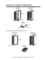
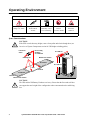
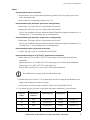
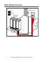
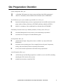
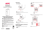
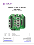
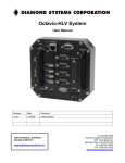
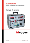
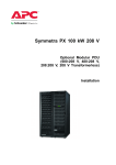
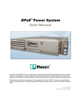
Symmetra PX
10-80 kW
208 V
Site Preparation Guide
Symmetra® PX
10-80 kW 208V
Site Preparation Guide
Sym
metra®
Quick
-Start
User
PX
Guide
Contents
IMPORTANT SAFETY INSTRUCTIONS . . . . . . . . . . . . . . . . . . . . . 1
SAVE THESE INSTRUCTIONS . . . . . . . . . . . . . . . . . . . . . . . . . . . 1
Symbols used in this guide . . . . . . . . . . . . . . . . . . . . . . . . . . . . 1
Overview of System Components . . . . . . . . . . . . . . . . . . . . . . . 2
Option: Symmetra PX 10-80 kW Battery Enclosure . . . . . . . . . . 2
Operating Environment . . . . . . . . . . . . . . . . . . . . . . . . . . . . . . 3
Space Considerations . . . . . . . . . . . . . . . . . . . . . . . . . . . . . . . . 3
System Electrical Information . . . . . . . . . . . . . . . . . . . . . . . . . . 4
Notes . . . . . . . . . . . . . . . . . . . . . . . . . . . . . . . . . . . . . . . . . . . . 5
EPO switch wiring (required) . . . . . . . . . . . . . . . . . . . . . . . . . . 6
For installations in US . . . . . . . . . . . . . . . . . . . . . . . . . . . . . . . . 6
For installations in Canada . . . . . . . . . . . . . . . . . . . . . . . . . . . . 6
Option: 10-80 kW Battery Enclosure . . . . . . . . . . . . . . . . . . . . . 6
Basic Wiring Overview . . . . . . . . . . . . . . . . . . . . . . . . . . . . . . . 7
Site Preparation Checklist . . . . . . . . . . . . . . . . . . . . . . . . . . . . . 8
Symmetra® PX 10-80 kW 208 V Site Preparation Guide - 990-1425A
i
IMPORTANT SAFETY INSTRUCTIONS
SAVE THESE INSTRUCTIONS
This guide contains information on how to prepare the site for the installation of the UPS and
optional equipment.
Symbols used in this guide
CAUTION!
Read this important information to avoid equipment damage.
Indicates that more information is available on the same subject in a different manual.
See also
1
Symmetra® PX 10-80 kW 208 V Site Preparation Guide - 990-1425A
Overview of System Components
UPS (Fully Loaded)
1166 lbs/529 kg
UPS (Empty)
650 lbs/295 kg
INTELLIGEN
CE MODULE
INTELLIGEN
CE MODULE
82 in/2080 mm
?
?
XR Communicati
36 in/915 mm
DOC
UME
NT STO
RAG
E
Sym
Ba 10
sic - 40me
Op kWtra
era , ® PX
tion200
GuV
ide
Sym
Ba 10
sic - 40me
Op kWtra
era , ® PX
tion200
GuV
ide
ons
DOC
UME
NT STO
RAG
E
24 in/610 mm
Power Module
60 lbs/26 kg
5.2 in/132 mm
19 in/483 mm
27.5 in/700 mm
Option: Symmetra PX 10-80 kW Battery Enclosure
Battery Enclosure
Empty: 455 lbs/206 kg
Battery Enclosure
Full: 2120 lbs/962 kg
BATTERY UNIT
82 in/2070 mm
24 in/600 mm
36 in/915 mm
Battery Module
(4 battery units)
4 x 50 lbs/4 x 23 kg
Symmetra® PX 10-80 kW 208 V Site Preparation Guide - 990-1425A
2
Operating Environment
Install the UPS in an Indoor, Controlled Environment
Temperature
Range: 32°-104°F
KeepVentilated
Front-to-Rear
Airflow
Relative
Humidity: <95%
Non-condensing
No Conductive
Dust or
Corrosive Fumes
Max.
Elevation:
10,000 ft.
Full Load Heat Loss at Nominal Mains: 23,743 BTU/hr (6,957 Watts)
Space Considerations
CAUTION!
If the UPS exceeds doorway height, remove from pallet and wheel through door (see
Overview of System Components section for UPS height excluding pallet).
Floor-to-ceiling
ventilation:
> 91 in/2300 mm
Front-to-rear
airflow
Stabilizing feet
47 in/1200 mm
Minimum rear clearance
36 in/915 mm
91 in/ 2300 mm
UPS
36 in/915 mm
36 in/915 mm
24 in/610 mm
Minimum front clearance
CAUTION!
The UPS and the XR Battery Enclosure are heavy. Ensure that the floor and sub-floor
can support the total weight of the configuration when concentrated on the stabilizing
feet.
3
Symmetra® PX 10-80 kW 208 V Site Preparation Guide - 990-1425A
System Electrical Information
CAUTION!
All electrical power and power control wiring must be installed by a qualified
electrician, and must comply with local and national regulations for maximum power
rating.
All current values are based on 80 kW maximum configuration of the UPS.
Note
Input
Input voltage
3-phase 208V (166-240V)
Input current (nominal, per phase)
244 A
Maximum input current (continuous, at minimum mains voltage)
321 A
Input current protection for mains source or single mains supply
(external to UPS, not supplied)
350 A *note 3
Input current protection for bypass source in dual mains configuration
(external to UPS, not supplied)
300 A *note 4
Input frequency (progammable)
50/60 Hz
Output
Output voltage (on line) 380 V
3-phase 208V
Output current (nominal)
222 A
Maximum output current (in bypass at 125% overload)
277 A
Neutral output current (with 100% switch mode load)
384 A *note 8
Output current protection (external to UPS, not supplied)
300 A *note 6
Output frequency (progammable)
50/60 Hz, Synchronized to bypass
input (if present)
Overcurrent device and disconnect switch for external safety
DC bus voltage (nominal)
+ 192 V
DC voltage rating of the battery supply
250 V
Maximum available battery supply fault current
10 KA
Symmetra® PX 10-80 kW 208 V Site Preparation Guide - 990-1425A
4
System Electrical Information
Notes
Recommended source connection.
1. Input electricity to be provided from a dedicated, grounded 4-wire Wye utility power source
with a grounded neutral.
2. Ensure clockwise voltage phase rotation (L1,L2,L3).
Recommended input protection (dual mains configuration).
3. Mains input: 350 Amp 3-Pole AC circuit breaker with 30 kAIC.
4. Bypass input: 300 Amp 3-pole AC circuit breaker with 30 kAIC.
Note: If your installation does not include an Isolation Transformer (optional equipment), use a
300 Amp Class “J” current limiting fuse on each input phase.
Recommended input protection (single mains configuration).
5. Mains input: 350 Amp 3-Pole AC circuit breaker with 30 kAIC.
Note: If your installation does not include an Isolation Transformer (optional equipment), use a
350 Amp Class “J” current limiting fuse on each input phase.
Recommended output (single and dual mains).
6. Output: 300 Amp 3-pole AC circuit breaker with 30 kAIC.
Recommended wiring for a 86oF/30oC temperature environment.
7. Mains input wires: 2×4/0 AWG 167oF/75oC rated copper wire (for single and dual mains
installation).
Bypass input wires: 2×3/0 AWG 167oF/75oC rated copper wire (for dual mains installation).
Output wires: 2×3/0 AWG 167oF/75oC rated copper wire.
Refer to NEC Articles 310-15, 310-16 and 315 for further information.
The installation must comply with local and national codes.
Note
8. Neutral output wires: rate for 173% of output phase current if feeding all Switch Mode Power
Supply loads without power factor correction.
9. Ground wires: sized in accordance with NEC Article 250-122 and Table 250-122.
10. Use Molex lug type (see table) or equivalent and crimp to manufacturer’s specifications.
Die
Cable Size
(AWG)
Terminal Bolt
Diameter
Cable Lug Type
CrimpingTool
1/0
M10
LCA1/0-38-X
CT-2001
CD-2001-1/0
2/0
M10
LCA2/0-38-X
CT-2001
CD-2001-2/0
3/0
M10
LCA3/0-38-X
CT-2001
CD-2001-3/0
4/0
M10
LCA4/0-38-X
CT-2001
CD-2001-4/0
Symmetra® PX 10-80 kW 208 V Site Preparation Guide - 990-1425A
5
System Electrical Information
This UPS system has no built-in disconnection devices for AC output and DC input. An AC output
over-current protection and AC output disconnect must be provided by the customer. For customersupplied external batteries, over-current protection and a disconnecting device for the battery circuits
must also be provided by the customer.
EPO switch wiring (required)
The UPS is to be connected to either a dry contact or a 24Vdc Emergency Power Off (EPO) switch.
The EPO circuit is considered Class 2 and SELV (Safety Extra Low Voltage). A SELV circuit is
isolated from primary circuitry through an isolating transformer and designed so that under normal
conditions, the voltage is limited to 42.4Vac peak or 60Vdc. SELV and Class 2 circuits must be
isolated from all primary circuitry. Do not connect any circuit to the EPO terminal block unless it can
be confirmed that the circuit is SELV or Class 2.
Use one of following cables to connect the UPS to the EPO switch:
For installations in US
– CL2Class 2 cable for general purpose use.
– CL2PPlenum cable for use in a vertical shaft or from floor to floor.
– CL2R Racer cable for use in dwellings and raceways.
– CL2XLimited use cable for dwellings and raceways.
For installations in Canada
– CL2RCertified, type ELC (Extra-Low-Voltage Control Cable).
– CL2XCertified, type ELC (Extra-Low-Voltage Control Cable).
Option: 10-80 kW Battery Enclosure
Option: 10-80 kW Battery Enclosure
Battery voltage (nominal)
+/- 192 V
Battery current (at full load)
223 A at +192 V
Max. current (at end of discharge)
266 A at +160 V
If battery enclosure is customer-supplied, refer to product-specific data.
6
Symmetra® PX 10-80 kW 208 V Site Preparation Guide - 990-1425A
Basic Wiring Overview
MBP (optional equipment)
AC Power
DC Power
Interface wiring
Battery Enclosure
(Optional, 4 Max.)
UPS
Output
Power
Input
Powerr
7
Symmetra® PX 10-80 kW 208 V Site Preparation Guide - 990-1425A
Site Preparation Checklist
System Components. Have you –
5
5
verified that UPS output power meets current and future load (kW) requirements?
added N+1 redundancy with an additional Power Module (Part # SYPM10KF).
The UPS houses up to 9 power modules (up to 80 kW, N+1). Have you 5
determined minimum battery run time requirement based on load (kW) and selected the
proper number of Battery Enclosures (SYCF8BF) and Battery Modules (SYBT4)?
5
added N+1 redundancy with an additional Power Module (Part # SYPM10KF).
Each Battery Enclosure houses up to 8 Battery Modules (32 battery units). Have you –
5
considered Management Card accessories to meet monitoring requirements?
5
considered Service Program or Extended Warranty plan?
Site Preparation. Have you –
5
verified that rated input voltage and current are available? (see System Electrical
Information).
5
considered correct operating space, floor strength (Section on System Components),
cooling, and environment (Section on Operating Environment).
5
reviewed all electrical requirements to determine wiring requirements?
Arrival Preparation. Have you –
5
verified that space and handling equipment are available to receive the UPS? (including
unloading the UPS from the delivery truck).
5
scheduled an electrician to install the UPS?
Symmetra® PX 10-80 kW 208 V Site Preparation Guide - 990-1425A
8
APC Worldwide Customer Support
Customer support for this or any other APC product is available at no charge in any of the following ways:
• Visit the APC Web site to access documents in the APC Knowledge Base and to submit customer
support requests.
– www.apc.com (Corporate Headquarters)
Connect to localized APC Web sites for specific countries, each of which provides customer
support information.
– www.apc.com/support/
Global support searching APC Knowledge Base and using e-support.
• Contact an APC Customer Support center by telephone or e-mail.
– Regional centers:
Direct InfraStruXure Customer Support
Line
(1)(877)537-0607 (toll free)
APC headquarters U.S., Canada
(1)(800)800-4272 (toll free)
Latin America
(1)(401)789-5735 (USA)
Europe, Middle East, Africa
(353)(91)702000 (Ireland)
Japan
(0) 35434-2021
Australia, New Zealand, South Pacific
area
(61) (2) 9955 9366 (Australia)
– Local, country-specific centers: go to www.apc.com/support/contact for contact information.
Contact the APC representative or other distributor from whom you purchased your APC product for
information on how to obtain local customer support.
Entire contents copyright © 2004 American Power Conversion. All rights reserved.
Reproduction in whole or in part without permission is prohibited. APC, the APC logo, and
Symmetra are trademarks of American Power Conversion Corporation and may be registered
in some jurisdictions. All other trademarks, product names, and corporate names are the
property of their respective owners and are used for informational purposes only.
990-1425A
*990-1425A*
03/2004