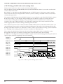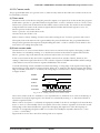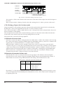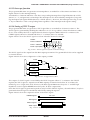
1
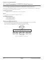
MF1195-03
CMOS 4-BIT SINGLE CHIP MICROCOMPUTER
S1C6P466
Technical Manual
S1C6P466 Technical Hardware
NOTICE
No part of this material may be reproduced or duplicated in any form or by any means without the written permission of Seiko
Epson. Seiko Epson reserves the right to make changes to this material without notice. Seiko Epson does not assume any
liability of any kind arising out of any inaccuracies contained in this material or due to its application or use in any product or
circuit and, further, there is no representation that this material is applicable to products requiring high level reliability, such
as medical products. Moreover, no license to any intellectual property rights is granted by implication or otherwise, and there
is no representation or warranty that anything made in accordance with this material will be free from any patent or copyright
infringement of a third party. This material or portions thereof may contain technology or the subject relating to strategic
products under the control of the Foreign Exchange and Foreign Trade Law of Japan and may require an export license from
the Ministry of International Trade and Industry or other approval from another government agency.
© SEIKO EPSON CORPORATION 2001, All rights reserved.
Revisions and Additions for this manual
Chapter
Appendix A
Appendix B
S1C6P466 Technical Manual
Section
A.2
Page
136
155
Item
Contents
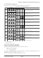
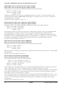
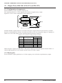
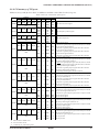
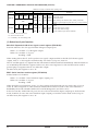
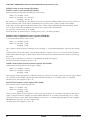
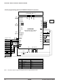
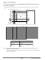
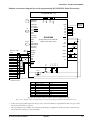
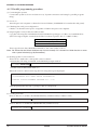
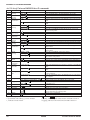
Fig. A.2.4.1 Connection diagram for serial The diagram was revised.
programming (S1C88/S1C63 Serial
Connector)
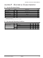
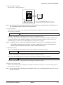
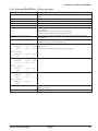
Table A.2.4.1 Signal specifications
The table was revised.
Appendix B
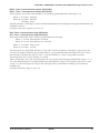
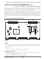
Appendix B was added.
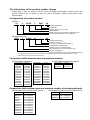
The information of the product number change
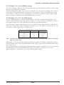
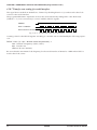
Starting April 1, 2001, the product number has been changed as listed below. Please use the new
product number when you place an order. For further information, please contact Epson sales
representative.
Configuration of product number
Devices
S1
C
63158
F
0A01
00
Packing specification
Specification
Package (D: die form; F: QFP)
Model number
Model name (C: microcomputer, digital products)
Product classification (S1: semiconductor)
Development tools
C
63000
S5U1
A1
1
00
Packing specification
Version (1: Version 1 ∗2)
Tool type (A1: Assembler Package ∗1)
Corresponding model number
(63000: common to S1C63 Family)
Tool classification (C: microcomputer use)
Product classification
(S5U1: development tool for semiconductor products)
∗1: For details about tool types, see the tables below. (In some manuals, tool types are represented by one digit.)
∗2: Actual versions are not written in the manuals.
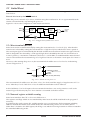
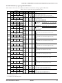
Comparison table between new and previous number
S1C63 Family processors
S1C63 Family peripheral products
Previous No.
New No.
Previous No.
New No.
E0C63158
E0C63256
E0C63358
E0C63P366
E0C63404
E0C63406
E0C63408
E0C63F408
E0C63454
E0C63455
E0C63458
E0C63466
E0C63P466
S1C63158
S1C63256
S1C63358
S1C6P366
S1C63404
S1C63406
S1C63408
S1C6F408
S1C63454
S1C63455
S1C63458
S1C63466
S1C6P466
E0C63467
E0C63557
E0C63558
E0C63567
E0C63F567
E0C63658
E0C63666
E0C63F666
E0C63A08
E0C63B07
E0C63B08
E0C63B58
S1C63467
S1C63557
S1C63558
S1C63567
S1C6F567
S1C63658
S1C63666
S1C6F666
S1C63A08
S1C63B07
S1C63B08
S1C63B58
Previous No.
E0C5250
E0C5251
New No.
S1C05250
S1C05251
Comparison table between new and previous number of development tools
Development tools for the S1C63 Family
Development tools for the S1C63/88 Family
Previous No.
New No.
Previous No.
New No.
ADP63366
ADP63466
ASM63
GAM63001
ICE63
PRC63001
PRC63002
PRC63004
PRC63005
PRC63006
PRC63007
URS63366
S5U1C63366X
S5U1C63466X
S5U1C63000A
S5U1C63000G
S5U1C63000H1
S5U1C63001P
S5U1C63002P
S5U1C63004P
S5U1C63005P
S5U1C63006P
S5U1C63007P
S5U1C63366Y
ADS00002
GWH00002
URM00002
S5U1C88000X1
S5U1C88000W2
S5U1C88000W1
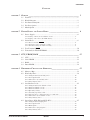
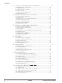
CONTENTS
CONTENTS
CHAPTER
1 OUTLINE ________________________________________________ 1
1.1
1.2
1.3
1.4
1.5
CHAPTER
Features ......................................................................................................... 1
Block Diagram .............................................................................................. 2
Pin Layout Diagram ..................................................................................... 3
Pin Description ............................................................................................. 4
Mask Option .................................................................................................. 5
2 POWER SUPPLY AND INITIAL RESET ____________________________ 6
2.1
Power Supply ................................................................................................ 6
2.1.1 Voltage <VD1> for oscillation circuit ........................................................ 7
2.1.2 Voltage <VC1–VC5> for LCD driving ........................................................ 7
2.2
Initial Reset ................................................................................................... 8
2.2.1 Reset terminal (RESET) ............................................................................. 8
2.2.2 Internal register at initial resetting ............................................................ 8
2.2.3 Terminal settings at initial resetting .......................................................... 9
2.3
2.4
CHAPTER
3 CPU, PROM, RAM ______________________________________ 11
3.1
3.2
3.3
3.4
CHAPTER
Test Terminal (TEST) ................................................................................... 10
Terminals for Flash EEPROM ..................................................................... 10
CPU .............................................................................................................. 11
Code PROM ................................................................................................. 11
RAM ............................................................................................................. 11
Data PROM .................................................................................................. 12
4 PERIPHERAL CIRCUITS AND OPERATION __________________________ 13
4.1
4.2
Memory Map ................................................................................................ 13
Watchdog Timer ........................................................................................... 19
4.2.1 Configuration of watchdog timer .............................................................. 19
4.2.2 Interrupt function ...................................................................................... 19
4.2.3 I/O memory of watchdog timer ................................................................. 20
4.2.4 Programming notes ................................................................................... 20
4.3
Oscillation Circuit ....................................................................................... 21
4.3.1 Configuration of oscillation circuit .......................................................... 21
4.3.2 OSC1 oscillation circuit ............................................................................ 21
4.3.3 OSC3 oscillation circuit ............................................................................ 21
4.3.4 Operating voltage ...................................................................................... 22
4.3.5 Switching operating clock ......................................................................... 22
4.3.6 Clock frequency and instruction execution time ....................................... 22
4.3.7 I/O memory of oscillation circuit .............................................................. 23
4.3.8 Programming notes ................................................................................... 24
4.4
Input Ports (K00–K03 and K10–K13) ......................................................... 25
4.4.1 Configuration of input ports ..................................................................... 25
4.4.2 Interrupt function ...................................................................................... 25
4.4.3 Mask option ............................................................................................... 26
4.4.4 I/O memory of input ports ......................................................................... 27
4.4.5 Programming notes ................................................................................... 29
S1C6P466 TECHNICAL MANUAL
EPSON
i
CONTENTS
4.5
Output Ports (R00–R03, R10–R13 and R20–R23) ...................................... 30
4.5.1 Configuration of output ports ................................................................... 30
4.5.2 Mask option ............................................................................................... 30
4.5.3 High impedance control ............................................................................ 31
4.5.4 Special output ............................................................................................ 31
4.5.5 I/O memory of output ports ....................................................................... 33
4.5.6 Programming notes ................................................................................... 35
4.6
I/O Ports (P00–P03, P10–P13 and P20–P23) ............................................ 36
4.6.1 Configuration of I/O ports ........................................................................ 36
4.6.2 Mask option ............................................................................................... 36
4.6.3 I/O control registers and input/output mode ............................................ 37
4.6.4 Pull-up during input mode ........................................................................ 37
4.6.5 Special outputs (CL, FR) ........................................................................... 38
4.6.6 I/O memory of I/O ports ............................................................................ 39
4.6.7 Programming notes ................................................................................... 42
4.7
LCD Driver (COM0–COM16, SEG0–SEG59) ........................................... 43
4.7.1 Configuration of LCD driver .................................................................... 43
4.7.2 Power supply for LCD driving .................................................................. 43
4.7.3 Mask option ............................................................................................... 43
4.7.4 LCD display control (ON/OFF) and switching of duty ............................ 44
4.7.5 Display memory ......................................................................................... 46
4.7.6 LCD contrast adjustment .......................................................................... 47
4.7.7 I/O memory of LCD driver ........................................................................ 48
4.7.8 Programming notes ................................................................................... 50
4.8
Clock Timer .................................................................................................. 51
4.8.1 Configuration of clock timer ..................................................................... 51
4.8.2 Data reading and hold function ................................................................ 51
4.8.3 Interrupt function ...................................................................................... 52
4.8.4 I/O memory of clock timer ........................................................................ 53
4.8.5 Programming notes ................................................................................... 54
4.9
Stopwatch Timer ........................................................................................... 55
4.9.1 Configuration of stopwatch timer ............................................................. 55
4.9.2 Count-up pattern ....................................................................................... 55
4.9.3 Interrupt function ...................................................................................... 56
4.9.4 I/O memory of stopwatch timer ................................................................ 57
4.9.5 Programming notes ................................................................................... 58
4.10 Programmable Timer ................................................................................... 59
4.10.1 Configuration of programmable timer .................................................... 59
4.10.2 Setting of initial value and counting down ............................................. 60
4.10.3 Counter mode .......................................................................................... 61
4.10.4 Setting of input clock in timer mode ....................................................... 62
4.10.5 Interrupt function .................................................................................... 63
4.10.6 Setting of TOUT output ........................................................................... 63
4.10.7 Transfer rate setting for serial interface ................................................ 64
4.10.8 I/O memory of programmable timer ....................................................... 65
4.10.9 Programming notes ................................................................................. 70
4.11 Serial Interface (SIN, SOUT, SCLK, SRDY) ................................................ 71
4.11.1 Configuration of serial interface ............................................................ 71
4.11.2 Mask option ............................................................................................. 72
4.11.3 Master mode and slave mode of serial interface .................................... 72
4.11.4 Data input/output and interrupt function ............................................... 73
4.11.5 I/O memory of serial interface ................................................................ 75
4.11.6 Programming notes ................................................................................. 78
ii
EPSON
S1C6P466 TECHNICAL MANUAL
CONTENTS
4.12 Sound Generator .......................................................................................... 79
4.12.1 Configuration of sound generator .......................................................... 79
4.12.2 Mask option ............................................................................................. 79
4.12.3 Control of buzzer output .......................................................................... 79
4.12.4 Setting of buzzer frequency and sound level ........................................... 80
4.12.5 Digital envelope ...................................................................................... 81
4.12.6 One-shot output ....................................................................................... 82
4.12.7 I/O memory of sound generator .............................................................. 83
4.12.8 Programming notes ................................................................................. 85
4.13 SVD (Supply Voltage Detection) Circuit ...................................................... 86
4.13.1 Configuration of SVD circuit .................................................................. 86
4.13.2 Mask option ............................................................................................. 86
4.13.3 SVD operation ......................................................................................... 86
4.13.4 I/O memory of SVD circuit ...................................................................... 87
4.13.5 Programming notes ................................................................................. 88
4.14 Interrupt and HALT ..................................................................................... 89
4.14.1 Interrupt factor ........................................................................................ 91
4.14.2 Interrupt mask ......................................................................................... 92
4.14.3 Interrupt vector ....................................................................................... 92
4.14.4 I/O memory of interrupt .......................................................................... 93
4.14.5 Programming notes ................................................................................. 95
CHAPTER
5 PROM PROGRAMMING AND OPERATING MODE ____________________ 96
5.1
5.2
Configuration of PROM Programmer ......................................................... 96
Operating Mode ........................................................................................... 98
5.2.1 Normal operation mode ............................................................................ 98
5.2.2 Serial programming mode ......................................................................... 98
5.2.3 Parallel programming mode ..................................................................... 99
CHAPTER
6 DIFFERENCES FROM MASK ROM MODELS ______________________ 100
6.1
6.2
6.3
6.4
6.5
6.6
CHAPTER
7 SUMMARY OF NOTES ______________________________________ 104
7.1
7.2
7.3
CHAPTER
Mask Option ................................................................................................ 100
Power Supply .............................................................................................. 101
PROM, RAM ............................................................................................... 102
Input/Output Ports and LCD Driver ........................................................... 102
Oscillation Circuit ...................................................................................... 102
SVD Circuit ................................................................................................. 103
Notes for Low Current Consumption .......................................................... 104
Summary of Notes by Function ................................................................... 105
Precautions on Mounting ........................................................................... 109
8 BASIC EXTERNAL WIRING DIAGRAM ___________________________ 111
S1C6P466 TECHNICAL MANUAL
EPSON
iii
CONTENTS
CHAPTER
9 ELECTRICAL CHARACTERISTICS _______________________________ 113
9.1
9.2
9.3
9.4
9.5
9.6
9.7
9.8
CHAPTER
Absolute Maximum Rating .......................................................................... 113
Recommended Operating Conditions ......................................................... 113
DC Characteristics ..................................................................................... 114
Analog Circuit Characteristics and Power Current Consumption ............ 115
Oscillation Characteristics ......................................................................... 117
Serial Interface AC Characteristics ........................................................... 118
Timing Chart ............................................................................................... 119
Characteristics Curves (reference value) ................................................... 120
10 PACKAGE _______________________________________________ 125
10.1 Plastic Package ........................................................................................... 125
10.2 Ceramic Package for Test Samples ............................................................. 127
CHAPTER
11 PAD LAYOUT ____________________________________________ 129
11.1 Diagram of Pad Layout ............................................................................... 129
11.2 Pad Coordinates .......................................................................................... 130
APPENDIX
A PROM PROGRAMMING ___________________________________ 131
A.1 Outline of Writing Tools .............................................................................. 131
A.2 Serial Programming (S1C88/S1C63 Serial Connector) ............................ 132
A.2.1 Serial programming environment (S1C88/S1C63 Serial Connector) .... 132
A.2.2 System connection and setup for serial programming
(S1C88/S1C63 Serial Connector) ........................................................... 133
A.2.3 Serial programming procedure (S1C88/S1C63 Serial Connector) ........ 134
A.2.4 Connection diagram for serial programming
(S1C88/S1C63 Serial Connector) ........................................................... 136
A.3 Parallel Programming ................................................................................ 138
A.3.1 Parallel programming environment ......................................................... 138
A.3.2 System connection and setup for parallel programming ........................ 139
A.3.3 Parallel programming procedure ............................................................ 140
A.4 Universal ROM Writer II (S5U1C88000W1) Specifications ...................... 143
A.4.1 Outline of Universal ROM Writer II specifications ................................ 143
A.4.2 Detailed description of the Universal ROM Writer II commands .......... 144
A.4.3 List of Universal ROM Writer II commands ........................................... 152
A.4.4 Universal ROM Writer II error messages ............................................... 153
A.5 Flash EEPROM Programming Notes ......................................................... 154
APPENDIX B S5U1C63000P MANUAL
(PERIPHERAL CIRCUIT BOARD FOR S1C63404/454/455/458/466/P466) ____ 155
B.1 Names and Functions of Each Part ............................................................ 155
B.2 Connecting to the Target System ................................................................ 158
B.3 Usage Precautions ...................................................................................... 160
B.3.1 Operational precautions .......................................................................... 160
B.3.2 Differences with the actual IC ................................................................. 160
iv
EPSON
S1C6P466 TECHNICAL MANUAL
CHAPTER 1: OUTLINE
CHAPTER
1 OUTLINE
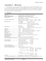
The S1C6P466 is a microcomputer which has a high-performance 4-bit CPU S1C63000 as the core
CPU, rewritable Flash EEPROM (hereinafter called PROM), RAM, dot-matrix LCD driver, serial interface
and timers. The S1C6P466 has a built-in large capacity PROM (16K × 13 bits) and RAM (5K × 4 bits) that
are compatible with the S1C63454, S1C63458 and S1C63466, it can therefore be used as an MTP (MultiTime Programming) for program development.
1.1 Features
4-bit parallel processing CMOS LSI, S1C63000
32.768 kHz (Typ.) crystal oscillation circuit
4 MHz (Max.) ceramic oscillation circuit
Basic instruction: 46 types (411 instructions with all)
Addressing mode: 8 types
Instruction execution time ................... During operation at 32.768 kHz: 61 µsec 122 µsec 183 µsec
During operation at 4 MHz:
0.5 µsec
1 µsec 1.5 µsec
PROM capacity ................................... Code PROM:
16,384 words × 13 bits
Data PROM:
2,048 words × 4 bits
Programming method: Parallel or serial programming
(exclusive PROM writer is used)
Rewriting:
100 times (Max.)
RAM capacity ...................................... Data memory:
5,120 words × 4 bits
Display memory:
1,020 bits (240 words × 4 bits + 60 × 1 bit)
Input port ............................................. 8 bits
(with pull-up resistors)
Output port .......................................... 12 bits
(2 special outputs are available ∗1)
I/O port ................................................ 12 bits
(2 special outputs and 4 serial I/O are available ∗1)
Serial interface .................................... 1 port
(8-bit clock synchronous system)
LCD driver ........................................... 60 segments × 8, 16 or 17 commons (∗1)
Time base counter .............................. 2 systems (Clock timer, stopwatch timer)
Programmable timer ........................... Built-in, 2 inputs × 8 bits, with event counter function
Watchdog timer ................................... Built-in
Sound generator ................................. With envelope and 1-shot output functions
Supply voltage detection (SVD) circuit .. 1 external voltage detection level (1.05 V)
and 7 internal voltage detection levels (2.70 V to 3.30 V)
External interrupt ................................ Input port interrupt:
2 systems
Internal interrupt ................................. Clock timer interrupt:
4 systems
Stopwatch timer interrupt:
2 systems
Programmable timer interrupt: 2 systems
Serial interface interrupt:
1 system
Power supply voltage ......................... 2.7 V to 5.5 V
Operating temperature range ............. -20°C to 70°C
Current consumption (Typ.) ................ Single clock (OSC1: Crystal oscillation):
During HALT (32 kHz)
3.0 V ±10% 2.5 µA (LCD OFF)
5.0 V ±10% 3.0 µA (LCD OFF)
During operation (32 kHz) 3.0 V ±10% 90 µA
5.0 V ±10% 300 µA
Twin clock:
During operation (4 MHz) 3.0 V ±10% 1 mA
5.0 V ±10% 2.3 mA
Package .............................................. QFP8-144pin (∗3), QFP17-144pin (plastic ∗2) or chip
Core CPU ............................................
OSC1 oscillation circuit ......................
OSC3 oscillation circuit ......................
Instruction set .....................................
∗1: Can be selected with software. ∗2: 128-pin package is not available. *3: The QFP8-144pin package does not
support parallel programming using an adapter socket. Only serial programming can be performed.
S1C6P466 TECHNICAL MANUAL
EPSON
1
CHAPTER 1: OUTLINE
1.2 Block Diagram
Code PROM
16,384 words × 13 bits
PROM
Programmer
VDDF
VEPEXT
RSTOUT
SPRG
CLKIN
TXD
RXD
SCLK
Data PROM
Interrupt
Generator
RAM
COM0–16
SEG0–59
VDD
VC1–5
CA–CF
VD1
VSS
VREF
SVD
BZ
RESET
Core CPU S1C63000
2,048 words × 4 bits
OSC1
OSC2
OSC3
OSC4
System Reset
Control
5,120 words × 4 bits
Stopwatch
Timer
OSC
Clock
Timer
LCD Driver
Programmable
Timer/Counter
60 SEG × 17 COM
Input Port
K00–K03
K10–K13
TEST
Power
Controller
Serial Interface
SVD
I/O Port
P00–P03
P10–P13
P20–P23
Sound
Generator
Output Port
R00–R03
R10–R13
R20–R23
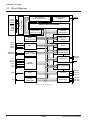
Fig. 1.2.1 Block diagram
2
EPSON
S1C6P466 TECHNICAL MANUAL
CHAPTER 1: OUTLINE
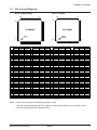
1.3 Pin Layout Diagram
QFP8-144pin (Note)
QFP17-144pin
108
108
73
72
109
72
109
73
S1C6P466
S1C6P466
INDEX
INDEX
37
144
1
No.
1
2
3
4
5
6
7
8
9
10
11
12
13
14
15
16
17
18
19
20
21
22
23
24
25
26
27
28
29
30
31
32
33
34
35
36
S1C63458
SEG13
SEG12
SEG11
SEG10
SEG9
SEG8
SEG7
SEG6
SEG5
SEG4
SEG3
SEG2
SEG1
SEG0
COM7
COM6
COM5
COM4
N.C.
COM3
COM2
COM1
COM0
BZ
VSS
OSC1
OSC2
VD1
OSC3
OSC4
VDD
RESET
TEST
VREF
N.C.
N.C.
Pin name
S1C63466 S1C6P466
SEG13
SEG13
SEG12
SEG12
SEG11
SEG11
SEG10
SEG10
SEG9
SEG9
SEG8
SEG8
SEG7
SEG7
SEG6
SEG6
SEG5
SEG5
SEG4
SEG4
SEG3
SEG3
SEG2
SEG2
SEG1
SEG1
SEG0
SEG0
COM7
COM7
COM6
COM6
COM5
COM5
COM4
COM4
N.C.
N.C.
COM3
COM3
COM2
COM2
COM1
COM1
COM0
COM0
BZ
BZ
VSS
VSS
OSC1
OSC1
OSC2
OSC2
VD1
VD1
OSC3
OSC3
OSC4
OSC4
VDD
VDD
RESET
RESET
TEST
TEST
VREF
VREF
N.C.
CLKIN
N.C.
SCLK
1
36
No.
37
38
39
40
41
42
43
44
45
46
47
48
49
50
51
52
53
54
55
56
57
58
59
60
61
62
63
64
65
66
67
68
69
70
71
72
S1C63458
N.C.
N.C.
R23
R22
R21
R20
R13
R12
R11
R10
R03
R02
R01
R00
P23
P22
P21
P20
P13
P12
P11
P10
P03
P02
P01
P00
K13
K12
K11
K10
K03
K02
K01
K00
N.C.
N.C.
37
144
Pin name
S1C63466 S1C6P466
N.C.
RXD
N.C.
TXD
R23
R23
R22
R22
R21
R21
R20
R20
R13
R13
R12
R12
R11
R11
R10
R10
R03
R03
R02
R02
R01
R01
R00
R00
P23
P23
P22
P22
P21
P21
P20
P20
P13
P13
P12
P12
P11
P11
P10
P10
P03
P03
P02
P02
P01
P01
P00
P00
K13
K13
K12
K12
K11
K11
K10
K10
K03
K03
K02
K02
K01
K01
K00
K00
N.C.
SPRG
N.C.
N.C.
No.
73
74
75
76
77
78
79
80
81
82
83
84
85
86
87
88
89
90
91
92
93
94
95
96
97
98
99
100
101
102
103
104
105
106
107
108
S1C63458
N.C.
SVD
VC1
VC2
VC3
VC4
VC5
CF
CE
CD
CC
CB
CA
COM8
COM9
COM10
COM11
COM12
COM13
COM14
COM15
COM16
SEG59
SEG58
SEG57
SEG56
SEG55
SEG54
SEG53
SEG52
SEG51
SEG50
SEG49
SEG48
N.C.
N.C.
36
Pin name
S1C63466 S1C6P466
N.C.
VDDF
SVD
SVD
VC1
VC1
VC2
VC2
VC3
VC3
VC4
VC4
VC5
VC5
CF
CF
CE
CE
CD
CD
CC
CC
CB
CB
CA
CA
COM8
COM8
COM9
COM9
COM10
COM10
COM11
COM11
COM12
COM12
COM13
COM13
COM14
COM14
COM15
COM15
COM16
COM16
SEG59
SEG59
SEG58
SEG58
SEG57
SEG57
SEG56
SEG56
SEG55
SEG55
SEG54
SEG54
SEG53
SEG53
SEG52
SEG52
SEG51
SEG51
SEG50
SEG50
SEG49
SEG49
SEG48
SEG48
N.C.
VEPEXT
N.C.
N.C.
No.
109
110
111
112
113
114
115
116
117
118
119
120
121
122
123
124
125
126
127
128
129
130
131
132
133
134
135
136
137
138
139
140
141
142
143
144
S1C63458
N.C.
SEG47
SEG46
SEG45
SEG44
SEG43
SEG42
SEG41
SEG40
SEG39
SEG38
SEG37
SEG36
SEG35
SEG34
SEG33
SEG32
SEG31
SEG30
SEG29
SEG28
SEG27
SEG26
SEG25
SEG24
SEG23
SEG22
SEG21
SEG20
SEG19
SEG18
SEG17
SEG16
SEG15
SEG14
N.C.
Pin name
S1C63466 S1C6P466
N.C.
RSTOUT
SEG47
SEG47
SEG46
SEG46
SEG45
SEG45
SEG44
SEG44
SEG43
SEG43
SEG42
SEG42
SEG41
SEG41
SEG40
SEG40
SEG39
SEG39
SEG38
SEG38
SEG37
SEG37
SEG36
SEG36
SEG35
SEG35
SEG34
SEG34
SEG33
SEG33
SEG32
SEG32
SEG31
SEG31
SEG30
SEG30
SEG29
SEG29
SEG28
SEG28
SEG27
SEG27
SEG26
SEG26
SEG25
SEG25
SEG24
SEG24
SEG23
SEG23
SEG22
SEG22
SEG21
SEG21
SEG20
SEG20
SEG19
SEG19
SEG18
SEG18
SEG17
SEG17
SEG16
SEG16
SEG15
SEG15
SEG14
SEG14
N.C.
N.C.
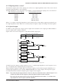
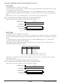
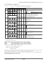
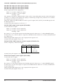
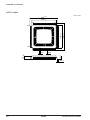
Fig. 1.3.1 Pin layout diagram
Notes: • The pin layout diagram of the both package is same.
• The QFP8-144pin package does not support parallel programming using an adapter socket.
Only serial programming can be performed.
S1C6P466 TECHNICAL MANUAL
EPSON
3
CHAPTER 1: OUTLINE
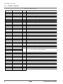
1.4 Pin Description
Table 1.4.1 Pin description
Pin name
VDD
VSS
VD1
VC1–VC5
VREF
CA–CF
OSC1
OSC2
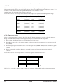
OSC3
OSC4
K00–K03
K10, K11
K12
K13
P00–P03
P10–P13
P20
P21
P22
P23
R00
R01
R02
R03
R10–R13
R20–R23
COM0, COM1
COM2–COM14
COM15, COM16
SEG0–SEG59
BZ
SVD
RESET
TEST
TXD
RXD
SCLK
CLKIN
SPRG
RSTOUT
VDDF
VEPEXT
4
Pin No.
31
25
28
75–79
34
85–80
26
27
29
30
70–67
66,65
64
63
62–59
58–55
54
53
52
51
50
49
48
47
46–43
42–39
23,22
21,20,18–15,86–92
93,94
14–1,143–110,106–95
24
74
32
33
38
37
36
35
71
109
73
107
In/Out
–
–
–
–
O
–
I
O
I
O
I
I
I
I
I/O
I/O
I/O
I/O
I/O
I/O
O
O
O
O
O
O
O
O
O
I
I
I
O
I
I/O
I
I
O
–
I/O
Function
Power (+) supply pin
Power (–) supply pin
Oscillation/internal logic system regulated voltage output pin
LCD system power supply pin (1/4 bias generated internally)
LCD system power supply testing pin
LCD system boosting/reducing capacitor connecting pin
Crystal oscillation input pin
Crystal oscillation output pin
Ceramic oscillation input pin
Ceramic oscillation output pin
Input port
Input port
Input port
Input port
I/O port
I/O port (switching to serial I/F input/output is possible by software)
I/O port
I/O port
I/O port (switching to CL signal output is possible by software)
I/O port (switching to FR signal output is possible by software)
Output port
Output port
Output port(switching to TOUT signal output is possible by software)
Output port(switching to FOUT signal output is possible by software)
Output port
Output port
LCD common output pin
(1/8, 1/16, 1/17 duty can be selected by software)
LCD segment output pin
Sound output pin
SVD external voltage input pin
Initial reset input pin
Testing input pin
Serial data output pin for Flash programming
Serial data input pin for Flash programming
Serial clock input/output pin for Flash programming
Clock input pin for Flash programming
Flash programming control pin
Flash test pin (N.C. in normal operation)
Flash power (+) supply pin (connect to VDD in normal operation)
Flash test pin (N.C. in normal operation)
EPSON
S1C6P466 TECHNICAL MANUAL
CHAPTER 1: OUTLINE
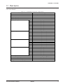
1.5 Mask Option
The mask options provided for the S1C63454/63458/63466 are fixed as follows in the S1C6P466, so they
cannot be selected.
Table 1.5.1 S1C6P466 mask option configuration
Mask option
Setting
OSC1 oscillation circuit
Crystal oscillation (32.768 kHz)
OSC3 oscillation circuit
Use <ceramic> or Not use
Multiple key entry reset combination
Not use
Multiple key entry reset time authorization
Not use
Input port pull-up resistor
K00
With pull-up resistor
K01
With pull-up resistor
K02
With pull-up resistor
K03
With pull-up resistor
K10
With pull-up resistor
K11
With pull-up resistor
K12
With pull-up resistor
K13
With pull-up resistor
Output port specification
R00
Complementary
R01
Complementary
R02
Complementary
R03
Complementary
R1x
Complementary
R2x
Complementary
I/O port specification
P0x
Complementary
P1x
Complementary
P20
Complementary
P21
Complementary
P22
Complementary
P23
Complementary
I/O port pull-up resistor
P0x
With pull-up resistor
P1x
With pull-up resistor
P20
With pull-up resistor
P21
With pull-up resistor
P22
With pull-up resistor
P23
With pull-up resistor
LCD drive power
Internal power supply
Serial interface polarity
Negative polarity
SVD circuit external voltage detection
Use
Sound generator buzzer output specification
Positive polarity
S1C6P466 TECHNICAL MANUAL
EPSON
5
CHAPTER 2: POWER SUPPLY AND INITIAL RESET
CHAPTER
2 POWER SUPPLY AND INITIAL RESET
2.1 Power Supply
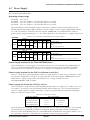
The S1C6P466 operating power voltage is as follows:
Table 2.1.1 Operating power voltage
Operating mode
MCU normal operation mode
PROM programming mode
Operating power voltage
2.7 V–5.5 V
5.0 V ±10%
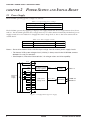
The S1C6P466 operates by applying a single power supply within the above range between VDD/VDDF
and VSS. The S1C6P466 generates the voltage necessary for all the internal circuits by the built-in power
supply circuits shown in Table 2.1.2. Supply the same voltage level as VDD to the VDDF terminal from
outside the IC.
Table 2.1.2 Power supply circuits
Circuit
Power supply circuit
Oscillation circuit Oscillation system voltage regulator
LCD driver
LCD system voltage circuit
Output voltage
VD1
VC1–VC5
Notes: • Do not drive external loads with the output voltage from the internal power supply circuits.
• The internal LCD system voltage circuit (1/4 bias) is always used in the S1C6P466, connect
between VC3 and VC2 terminals.
• See Chapter 9, "Electrical Characteristics", for voltage values and drive capability.
V DD
VDDF
VD1
External
power
supply
+
V C1
V C2
V C3
V C4
V C5
CA
CB
CC
CD
CE
CF
Oscillation system
voltage regulator
LCD system
voltage circuit
VD1
V C1 – V C5
Oscillation
circuit
LCD driver
OSC1–4
COM0–16
SEG0–59
V SS
Fig. 2.1.1 Configuration of power supply
6
EPSON
S1C6P466 TECHNICAL MANUAL
CHAPTER 2: POWER SUPPLY AND INITIAL RESET
2.1.1 Voltage <VD1> for oscillation circuit
VD1 is the operating voltage for the oscillation circuit, and is generated by the oscillation system voltage
regulator for stabilizing the oscillation.
In the S1C63454/63458/63466, it is necessary to switch the VD1 voltage level according to the oscillation
circuit and operating frequency by controlling the voltage regulator. In the S1C6P466, the VD1 voltage
level is fixed, so software control for switching the VD1 level does not affect the actual output voltage.
Refer to Chapter 6, "Differences from Mask ROM Models", for details.
2.1.2 Voltage <VC1–VC5> for LCD driving
VC1–VC5 are the LCD drive voltages generated by the LCD system voltage circuit. The built-in LCD
system voltage circuit generates four voltages (1/4 bias) VC1, VC2, VC4 and VC5 (excluding VC3). These
four output voltages can only be supplied to the externally expanded LCD driver.
The LCD system voltage circuit generates VC1 or VC2 with the voltage regulator built-in, and generates
three other voltages by boosting or reducing the voltage of VC1 or VC2. Table 2.1.2.1 shows the VC1, VC2,
VC4 and VC5 voltage values and boost/reduce status.
Table 2.1.2.1 LCD drive voltage when generated internally
LCD drive voltage
VC1 (0.975–1.2 V)
VC1 standard
VC1 (regulated)
VC2 standard
1/2 × VC2
VC2 (1.950–2.4 V)
VC4 (2.925–3.6 V)
VC5 (3.900–4.8 V)
2 × VC1
3 × VC1
VC2 (regulated)
3/2 × VC2
4 × VC1
2 × VC2
Note: The LCD drive voltage can be adjusted by the software (see Section 4.7.6). Values in the above
table are typical values.
Either the VC1 or VC2 used for the standard is selected according to the supply voltage by the software.
In the S1C6P466, either can be selected regardless of the supply voltage level since the minimum operating voltage is 2.7 V.
The VC2 standard improves the display quality and reduces current consumption, note, however, the VC1
standard must be set in the mask ROM model if the power supply voltage VDD is 2.6 V or less.
Refer to Section 4.7, "LCD Driver", for control of the LCD drive voltage.
S1C6P466 TECHNICAL MANUAL
EPSON
7
CHAPTER 2: POWER SUPPLY AND INITIAL RESET
2.2 Initial Reset
To initialize the S1C6P466 circuits, initial reset must be executed. The S1C6P466 supports the initial reset
factor below.
External initial reset by the RESET terminal
When the power is turned on, be sure to initialize using the reset function. It is not guaranteed that the
circuits are initialized by only turning the power on.
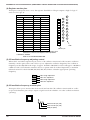
Figure 2.2.1 shows the configuration of the initial reset circuit.
OSC1
OSC2
OSC1
oscillation
circuit
1 Hz
Divider
2 Hz
VDD
Noise
reject
circuit
R
Internal
initial
reset
Q
S
RESET
Fig. 2.2.1 Configuration of initial reset circuit
2.2.1 Reset terminal (RESET)
Initial reset can be executed externally by setting the reset terminal to a low level (VSS). After that the
initial reset is released by setting the reset terminal to a high level (VDD) and the CPU starts operation.
The reset input signal is maintained by the RS latch and becomes the internal initial reset signal. The RS
latch is designed to be released by a 2 Hz signal (high) that is divided by the OSC1 clock. Therefore in
normal operation, a maximum of 250 msec (when fOSC1 = 32.768 kHz) is needed until the internal initial
reset is released after the reset terminal goes to high level. Be sure to maintain a reset input of 0.1 msec or
more.
However, when turning the power on, the reset terminal should be set at a low level as in the timing
shown in Figure 2.2.1.1.
2.7 V
VDD
2.0 msec or more
RESET
0.5•VDD
0.1•VDD or less (low level)
Power on
Fig. 2.2.1.1 Initial reset at power on
The reset terminal should be set to 0.1•VDD or less (low level) until the supply voltage becomes 2.7 V or
more. After that, a level of 0.5•VDD or less should be maintained more than 2.0 msec.
In the S1C6P466, a low level input to the reset terminal initializes some analog circuits as well as the
internal logic. At this time, 10 µA or more current is consumed as the bias current.
2.2.2 Internal register at initial resetting
Initial reset initializes the CPU as shown in Table 2.2.2.1.
The registers and flags which are not initialized by initial reset should be initialized in the program if
necessary.
In particular, the stack pointers SP1 and SP2 must be set as a pair because all the interrupts including
NMI are masked after initial reset until both the SP1 and SP2 stack pointers are set with software.
When data is written to the EXT register, the E flag is set and the following instruction will be executed in
the extended addressing mode.
8
EPSON
S1C6P466 TECHNICAL MANUAL
CHAPTER 2: POWER SUPPLY AND INITIAL RESET
If an instruction which does not permit extended operation is used as the following instruction, the
operation is not guaranteed. Therefore, do not write data to the EXT register for initialization only.
Refer to the "S1C63000 Core CPU Manual" for extended addressing and usable instructions.
Table 2.2.2.1 Initial values
CPU core
Name
Data register A
Data register B
Extension register EXT
Index register X
Index register Y
Symbol
Number of bits
Setting value
A
B
4
4
Undefined
Undefined
EXT
X
8
16
Undefined
Undefined
Y
16
Undefined
Program counter
Stack pointer SP1
PC
SP1
16
8
0110H
Undefined
Stack pointer SP2
Zero flag
SP2
Z
8
1
Undefined
Undefined
Carry flag
Interrupt flag
Extension flag
C
I
E
1
1
1
Undefined
0
0
Queue register
Q
16
Undefined
Name
Peripheral circuits
Number of bits
RAM
Display memory
Other pheripheral circuits
Setting value
4
4
–
Undefined
Undefined
∗
∗ See Section 4.1, "Memory Map".
2.2.3 Terminal settings at initial resetting
The output port (R) terminals and I/O port (P) terminals are shared with special output terminals and
input/output terminals of the serial interface. These functions are selected by the software. At initial
reset, these terminals are set to the general purpose output port terminals and I/O port terminals. Set
them according to the system in the initial routine. In addition, take care of the initial status of output
terminals when designing a system.
Table 2.2.3.1 shows the list of the shared terminal settings.
Table 2.2.3.1 List of shared terminal settings
Terminal
name
R00
R01
R02
R03
R10–R13
Terminal status
at initial reset
R00 (High output)
R01 (High output)
R02 (High output)
R03 (High output)
R10–R13 (High output)
Special output
TOUT FOUT CL
FR
TOUT
FOUT
R20–R23 R20–R23 (High output)
P00–P03 P00–P03 (Input & Pull-up)
P10
P10 (Input & Pull-up)
P11
P12
P13
P11 (Input & Pull-up)
P12 (Input & Pull-up)
P13 (Input & Pull-up)
P20
P21
P22
P20 (Input & Pull-up)
P21 (Input & Pull-up)
P22 (Input & Pull-up)
P23
P23 (Input & Pull-up)
Serial I/F
Master
Slave
SIN(I)
SIN(I)
SOUT(O) SOUT(O)
SCLK(O) SCLK(I)
SRDY(O)
CL
FR
For setting procedure of the functions, see explanations for each of the peripheral circuits.
S1C6P466 TECHNICAL MANUAL
EPSON
9
CHAPTER 2: POWER SUPPLY AND INITIAL RESET
2.3 Test Terminal (TEST)
This is the terminal used for the factory inspection of the IC. During normal operation, connect the TEST
terminal to VDD.
2.4 Terminals for Flash EEPROM
The S1C6P466 has the following terminals used for writing data to the Flash EEPROM and for factory
testing.
VDDF:
SPRG:
SCLK:
RXD:
TXD:
CLKIN:
RSTOUT:
VEPEXT:
Power supply (+) terminal for Flash EEPROM
Flash EEPROM programming control terminal
Clock input/output terminal for Flash EEPROM serial programming
Data input terminal for Flash EEPROM serial programming
Data output terminal for Flash EEPROM serial programming
Flash EEPROM write-control clock input terminal
Test-signal monitor terminal
Test-signal monitor terminal
The above terminals should be set up according to the operating mode. Refer to Chapter 5, "PROM
Programmer and Operating Mode", for details.
10
EPSON
S1C6P466 TECHNICAL MANUAL
CHAPTER 3: CPU, PROM, RAM
CHAPTER
3 CPU, PROM, RAM
3.1 CPU
The S1C6P466 has a 4-bit core CPU S1C63000 built-in as its CPU part.
Refer to the "S1C63000 Core CPU Manual" for the S1C63000.
Note: The SLP instruction cannot be used because the SLEEP operation is not assumed in the S1C6P466.
3.2 Code PROM
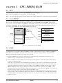
The built-in code PROM is a PROM for loading programs, and has a capacity of 16,384 steps × 13 bits.
The core CPU can linearly access the program space up to step FFFFH from step 0000H, however, the
program area of the S1C6P466 is step 0000H to step 3FFFH. The program start address after initial reset is
assigned to step 0110H. The non-maskable interrupt (NMI) vector and hardware interrupt vectors are
allocated to step 0100H and steps 0104H–010EH, respectively.
0000H
0000H
PROM
S1C6P466
program area
3FFFH
4000H
0100H
0104H
010EH
S1C63000 core CPU
program space
FFFFH
0110H
Program area
NMI vector
Hardware
interrupt vectors
Program start address
Program area
Unused area
13 bits
Fig. 3.2.1 Configuration of code PROM
3.3 RAM
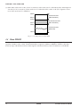
The RAM is a data memory for storing various kinds of data, and has a capacity of 5,120 words × 4 bits.
The RAM area is assigned to addresses 0000H to 13FFH on the data memory map. Addresses 0100H to
01FFH are 4-bit/16-bit data accessible areas and in other areas it is only possible to access 4-bit data.
When programming, keep the following points in mind.
(1) Part of the RAM area is used as a stack area for subroutine call and register evacuation, so pay
attention not to overlap the data area and stack area.
(2) The S1C63000 core CPU handles the stack using the stack pointer for 4-bit data (SP2) and the stack
pointer for 16-bit data (SP1).
16-bit data are accessed in stack handling by SP1, therefore, this stack area should be allocated to the
area where 4-bit/16-bit access is possible (0100H to 01FFH). The stack pointers SP1 and SP2 change
cyclically within their respective range: the range of SP1 is 0000H to 03FFH and the range of SP2 is
0000H to 00FFH. Therefore, pay attention to the SP1 value because it may be set to 0200H or more
exceeding the 4-bit/16-bit accessible range in the S1C6P466 or it may be set to 00FFH or less. Memory
accesses except for stack operations by SP1 are 4-bit data access.
After initial reset, all the interrupts including NMI are masked until both the stack pointers SP1 and
SP2 are set by software. Further, if either SP1 or SP2 is re-set when both are set already, the interrupts
including NMI are masked again until the other is re-set. Therefore, the settings of SP1 and SP2 must
be done as a pair.
S1C6P466 TECHNICAL MANUAL
EPSON
11
CHAPTER 3: CPU, PROM, RAM
(3) Subroutine calls use 4 words (for PC evacuation) in the stack area for 16-bit data (SP1). Interrupts use
4 words (for PC evacuation) in the stack area for 16-bit data (SP1) and 1 word (for F register evacuation) in the stack area for 4-bit data.
0000H
4-bit access area
(SP2 stack area)
00FFH
0100H
4/16-bit access area
(SP1 stack area)
01FFH
0200H
4-bit access area
(Data area)
13FFH
4 bits
Fig. 3.3.1 Configuration of data RAM
3.4 Data PROM
The data PROM is a PROM for loading various static data such as a character generator, and has a
capacity of 2,048 words × 4 bits. The data PROM is assigned to addresses 8000H to 87FFH on the data
memory map, and the data can be read using the same data memory access instructions as the RAM.
12
EPSON
S1C6P466 TECHNICAL MANUAL
CHAPTER 4: PERIPHERAL CIRCUITS AND OPERATION (Memory Map)
CHAPTER
4 PERIPHERAL CIRCUITS AND OPERATION
The peripheral circuits of S1C6P466 (timer, I/O, etc.) are interfaced with the CPU in the memory
mapped I/O method. Thus, all the peripheral circuits can be controlled by accessing the I/O memory on
the memory map using the memory operation instructions. The following sections explain the detailed
operation of each peripheral circuit.
4.1 Memory Map
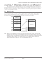
The S1C6P466 data memory consists of 5,120-word RAM, 2,048-word data PROM, 1,020-bit display
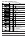
memory and 67-word peripheral I/O memory. Figure 4.1.1 shows the overall memory map of the
S1C6P466, and Tables 4.1.1(a)–(e) the peripheral circuits' (I/O space) memory maps.
0000H
RAM area
1400H
F000H
Unused area
Display memory area
8000H
F277H
Data PROM area
8800H
Unused area
Unused area
F000H
FF00H
FFFFH
FF00H
FF80H
FFC0H
FFFFH
I/O memory area
Peripheral I/O area
Unused area
Peripheral I/O area
Fig. 4.1.1 Memory map
Note: Memory is not implemented in unused areas within the memory map. Further, some non-implementation areas and unused (access prohibition) areas exist in the display memory area and the
peripheral I/O area. If the program that accesses these areas is generated, its operation cannot be
guaranteed. Refer to Section 4.7.5, "Display memory", for the display memory, and the I/O
memory maps shown in Tables 4.1.1 (a)–(e) for the peripheral I/O area.
S1C6P466 TECHNICAL MANUAL
EPSON
13
CHAPTER 4: PERIPHERAL CIRCUITS AND OPERATION (Memory Map)
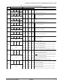
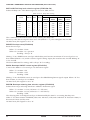
Table 4.1.1 (a) I/O memory map (FF00H–FF31H)
Address
Register
D3
D2
D1
D0
CLKCHG OSCC
0
VDC
R/W
R
R/W
FF00H
SVDS3 SVDS2 SVDS1 SVDS0
FF04H
R/W
0
0
SVDDT SVDON
FF05H
R
R/W
FOUTE
0
FOFQ1 FOFQ0
R/W
R
R/W
0
0
WDEN WDRST
FF06H
FF07H
R
SIK03
SIK02
R/W
W
SIK01
SIK00
FF20H
R/W
K03
K02
K01
K00
FF21H
R
KCP03 KCP02 KCP01 KCP00
FF22H
R/W
SIK13
SIK12
SIK11
SIK10
FF24H
R/W
K13
K12
K11
K10
FF25H
R
KCP13 KCP12 KCP11 KCP10
FF26H
R/W
R03HIZ R02HIZ R01HIZ R00HIZ
FF30H
R/W
R03
R02
R01
FF31H
R/W
R00
Comment
Name Init ∗1
1
0
CLKCHG
0
OSC3 OSC1 CPU clock switch
OSCC
OSC3 oscillation On/Off
0
On
Off
0 ∗3
Unused
– ∗2
VDC
0
1
0
CPU operating voltage switch
SVDS3
SVD criteria voltage setting
0
1
2
3
4
5
6
7
[SVDS3–0] 0
SVDS2
0
Voltage(V) 1.05(Ext) –
–
–
–
–
–
–
SVDS1
0
[SVDS3–0] 8
9
10
11
12
13
14
15
SVDS0
0
Voltage(V) –
–
2.80 2.90 3.00 3.10 3.20 3.30
0 ∗3
Unused
– ∗2
0 ∗3
– ∗2
Unused
SVDDT
0
Low Normal SVD evaluation data
SVDON
0
On
Off
SVD circuit On/Off
FOUTE
0
Enable Disable FOUT output enable
0 ∗3
Unused
– ∗2
FOUT
FOFQ1
0
1
2
[FOFQ1, 0]
0
3
frequency
Frequency fOSC1/64 fOSC1/8 fOSC1 fOSC3
FOFQ0
0
selection
0 ∗3
– ∗2
Unused
0 ∗3
– ∗2
Unused
WDEN
1
Enable Disable Watchdog timer enable
WDRST∗3 Reset Reset Invalid Watchdog timer reset (writing)
SIK03
0
Enable Disable
SIK02
0
Enable Disable
K00–K03 interrupt selection register
SIK01
0
Enable Disable
SIK00
0
Enable Disable
K03
– ∗2 High
Low
K02
– ∗2 High
Low
K00–K03 input port data
K01
– ∗2 High
Low
K00
– ∗2 High
Low
KCP03
1
KCP02
1
K00–K03 input comparison register
KCP01
1
KCP00
1
SIK13
0
Enable Disable
SIK12
0
Enable Disable
K10–K13 interrupt selection register
SIK11
0
Enable Disable
SIK10
0
Enable Disable
K13
– ∗2 High
Low
K12
– ∗2 High
Low
K10–K13 input port data
K11
– ∗2 High
Low
K10
– ∗2 High
Low
KCP13
1
KCP12
1
K10–K13 input comparison register
KCP11
1
KCP10
1
High-Z Output R03 output high impedance control (FOUTE=0)
0
R03HIZ
FOUT output high impedance control (FOUTE=1)
High-Z Output R02 output high impedance control (PTOUT=0)
0
R02HIZ
TOUT output high impedance control (PTOUT=1)
High-Z Output R01 output high impedance control
0
R01HIZ
High-Z Output R00 output high impedance control
0
R00HIZ
R03
1
High
Low R03 output port data (FOUTE=0) Fix at "1" when FOUT is used
R02
1
High
Low R02 output port data (PTOUT=0) Fix at "1" when TOUT is used
R01
1
High
Low R01 output port data
R00
1
High
Low R00 output port data
Remarks
∗1 Initial value at initial reset
∗2 Not set in the circuit
∗3 Constantly "0" when being read
14
EPSON
S1C6P466 TECHNICAL MANUAL
CHAPTER 4: PERIPHERAL CIRCUITS AND OPERATION (Memory Map)
Table 4.1.1 (b) I/O memory map (FF32H–FF46H)
Address
Register
D3
D2
D1
0
0
0
FF32H
R
R13
R12
R11
FF33H
R/W
0
0
0
FF34H
R
R23
R22
R21
FF35H
R/W
IOC03
IOC02
IOC01
FF40H
R/W
PUL03
PUL02
PUL01
FF41H
R/W
P03
P02
P01
FF42H
R/W
IOC13
IOC12
IOC11
IOC10
R/W
PUL12
PUL11
High-Z
High
High
High
High
Output
Output
Output
Output
On
On
On
On
High
High
High
High
Output
IOC12
0
Output
IOC11
0
Output
IOC10
0
Output
PUL13
1
On
PUL12
1
On
PUL11
1
On
PUL10
1
On
P13
– ∗2
High
P12
– ∗2
High
P11
– ∗2
High
P10
– ∗2
High
Name
0 ∗3
R1HIZ
0 ∗3
0 ∗3
R/W
R1HIZ
R13
R10
R12
R11
R10
0 ∗3
R2HIZ
0 ∗3
0 ∗3
R/W
R2HIZ
R23
R20
R22
R21
R20
IOC03
IOC00
IOC02
IOC01
IOC00
PUL03
PUL00
PUL02
PUL01
PUL00
P03
P00
P02
P01
P00
IOC13
FF44H
PUL13
Init ∗1
– ∗2
– ∗2
– ∗2
0
1
1
1
1
– ∗2
– ∗2
– ∗2
0
1
1
1
1
0
0
0
0
1
1
1
1
– ∗2
– ∗2
– ∗2
– ∗2
0
D0
PUL10
1
High-Z
High
High
High
High
FF45H
R/W
P13
P12
P11
FF46H
R/W
S1C6P466 TECHNICAL MANUAL
P10
0
Comment
Unused
Unused
Unused
Output R1 output high impedance control
Low
Low
R10–R13 output port data
Low
Low
Unused
Unused
Unused
Output R2 output high impedance control
Low
Low
R20–R23 output port data
Low
Low
Input
Input
P00–P03 I/O control register
Input
Input
Off
Off
P00–P03 pull-up control register
Off
Off
Low
Low
P00–P03 I/O port data
Low
Low
Input P13 I/O control register
functions as a general-purpose register when SIF (slave) is selected
Input P12 I/O control register (ESIF=0)
functions as a general-purpose register when SIF is selected
Input P11 I/O control register (ESIF=0)
functions as a general-purpose register when SIF is selected
Input P10 I/O control register (ESIF=0)
functions as a general-purpose register when SIF is selected
Off
P13 pull-up control register
functions as a general-purpose register when SIF (slave) is selected
Off
P12 pull-up control register (ESIF=0)
functions as a general-purpose register when SIF (master) is selected
SCLK (I) pull-up control register when SIF (slave) is selected
Off
P11 pull-up control register (ESIF=0)
functions as a general-purpose register when SIF is selected
Off
P10 pull-up control register (ESIF=0)
SIN pull-up control register when SIF is selected
Low P13 I/O port data
functions as a general-purpose register when SIF (slave) is selected
Low P12 I/O port data (ESIF=0)
functions as a general-purpose register when SIF is selected
Low P11 I/O port data (ESIF=0)
functions as a general-purpose register when SIF is selected
Low P10 I/O port data (ESIF=0)
functions as a general-purpose register when SIF is selected
EPSON
15
CHAPTER 4: PERIPHERAL CIRCUITS AND OPERATION (Memory Map)
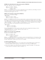
Table 4.1.1 (c) I/O memory map (FF48H–FF71H)
Address
Register
D3
D2
IOC23
D1
IOC22
D0
IOC21
R/W
PUL22
PUL21
R/W
P22
1
Output
0
Input
IOC22
0
Output
Input
IOC21
IOC20
PUL23
0
0
1
Output
Output
On
Input
Input
Off
PUL22
1
On
Off
PUL21
PUL20
P23
1
1
– ∗2
On
On
High
Off
Off
Low
P22
– ∗2
High
Low
PUL20
FF49H
P23
Init ∗1
0
IOC20
FF48H
PUL23
Name
IOC23
P21
P20
FF4AH
Low
– ∗2 High
Low
– ∗2 High
LCD drive duty
0
[LDUTY1, 0]
0
1
2, 3
Duty
1/17
1/16
1/8
switch
0
VC1 LCD regulated voltage switch
0
VC2
On
Off
LCD power On/Off
0
0
Enable Disable Expanded LCD driver signal control
1
All Off Normal LCD all OFF control
0
All On Normal LCD all ON control
F100-F177 F000-F077 Display memory area selection (when 1/8 duty is selected)
0
functions as a general-purpose register when 1/16, 1/17 duty is selected
LC3
LCD contrast adjustment
– ∗2
LC2
– ∗2
[LC3–0]
0
–
15
LC1
– ∗2
Contrast
Light
–
Dark
– ∗2
LC0
ENRTM
0
1 sec 0.5 sec Envelope releasing time
ENRST∗3 Reset Reset Invalid Envelope reset (writing)
ENON
Envelope On/Off
0
On
Off
BZE
0
Enable Disable Buzzer output enable
– ∗2
0 ∗3
Unused
BZSTP∗3
0
Stop
Invalid 1-shot buzzer stop (writing)
BZSHT
0
Trigger Invalid 1-shot buzzer trigger (writing)
Busy Ready 1-shot buzzer status (reading)
SHTPW
0
125 msec 31.25 msec 1-shot buzzer pulse width setting
0 ∗3
Unused
– ∗2
[BZFQ2, 1, 0]
0
1
2
3
BZFQ2
0
Buzzer
Frequency (Hz) 4096.0 3276.8 2730.7 2340.6
BZFQ1
0
frequency
[BZFQ2, 1, 0]
4
5
6
7
Frequency (Hz) 2048.0 1638.4 1365.3 1170.3
BZFQ0
0
selection
0 ∗3
Unused
– ∗2
BDTY2
0
Buzzer signal duty ratio selection
BDTY1
0
(refer to main manual)
BDTY0
0
– ∗2
0 ∗3
Unused
0 ∗3
– ∗2
Unused
SCTRG
0
Trigger Invalid Serial I/F clock trigger (writing)
Run
Stop Serial I/F clock status (reading)
ESIF
0
SIF
Serial I/F enable (P1 port function selection)
I/O
SDP
MSB first LSB first Serial I/F data input/output permutation
0
0
1
[SCS1, 0]
SCPS
Serial I/F clock phase selection
0
Slave
PT
Clock
SCS1
Serial I/F
0
2
3
[SCS1, 0]
SCS0
clock mode selection
0
OSC1/2 OSC1
Clock
P21
P20
LDUTY1
LDUTY1 LDUTY0 VCCHG LPWR
LDUTY0
FF60H
VCCHG
R/W
LPWR
EXLCDC
EXLCDC ALOFF ALON LPAGE ALOFF
ALON
FF61H
LPAGE
R/W
R/W
LC3
LC2
LC1
LC0
FF62H
R/W
ENRTM ENRST ENON
BZE
FF6CH
R/W
W
0
R/W
BZSTP BZSHT SHTPW
FF6DH
R
W
R/W
0
BZFQ2 BZFQ1 BZFQ0
R
R/W
0
BDTY2 BDTY1 BDTY0
R
R/W
FF6EH
FF6FH
0
0
SCTRG
ESIF
FF70H
R
SDP
R/W
SCPS
SCS1
FF71H
R/W
16
SCS0
Comment
P23 I/O control register (EXLCDC=0)
functions as a general-purpose register when FR output is selected
P22 I/O control register (EXLCDC=0)
functions as a general-purpose register when CL output is selected
P21 I/O control register
P20 I/O control register
P23 pull-up control register (EXLCDC=0)
functions as a general-purpose register when FR output is selected
P22 pull-up control register (EXLCDC=0)
functions as a general-purpose register when CL output is selected
P21 pull-up control register
P20 pull-up control register
P23 I/O port data (EXLCDC=0)
functions as a general-purpose register when FR output is selected
P22 I/O port data (EXLCDC=0)
functions as a general-purpose register when CL output is selected
P21 I/O port data
P20 I/O port data
EPSON
S1C6P466 TECHNICAL MANUAL
CHAPTER 4: PERIPHERAL CIRCUITS AND OPERATION (Memory Map)
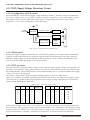
Table 4.1.1 (d) I/O memory map (FF72H–FFC7H)
Address
Register
D3
D2
D1
SD3
SD2
SD1
FF72H
R/W
SD7
SD6
SD5
FF73H
R/W
0
0
TMRST
FF78H
R
W
TM3
TM2
TM1
FF79H
R
TM7
TM6
TM5
FF7AH
R
0
0
SWRST
FF7CH
R
SWD3
W
SWD2
SWD1
FF7DH
R
SWD7
SWD6
SWD5
FF7EH
R
0
EVCNT FCSEL
FFC0H
R
R/W
CHSEL PTOUT CKSEL1
FFC1H
R/W
PTPS01 PTPS00 PTRST0
FFC2H
R/W
W
PTPS11 PTPS10 PTRST1
FFC3H
R/W
RLD03
W
RLD02
RLD01
FFC4H
R/W
RLD07
RLD06
RLD05
FFC5H
R/W
RLD13
RLD12
RLD11
FFC6H
R/W
RLD17
RLD16
RLD15
FFC7H
R/W
S1C6P466 TECHNICAL MANUAL
1
Name Init ∗1
SD3
– ∗2 High
SD0
– ∗2 High
SD2
– ∗2 High
SD1
– ∗2 High
SD0
SD7
– ∗2 High
SD4
– ∗2 High
SD6
– ∗2 High
SD5
– ∗2 High
SD4
– ∗2
0 ∗3
TMRUN
0 ∗3
– ∗2
TMRST∗3 Reset Reset
R/W
TMRUN
0
Run
TM3
0
TM0
TM2
0
TM1
0
TM0
0
TM7
0
TM4
TM6
0
TM5
0
TM4
0
– ∗2
0 ∗3
SWRUN
0 ∗3
– ∗2
SWRST∗3 Reset Reset
R/W
SWRUN
0
Run
SWD3
0
SWD0
SWD2
0
SWD1
0
SWD0
0
SWD7
0
SWD4
SWD6
0
SWD5
0
SWD4
0
0 ∗3
– ∗2
PLPOL
EVCNT
0
Event ct.
FCSEL
0
With NR
PLPOL
0
CHSEL
0
Timer1
CKSEL0
PTOUT
0
On
CKSEL1
0
OSC3
CKSEL0
0
OSC3
0
PTPS01
PTRUN0
0
PTPS00
PTRST0∗3
– ∗2 Reset
R/W
PTRUN0
0
Run
0
PTPS11
PTRUN1
0
PTPS10
PTRST1∗3
– ∗2 Reset
R/W
PTRUN1
0
Run
RLD03
0
RLD00
RLD02
0
RLD01
0
RLD00
0
RLD07
0
RLD04
RLD06
0
RLD05
0
RLD04
0
RLD13
0
RLD10
RLD12
0
RLD11
0
RLD10
0
RLD17
0
RLD14
RLD16
0
RLD15
0
RLD14
0
D0
0
Low
Low
Low
Low
Low
Low
Low
Low
Comment
MSB
Serial I/F transmit/receive data (low-order 4 bits)
LSB
MSB
Serial I/F transmit/receive data (high-order 4 bits)
LSB
Unused
Unused
Invalid Clock timer reset (writing)
Stop Clock timer Run/Stop
Clock timer data (16 Hz)
Clock timer data (32 Hz)
Clock timer data (64 Hz)
Clock timer data (128 Hz)
Clock timer data (1 Hz)
Clock timer data (2 Hz)
Clock timer data (4 Hz)
Clock timer data (8 Hz)
Unused
Unused
Invalid Stopwatch timer reset (writing)
Stop Stopwatch timer Run/Stop
Stopwatch timer data
BCD (1/100 sec)
Stopwatch timer data
BCD (1/10 sec)
Unused
Timer Timer 0 counter mode selection
No NR Timer 0 function selection (for event counter mode)
Timer 0 pulse polarity selection (for event counter mode)
Timer0 TOUT output channel selection
TOUT output control
Off
OSC1 Prescaler 1 source clock selection
OSC1 Prescaler 0 source clock selection
Prescaler 0
[PTPS01, 00]
0
1
2
3
division ratio
Division ratio 1/1
1/4 1/32 1/256
selection
Invalid Timer 0 reset (reload)
Stop Timer 0 Run/Stop
Prescaler 1
[PTPS11, 10]
division ratio
Division ratio
selection
0
1/1
1
1/4
2
3
1/32 1/256
Invalid Timer 1 reset (reload)
Stop Timer 1 Run/Stop
MSB
EPSON
Programmable timer 0 reload data (low-order 4 bits)
LSB
MSB
Programmable timer 0 reload data (high-order 4 bits)
LSB
MSB
Programmable timer 1 reload data (low-order 4 bits)
LSB
MSB
Programmable timer 1 reload data (high-order 4 bits)
LSB
17
CHAPTER 4: PERIPHERAL CIRCUITS AND OPERATION (Memory Map)
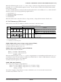
Table 4.1.1 (e) I/O memory map (FFC8H–FFF7H)
Address
Register
D3
D2
D1
D0
PTD03
PTD02
PTD01
PTD00
FFC8H
R
PTD07
PTD06
PTD05
PTD04
FFC9H
R
PTD13
PTD12
PTD11
PTD10
FFCAH
R
PTD17
PTD16
PTD15
PTD14
FFCBH
R
0
0
EIPT1
EIPT0
FFE2H
R
0
R/W
0
0
EISIF
FFE3H
R
0
R/W
0
0
EIK0
FFE4H
R
0
R/W
0
0
EIK1
FFE5H
R
EIT3
R/W
EIT2
EIT1
EIT0
FFE6H
R/W
0
0
EISW1 EISW10
FFE7H
R
0
R/W
0
IPT1
IPT0
FFF2H
R
0
R/W
0
0
ISIF
FFF3H
R
0
R/W
0
0
IK0
FFF4H
R
0
R/W
0
0
IK1
FFF5H
R
IT3
R/W
IT2
IT1
IT0
ISW1
ISW10
FFF6H
R/W
0
0
FFF7H
R
18
R/W
Name Init ∗1
PTD03
0
PTD02
0
PTD01
0
PTD00
0
PTD07
0
PTD06
0
PTD05
0
PTD04
0
PTD13
0
PTD12
0
PTD11
0
PTD10
0
PTD17
0
PTD16
0
PTD15
0
PTD14
0
0 ∗3
– ∗2
0 ∗3
– ∗2
EIPT1
0
EIPT0
0
0 ∗3
– ∗2
0 ∗3
– ∗2
0 ∗3
– ∗2
EISIF
0
0 ∗3
– ∗2
0 ∗3
– ∗2
0 ∗3
– ∗2
EIK0
0
0 ∗3
– ∗2
0 ∗3
– ∗2
0 ∗3
– ∗2
EIK1
0
EIT3
0
EIT2
0
EIT1
0
EIT0
0
0 ∗3
– ∗2
0 ∗3
– ∗2
EISW1
0
EISW10
0
0 ∗3
– ∗2
0 ∗3
– ∗2
IPT1
0
IPT0
0
0 ∗3
– ∗2
0 ∗3
– ∗2
0 ∗3
– ∗2
ISIF
0
0 ∗3
– ∗2
0 ∗3
– ∗2
0 ∗3
– ∗2
IK0
0
0 ∗3
– ∗2
0 ∗3
– ∗2
0 ∗3
– ∗2
IK1
0
IT3
0
IT2
0
IT1
0
IT0
0
0 ∗3
– ∗2
0 ∗3
– ∗2
ISW1
0
ISW10
0
1
Comment
0
MSB
Programmable timer 0 data (low-order 4 bits)
LSB
MSB
Programmable timer 0 data (high-order 4 bits)
LSB
MSB
Programmable timer 1 data (low-order 4 bits)
LSB
MSB
Programmable timer 1 data (high-order 4 bits)
Enable
Enable
Mask
Mask
Enable
Mask
Enable
Mask
Enable
Enable
Enable
Enable
Enable
Mask
Mask
Mask
Mask
Mask
Enable
Enable
(R)
Yes
(W)
Reset
(R)
Yes
(W)
Reset
(R)
Yes
(W)
Reset
(R)
Yes
(W)
Reset
(R)
Yes
(W)
Reset
(R)
Yes
(W)
Reset
Mask
Mask
(R)
No
(W)
Invalid
(R)
No
(W)
Invalid
(R)
No
(W)
Invalid
(R)
No
(W)
Invalid
(R)
No
(W)
Invalid
(R)
No
(W)
Invalid
EPSON
LSB
Unused
Unused
Interrupt mask register (Programmable timer 1)
Interrupt mask register (Programmable timer 0)
Unused
Unused
Unused
Interrupt mask register (Serial I/F)
Unused
Unused
Unused
Interrupt mask register (K00–K03)
Unused
Unused
Unused
Interrupt mask register (K10–K13)
Interrupt mask register (Clock timer 1 Hz)
Interrupt mask register (Clock timer 2 Hz)
Interrupt mask register (Clock timer 8 Hz)
Interrupt mask register (Clock timer 32 Hz)
Unused
Unused
Interrupt mask register (Stopwatch timer 1 Hz)
Interrupt mask register (Stopwatch timer 10 Hz)
Unused
Unused
Interrupt factor flag (Programmable timer 1)
Interrupt factor flag (Programmable timer 0)
Unused
Unused
Unused
Interrupt factor flag (Serial I/F)
Unused
Unused
Unused
Interrupt factor flag (K00–K03)
Unused
Unused
Unused
Interrupt factor flag (K10–K13)
Interrupt factor flag (Clock timer 1 Hz)
Interrupt factor flag (Clock timer 2 Hz)
Interrupt factor flag (Clock timer 8 Hz)
Interrupt factor flag (Clock timer 32 Hz)
Unused
Unused
Interrupt factor flag (Stopwatch timer 1 Hz)
Interrupt factor flag (Stopwatch timer 10 Hz)
S1C6P466 TECHNICAL MANUAL
CHAPTER 4: PERIPHERAL CIRCUITS AND OPERATION (Watchdog Timer)
4.2 Watchdog Timer
4.2.1 Configuration of watchdog timer
The S1C6P466 has a built-in watchdog timer that operates with a 256 Hz divided clock from the OSC1 as
the source clock. The watchdog timer starts operating after initial reset, however, it can be stopped by the
software. The watchdog timer must be reset cyclically by the software while it operates. If the watchdog
timer is not reset in at least 3–4 seconds, it generates a non-maskable interrupt (NMI) to the CPU.
Figure 4.2.1.1 is the block diagram of the watchdog timer.
Watchdog timer
OSC1 dividing signal 256 Hz
Non-maskable
interrupt (NMI)
Watchdog timer enable signal
Watchdog timer reset signal
Fig. 4.2.1.1 Watchdog timer block diagram
The watchdog timer contains a 10-bit binary counter, and generates the non-maskable interrupt when the
last stage of the counter (0.25 Hz) overflows.
Watchdog timer reset processing in the program's main routine enables detection of program overrun,
such as when the main routine's watchdog timer processing is bypassed. Ordinarily this routine is
incorporated where periodic processing takes place, just as for the timer interrupt routine.
The watchdog timer operates in the HALT mode. If a HALT status continues for 3–4 seconds, the nonmaskable interrupt releases the HALT status.
4.2.2 Interrupt function
If the watchdog timer is not reset periodically, the non-maskable interrupt (NMI) is generated to the core
CPU. Since this interrupt cannot be masked, it is accepted even in the interrupt disable status (I flag =
"0"). However, it is not accepted when the CPU is in the interrupt mask state until SP1 and SP2 are set as a
pair, such as after initial reset or during re-setting the stack pointer. The interrupt vector of NMI is
assigned to 0100H in the program memory.
S1C6P466 TECHNICAL MANUAL
EPSON
19
CHAPTER 4: PERIPHERAL CIRCUITS AND OPERATION (Watchdog Timer)
4.2.3 I/O memory of watchdog timer
Table 4.2.3.1 shows the I/O address and control bits for the watchdog timer.
Table 4.2.3.1 Control bits of watchdog timer
Address
Register
D3
D2
0
0
FF07H
R
Comment
1
0
Name Init ∗1
0 ∗3
– ∗2
Unused
WDEN WDRST
0 ∗3
– ∗2
Unused
WDEN
1
Enable Disable Watchdog timer enable
R/W
W
WDRST∗3 Reset Reset Invalid Watchdog timer reset (writing)
D1
D0
*1 Initial value at initial reset
*2 Not set in the circuit
*3 Constantly "0" when being read
WDEN: Watchdog timer enable register (FF07H•D1)
Selects whether the watchdog timer is used (enabled) or not (disabled).
When "1" is written: Enabled
When "0" is written: Disabled
Reading: Valid
When "1" is written to the WDEN register, the watchdog timer starts count operation. When "0" is written,
the watchdog timer does not count and does not generate the interrupt (NMI).
At initial reset, this register is set to "1".
WDRST: Watchdog timer reset (FF07H•D0)
Resets the watchdog timer.
When "1" is written: Watchdog timer is reset
When "0" is written: No operation
Reading: Always "0"
When "1" is written to WDRST, the watchdog timer is reset and restarts immediately after that. When "0"
is written, no operation results.
This bit is dedicated for writing, and is always "0" for reading.
4.2.4 Programming notes
(1) When the watchdog timer is being used, the software must reset it within 3-second cycles.
(2) Because the watchdog timer is set in operation state by initial reset, set the watchdog timer to disabled
state (not used) before generating an interrupt (NMI) if it is not used.
20
EPSON
S1C6P466 TECHNICAL MANUAL
CHAPTER 4: PERIPHERAL CIRCUITS AND OPERATION (Oscillation Circuit)
4.3 Oscillation Circuit
4.3.1 Configuration of oscillation circuit
The S1C6P466 has two oscillation circuits (OSC1 and OSC3). OSC1 is a crystal oscillation circuit that
supplies the operating clock to the CPU and peripheral circuits. OSC3 is a ceramic oscillation circuit.
When processing with the S1C6P466 requires high-speed operation, the CPU operating clock can be
switched from OSC1 to OSC3 by software. Figure 4.3.1.1 is the block diagram of this oscillation system.
OSC1
oscillation circuit
Divider
To peripheral circuits
Clock
switch
OSC3
oscillation circuit
To CPU
CPU clock selection signal
Oscillation circuit control signal
Fig. 4.3.1.1 Oscillation system block diagram
4.3.2 OSC1 oscillation circuit
The OSC1 oscillation circuit generates the main clock for the CPU and the peripheral circuits. The oscillator type is a crystal oscillation circuit and the oscillation frequency is 32.768 kHz (Typ.).
Figure 4.3.2.1 is the block diagram of the OSC1 oscillation circuit.
CGX
RDX
To CPU
(and peripheral circuits)
RFX
X'tal
OSC1
C DX
OSC2
V SS
V SS
Fig. 4.3.2.1 OSC1 oscillation circuit
As shown in Figure 4.3.2.1, the crystal oscillation circuit can be configured simply by connecting the
crystal oscillator (X'tal) of 32.768 kHz (Typ.) between the OSC1 and OSC2 terminals and the trimmer
capacitor (CGX) between the OSC1 and VSS terminals
4.3.3 OSC3 oscillation circuit
The S1C6P466 has built-in the OSC3 oscillation circuit that generates the CPU's sub-clock (Max. 4 MHz)
for high speed operation and the source clock for peripheral circuits needing a high speed clock (programmable timer, FOUT output). The oscillator type is a ceramic oscillation circuit and a ceramic oscillator and two capacitors (gate and drain capacitance) are required.
Figure 4.3.3.1 is the block diagram of the OSC3 oscillation circuit.
C GC
To CPU
(and some peripheral circuits)
RFC
Ceramic
CDC
OSC3
OSC4
RDC
Oscillation circuit control signal
VSS
Fig. 4.3.3.1 OSC3 oscillation circuit
S1C6P466 TECHNICAL MANUAL
EPSON
21
CHAPTER 4: PERIPHERAL CIRCUITS AND OPERATION (Oscillation Circuit)
As shown in Figure 4.3.3.1, the ceramic oscillation circuit can be configured by connecting the ceramic
oscillator (Max. 4 MHz) between the OSC3 and OSC4 terminals, capacitor CGC between the OSC3 and
OSC4 terminals, and capacitor CDC between the OSC4 and VSS terminals. For both CGC and CDC, connect
capacitors that are about 30 pF. To reduce current consumption of the OSC3 oscillation circuit, oscillation
can be stopped by the software (OSCC register).
When the OSC3 oscillation circuit is not used, leave the OSC3 and OSC4 terminals open.
4.3.4 Operating voltage
The S1C6P466 generates the VD1 voltage internally for the OSC1 oscillation circuit in order to stabilize
oscillation. In the S1C6P466, the VD1 voltage is used only for the OSC1 oscillation circuit and the voltage
level is fixed at 1.85±0.3 V.
Therefore, setting of the VDC register (FF00H•D0) required in the mask ROM model is invalidated and
does not affect the VD1 voltage level. However, note that the VDC register value affects the CPU clock
switch control.
When using the S1C6P466 as a development tool for the S1C63454/63458/63466, switch the operating
voltage using the VDC register according to the control sequence of the model (refer to the "Technical
Manual").
Furthermore, internal logic circuits of the S1C6P466 except for the OSC1 oscillation circuit operate with
the source voltage supplied between the VDD and VSS terminal.
4.3.5 Switching operating clock
The CPU system clock is switched to OSC1 or OSC3 by software (CLKCHG register).
When using OSC3 as the CPU system clock, first turn the OSC3 oscillation ON and then switch the clock
after waiting 5 msec or more for oscillation stabilization.
When switching from OSC3 to OSC1, turn the OSC3 oscillation circuit OFF after switching the clock.
OSC1 → OSC3
1. Set OSCC to "1" (OSC3 oscillation ON).
2. Maintain 5 msec or more.
3. Set CLKCHG to "1" (OSC1 → OSC3).
OSC3 → OSC1
1. Set CLKCHG to "0" (OSC3 → OSC1).
2. Set OSCC to "0" (OSC3 oscillation OFF).
4.3.6 Clock frequency and instruction execution time
Table 4.3.6.1 shows the instruction execution time according to each frequency of the system clock.
Table 4.3.6.1 Clock frequency and instruction execution time
Clock frequency
OSC1: 32.768 kHz
OSC3: 4 MHz
22
Instruction execution time (µsec)
1-cycle instruction 2-cycle instruction 3-cycle instruction
61
122
183
0.5
1
1.5
EPSON
S1C6P466 TECHNICAL MANUAL
CHAPTER 4: PERIPHERAL CIRCUITS AND OPERATION (Oscillation Circuit)
4.3.7 I/O memory of oscillation circuit
Table 4.3.7.1 shows the I/O address and the control bits for the oscillation circuit.
Table 4.3.7.1 Control bits of oscillation circuit
Address
Register
D3
D2
D1
D0
CLKCHG OSCC
0
VDC
R/W
R
R/W
FF00H
Name Init ∗1
CLKCHG
0
OSCC
0
0 ∗3
– ∗2
VDC
0
1
OSC3
On
1
Comment
0
OSC1 CPU clock switch
OSC3 oscillation On/Off
Off
Unused
0
CPU operating voltage switch
*1 Initial value at initial reset
*2 Not set in the circuit
*3 Constantly "0" when being read
VDC: CPU operating voltage switching register (FF00H•D0)
In the S1C6P466, the value set in this register does not affect the VD1 voltage level. However, note that the
register value affects the CLKCHG register that switches the CPU clock.
When using the S1C6P466 as a development tool for the S1C63454/63458/63466, switch the operating
voltage using this register according to the control sequence of the model (refer to the "Technical
Manual").
At initial reset, this register is set to "0".
OSCC: OSC3 oscillation control register (FF00H•D2)
Controls oscillation ON/OFF for the OSC3 oscillation circuit.
When "1" is written: OSC3 oscillation ON
When "0" is written: OSC3 oscillation OFF
Reading: Valid
When it is necessary to operate the CPU at high speed, set OSCC to "1". At other times, set it to "0" to
reduce current consumption.
At initial reset, this register is set to "0".
CLKCHG: CPU system clock switching register (FF00H•D3)
The CPU's operation clock is selected with this register.
When "1" is written: OSC3 clock is selected
When "0" is written: OSC1 clock is selected
Reading: Valid
When the CPU clock is to be OSC3, set CLKCHG to "1"; for OSC1, set CLKCHG to "0".
After turning the OSC3 oscillation ON (OSCC = "1"), switching of the clock should be done after waiting
5 msec or more.
When VDC is set to "0" and when OSC3 oscillation is OFF (OSCC = "0"), setting of CLKCHG = "1"
becomes invalid and switching to OSC3 is not performed.
At initial reset, this register is set to "0".
S1C6P466 TECHNICAL MANUAL
EPSON
23
CHAPTER 4: PERIPHERAL CIRCUITS AND OPERATION (Oscillation Circuit)
4.3.8 Programming notes
(1) It takes at least 5 msec from the time the OSC3 oscillation circuit goes ON until the oscillation stabilizes. Consequently, when switching the CPU operation clock from OSC1 to OSC3, do this after a
minimum of 5 msec have elapsed since the OSC3 oscillation went ON.
Further, the oscillation stabilization time varies depending on the external oscillator characteristics
and conditions of use, so allow ample margin when setting the wait time.
(2) When switching the clock form OSC3 to OSC1, use a separate instruction for switching the OSC3
oscillation OFF. An error in the CPU operation can result if this processing is performed at the same
time by the one instruction.
(3) In the S1C6P466, the VDC register value does not affect the VD1 voltage level. However, note that the
CPU clock cannot be switched from OSC1 to OSC3 using the CLKCHG register if the VDC register
value is "0".
When using the S1C6P466 as a development tool for the S1C63454/63458/63466, switch the operating
voltage using the VDC register according to the control sequence of the model (refer to the "Technical
Manual").
24
EPSON
S1C6P466 TECHNICAL MANUAL
CHAPTER 4: PERIPHERAL CIRCUITS AND OPERATION (Input Ports)
4.4 Input Ports (K00–K03 and K10–K13)
4.4.1 Configuration of input ports
The S1C6P466 has eight bits of general-purpose input ports. Each of the input port terminals (K00–K03,
K10–K13) provides a pull-up resistor.
Figure 4.4.1.1 shows the configuration of the input port.
Interrupt
request
Kxx
Data bus
VDD
Address
VSS
Fig. 4.4.1.1 Configuration of input port
4.4.2 Interrupt function
All eight bits of the input ports (K00–K03, K10–K13) provide the interrupt function. The conditions for
issuing an interrupt can be set by the software. Further, whether to mask the interrupt function can be
selected by the software.
Figure 4.4.2.1 shows the configuration of K00–K03 (K10–K13) interrupt circuit.
K00, 10
Address
Address
Data bus
Input comparison
register (KCP00, 10)
Interrupt factor
flag (IK0, 1)
Interrupt
request
Address
Interrupt selection
register (SIK00, 10)
Interrupt mask
register (EIK0, 1)
Address
Address
K01, 11
K02, 12
K03, 13
Fig. 4.4.2.1 Input interrupt circuit configuration
S1C6P466 TECHNICAL MANUAL
EPSON
25
CHAPTER 4: PERIPHERAL CIRCUITS AND OPERATION (Input Ports)
The interrupt selection register (SIK) and input comparison register (KCP) are individually set for the
input ports K00–K03 and K10–K13, and can specify the terminals for generating interrupt and interrupt
timing.
The interrupt selection registers (SIK00–SIK03, SIK10–SIK13) select what input of K00–K03 and K10–K13
to use for the interrupt. Writing "1" into an interrupt selection register incorporates that input port into
the interrupt generation conditions. The changing the input port where the interrupt selection register
has been set to "0" does not affect the generation of the interrupt.
The input interrupt timing can select that the interrupt be generated at the rising edge of the input or that
it be generated at the falling edge according to the set value of the input comparison registers (KCP00–
KCP03, KCP10–KCP13).
By setting these two conditions, the interrupt for K00–K03 or K10–K13 is generated when input ports in
which an interrupt has been enabled by the input selection registers and the contents of the input comparison registers have been changed from matching to no matching.
The interrupt mask registers (EIK0, EIK1) enable the interrupt mask to be selected for K00–K03 and K10–
K13.
When the interrupt is generated, the interrupt factor flag (IK0, IK1) is set to "1".
Figure 4.4.2.2 shows an example of an interrupt for K00–K03.
Interrupt selection register
SIK03
1
SIK02
1
SIK01
1
SIK00
0
Input comparison register
KCP03 KCP02 KCP01 KCP00
1
0
1
0
With the above setting, the interrupt of K00–K03 is generated under the following condition:
Input port
(1)
K03
1
K02
0
K01
1
K00
0
(2)
K03
1
K02
0
K01
1
K00
1
(3)
K03
0
K02
0
K01
1
K00
1
K03
K02
K01
K00
0
1
1
1
(4)
(Initial value)
Interrupt generation
Because K00 interrupt is set to disable, interrupt will be
generated when no matching occurs between the
contents of the 3 bits K01–K03 and the 3 bits input
comparison register KCP01–KCP03.
Fig. 4.4.2.2 Example of interrupt of K00–K03
K00 interrupt is disabled by the interrupt selection register (SIK00), so that an interrupt does not occur at
(2). At (3), K03 changes to "0"; the data of the terminals that are interrupt enabled no longer match the
data of the input comparison registers, so that interrupt occurs. As already explained, the condition for
the interrupt to occur is the change in the port data and contents of the input comparison registers from
matching to no matching. Hence, in (4), when the no matching status changes to another no matching
status, an interrupt does not occur. Further, terminals that have been masked for interrupt do not affect
the conditions for interrupt generation.
4.4.3 Mask option
In the S1C6P466, the input port specification is fixed at "Input with pull-up resistor".
26
EPSON
S1C6P466 TECHNICAL MANUAL
CHAPTER 4: PERIPHERAL CIRCUITS AND OPERATION (Input Ports)
4.4.4 I/O memory of input ports
Table 4.4.4.1 shows the I/O addresses and the control bits for the input ports.
Table 4.4.4.1 Control bits of input ports
Address
FF20H
FF21H
FF22H
FF24H
FF25H
FF26H
FFE4H
FFE5H
FFF4H
FFF5H
Register
D3
D2
D1
D0
Name
SIK03
SIK03 SIK02 SIK01 SIK00
SIK02
SIK01
R/W
SIK00
K03
K03
K02
K01
K00
K02
K01
R
K00
KCP03
KCP03 KCP02 KCP01 KCP00
KCP02
KCP01
R/W
KCP00
SIK13
SIK13 SIK12 SIK11 SIK10
SIK12
SIK11
R/W
SIK10
K13
K13
K12
K11
K10
K12
K11
R
K10
KCP13
KCP13 KCP12 KCP11 KCP10
KCP12
KCP11
R/W
KCP10
0 ∗3
0
0
0
EIK0
0 ∗3
0 ∗3
R
R/W
EIK0
0 ∗3
0
0
0
EIK1
0 ∗3
0 ∗3
R
R/W
EIK1
0 ∗3
0
0
0
IK0
0 ∗3
0 ∗3
R
R/W
IK0
0 ∗3
0
0
0
IK1
0 ∗3
0 ∗3
R
R/W
IK1
Init ∗1
0
0
0
0
– ∗2
– ∗2
– ∗2
– ∗2
1
1
1
1
0
0
0
0
– ∗2
– ∗2
– ∗2
– ∗2
1
1
1
1
– ∗2
– ∗2
– ∗2
0
– ∗2
– ∗2
– ∗2
0
– ∗2
– ∗2
– ∗2
0
– ∗2
– ∗2
– ∗2
0
1
Enable
Enable
Enable
Enable
High
High
High
High
0
Disable
Disable
Disable
Disable
Low
Low
Low
Low
Comment
K00–K03 interrupt selection register
K00–K03 input port data
K00–K03 input comparison register
Enable
Enable
Enable
Enable
High
High
High
High
Disable
Disable
Disable
Disable
Low
Low
Low
Low
K10–K13 interrupt selection register
K10–K13 input port data
K10–K13 input comparison register
Enable
Enable
(R)
Yes
(W)
Reset
(R)
Yes
(W)
Reset
Unused
Unused
Unused
Mask Interrupt mask register (K00–K03)
Unused
Unused
Unused
Mask Interrupt mask register (K10–K13)
Unused
(R)
Unused
No
(W) Unused
Invalid Interrupt factor flag (K00–K03)
Unused
(R)
Unused
No
(W) Unused
Invalid Interrupt factor flag (K10–K13)
*1 Initial value at initial reset
*2 Not set in the circuit
*3 Constantly "0" when being read
K00–K03: K0 port input port data (FF21H)
K10–K13: K1 port input port data (FF25H)
Input data of the input port terminals can be read with these registers.
When "1" is read: High level
When "0" is read: Low level
Writing: Invalid
The reading is "1" when the terminal voltage of the eight bits of the input ports (K00–K03, K10–K13) goes
high (VDD), and "0" when the voltage goes low (VSS).
These bits are dedicated for reading, so writing cannot be done.
S1C6P466 TECHNICAL MANUAL
EPSON
27
CHAPTER 4: PERIPHERAL CIRCUITS AND OPERATION (Input Ports)
SIK00–SIK03: K0 port interrupt selection register (FF20H)
SIK10–SIK13: K1 port interrupt selection register (FF24H)
Selects the ports to be used for the K00–K03 and K10–K13 input interrupts.
When "1" is written: Enable
When "0" is written: Disable
Reading: Valid
Enables the interrupt for the input ports (K00–K03, K10–K13) for which "1" has been written into the
interrupt selection registers (SIK00–SIK03, SIK10–SIK13). The input port set for "0" does not affect the
interrupt generation condition.
At initial reset, these registers are set to "0".
KCP00–KCP03: K0 port input comparison register (FF22H)
KCP10–KCP13: K1 port input comparison register (FF26H)
Interrupt conditions for terminals K00–K03 and K10–K13 can be set with these registers.
When "1" is written: Falling edge
When "0" is written: Rising edge
Reading: Valid
The interrupt conditions can be set for the rising or falling edge of input for each of the eight bits (K00–
K03 and K10–K13), through the input comparison registers (KCP00–KCP03 and KCP10–KCP13).
For KCP00–KCP03, a comparison is done only with the ports that are enabled by the interrupt among
K00–K03 by means of the SIK00–SIK03 registers. For KCP10–KCP13, a comparison is done only with the
ports that are enabled by the interrupt among K10–K13 by means of the SIK10–SIK13 registers.
At initial reset, these registers are set to "1".
EIK0: K0 input interrupt mask register (FFE4H•D0)
EIK1: K1 input interrupt mask register (FFE5H•D0)
Masking the interrupt of the input port can be selected with these registers.
When "1" is written: Enable
When "0" is written: Mask
Reading: Valid
With these registers, masking of the input port interrupt can be selected for each of the two systems (K00–
K03, K10–K13).
At initial reset, these registers are set to "0".
IK0: K0 input interrupt factor flag (FFF4H•D0)
IK1: K1 input interrupt factor flag (FFF5H•D0)
These flags indicate the occurrence of input interrupt.
When "1" is read: Interrupt has occurred
When "0" is read: Interrupt has not occurred
When "1" is written: Flag is reset
When "0" is written: Invalid
The interrupt factor flags IK0 and IK1 are associated with K00–K03 and K10–K13, respectively. From the
status of these flags, the software can decide whether an input interrupt has occurred.
The interrupt factor flag is set to "1" when the interrupt condition is established regardless of the interrupt
mask register setting. However, the interrupt does not occur to the CPU when the interrupt is masked.
These flags are reset to "0" by writing "1" to them.
After an interrupt occurs, the same interrupt will occur again if the interrupt enabled state (I flag = "1") is
set or the RETI instruction is executed unless the interrupt factor flag is reset. Therefore, be sure to reset
(write "1" to) the interrupt factor flag in the interrupt service routine before shifting to the interrupt
enabled state.
At initial reset, these flags are set to "0".
28
EPSON
S1C6P466 TECHNICAL MANUAL
CHAPTER 4: PERIPHERAL CIRCUITS AND OPERATION (Input Ports)
4.4.5 Programming notes
(1) When input ports are changed from low to high by pull-up resistors, the rise of the waveform is
delayed on account of the time constant of the pull-up resistor and input gate capacitance. Hence,
when fetching input ports, set an appropriate waiting time.
Particular care needs to be taken of the key scan during key matrix configuration.
Make this waiting time the amount of time or more calculated by the following expression.
10 × C × R
C: terminal capacitance 5 pF + parasitic capacitance ? pF
R: pull-up resistance 330 kΩ
(2) The K13 terminal functions as the clock input terminal for the programmable timer, and the input
signal is shared with the input port and the programmable timer. Therefore, when the K13 terminal is
set to the clock input terminal for the programmable timer, take care of the interrupt setting.
(3) After an interrupt occurs, the same interrupt will occur again if the interrupt enabled state (I flag =
"1") is set or the RETI instruction is executed unless the interrupt factor flag is reset. Therefore, be sure
to reset (write "1" to) the interrupt factor flag in the interrupt service routine before shifting to the
interrupt enabled state.
S1C6P466 TECHNICAL MANUAL
EPSON
29
CHAPTER 4: PERIPHERAL CIRCUITS AND OPERATION (Output Ports)
4.5 Output Ports (R00–R03, R10–R13 and R20–R23)
4.5.1 Configuration of output ports
The S1C6P466 has 12 bits of general output ports.
The output specification of each output port is fixed at complementary output.
Figure 4.5.1.1 shows the configuration of the output port.
Data bus
Address
VDD
High impedance
control register
Data register
Rxx
Address
VSS
Fig. 4.5.1.1 Configuration of output port
The R02 and R03 output terminals are shared with special output terminals (TOUT, FOUT), and this
function is selected by the software. At initial reset, these are all set to the general purpose output port.
Table 4.5.1.1 shows the setting of the output terminals by function selection.
Table 4.5.1.1 Function setting of output terminals
Terminal
name
R00
R01
Terminal status
at initial reset
R00 (High output)
R01 (High output)
Special output
TOUT
FOUT
R00 R00
R01 R01
R02
R02 (High output)
TOUT
R03
R03 (High output)
FOUT
R10–R13 R10–R13 (High output) R10–R13 R10–R13
R20–R23 R20–R23 (High output) R20–R23 R20–R23
When using the output port (R02, R03) as the special output port, the data register must be fixed at "1"
and the high impedance control register must be fixd at "0" (data output).
4.5.2 Mask option
In the S1C6P466, output specifications of all the output ports are fixed at complementary output.
30
EPSON
S1C6P466 TECHNICAL MANUAL
CHAPTER 4: PERIPHERAL CIRCUITS AND OPERATION (Output Ports)
4.5.3 High impedance control
The terminal output status of the output ports can be set to a high impedance status. This control is done
using the high impedance control registers.
The high impedance control registers are provided to correspond with the output ports as shown below.
High impedance control register
R00HIZ
R01HIZ
R02HIZ
R03HIZ
R1HIZ
R2HIZ
Corresponding output port
R00 (1-bit)
R01 (1-bit)
R02 (1-bit)
R03 (1-bit)
R10–R13 (4-bit)
R20–R23 (4-bit)
When "1" is written to the high impedance control register, the corresponding output port terminal goes
into high impedance status. When "0" is written, the port outputs a signal according to the data register.
4.5.4 Special output
In addition to the regular DC output, special output can be selected for the output ports R02 and R03 as
shown in Table 4.5.4.1 with the software.
Figure 4.5.4.1 shows the configuration of the R02 and R03 output ports.
Table 4.5.4.1 Special output
Terminal
R03
Special output
FOUT
Output control register
FOUTE
R02
TOUT
PTOUT
FOUT
Register
FOUTE
R03
(FOUT)
Data bus
Register
R03
Register
R03HIZ
TOUT
Register
PTOUT
R02
(TOUT)
Register
R02
Register
R02HIZ
Fig. 4.5.4.1 Configuration of R02 and R03 output ports
At initial reset, the output port data register is set to "1" and the high impedance control register is set to
"0". Consequently, the output terminal goes high (VDD).
When using the output port (R02, R03) as the special output port, fix the data register (R02, R03) at "1"
and the high impedance control register (R02HIZ, R03HIZ) at "0" (data output). The respective signal
should be turned ON and OFF using the special output control register.
Notes: • Be aware that the output terminal is fixed at a low (VSS) level the same as the DC output if "0" is
written to the R02 and R03 registers when the special output has been selected.
• Be aware that the output terminal shifts into high impedance status when "1" is written to the
high impedance control register (R02HIZ, R03HIZ).
S1C6P466 TECHNICAL MANUAL
EPSON
31
CHAPTER 4: PERIPHERAL CIRCUITS AND OPERATION (Output Ports)
• TOUT (R02)
The R02 terminal can output a TOUT signal.
The TOUT signal is the clock that is output from the programmable timer, and can be used to provide
a clock signal to an external device.
To output the TOUT signal, fix the R02 register at "1" and the R02HIZ register at "0", and turn the
signal ON and OFF using the PTOUT register. It is, however, necessary to control the programmable
timer.
Refer to Section 4.10, "Programmable Timer" for details of the programmable timer.
Note: A hazard may occur when the TOUT signal is turned ON and OFF.
Figure 4.5.4.2 shows the output waveform of the TOUT signal.
R02HIZ register
Fix at "0"
R02 register
Fix at "1"
PTOUT register
"0"
"1"
"0"
TOUT output
Fig. 4.5.4.2 Output waveform of TOUT signal
• FOUT (R03)
The R03 terminal can output a FOUT signal.
The FOUT signal is a clock (fOSC1 or fOSC3) that is output from the oscillation circuit or a clock that the
fOSC1 clock has divided in the internal circuit, and can be used to provide a clock signal to an external
device.
To output the FOUT signal, fix the R03 register at "1" and the R03HIZ register at "0", and turn the
signal ON and OFF using the FOUTE register.
The frequency of the output clock may be selected from among 4 types shown in Table 4.5.4.2 by
setting the FOFQ0 and FOFQ1 registers.
Table 4.5.4.2 FOUT clock frequency
FOFQ1
1
1
FOFQ0
1
0
Clock frequency
fOSC3
fOSC1
0
1
fOSC1 × 1/8
0
0
fOSC1 × 1/64
fOSC1: Clock that is output from the OSC1 oscillation circuit
fOSC3: Clock that is output from the OSC3 oscillation circuit
When fOSC3 is selected for the FOUT signal frequency, it is necessary to control the OSC3 oscillation
circuit before output.
Refer to Section 4.3, "Oscillation Circuit", for the control and notes.
Note: A hazard may occur when the FOUT signal is turned ON and OFF.
Figure 4.5.4.3 shows the output waveform of the FOUT signal.
R03HIZ register
Fix at "0"
R03 register
Fix at "1"
FOUTE register
"0"
"1"
"0"
FOUT output
Fig. 4.5.4.3 Output waveform of FOUT signal
32
EPSON
S1C6P466 TECHNICAL MANUAL
CHAPTER 4: PERIPHERAL CIRCUITS AND OPERATION (Output Ports)
4.5.5 I/O memory of output ports
Table 4.5.5.1 shows the I/O addresses and control bits for the output ports.
Table 4.5.5.1 Control bits of output ports
Address
Register
Comment
Name Init ∗1
1
0
FOUTE
0
Enable Disable FOUT output enable
FOUTE
0
FOFQ1 FOFQ0
0 ∗3
Unused
– ∗2
FF06H
FOUT
FOFQ1
0
1
2
[FOFQ1, 0]
0
3
frequency
R/W
R
R/W
Frequency fOSC1/64 fOSC1/8 fOSC1 fOSC3
FOFQ0
0
selection
R03HIZ
0
High-Z Output R03 output high impedance control (FOUTE=0)
FOUT output high impedance control (FOUTE=1)
R03HIZ R02HIZ R01HIZ R00HIZ
R02HIZ
0
High-Z Output R02 output high impedance control (PTOUT=0)
FF30H
TOUT output high impedance control (PTOUT=1)
R01HIZ
0
High-Z Output R01 output high impedance control
R/W
R00HIZ
0
High-Z Output R00 output high impedance control
R03
1
High
Low R03 output port data (FOUTE=0) Fix at "1" when FOUT is used
R03
R02
R01
R00
R02
1
High
Low R02 output port data (PTOUT=0) Fix at "1" when TOUT is used
FF31H
R01
1
High
Low R01 output port data
R/W
R00
1
High
Low R00 output port data
0 ∗3
Unused
– ∗2
0
0
0
R1HIZ
0 ∗3
– ∗2
Unused
FF32H
0 ∗3
– ∗2
Unused
R
R/W
R1HIZ
0
High-Z Output R1 output high impedance control
R13
1
High
Low
R13
R12
R11
R10
R12
1
High
Low
R10–R13 output port data
FF33H
R11
1
High
Low
R/W
R10
1
High
Low
0 ∗3
Unused
– ∗2
0
0
0
R2HIZ
0 ∗3
– ∗2
Unused
FF34H
0 ∗3
– ∗2
Unused
R
R/W
R2HIZ
0
High-Z Output R2 output high impedance control
R23
1
High
Low
R23
R22
R21
R20
R22
1
High
Low
R20–R23 output port data
FF35H
R21
1
High
Low
R/W
R20
1
High
Low
CHSEL
0
Timer1 Timer0 TOUT output channel selection
CHSEL PTOUT CKSEL1 CKSEL0
PTOUT
TOUT output control
0
On
Off
FFC1H
CKSEL1
0
OSC3 OSC1 Prescaler 1 source clock selection
R/W
CKSEL0
0
OSC3 OSC1 Prescaler 0 source clock selection
D3
D2
D1
D0
*1 Initial value at initial reset
*2 Not set in the circuit
*3 Constantly "0" when being read
R00HIZ–R03HIZ: R0 port high impedance control register (FF30H)
R1HIZ:
R1 port high impedance control register (FF32H•D0)
R2HIZ:
R2 port high impedance control register (FF34H•D0)
Controls high impedance output of the output port.
When "1" is written: High impedance
When "0" is written: Data output
Reading: Valid
By writing "0" to the high impedance control register, the corresponding output terminal outputs according to the data register. When "1" is written, it shifts into high impedance status.
When the output ports R02 and R03 are used for special output (TOUT, FOUT), fix the R02HIZ register
and the R03HIZ register at "0" (data output).
At initial reset, these registers are set to "0".
S1C6P466 TECHNICAL MANUAL
EPSON
33
CHAPTER 4: PERIPHERAL CIRCUITS AND OPERATION (Output Ports)
R00–R03: R0 output port data register (FF31H)
R10–R13: R1 output port data register (FF33H)
R20–R23: R2 output port data register (FF35H)
Set the output data for the output ports.
When "1" is written: High level output
When "0" is written: Low level output
Reading: Valid
The output port terminals output the data written in the corresponding data registers without changing
it. When "1" is written to the register, the output port terminal goes high (VDD), and when "0" is written,
the output port terminal goes low (VSS).
When the output ports R02 and R03 are used for special output (TOUT, FOUT), fix the R02 register and
the R03 register at "1".
At initial reset, these registers are all set to "1".
FOUTE: FOUT output control register (FF06H•D3)
Controls the FOUT output.
When "1" is written: FOUT output ON
When "0" is written: FOUT output OFF
Reading: Valid
By writing "1" to the FOUTE register when the R03 register has been set to "1" and the R03HIZ register
has been set to "0", an FOUT signal is output from the R03 terminal. When "0" is written, the R03 terminal
goes high (VDD).
When using the R03 output port for DC output, fix this register at "0".
At initial reset, this register is set to "0".
FOFQ0, FOFQ1: FOUT frequency selection register (FF06H•D0, D1)
Selects a frequency of the FOUT signal.
Table 4.5.5.2 FOUT clock frequency
FOFQ1
1
FOFQ0
1
Clock frequency
fOSC3
1
0
0
0
1
0
fOSC1
fOSC1 × 1/8
fOSC1 × 1/64
At initial reset, this register is set to "0".
PTOUT: TOUT output control register (FFC1H•D2)
Controls the TOUT output.
When "1" is written: TOUT output ON
When "0" is written: TOUT output OFF
Reading: Valid
By writing "1" to the PTOUT register when the R02 register has been set to "1" and the R02HIZ register
has been set to "0", the TOUT signal is output from the R02 terminal. When "0" is written, the R02 terminal goes high (VDD).
When using the R02 output port for DC output, fix this register at "0".
At initial reset, this register is set to "0".
34
EPSON
S1C6P466 TECHNICAL MANUAL
CHAPTER 4: PERIPHERAL CIRCUITS AND OPERATION (Output Ports)
4.5.6 Programming notes
(1) When using the output port (R02, R03) as the special output port, fix the data register (R02, R03) at "1"
and the high impedance control register (R02HIZ, R03HIZ) at "0" (data output).
Be aware that the output terminal is fixed at a low (VSS) level the same as the DC output if "0" is
written to the R02 and R03 registers when the special output has been selected.
Be aware that the output terminal shifts into high impedance status when "1" is written to the high
impedance control register (R02HIZ, R03HIZ).
(2) A hazard may occur when the FOUT signal and the TOUT signal are turned ON and OFF.
(3) When fOSC3 is selected for the FOUT signal frequency, it is necessary to control the OSC3 oscillation
circuit before output.
Refer to Section 4.3, "Oscillation Circuit", for the control and notes.
S1C6P466 TECHNICAL MANUAL
EPSON
35
CHAPTER 4: PERIPHERAL CIRCUITS AND OPERATION (I/O Ports)
4.6 I/O Ports (P00–P03, P10–P13 and P20–P23)
4.6.1 Configuration of I/O ports
The S1C6P466 has 12 bits of general-purpose I/O ports.
Figure 4.6.1.1 shows the configuration of the I/O port.
Data bus
Address
VDD
Pull-up control
register (PUL)
Address
Address
Data
register
Address
I/O control
register (IOC)
PXX
Fig. 4.6.1.1 Configuration of I/O port
The I/O port terminals P10 to P13 are shared with the serial interface input/output terminals. The P22
and P23 terminals are shared with the special output (CL, FR) terminals. The software can select the
function to be used. At initial reset, these are all set to the I/O port.
Table 4.6.1.1 shows the setting of the input/output terminals by function selection.
Table 4.6.1.1 Function setting of input/output terminals
Terminal status
Special output
at initial reset
CL
FR
P00–P03 P00–P03 (Input & pull-up) P00–P03 P00–P03
P10
P10 (Input & pull-up)
P11
P11 (Input & pull-up)
P12
P12 (Input & pull-up)
P13
P13 (Input & pull-up)
P20
P20 (Input & pull-up)
P20
P20
P21
P21 (Input & pull-up)
P21
P21
P22
P22 (Input & pull-up)
CL
P23
P23 (Input & pull-up)
FR
Terminal
Serial I/F
Master
Slave
P00–P03 P00–P03
SIN(I)
SIN(I)
SOUT(O) SOUT(O)
SCLK(O) SCLK(I)
P13
SRDY(O)
P20
P21
P20
P21
When these ports are used as I/O ports, the ports can be set to either input mode or output mode individually (in 1-bit unit). Modes can be set by writing data to the I/O control registers.
Refer to Section 4.11, "Serial Interface", for control of the serial interface.
4.6.2 Mask option
In the S1C6P466, the I/O port specification is fixed at "with pull-up resistor" and "complementary
output".
36
EPSON
S1C6P466 TECHNICAL MANUAL
CHAPTER 4: PERIPHERAL CIRCUITS AND OPERATION (I/O Ports)
4.6.3 I/O control registers and input/output mode
Input or output mode can be set for the I/O ports by writing data into the corresponding I/O control
registers IOCxx.
To set the input mode, write "0" to the I/O control register. When an I/O port is set to input mode, it
becomes high impedance status and works as an input port.
However, when the pull-up explained in the following section has been set by software, the input line is
pulled up only during this input mode.
To set the output mode, write "1" is to the I/O control register. When an I/O port is set to output mode , it
works as an output port, it outputs a high level (VDD) when the port output data is "1", and a low level
(VSS) when the port output data is "0".
If perform the read out in each mode; when output mode, the register value is read out, and when input
mode, the port value is read out.
At initial reset, the I/O control registers are set to "0", and the I/O ports enter the input mode.
The I/O control registers of the ports that are set as special output or input/output for the serial interface
can be used as general purpose registers that do not affect the I/O control. (See Table 4.6.1.1.)
4.6.4 Pull-up during input mode
A pull-up resistor that operates during the input mode is built into each I/O port of the S1C6P466.
The pull-up resistor becomes effective by writing "1" to the pull-up control register PULxx that corresponds to each port, and the input line is pulled up during the input mode. When "0" has been written,
no pull-up is done.
At initial reset, the pull-up control registers are set to "1".
The pull-up control registers of the ports, that are set as special output or output for the serial interface,
can be used as general purpose registers that do not affect the pull-up control. (See Table 4.6.1.1.)
The pull-up control registers of the port, that are set as input for the serial interface, function the same as
the I/O port.
S1C6P466 TECHNICAL MANUAL
EPSON
37
CHAPTER 4: PERIPHERAL CIRCUITS AND OPERATION (I/O Ports)
4.6.5 Special outputs (CL, FR)
The I/O ports P22 and P23 can be used as special output ports that output CL and FR signals by switching the function with software. Since P22 and P23 are set to I/O port (input mode) at initial reset, when
using the special outputs, select the special output function using the EXLCDC register.
The data registers, I/O control registers and pull-up control registers of the ports set in the special output
can be used as general purpose registers that do not affect the output.
When "1" is written to the EXLCDC register, P22 is set to the CL output port and P23 is set to the FR
output port.
The CL and FR signals are LCD synchronous signal (CL) and LCD flame signal (FR) for externally
expanded LCD driver, and are output from the P22 terminal and P23 terminal when the functions are
switched by the EXLCDC register.
The following tables show the frequencies of the CL and FR signals.
Table 4.6.5.1 CL signal frequency
OSC1 oscillation
frequency
32.768 kHz
When 1/8 duty
is selected
512 Hz
OSC1 oscillation
frequency
32.768 kHz
When 1/8 duty
is selected
32 Hz
When 1/16 duty
is selected
1,024 Hz
When 1/17 duty
is selected
1,024 Hz
Table 4.6.5.2 FR signal frequency
When 1/16 duty
is selected
32 Hz
When 1/17 duty
is selected
30.12 Hz
Refer to Section 4.7, "LCD Driver", for control of the LCD drive duty.
Note: A hazard may occur when the CL signal or FR signal is turned ON or OFF (when the port function
is switched).
Figure 4.6.5.1 shows the output waveforms of CL and FR signals.
CL output (P22 terminal)
FR output (P23 terminal)
When 1/17 duty is selected
CL output (P22 terminal)
FR output (P23 terminal)
When 1/16 duty is selected
CL output (P22 terminal)
FR output (P23 terminal)
When 1/8 duty is selected
Fig. 4.6.5.1 Output waveforms of CL and FR signals
38
EPSON
S1C6P466 TECHNICAL MANUAL
CHAPTER 4: PERIPHERAL CIRCUITS AND OPERATION (I/O Ports)
4.6.6 I/O memory of I/O ports
Tables 4.6.6.1(a) and (b) show the I/O addresses and the control bits for the I/O ports.
Table 4.6.6.1(a) Control bits of I/O ports
Address
Register
D3
D2
D1
IOC03
IOC02
IOC01
FF40H
R/W
PUL03
PUL02
PUL01
FF41H
R/W
P03
P02
P01
FF42H
R/W
IOC13
IOC12
IOC11
IOC10
R/W
PUL12
PUL11
1
Output
Output
Output
Output
On
On
On
On
High
High
High
High
Output
0
Input
Input
Input
Input
Off
Off
Off
Off
Low
Low
Low
Low
Input
IOC12
0
Output
Input
IOC11
0
Output
Input
IOC10
0
Output
Input
PUL13
1
On
Off
PUL12
1
On
Off
PUL11
1
On
Off
PUL10
1
On
Off
P13
– ∗2
High
Low
P12
– ∗2
High
Low
P11
– ∗2
High
Low
P10
– ∗2
High
Low
Name
IOC03
IOC00
IOC02
IOC01
IOC00
PUL03
PUL00
PUL02
PUL01
PUL00
P03
P00
P02
P01
P00
IOC13
FF44H
PUL13
Init ∗1
0
0
0
0
1
1
1
1
– ∗2
– ∗2
– ∗2
– ∗2
0
D0
PUL10
FF45H
R/W
P13
P12
P11
P10
FF46H
R/W
IOC23
IOC22
IOC21
FF48H
R/W
PUL23
PUL22
PUL21
R/W
P22
P21
0
Output
Input
IOC22
0
Output
Input
IOC21
IOC20
PUL23
0
0
1
Output
Output
On
Input
Input
Off
PUL22
1
On
Off
PUL21
PUL20
P23
1
1
– ∗2
On
On
High
Off
Off
Low
P22
– ∗2
High
Low
P21
P20
– ∗2
– ∗2
High
High
Low
Low
PUL20
FF49H
P23
IOC23
IOC20
P20
FF4AH
R/W
Comment
P00–P03 I/O control register
P00–P03 pull-up control register
P00–P03 I/O port data
P13 I/O control register
functions as a general-purpose register when SIF (slave) is selected
P12 I/O control register (ESIF=0)
functions as a general-purpose register when SIF is selected
P11 I/O control register (ESIF=0)
functions as a general-purpose register when SIF is selected
P10 I/O control register (ESIF=0)
functions as a general-purpose register when SIF is selected
P13 pull-up control register
functions as a general-purpose register when SIF (slave) is selected
P12 pull-up control register (ESIF=0)
functions as a general-purpose register when SIF (master) is selected
SCLK (I) pull-up control register when SIF (slave) is selected
P11 pull-up control register (ESIF=0)
functions as a general-purpose register when SIF is selected
P10 pull-up control register (ESIF=0)
SIN pull-up control register when SIF is selected
P13 I/O port data
functions as a general-purpose register when SIF (slave) is selected
P12 I/O port data (ESIF=0)
functions as a general-purpose register when SIF is selected
P11 I/O port data (ESIF=0)
functions as a general-purpose register when SIF is selected
P10 I/O port data (ESIF=0)
functions as a general-purpose register when SIF is selected
P23 I/O control register (EXLCDC=0)
functions as a general-purpose register when FR output is selected
P22 I/O control register (EXLCDC=0)
functions as a general-purpose register when CL output is selected
P21 I/O control register
P20 I/O control register
P23 pull-up control register (EXLCDC=0)
functions as a general-purpose register when FR output is selected
P22 pull-up control register (EXLCDC=0)
functions as a general-purpose register when CL output is selected
P21 pull-up control register
P20 pull-up control register
P23 I/O port data (EXLCDC=0)
functions as a general-purpose register when FR output is selected
P22 I/O port data (EXLCDC=0)
functions as a general-purpose register when CL output is selected
P21 I/O port data
P20 I/O port data
*1 Initial value at initial reset
*2 Not set in the circuit
*3 Constantly "0" when being read
S1C6P466 TECHNICAL MANUAL
EPSON
39
CHAPTER 4: PERIPHERAL CIRCUITS AND OPERATION (I/O Ports)
Table 4.6.6.1(b) Control bits of I/O ports
Address
Register
D3
D2
D1
EXLCDC ALOFF
ALON
FF61H
R/W
0
0
Name Init ∗1
1
0
EXLCDC
0
Enable Disable
LPAGE ALOFF
1
All Off Normal
ALON
0
All On Normal
F100-F177 F000-F077
LPAGE
0
D0
SCTRG
ESIF
FF70H
R
0 ∗3
0 ∗3
SCTRG
R/W
ESIF
– ∗2
– ∗2
0
Trigger
Run
0
SIF
Comment
Expanded LCD driver signal control
LCD all OFF control
LCD all ON control
Display memory area selection (when 1/8 duty is selected)
functions as a general-purpose register when 1/16, 1/17 duty is selected
Unused
Unused
Invalid Serial I/F clock trigger (writing)
Stop Serial I/F clock status (reading)
Serial I/F enable (P1 port function selection)
I/O
*1 Initial value at initial reset
*2 Not set in the circuit
*3 Constantly "0" when being read
(1) Selection of port function
EXLCDC: Expanded LCD driver signal control register (FF61H•D3)
Sets P22 and P23 to the CL signal and the FR signal output ports.
When "1" is written: CL/FR signal output
When "0" is written: I/O port
Reading: Valid
When setting P22 to the CL (LCD synchronous signal) output and P23 to the FR (LCD frame signal)
output, write "1" to this register and when they are used as I/O ports, write "0".
The CL and FR signals are output from the P22 terminal and P23 terminal immediately after the functions
are switched by the EXLCDC register. In this case, the control registers for P22 and P23 can be used as
general purpose registers that do not affect the output.
At initial reset, this register is set to "0".
ESIF: Serial interface enable register (FF70H•D0)
Selects function for P10–P13.
When "1" is written: Serial interface input/output port
When "0" is written: I/O port
Reading: Valid
When using the serial interface, write "1" to this register and when P10–P13 are used as the I/O port,
write "0". The configuration of the terminals within P10–P13 that are used for the serial interface is
decided by the mode selected with the SCS1 and SCS0 registers (see Section 4.11).
In the slave mode, all the P10–P13 ports are set to the serial interface input/output port. In the master
mode, P10–P12 are set to the serial interface input/output port and P13 can be used as the I/O port.
At initial reset, this register is set to "0".
40
EPSON
S1C6P466 TECHNICAL MANUAL
CHAPTER 4: PERIPHERAL CIRCUITS AND OPERATION (I/O Ports)
(2) I/O port control
P00–P03: P0 I/O port data register (FF42H)
P10–P13: P1 I/O port data register (FF46H)
P20–P23: P2 I/O port data register (FF4AH)
I/O port data can be read and output data can be set through these registers.
• When writing data
When "1" is written: High level
When "0" is written: Low level
When an I/O port is set to the output mode, the written data is output unchanged from the I/O port
terminal. When "1" is written as the port data, the port terminal goes high (VDD), and when "0" is written,
the terminal goes low (VSS).
Port data can be written also in the input mode.
• When reading data
When "1" is read: High level
When "0" is read: Low level
The terminal voltage level of the I/O port is read out. When the I/O port is in the input mode the voltage
level being input to the port terminal can be read out; in the output mode the register value can be read.
When the terminal voltage is high (VDD) the port data that can be read is "1", and when the terminal
voltage is low (VSS) the data is "0".
When the PUL register is set to "1", the built-in pull-up resister goes ON during input mode, so that the
I/O port terminal is pulled up.
The data registers of the port, which are set for the special output (P22, P23) or input/output of the serial
interface (P10–P12 or P10–P13), become general-purpose registers that do not affect the input/output.
Note: When in the input mode, I/O ports are changed from low to high by pull-up resistor, the rise of the
waveform is delayed on account of the time constant of the pull-up resistor and input gate capacitance. Hence, when fetching input ports, set an appropriate wait time.
Particular care needs to be taken of the key scan during key matrix configuration.
Make this waiting time the amount of time or more calculated by the following expression.
10 × C × R
C: terminal capacitance 5 pF + parasitic capacitance ? pF
R: pull-up resistance 330 kΩ
IOC00–IOC03: P0 port I/O control register (FF40H)
IOC10–IOC13: P1 port I/O control register (FF44H)
IOC20–IOC23: P2 port I/O control register (FF48H)
The input and output modes of the I/O ports are set with these registers.
When "1" is written: Output mode
When "0" is written: Input mode
Reading: Valid
The input and output modes of the I/O ports are set in 1-bit unit.
Writing "1" to the I/O control register makes the corresponding I/O port enter the output mode, and
writing "0" induces the input mode.
At initial reset, these registers are all set to "0", so the I/O ports are in the input mode.
The I/O control registers of the port, which are set for the special output (P22, P23) or input/output of
the serial interface (P10–P12 or P10–P13), become general-purpose registers that do not affect the input/
output.
S1C6P466 TECHNICAL MANUAL
EPSON
41
CHAPTER 4: PERIPHERAL CIRCUITS AND OPERATION (I/O Ports)
PUL00–PUL03: P0 port pull-up control register (FF41H)
PUL10–PUL13: P1 port pull-up control register (FF45H)
PUL20–PUL23: P2 port pull-up control register (FF49H)
The pull-up during the input mode are set with these registers.
When "1" is written: Pull-up ON
When "0" is written: Pull-up OFF
Reading: Valid
The built-in pull-up resistor which is turned ON during input mode is set to enable in 1-bit units.
By writing "1" to the pull-up control register, the corresponding I/O ports are pulled up (during input
mode), while writing "0" turns the pull-up function OFF.
At initial reset, these registers are all set to "1", so the pull-up function is set to ON.
The pull-up control registers of the ports that are set as special output or output for the serial interface
can be used as general purpose registers that do not affect the pull-up control.
The pull-up control registers of the port that are set as input for the serial interface function the same as
the I/O port.
4.6.7 Programming notes
(1) When in the input mode, I/O ports are changed from low to high by pull-up resistor, the rise of the
waveform is delayed on account of the time constant of the pull-up resistor and input gate capacitance. Hence, when fetching input ports, set an appropriate wait time.
Particular care needs to be taken of the key scan during key matrix configuration.
Make this waiting time the amount of time or more calculated by the following expression.
10 × C × R
C: terminal capacitance 5 pF + parasitic capacitance ? pF
R: pull-up resistance 330 kΩ
(2) When special output (CL, FR) has been selected, a hazard may occur when the signal is turned ON or
OFF.
42
EPSON
S1C6P466 TECHNICAL MANUAL
CHAPTER 4: PERIPHERAL CIRCUITS AND OPERATION (LCD Driver)
4.7 LCD Driver (COM0–COM16, SEG0–SEG59)
4.7.1 Configuration of LCD driver
The S1C6P466 has 17 common terminals (COM0–COM16) and 60 segment terminals (SEG0–SEG59), so
that it can drive a dot matrix type LCD with a maximum of 1,020 (60 × 17) dots.
The driving method is 1/17 duty, 1/16 duty or 1/8 duty dynamic drive with four voltages (1/4 bias),
VC1, VC2, VC4 and VC5.
LCD display can be controlled by the software.
4.7.2 Power supply for LCD driving
VC1–VC5 are the LCD drive voltages generated by the LCD system voltage circuit.
The built-in LCD system voltage circuit generates four voltages (1/4 bias) VC1, VC2, VC4 and VC5 except
for VC3. These four output voltages can be supplied to the outside only for driving the externally expanded LCD driver.
Turning the LCD system voltage circuit ON or OFF is controlled with the LPWR register. When LPWR is
set to "1", the LCD system voltage circuit outputs the LCD drive voltages VC1–VC5 to the LCD driver.
The LCD system voltage circuit generates VC1 or VC2 with the voltage regulator incorporated in itself,
and generates three other voltages by boosting or reducing the voltage VC1 or VC2. Table 4.7.2.1 shows the
VC1, VC2, VC4 and VC5 voltage values and boost/reduce status.
Table 4.7.2.1 LCD drive voltage when generated internally
LCD drive voltage
VC1 (0.975–1.2 V)
VC1 standard
VC1 (regulated)
VC2 standard
1/2 × VC2
VC2 (1.950–2.4 V)
VC4 (2.925–3.6 V)
2 × VC1
3 × VC1
VC2 (regulated)
3/2 × VC2
VC5 (3.900–4.8 V)
4 × VC1
2 × VC2
Note: The LCD drive voltage can be adjusted by the software (see Section 4.7.6). Values in the table are
typical values.
Select either VC1 standard or VC2 standard using the VCCHG register.
When "1" is written to the VCCHG register, VC2 standard is selected and when "0" is written, VC1 standard is selected. At initial reset, VC1 standard (VCCHG = "0") is set.
In the S1C6P466, either can be selected regardless of the supply voltage level since the minimum operating voltage is 2.7 V.
The VC2 standard improves the display quality and reduces current consumption, note, however, the VC1
standard must be set in the mask ROM model (S1C63454/63458/63466) if the power supply voltage VDD
is 2.6 V or less. Pay attention when using the S1C6P466 as a development tool for these models.
4.7.3 Mask option
The S1C6P466 generates the LCD drive voltage using the internal power supply circuit and does not
allow use of an external power source.
S1C6P466 TECHNICAL MANUAL
EPSON
43
CHAPTER 4: PERIPHERAL CIRCUITS AND OPERATION (LCD Driver)
4.7.4 LCD display control (ON/OFF) and switching of duty
(1) Display ON/OFF control
The S1C6P466 incorporates the ALON and ALOFF registers to blink display. When "1" is written to
ALON, all the dots go ON, and when "1" is written to ALOFF, all the dots go OFF. At such a time, an
ON waveform or an OFF waveform is output from SEG terminals. When "0" is written to these
registers, normal display is performed. Furthermore, when "1" is written to both of the ALON and
ALOFF, ALON (all ON) has priority over the ALOFF (all OFF).
(2) Switching of drive duty
In the S1C6P466, the drive duty can be set to 1/17, 1/16 or 1/8 by the software. This setting is done
using the LDUTY1 and LDUTY0 registers as shown in Table 4.7.4.1.
Table 4.7.4.1 LCD drive duty setting
LDUTY1
1
0
0
LDUTY0
∗
1
0
Drive duty
1/8
1/16
1/17
Common terminal used
COM0–COM7
COM0–COM15
COM0–COM16
Maximum segment number
480 (60 × 8)
960 (60 × 16)
1,020 (60 × 17)
Table 4.7.4.2 shows the frame frequencies corresponding to the OSC1 oscillation frequency and drive
duty.
Table 4.7.4.2 Frame frequency
OSC1 oscillation
frequency
32.768 kHz
When 1/8 duty
is selected
32 Hz
When 1/16 duty
is selected
32 Hz
When 1/17 duty
is selected
30.12 Hz
Figures 4.7.4.1 shows the dynamic drive waveform for 1/4 bias.
44
EPSON
S1C6P466 TECHNICAL MANUAL
CHAPTER 4: PERIPHERAL CIRCUITS AND OPERATION (LCD Driver)
Drive duty
1/8
1/16
0 1 2 3
0 1 2 3
.....
.....
7 0 1 2 3
15 0 1 2 3
.....
.....
7
15
1/17
0 1 2 3
.....
16 0 1 2 3
.....
16
(LPAGE = 0)
Frame signal
32 Hz ∗
∗ When fOSC1 = 32.768 kHz
VC5
VC4
VC2 (VC3)
VC1
VSS
COM0
VC5
VC4
VC2 (VC3)
VC1
COM1
VSS
COM2
VC5
VC4
VC2 (VC3)
VC1
VSS
SEG0
VC5
VC4
VC2 (VC3)
VC1
VSS
VC5
VC4
VC2 (VC3)
VC1
VSS
SEG1
Fig. 4.7.4.1 Drive waveform for 1/4 bias
S1C6P466 TECHNICAL MANUAL
EPSON
45
CHAPTER 4: PERIPHERAL CIRCUITS AND OPERATION (LCD Driver)
4.7.5 Display memory
1/16 duty
1/17 duty
The display memory is allocated to F000H–F276H in the data memory area and the addresses and the
data bits correspond to COM and SEG outputs as shown in Figure 4.7.5.1.
COM0
COM1
COM2
COM3
COM4
COM5
COM6
COM7
SEG0
■ D0
■ D1
F000H
■ D2
■ D3
■ D0
■ D1
F001H
■ D2
■ D3
SEG1
■ D0
■ D1
F002H
■ D2
■ D3
■ D0
■ D1
F003H
■ D2
■ D3
SEG2
■ D0
■ D1
F004H
■ D2
■ D3
■ D0
■ D1
F005H
■ D2
■ D3
SEG3
■ D0
■ D1
F006H . . . . .
■ D2
■ D3
■ D0
■ D1
F007H . . . . .
■ D2
■ D3
SEG59
■ D0
■ D1
F076H
■ D2
■ D3
■ D0
■ D1
F077H
■ D2
■ D3
COM8
COM9
COM10
COM11
COM12
COM13
COM14
COM15
■ D0
■ D1
■ D2
■ D3
■ D0
■ D1
■ D2
■ D3
■ D0
■ D1
■ D2
■ D3
■ D0
■ D1
■ D2
■ D3
■ D0
■ D1
■ D2
■ D3
■ D0
■ D1
■ D2
■ D3
■ D0
■ D1
■ D2
■ D3
■ D0
■ D1
■ D2
■ D3
■ D0
■ D1
■ D2
■ D3
■ D0
■ D1
■ D2
■ D3
COM16 ■ D0
F100H
F101H
F200H
■ D0
F102H
F103H
F202H
Memory address
■ D0
F104H
F105H
F204H
■ D0
F106H . . . . .
F107H . . . . .
F206H . . . . .
■ D0
F176H
F177H
F276H
Data bit
(a) When 1/17 or 1/16 duty is selected
LPAGE
=0
LPAGE
=1
COM0
COM1
COM2
COM3
COM4
COM5
COM6
COM7
SEG0
■ D0
■ D1
F000H
■ D2
■ D3
■ D0
■ D1
F001H
■ D2
■ D3
SEG1
■ D0
COM0
COM1
COM2
COM3
■ D0
■ D1
■ D2
■ D3
■ D0
■ D1
■ D2
COM4
COM5
COM6
■ D0
■ D1
■ D2
COM7
■ D3
Unused ■ D0
F100H
F101H
F200H
■ D1
■ D2
■ D3
■ D0
■ D1
■ D2
■ D3
■ D3
■ D0
■ D1
■ D2
■ D3
■ D0
SEG2
■ D0
F002H
F003H
F102H
F103H
F202H
■ D1
■ D2
■ D3
■ D0
■ D1
■ D2
■ D3
■ D0
■ D1
■ D2
■ D3
■ D0
■ D1
■ D2
■ D3
■ D0
SEG3
■ D0
F004H
F005H
F104H
F105H
F204H
■ D1
■ D2
■ D3
■ D0
■ D1
■ D2
■ D3
■ D0
■ D1
■ D2
■ D3
■ D0
■ D1
■ D2
■ D3
■ D0
SEG59
■ D0
F006H . . . . .
F007H . . . . .
F106H . . . . .
F107H . . . . .
F206H . . . . .
■ D1
■ D2
■ D3
■ D0
■ D1
■ D2
■ D3
■ D0
■ D1
■ D2
■ D3
■ D0
■ D1
■ D2
■ D3
■ D0
F076H
F077H
F176H
F177H
F276H
(b) When 1/8 duty is selected
Fig. 4.7.5.1 Correspondence between display memory and LCD dot matrix
46
EPSON
S1C6P466 TECHNICAL MANUAL
CHAPTER 4: PERIPHERAL CIRCUITS AND OPERATION (LCD Driver)
When a bit in the display memory is set to "1", the corresponding LCD dot goes ON, and when it is set to
"0", the dot goes OFF.
At 1/17 (1/16) duty drive, all data of COM0–COM16 (15) is output.
At 1/8 duty drive, data only corresponding to COM0–COM7 is output. However, since the display
memory has capacity for two screens, it is designed so that the memory for COM8–COM15 shown in
Figure 4.7.5.1 (b) can also be used as COM0–COM7. Select either F000H–F077H or F100H–F177H for the
area to be displayed (to be output from COM0–COM7 terminals) using the LPAGE register. It can switch
the screen in an instant.
At initial reset, the data memory content becomes undefined hence, there is need to initialize using the
software.
The display memory has read/write capability, and the addresses that have not been used for LCD
display can be used as general purpose registers.
Note: When a program that access no memory mounted area (F078H–F0FFH, F178H–F1FFH, F201H,
F203H, · · ·, F277H) is made, the operation is not guaranteed.
4.7.6 LCD contrast adjustment
In the S1C6P466, the LCD contrast can be adjusted by the software.
It is realized by controlling the voltages VC1, VC2, VC4 and VC5 output from the LCD system voltage
circuit. When these voltages are supplied to the externally expanded LCD driver, the expanded LCD
contrast is adjusted at the same time.
The contrast can be adjusted to 16 levels as shown in Table 4.7.6.1. When VCCHG = "0", VC1 is changed
within the range from 0.975 V to 1.2 V, and other voltages change according to VC1. When VCCHG = "1",
VC2 is changed within the range from 1.950 V to 2.4 V, and other voltages change according to VC2.
Table 4.7.6.1 LCD contrast
No.
0
LC3
0
LC2
0
LC1
0
LC0
0
1
2
3
0
0
0
0
0
0
0
1
1
1
0
1
4
5
6
0
0
0
1
1
1
0
0
1
0
1
0
7
8
9
0
1
1
1
0
0
1
0
0
1
0
1
10
11
12
13
14
15
1
1
1
1
1
1
0
0
1
1
1
1
1
1
0
0
1
1
0
1
0
1
0
1
Contrast
light
dark
At room temperature, use setting number 7 or 8 as standard.
Since the contents of LC0–LC3 are undefined at initial reset, initialize it by the software.
S1C6P466 TECHNICAL MANUAL
EPSON
47
CHAPTER 4: PERIPHERAL CIRCUITS AND OPERATION (LCD Driver)
4.7.7 I/O memory of LCD driver
Table 4.7.7.1 shows the I/O addresses and the control bits for the LCD driver. Figure 4.7.7.1 shows the
display memory map.
Table 4.7.7.1 LCD driver control bits
Address
Register
1
0
Name Init ∗1
LDUTY1
0
LDUTY1 LDUTY0 VCCHG LPWR
LDUTY0
0
FF60H
VC1
VCCHG
0
VC2
R/W
On
Off
LPWR
0
EXLCDC
0
Enable Disable
EXLCDC ALOFF ALON LPAGE ALOFF
1
All Off Normal
ALON
0
All On Normal
FF61H
F100-F177 F000-F077
LPAGE
0
R/W
D3
LC3
D2
D1
LC2
LC1
Comment
D0
LC0
FF62H
R/W
LC3
LC2
LC1
LC0
– ∗2
– ∗2
– ∗2
– ∗2
LCD drive duty
[LDUTY1, 0]
0
1
2, 3
Duty
1/17
1/16
1/8
switch
LCD regulated voltage switch
LCD power On/Off
Expanded LCD driver signal control
LCD all OFF control
LCD all ON control
Display memory area selection (when 1/8 duty is selected)
functions as a general-purpose register when 1/16, 1/17 duty is selected
LCD contrast adjustment
[LC3–0]
Contrast
0
Light
–
–
15
Dark
*1 Initial value at initial reset
*2 Not set in the circuit
*3 Constantly "0" when being read
COM0–COM7
COM8–COM15
D3
F000H COM3
F001H COM7
D2
COM2
COM6
D1
COM1
COM5
D0
COM0
COM4
SEG0
SEG0
F002H COM3
F003H COM7
F004H COM3
COM2
COM6
COM2
COM1
COM5
COM1
COM0
COM4
COM0
SEG1
SEG1
SEG2
:
F075H COM7
F076H COM3
COM6
COM2
COM5
COM1
COM4
COM0
SEG58
SEG59
COM6
COM5
COM4
SEG59
F077H COM7
F078H
:
Notimplemented
F0FFH
D1
D3
D2
F100H COM11 COM10 COM09
F101H COM15 COM14 COM13
F102H COM11 COM10 COM09
F103H COM15 COM14 COM13
COM16
D0
COM8 SEG0
COM12 SEG0
COM8 SEG1
COM12 SEG1
F104H COM11 COM10 COM09 COM8 SEG2
:
F175H COM15 COM14 COM13 COM12 SEG58
F176H COM11 COM10 COM09 COM8 SEG59
F177H COM15 COM14 COM13 COM12 SEG59
F178H
:
D3
0
D2
0
D1
0
D0
COM16 SEG0
F202H
F203H
:
0
0
0
COM16 SEG1
F274H
F275H
F276H
0
0
0
COM16 SEG58
0
0
0
COM16 SEG59
F200H
F201H
F277H
Notimplemented
Non-implementation area
F1FFH
0
Unused area
Read/write disabled
Reading: Always "0"
Writing: No Operation
Fig. 4.7.7.1 Display memory map
LPWR: LCD power control (ON/OFF) register (FF60H•D0)
Turns the LCD system voltage circuit ON and OFF.
When "1" is written: ON
When "0" is written: OFF
Reading: Valid
When "1" is written to the LPWR register, the LCD system voltage circuit goes ON and generates the LCD
drive voltage. When "0" is written, all the LCD drive voltages go to VSS level.
It takes about 100 msec for the LCD drive voltage to stabilize after starting up the LCD system voltage
circuit by writing "1" to the LPWR register.
At initial reset, this register is set to "0".
48
EPSON
S1C6P466 TECHNICAL MANUAL
CHAPTER 4: PERIPHERAL CIRCUITS AND OPERATION (LCD Driver)
VCCHG: LCD regulated voltage switching register (FF60H•D1)
Selects the reference voltage for the LCD drive voltage.
When "1" is written: VC2
When "0" is written: VC1
Reading: Valid
When "1" is written to the VCCHG register, the LCD system voltage circuit generates the LCD drive
voltage as VC2 standard. When "0" is written, it becomes VC1 standard.
In the S1C6P466, either can be selected regardless of the supply voltage level since the minimum operating voltage is 2.7 V.
The VC2 standard improves the display quality and reduces current consumption, note, however, the VC1
standard must be set in the mask ROM model (S1C63454/63458/63466) if the power supply voltage VDD
is 2.6 V or less. Pay attention when using the S1C6P466 as a development tool for these models.
At initial reset, this register is set to "0".
LDUTY0, LDUTY1: LCD drive duty switching register (FF60H•D2, D3)
Selects the LCD drive duty.
Table 4.7.7.2 Drive duty setting
LDUTY1
1
0
0
LDUTY0
∗
1
0
Drive duty
1/8
1/16
1/17
Common terminal used
COM0–COM7
COM0–COM15
COM0–COM16
Maximum segment number
480 (60 × 8)
960 (60 × 16)
1,020 (60 × 17)
At initial reset, this register is set to "0".
ALON: LCD all ON control register (FF61H•D1)
Displays the all LCD dots ON.
When "1" is written: All LCD dots displayed
When "0" is written: Normal display
Reading: Valid
By writing "1" to the ALON register, all the LCD dots goes ON, and when "0" is written, it returns to
normal display.
This function outputs an ON waveform to the SEG terminals, and does not affect the content of the
display memory.
ALON has priority over ALOFF.
At initial reset, this register is set to "0".
ALOFF: LCD all OFF control register (FF61H•D2)
Fade outs the all LCD dots.
When "1" is written: All LCD dots fade out
When "0" is written: Normal display
Reading: Valid
By writing "1" to the ALOFF register, all the LCD dots goes OFF, and when "0" is written, it returns to
normal display.
This function outputs an OFF waveform to the SEG terminals, and does not affect the content of the
display memory.
At initial reset, this register is set to "1".
S1C6P466 TECHNICAL MANUAL
EPSON
49
CHAPTER 4: PERIPHERAL CIRCUITS AND OPERATION (LCD Driver)
LPAGE: LCD display memory selection register (FF61H•D0)
Selects the display memory area at 1/8 duty drive.
When "1" is written: F100H–F177H
When "0" is written: F000H–F077H
Reading: Valid
By writing "1" to the LPAGE register, the data set in F100H–F177H (the second half of the display
memory) is displayed, and when "0" is written, the data set in F000H–F077H (the first half of the display
memory) is displayed.
This function is valid only when 1/8 duty is selected, and when 1/16 or 1/17 duty is selected, this
register can be used as a general purpose register.
At initial reset, this register is set to "0".
LC3–LC0: LCD contrast adjustment register (FF62H)
Adjusts the LCD contrast.
LC3–LC0 = 0000B
:
:
LC3–LC0 = 1111B
light
dark
At room temperature, use setting number 7 or 8 as standard.
At initial reset, LC0–LC3 are undefined.
4.7.8 Programming notes
(1) When a program that access no memory mounted area (F078H–F0FFH, F178H–F1FFH, F201H, F203H,
· · ·, F277H) is made, the operation is not guaranteed.
(2) Because at initial reset, the contents of display memory and LC3–LC0 (LCD contrast) are undefined,
there is need to initialize by the software. Furthermore, take care of the registers LPWR and ALOFF
because these are set so that the display goes OFF.
50
EPSON
S1C6P466 TECHNICAL MANUAL
CHAPTER 4: PERIPHERAL CIRCUITS AND OPERATION (Clock Timer)
4.8 Clock Timer
4.8.1 Configuration of clock timer
The S1C6P466 has a built-in clock timer that uses OSC1 (crystal oscillator) as the source oscillator. The
clock timer is configured of an 8-bit binary counter that serves as the input clock, fOSC1 divided clock
output from the prescaler. Timer data (128–16 Hz and 8–1 Hz) can be read out by the software.
Figure 4.8.1.1 is the block diagram for the clock timer.
Data bus
Clock timer
OSC1
oscillation circuit
(fOSC1)
Divider
256 Hz
128 Hz–16 Hz
8 Hz–1 Hz
32 Hz, 8 Hz, 2 Hz, 1 Hz
Clock timer reset signal
Interrupt
control
Clock timer RUN/STOP signal
Interrupt
request
Fig. 4.8.1.1 Block diagram for the clock timer
Ordinarily, this clock timer is used for all types of timing functions such as clocks.
4.8.2 Data reading and hold function
The 8 bits timer data are allocated to the address FF79H and FF7AH.
<FF79H>
<FF7AH>
D0: TM0 = 128 Hz
D0: TM4 = 8 Hz
D1: TM1 = 64 Hz
D1: TM5 = 4 Hz
D2: TM2 = 32 Hz
D2: TM6 = 2 Hz
D3: TM3 = 16 Hz
D3: TM7 = 1 Hz
Since the clock timer data has been allocated to two addresses, a carry is generated from the low-order
data within the count (TM0–TM3: 128–16 Hz) to the high-order data (TM4–TM7: 8–1 Hz). When this carry
is generated between the reading of the low-order data and the high-order data, a content combining the
two does not become the correct value (the low-order data is read as FFH and the high-order data
becomes the value that is counted up 1 from that point).
The high-order data hold function in the S1C6P466 is designed to operate to avoid this. This function
temporarily stops the counting up of the high-order data (by carry from the low-order data) at the point
where the low-order data has been read and consequently the time during which the high-order data is
held is the shorter of the two indicated here following.
1. Period until it reads the high-order data.
2. 0.48–1.5 msec (Varies due to the read timing.)
Note: Since the low-order data is not held when the high-order data has previously been read, the loworder data should be read first.
S1C6P466 TECHNICAL MANUAL
EPSON
51
CHAPTER 4: PERIPHERAL CIRCUITS AND OPERATION (Clock Timer)
4.8.3 Interrupt function
The clock timer can cause interrupts at the falling edge of 32 Hz, 8 Hz, 2 Hz and 1 Hz signals. Software
can set whether to mask any of these frequencies.
Figure 4.8.3.1 is the timing chart of the clock timer.
Address
Bit
Frequency
D0
128 Hz
D1
64 Hz
D2
32 Hz
D3
16 Hz
D0
8 Hz
D1
4 Hz
D2
2 Hz
D3
1 Hz
Clock timer timing chart
FF79H
FF7AH
32 Hz interrupt request
8 Hz interrupt request
2 Hz interrupt request
1 Hz interrupt request
Fig. 4.8.3.1 Timing chart of clock timer
As shown in Figure 4.8.3.1, interrupt is generated at the falling edge of the frequencies (32 Hz, 8 Hz, 2 Hz,
1 Hz). At this time, the corresponding interrupt factor flag (IT0, IT1, IT2, IT3) is set to "1". Selection of
whether to mask the separate interrupts can be made with the interrupt mask registers (EIT0, EIT1, EIT2,
EIT3). However, regardless of the interrupt mask register setting, the interrupt factor flag is set to "1" at
the falling edge of the corresponding signal.
52
EPSON
S1C6P466 TECHNICAL MANUAL
CHAPTER 4: PERIPHERAL CIRCUITS AND OPERATION (Clock Timer)
4.8.4 I/O memory of clock timer
Table 4.8.4.1 shows the I/O addresses and the control bits for the clock timer.
Table 4.8.4.1 Control bits of clock timer
Address
FF78H
FF79H
FF7AH
FFE6H
FFF6H
Register
Name Init ∗1
1
– ∗2
0 ∗3
0
0
TMRST TMRUN
0 ∗3
– ∗2
TMRST∗3 Reset Reset
R
W
R/W
TMRUN
0
Run
TM3
0
TM3
TM2
TM1
TM0
TM2
0
TM1
0
R
TM0
0
TM7
0
TM7
TM6
TM5
TM4
TM6
0
TM5
0
R
TM4
0
EIT3
0
Enable
EIT3
EIT2
EIT1
EIT0
EIT2
0
Enable
EIT1
0
Enable
R/W
EIT0
0
Enable
IT3
0
(R)
IT3
IT2
IT1
IT0
IT2
0
Yes
IT1
0
(W)
R/W
IT0
0
Reset
D3
D2
D1
D0
0
Comment
Unused
Unused
Invalid Clock timer reset (writing)
Stop Clock timer Run/Stop
Clock timer data (16 Hz)
Clock timer data (32 Hz)
Clock timer data (64 Hz)
Clock timer data (128 Hz)
Clock timer data (1 Hz)
Clock timer data (2 Hz)
Clock timer data (4 Hz)
Clock timer data (8 Hz)
Mask Interrupt mask register (Clock timer 1 Hz)
Mask Interrupt mask register (Clock timer 2 Hz)
Mask Interrupt mask register (Clock timer 8 Hz)
Mask Interrupt mask register (Clock timer 32 Hz)
Interrupt factor flag (Clock timer 1 Hz)
(R)
Interrupt factor flag (Clock timer 2 Hz)
No
(W) Interrupt factor flag (Clock timer 8 Hz)
Invalid Interrupt factor flag (Clock timer 32 Hz)
*1 Initial value at initial reset
*2 Not set in the circuit
*3 Constantly "0" when being read
TM0–TM7: Timer data (FF79H, FF7AH)
The 128–1 Hz timer data of the clock timer can be read out with these registers. These eight bits are read
only, and writing operations are invalid.
By reading the low-order data (FF79H), the high-order data (FF7AH) is held until reading or for 0.48–1.5
msec (one of shorter of them).
At initial reset, the timer data is initialized to "00H".
TMRST: Clock timer reset (FF78H•D1)
This bit resets the clock timer.
When "1" is written: Clock timer reset
When "0" is written: No operation
Reading: Always "0"
The clock timer is reset by writing "1" to TMRST. When the clock timer is reset in the RUN status, operation restarts immediately. Also, in the STOP status the reset data is maintained. No operation results
when "0" is written to TMRST.
This bit is write-only, and so is always "0" at reading.
TMRUN: Clock timer RUN/STOP control register (FF78H•D0)
Controls RUN/STOP of the clock timer.
When "1" is written: RUN
When "0" is written: STOP
Reading: Valid
The clock timer enters the RUN status when "1" is written to the TMRUN register, and the STOP status
when "0" is written. In the STOP status, the timer data is maintained until the next RUN status or the
timer is reset. Also, when the STOP status changes to the RUN status, the data that is maintained can be
used for resuming the count.
At initial reset, this register is set to "0".
S1C6P466 TECHNICAL MANUAL
EPSON
53
CHAPTER 4: PERIPHERAL CIRCUITS AND OPERATION (Clock Timer)
EIT0: 32 Hz interrupt mask register (FFE6H•D0)
EIT1: 8 Hz interrupt mask register (FFE6H•D1)
EIT2: 2 Hz interrupt mask register (FFE6H•D2)
EIT3: 1 Hz interrupt mask register (FFE6H•D3)
These registers are used to select whether to mask the clock timer interrupt.
When "1" is written: Enabled
When "0" is written: Masked
Reading: Valid
The interrupt mask registers (EIT0, EIT1, EIT2, EIT3) are used to select whether to mask the interrupt to
the separate frequencies (32 Hz, 8 Hz, 2 Hz, 1 Hz).
At initial reset, these registers are set to "0".
IT0: 32 Hz interrupt factor flag (FFF6H•D0)
IT1: 8 Hz interrupt factor flag (FFF6H•D1)
IT2: 2 Hz interrupt factor flag (FFF6H•D2)
IT3: 1 Hz interrupt factor flag (FFF6H•D3)
These flags indicate the status of the clock timer interrupt.
When "1" is read: Interrupt has occurred
When "0" is read: Interrupt has not occurred
When "1" is written: Flag is reset
When "0" is written: Invalid
The interrupt factor flags (IT0, IT1, IT2, IT3) correspond to the clock timer interrupts of the respective
frequencies (32 Hz, 8 Hz, 2 Hz, 1 Hz). The software can judge from these flags whether there is a clock
timer interrupt. However, even if the interrupt is masked, the flags are set to "1" at the falling edge of the
signal.
These flags are reset to "0" by writing "1" to them.
After an interrupt occurs, the same interrupt will occur again if the interrupt enabled state (I flag = "1") is
set or the RETI instruction is executed unless the interrupt factor flag is reset. Therefore, be sure to reset
(write "1" to) the interrupt factor flag in the interrupt service routine before shifting to the interrupt
enabled state.
At initial reset, these flags are set to "0".
4.8.5 Programming notes
(1) Be sure to read timer data in the order of low-order data (TM0–TM3) then high-order data (TM4–
TM7).
(2) After an interrupt occurs, the same interrupt will occur again if the interrupt enabled state (I flag =
"1") is set or the RETI instruction is executed unless the interrupt factor flag is reset. Therefore, be sure
to reset (write "1" to) the interrupt factor flag in the interrupt service routine before shifting to the
interrupt enabled state.
54
EPSON
S1C6P466 TECHNICAL MANUAL
CHAPTER 4: PERIPHERAL CIRCUITS AND OPERATION (Stopwatch Timer)
4.9 Stopwatch Timer
4.9.1 Configuration of stopwatch timer
The S1C6P466 has 1/100 sec unit and 1/10 sec unit stopwatch timer built-in. The stopwatch timer is
configured with a 2 levels 4-bit BCD counter which has an input clock approximating 100 Hz signal
(signal divided from OSC1 to the closest 100 Hz) and data can be read in units of 4 bits by software.
Figure 4.9.1.1 shows the configuration of the stopwatch timer.
Data bus
Stopwatch timer
OSC1
oscillation circuit
(fOSC1)
Divider
256 Hz
10 Hz
SWD0–3
SWD4–7
10 Hz, 1 Hz
Stopwatch timer reset signal
Stopwatch timer RUN/STOP signal
Interrupt
control
Interrupt
request
Fig. 4.9.1.1 Configuration of stopwatch timer
The stopwatch timer can be used as a separate timer from the clock timer. In particular, digital watch
stopwatch functions can be realized easily with software.
4.9.2 Count-up pattern
The stopwatch timer is configured of 4-bit BCD counters SWD0–SWD3 and SWD4–SWD7.
The counter SWD0–SWD3, at the stage preceding the stopwatch timer, has an approximated 100 Hz
signal for the input clock. It counts up every 1/100 sec, and generates an approximated 10 Hz signal. The
counter SWD4–SWD7 has an approximated 10 Hz signal generated by the counter SWD0–SWD3 for the
input clock. In count-up every 1/10 sec, and generated 1 Hz signal.
Figure 4.9.2.1 shows the count-up pattern of the stopwatch timer.
SWD4–7 count-up pattern
SWD4–7 count value
Counting time (sec)
0
1
2
3
4
5
6
7
8
9
0
26 26
25 25 26
26 25 25 26 26
256 256 256 256 256 256 256 256 256 256
1 Hz
signal
generation
26 x 6 + 25 x 4 = 1 (sec)
256
256
SWD0–3 count-up pattern 1
SWD0–3 count value
Counting time (sec)
0
1
3
256
2
3
4
5
6
7
8
9
0
2
3
2
3
2
3
2
3
2
256 256 256 256 256 256 256 256 256
25
256 (sec)
Approximate
10 Hz
signal
generation
SWD0–3 count-up pattern 2
SWD0–3 count value
Counting time (sec)
0
1
2
3
4
5
6
7
8
9
0
3
3
3
2
3
2
3
2
3
2
256 256 256 256 256 256 256 256 256 256
26 (sec)
256
Approximate
10 Hz
signal
generation
Fig. 4.9.2.1 Count-up pattern of stopwatch timer
S1C6P466 TECHNICAL MANUAL
EPSON
55
CHAPTER 4: PERIPHERAL CIRCUITS AND OPERATION (Stopwatch Timer)
SWD0–SWD3 generates an approximated 10 Hz signal from the basic 256 Hz signal (fOSC1 dividing
clock). The count-up intervals are 2/256 sec and 3/256 sec, so that finally two patterns are generated: 25/
256 sec and 26/256 sec intervals. Consequently, these patterns do not amount to an accurate 1/100 sec.
SWD4–SWD7 counts the approximated 10 Hz signals generated by the 25/256 sec and 26/256 sec intervals in the ratio of 4 : 6, to generate a 1 Hz signal. The count-up intervals are 25/256 sec and 26/256 sec,
which do not amount to an accurate 1/10 sec.
4.9.3 Interrupt function
The stopwatch timers SWD0–SWD3 and SWD4–SWD7, through their respective overflows, can generate
10 Hz (approximate 10 Hz) and 1 Hz interrupts.
Figure 4.9.3.1 shows the timing chart for the stopwatch timer.
Address
Bit
Stopwatch timer (SWD0–3) timing chart
D0
FF7DH
1/100sec
(BCD)
D1
D2
D3
10 Hz Interrupt request
Address
Bit
Stopwatch timer (SWD4–7) timing chart
D0
FF7EH
1/10sec
(BCD)
D1
D2
D3
1 Hz Interrupt request
Fig. 4.9.3.1 Timing chart for stopwatch timer
The stopwatch interrupts are generated by the overflow of their respective counters SWD0–SWD3 and
SWD4–SWD7 (changing "9" to "0"). At this time, the corresponding interrupt factor flags (ISW10 and
ISW1) are set to "1".
The respective interrupts can be masked separately using the interrupt mask registers (EISW10 and
EISW1). However, regardless of the setting of the interrupt mask registers, the interrupt factor flags are
set to "1" by the overflow of their corresponding counters.
56
EPSON
S1C6P466 TECHNICAL MANUAL
CHAPTER 4: PERIPHERAL CIRCUITS AND OPERATION (Stopwatch Timer)
4.9.4 I/O memory of stopwatch timer
Table 4.9.4.1 shows the I/O addresses and the control bits for the stopwatch timer.
Table 4.9.4.1 Control bits of stopwatch timer
Address
Register
D3
D2
0
D1
0
D0
SWRST SWRUN
FF7CH
R
SWD3
SWD2
W
R/W
SWD1
SWD0
SWD5
SWD4
FF7DH
R
SWD7
SWD6
FF7EH
R
0
0
EISW1 EISW10
FFE7H
R
0
R/W
0
ISW1
ISW10
FFF7H
R
R/W
Name Init ∗1
1
– ∗2
0 ∗3
0 ∗3
– ∗2
SWRST∗3 Reset Reset
SWRUN
0
Run
SWD3
0
SWD2
0
SWD1
0
SWD0
0
SWD7
0
SWD6
0
SWD5
0
SWD4
0
0 ∗3
– ∗2
0 ∗3
– ∗2
EISW1
0
Enable
EISW10
0
Enable
0 ∗3
– ∗2
(R)
0 ∗3
– ∗2
Yes
ISW1
0
(W)
ISW10
0
Reset
Comment
0
Unused
Unused
Invalid Stopwatch timer reset (writing)
Stop Stopwatch timer Run/Stop
Stopwatch timer data
BCD (1/100 sec)
Stopwatch timer data
BCD (1/10 sec)
Unused
Unused
Mask Interrupt mask register (Stopwatch timer 1 Hz)
Mask Interrupt mask register (Stopwatch timer 10 Hz)
Unused
(R)
Unused
No
(W) Interrupt factor flag (Stopwatch timer 1 Hz)
Invalid Interrupt factor flag (Stopwatch timer 10 Hz)
*1 Initial value at initial reset
*2 Not set in the circuit
*3 Constantly "0" when being read
SWD0–SWD7: Stopwatch timer data (FF7DH, FF7EH)
The 1/100 sec and the 1/10 sec data (BCD) can be read from SWD0–SWD3 and SWD4–SWD7, respectively. These eight bits are read only, and writing operations are invalid.
At initial reset, the timer data is initialized to "00H".
SWRST: Stopwatch timer reset (FF7CH•D1)
When "1" is written: Stopwatch timer reset
When "0" is written: No operation
Reading: Always "0"
The stopwatch timer is reset by writing "1" to SWRST. All timer data is set to "0". When the stopwatch
timer is reset in the RUN status, operation restarts immediately. Also, in the STOP status the reset data is
maintained. No operation results when "0" is written to SWRST.
This bit is write-only, and so is always "0" at reading.
SWRUN: Stopwatch timer RUN/STOP control register (FF7CH•D0)
Controls RUN/STOP of the stopwatch timer.
When "1" is written: RUN
When "0" is written: STOP
Reading: Valid
The stopwatch timer enters the RUN status when "1" is written to the SWRUN register, and the STOP
status when "0" is written.
In the STOP status, the timer data is maintained until the next RUN status or the timer is reset. Also,
when the STOP status changes to the RUN status, the data that is maintained can be used for resuming
the count.
S1C6P466 TECHNICAL MANUAL
EPSON
57
CHAPTER 4: PERIPHERAL CIRCUITS AND OPERATION (Stopwatch Timer)
When data of the counter is read at run mode, proper reading may not be obtained due to the carry from
low-order digits (SWD0–SWD3) into high-order digits (SWD4–SWD7) (i.e., in case SWD0–SWD3 and
SWD4–SWD7 reading span the timing of the carry). To avoid this occurrence, perform the reading after
suspending the counter once and then set the SWRUN to "1" again.
Moreover, it is required that the suspension period not exceed 976 µsec (1/4 cycle of 256 Hz).
At initial reset, this register is set to "0".
EISW10: 10Hz interrupt mask register (FFE7H•D0)
EISW1: 1Hz interrupt mask register (FFE7H•D1)
These registers are used to select whether to mask the stopwatch timer interrupt.
When "1" is written: Enabled
When "0" is written: Masked
Reading: Valid
The interrupt mask registers (EISW10, EISW1) are used to select whether to mask the interrupt to the
separate frequencies (10 Hz, 1 Hz).
At initial reset, these registers are set to "0".
ISW10: 10 Hz interrupt factor flag (FFF7H•D0)
ISW1: 1 Hz interrupt factor flag (FFF7H•D1)
These flags indicate the status of the stopwatch timer interrupt.
When "1" is read: Interrupt has occurred
When "0" is read: Interrupt has not occurred
When "1" is written: Flag is reset
When "0" is written: Invalid
The interrupt factor flags ISW10 and ISW1 correspond to 10 Hz and 1 Hz stopwatch timer interrupts,
respectively. The software can judge from these flags whether there is a stopwatch timer interrupt.
However, even if the interrupt is masked, the flags are set to "1" by the overflow of the corresponding
counters.
These flags are reset to "0" by writing "1" to them.
After an interrupt occurs, the same interrupt will occur again if the interrupt enabled state (I flag = "1") is
set or the RETI instruction is executed unless the interrupt factor flag is reset. Therefore, be sure to reset
(write "1" to) the interrupt factor flag in the interrupt service routine before shifting to the interrupt
enabled state.
At initial reset, these flags are set to "0".
4.9.5 Programming notes
(1) When data of the counter is read at run mode, perform the reading after suspending the counter once
and then set SWRUN to "1" again. Moreover, it is required that the suspension period not exceed 976
µsec (1/4 cycle of 256 Hz).
(2) After an interrupt occurs, the same interrupt will occur again if the interrupt enabled state (I flag =
"1") is set or the RETI instruction is executed unless the interrupt factor flag is reset. Therefore, be sure
to reset (write "1" to) the interrupt factor flag in the interrupt service routine before shifting to the
interrupt enabled state.
58
EPSON
S1C6P466 TECHNICAL MANUAL
CHAPTER 4: PERIPHERAL CIRCUITS AND OPERATION (Programmable Timer)
4.10 Programmable Timer
4.10.1 Configuration of programmable timer
The S1C6P466 has two 8-bit programmable timer systems (timer 0 and timer 1) built-in.
Timer 0 and timer 1 are composed of 8-bit presettable down counters and they can be used as 8-bit × 2
channel programmable timers. Timer 0 also has an event counter function using the K13 input port
terminal.
Figure 4.10.1.1 shows the configuration of the programmable timer.
The programmable timer is designed to count down from the initial value set in the counter with software. An underflow according to the initial value occurs by counting down and is used for the following
functions:
• Presetting the initial value to the counter to generate the periodical underflow signal
• Generating an interrupt
• Generating a TOUT signal output from the R02 output port terminal
• Generating the synchronous clock source for the serial interface (timer 1 underflow is used, and it is
possible to set the transfer rate)
K13
Input port
K13
Programmable timer 0
PTRST0
Timer 0 reset
Reload data register
RLD00–RLD07
Timer 0 Run/Stop
PTRUN0
OSC1
fOSC1
oscillation
circuit
CKSEL0
Clock
control
circuit
Prescaler
Selector
Divider
Timer 1 Run/Stop
2,048
Hz
8-bit
down counter
Underflow
signal
Prescaler
setting
PTPS00
PTPS01
Data buffer
PTD00–PTD07
Data bus
PTRUN1
Timer function setting
OSC3
oscillation
fOSC3
circuit
Selector
CKSEL1
Interrupt
request
FCSEL
PLPOL
Interrupt
control
circuit
EVCNT
Pulse polarity setting
Event counter mode setting
Programmable timer 1
PTRST1
Timer 1 reset
TOUT (R02)
Output port
R02
1/2
Selector
Prescaler
PTOUT
CHSEL
Serial interface
Reload data register
RLD10–RLD17
Clock
control
circuit
8-bit
down counter
Underflow
signal
Prescaler
setting
PTPS10
PTPS11
Data buffer
PTD10–PTD17
1/2
Fig. 4.10.1.1 Configuration of programmable timer
S1C6P466 TECHNICAL MANUAL
EPSON
59
CHAPTER 4: PERIPHERAL CIRCUITS AND OPERATION (Programmable Timer)
4.10.2 Setting of initial value and counting down
Timers 0 and 1 each have a down counter and reload data register.
The reload data registers RLD00–RLD07 (timer 0) and RLD10–RLD17 (timer 1) are used to set the initial
value to the down counter.
By writing "1" to the timer reset bit PTRST0 (timer 0) or PTRST1 (timer 1), the down counter loads the
initial value set in the reload register RLD. Therefore, down-counting is executed from the stored initial
value by the input clock.
The registers PTRUN0 (timer 0) and PTRUN1 (timer 1) are provided to control the RUN/STOP for timers
0 and 1. By writing "1" to the register after presetting the reload data to the down counter, the down
counter starts counting down. Writing "0" stops the input count clock and the down counter stops
counting. This control (RUN/STOP) does not affect the counter data. The counter maintains its data
while stopped, and can restart counting continuing from that data.
The counter data can be read via the data buffers PTD00–PTD07 (timer 0) and PTD10–PTD17 (timer 1) in
optional timing. However, the counter has the data hold function the same as the clock timer, that holds
the high-order data when the low-order data is read in order to prevent the borrowing operation between
low- and high-order reading, therefore be sure to read the low-order data first.
The counter reloads the initial value set in the reload data register RLD when an underflow occurs
through the count down. It continues counting down from the initial value after reloading.
In addition to reloading the counter, this underflow signal controls the interrupt generation, pulse (TOUT
signal) output and clock supplying to the serial interface.
PTRUN0 (1)
PTRST0 (1)
RLD00–07 (10–17)
A6H
F3H
Input clock
PTD07 (17)
PTD06 (16)
PTD05 (15)
PTD04 (14)
PTD03 (13)
PTD02 (12)
PTD01 (11)
PTD00 (10)
Preset
Reload &
Interrupt generation
Fig. 4.10.2.1 Basic operation timing of down counter
60
EPSON
S1C6P466 TECHNICAL MANUAL
CHAPTER 4: PERIPHERAL CIRCUITS AND OPERATION (Programmable Timer)
4.10.3 Counter mode
The programmable timer can operate in two counter modes, timer mode and event counter mode. It can
be selected by software.
(1) Timer mode
The timer mode counts down using the prescaler output as an input clock. In this mode, the programmable timer operates as a periodical timer using the OSC1 or OSC3 oscillation clock as a clock source.
Timer 0 can operate in both the timer mode and the event counter mode. The mode can be switched
using the timer 0 counter mode selection register EVCNT. When the EVCNT register is set to "0",
timer 0 operates in the timer mode.
Timer 1 operates only in the timer mode.
At initial reset, this mode is set.
Refer to Section 4.10.2, "Setting of initial value and counting down" for basic operation and control.
The input clock in the timer mode is generated by the prescaler built into the programmable timer.
The prescaler generates the input clock by dividing the OSC1 or OSC3 oscillation clock. Refer to the
next section for setting the input clock.
(2) Event counter mode
The timer 0 has an event counter function that counts an external clock input to the input port K13.
This function is selected by writing "1" to the timer 0 counter mode selection register EVCNT. The
timer 1 operates only in the timer mode, and cannot be used as an event counter.
In the event counter mode, the clock is supplied to timer 0 from outside of the IC, therefore, the
settings of the timer 0 prescaler division ratio selection registers PTPS00 and PTPS01 and the settings
of the timer 0 source clock selection register CKSEL0 become invalid.
Count down timing can be selected from either the falling or rising edge of the input clock using the
timer 0 pulse polarity selection register PLPOL. When "0" is written to the PLPOL register, the falling
edge is selected, and when "1" is written, the rising edge is selected. The count down timing is shown
in Figure 4.10.3.1.
1
EVCNT
PTRUN0
PLPOL
0
1
K13 input
Count data
n
n-1
n-2
n-3
n-4
n-5
n-6
Fig. 4.10.3.1 Timing chart in event counter mode
The event counter mode also includes a noise reject function to eliminate noise such as chattering on
the external clock (K13 input signal). This function is selected by writing "1" to the timer 0 function
selection register FCSEL.
When "with noise rejector" is selected, an input pulse width for both low and high levels must be 0.98
msec* or more to count reliably. The noise rejecter allows the counter to input the clock at the second
falling edge of the internal 2,048 Hz* signal after changing the input level of the K13 input port
terminal. Consequently, the pulse width of noise that can reliably be rejected is 0.48 msec* or less.
(∗: fOSC1 = 32.768 kHz).
Figure 4.10.3.2 shows the count down timing with noise rejecter.
S1C6P466 TECHNICAL MANUAL
EPSON
61
CHAPTER 4: PERIPHERAL CIRCUITS AND OPERATION (Programmable Timer)
2,048 Hz ∗1
K13 input
Counter
input clock ∗2
Counter data
n
n-1
n-2
n-3
∗1 When fOSC1 is 32.768 kHz
∗2 When PLPOL register is set to "0"
Fig. 4.10.3.2 Count down timing with noise rejecter
The operation of the event counter mode is the same as the timer mode except it uses the K13 input as
the clock.
Refer to Section 4.10.2, "Setting of initial value and counting down" for basic operation and control.
4.10.4 Setting of input clock in timer mode
Timer 0 and timer 1 each include a prescaler. The prescalers generate the input clock for each timer by
dividing the source clock supplied from the OSC1 or OSC3 oscillation circuit.
The source clock (OSC1 or OSC3) and the division ratio of the prescaler can be selected with software for
timer 0 and timer 1 individually.
The set input clock is used for the count clock during operation in the timer mode. When the timer 0 is
used in the event counter mode, the following settings become invalid.
The input clock is set in the following sequence.
(1) Selection of source clock
Select the source clock input to each prescaler from either OSC1 or OSC3. This selection is done using
the source clock selection registers CKSEL0 (timer 0) and CKSEL1 (timer 1); when "0" is written to the
register, OSC1 is selected and when "1" is written, OSC3 is selected.
When the OSC3 oscillation clock is selected for the clock source, it is necessary to turn the OSC3
oscillation ON, prior to using the programmable timer. However the OSC3 oscillation circuit requires
a time at least 5 msec from turning the circuit ON until the oscillation stabilizes. Therefore, allow an
adequate interval from turning the OSC3 oscillation circuit ON to starting the programmable timer.
Refer to Section 4.3, "Oscillation Circuit", for the control and notes of the OSC3 oscillation circuit.
At initial reset, the OSC3 oscillation circuit is set in the OFF state.
(2) Selection of prescaler division ratio
Select the division ratio for each prescaler from among 4 types. This selection is done using the
prescaler division ratio selection registers PTPS00/PTPS01 (timer 0) and PTPS10/PTPS11 (timer 1).
Table 4.10.4.1 shows the correspondence between the setting value and the division ratio.
Table 4.10.4.1 Selection of prescaler division ratio
PTPS11
PTPS10
PTPS01
1
1
0
0
PTPS00
1
0
1
0
Prescaler division ratio
Source clock / 256
Source clock / 32
Source clock / 4
Source clock / 1
By writing "1" to the register PTRUN0 (timer 0) or PTRUN1 (timer 1), the prescaler inputs the source
clock and outputs the clock divided by the selected division ratio. The counter starts counting down
by inputting the clock.
62
EPSON
S1C6P466 TECHNICAL MANUAL
CHAPTER 4: PERIPHERAL CIRCUITS AND OPERATION (Programmable Timer)
4.10.5 Interrupt function
The programmable timer can generate an interrupt due to an underflow of the timer 0 and timer 1. See
Figure 4.10.2.1 for the interrupt timing.
An underflow of timer 0 and timer 1 sets the corresponding interrupt factor flag IPT0 (timer 0) or IPT1
(timer 1) to "1", and generates an interrupt. The interrupt can also be masked by setting the corresponding interrupt mask register EIPT0 (timer 0) or EIPT1 (timer 1). However, the interrupt factor flag is set to
"1" by an underflow of the corresponding timer regardless of the interrupt mask register setting.
4.10.6 Setting of TOUT output
The programmable timer can generate a TOUT signal due to an underflow of timer 0 or timer 1. The
TOUT signal is generated by dividing the underflows in 1/2. It is possible to select which timer's underflow is to be used by the TOUT output channel selection register CHSEL. When "0" is written to the
CHSEL register, timer 0 is selected and when "1" is written, timer 1 is selected.
Figure 4.10.6.1 shows the TOUT signal waveform when the channel is changed.
CHSEL
0
1
Timer 0 underflow
Timer 1 underflow
TOUT output (R02)
Fig. 4.10.6.1 TOUT signal waveform at channel change
The TOUT signal can be output from the R02 output port terminal. Programmable clocks can be supplied
to external devices.
Figure 4.10.6.2 shows the configuration of the output port R02.
TOUT
Data bus
Register
PTOUT
R02
(TOUT)
Register
R02
Register
R02HIZ
Fig. 4.10.6.2 Configuration of R02
The output of a TOUT signal is controlled by the PTOUT register. When "1" is written to the PTOUT
register, the TOUT signal is output from the R02 output port terminal and when "0" is written, the
terminal goes to a high (VDD) level. However, the data register R02 must always be "1" and the high
impedance control register R02HIZ must always be "0" (data output state).
Since the TOUT signal is generated asynchronously from the PTOUT register, a hazard within 1/2 cycle is
generated when the signal is turned ON and OFF by setting the register.
Figure 4.10.6.3 shows the output waveform of the TOUT signal.
R02HIZ register
Fix at "0"
R02 register
Fix at "1"
PTOUT register
"0"
"1"
"0"
TOUT output
Fig. 4.10.6.3 Output waveform of the TOUT signal
S1C6P466 TECHNICAL MANUAL
EPSON
63
CHAPTER 4: PERIPHERAL CIRCUITS AND OPERATION (Programmable Timer)
4.10.7 Transfer rate setting for serial interface
The signal that is made from underflows of timer 1 by dividing them in 1/2, can be used as the clock
source for the serial interface.
The programmable timer outputs the clock to the serial interface by setting timer 1 into RUN state
(PTRUN = "1"). It is not necessary to control with the PTOUT register.
PTRUN1
Timer 1 underflow
Source clock for serial I/F
Fig. 4.10.7.1 Synchronous clock of serial interface
A setting value for the RLD1X register according to a transfer rate is calculated by the following expression:
RLD1X = fosc / (2 ∗ bps ∗ division ratio of the prescaler) - 1
fosc: Oscillation frequency (OSC1/OSC3)
bps: Transfer rate
(00H can be set to RLD1X)
Be aware that the maximum clock frequency for the serial interface is limited to 1 MHz when OSC3 is
used as the clock source.
64
EPSON
S1C6P466 TECHNICAL MANUAL
CHAPTER 4: PERIPHERAL CIRCUITS AND OPERATION (Programmable Timer)
4.10.8 I/O memory of programmable timer
Table 4.10.8.1 shows the I/O addresses and the control bits for the programmable timer.
Table 4.10.8.1 Control bits of programmable timer
Address
FFC0H
FFC1H
FFC2H
FFC3H
FFC4H
FFC5H
FFC6H
FFC7H
FFC8H
FFC9H
FFCAH
FFCBH
FFE2H
FFF2H
Register
Name Init ∗1
1
0 ∗3
– ∗2
0
EVCNT FCSEL PLPOL
EVCNT
0
Event ct.
FCSEL
0
With NR
R
R/W
PLPOL
0
CHSEL
0
Timer1
CHSEL PTOUT CKSEL1 CKSEL0
PTOUT
0
On
CKSEL1
0
OSC3
R/W
CKSEL0
0
OSC3
PTPS01
0
PTPS01 PTPS00 PTRST0 PTRUN0
PTPS00
0
PTRST0∗3
– ∗2 Reset
R/W
W
R/W
PTRUN0
0
Run
PTPS11
0
PTPS11 PTPS10 PTRST1 PTRUN1
PTPS10
0
PTRST1∗3
– ∗2 Reset
R/W
W
R/W
PTRUN1
0
Run
RLD03
0
RLD03 RLD02 RLD01 RLD00
RLD02
0
RLD01
0
R/W
RLD00
0
RLD07
0
RLD07 RLD06 RLD05 RLD04
RLD06
0
RLD05
0
R/W
RLD04
0
RLD13
0
RLD13 RLD12 RLD11 RLD10
RLD12
0
RLD11
0
R/W
RLD10
0
RLD17
0
RLD17 RLD16 RLD15 RLD14
RLD16
0
RLD15
0
R/W
RLD14
0
PTD03
0
PTD03 PTD02 PTD01 PTD00
PTD02
0
PTD01
0
R
PTD00
0
PTD07
0
PTD07 PTD06 PTD05 PTD04
PTD06
0
PTD05
0
R
PTD04
0
PTD13
0
PTD13 PTD12 PTD11 PTD10
PTD12
0
PTD11
0
R
PTD10
0
PTD17
0
PTD17 PTD16 PTD15 PTD14
PTD16
0
PTD15
0
R
PTD14
0
0 ∗3
– ∗2
0
0
EIPT1 EIPT0
0 ∗3
– ∗2
EIPT1
0
Enable
R
R/W
EIPT0
0
Enable
0 ∗3
– ∗2
(R)
0
0
IPT1
IPT0
0 ∗3
– ∗2
Yes
IPT1
0
(W)
R
R/W
IPT0
0
Reset
D3
D2
D1
D0
Comment
0
Unused
Timer Timer 0 counter mode selection
No NR Timer 0 function selection (for event counter mode)
Timer 0 pulse polarity selection (for event counter mode)
Timer0 TOUT output channel selection
TOUT output control
Off
OSC1 Prescaler 1 source clock selection
OSC1 Prescaler 0 source clock selection
Prescaler 0
[PTPS01, 00]
0
1
2
3
division ratio
Division ratio 1/1
1/4 1/32 1/256
selection
Invalid Timer 0 reset (reload)
Stop Timer 0 Run/Stop
Prescaler 1
[PTPS11, 10]
division ratio
Division ratio
selection
0
1/1
1
1/4
2
3
1/32 1/256
Invalid Timer 1 reset (reload)
Stop Timer 1 Run/Stop
MSB
Programmable timer 0 reload data (low-order 4 bits)
LSB
MSB
Programmable timer 0 reload data (high-order 4 bits)
LSB
MSB
Programmable timer 1 reload data (low-order 4 bits)
LSB
MSB
Programmable timer 1 reload data (high-order 4 bits)
LSB
MSB
Programmable timer 0 data (low-order 4 bits)
LSB
MSB
Programmable timer 0 data (high-order 4 bits)
LSB
MSB
Programmable timer 1 data (low-order 4 bits)
LSB
MSB
Programmable timer 1 data (high-order 4 bits)
LSB
Unused
Unused
Mask Interrupt mask register (Programmable timer 1)
Mask Interrupt mask register (Programmable timer 0)
Unused
(R)
Unused
No
Interrupt factor flag (Programmable timer 1)
(W)
Invalid Interrupt factor flag (Programmable timer 0)
*1 Initial value at initial reset
*2 Not set in the circuit
*3 Constantly "0" when being read
S1C6P466 TECHNICAL MANUAL
EPSON
65
CHAPTER 4: PERIPHERAL CIRCUITS AND OPERATION (Programmable Timer)
CKSEL0: Prescaler 0 source clock selection register (FFC1H•D0)
CKSEL1: Prescaler 1 source clock selection register (FFC1H•D1)
Selects the source clock of the prescaler.
When "1" is written: OSC3 clock
When "0" is written: OSC1 clock
Reading: Valid
The source clock for the prescaler is selected from OSC1 or OSC3. When "0" is written to the CKSEL0
register, the OSC1 clock is selected as the input clock for the prescaler 0 (for timer 0) and when "1" is
written, the OSC3 clock is selected.
Same as above, the source clock for prescaler 1 is selected by the CKSEL1 register.
When the event counter mode is selected to timer 0, the setting of the CKSEL0 register becomes invalid.
At initial reset, these registers are set to "0".
PTPS00, PTPS01: Timer 0 prescaler division ratio selection register (FFC2H•D2, D3)
PTPS10, PTPS11: Timer 1 prescaler division ratio selection register (FFC3H•D2, D3)
Selects the division ratio of the prescaler.
Two bits of PTPS00 and PTPS01 are the prescaler division ratio selection register for timer 0, and two bits
of PTPS10 and PTPS11 are for timer 1. The prescaler division ratios that can be set by these registers are
shown in Table 4.10.8.2.
Table 4.10.8.2 Selection of prescaler division ratio
PTPS11
PTPS01
PTPS10
PTPS00
Prescaler division ratio
1
1
1
0
Source clock / 256
Source clock / 32
0
0
1
0
Source clock / 4
Source clock / 1
When the event counter mode is selected to timer 0, the setting of the PTPS00 and PTPS01 becomes
invalid.
At initial reset, these registers are set to "0".
EVCNT: Timer 0 counter mode selection register (FFC0H•D2)
Selects a counter mode for timer 0.
When "1" is written: Event counter mode
When "0" is written: Timer mode
Reading: Valid
The counter mode for timer 0 is selected from either the event counter mode or timer mode. When "1" is
written to the EVCNT register, the event counter mode is selected and when "0" is written, the timer
mode is selected.
At initial reset, this register is set to "0".
66
EPSON
S1C6P466 TECHNICAL MANUAL
CHAPTER 4: PERIPHERAL CIRCUITS AND OPERATION (Programmable Timer)
FCSEL: Timer 0 function selection register (FFC0H•D1)
Selects whether the noise rejector of the clock input circuit will be used or not in the event counter mode.
When "1" is written: With noise rejecter
When "0" is written: Without noise rejecter
Reading: Valid
When "1" is written to the FCSEL register, the noise rejecter is used and counting is done by an external
clock (K13) with 0.98 msec* or more pulse width. The noise rejecter allows the counter to input the clock
at the second falling edge of the internal 2,048 Hz* signal after changing the input level of the K13 input
port terminal. Consequently, the pulse width of noise that can reliably be rejected is 0.48 msec* or less.
(∗: fOSC1 = 32.768 kHz).
When "0" is written to the FCSEL register, the noise rejector is not used and the counting is done directly
by an external clock input to the K13 input port terminal.
Setting of this register is effective only when timer 0 is used in the event counter mode.
At initial reset, this register is set to "0".
PLPOL: Timer 0 pulse polarity selection register (FFC0H•D0)
Selects the count pulse polarity in the event counter mode.
When "1" is written: Rising edge
When "0" is written: Falling edge
Reading: Valid
The count timing in the event counter mode (timer 0) is selected from either the falling edge of the
external clock input to the K13 input port terminal or the rising edge. When "0" is written to the PLPOL
register, the falling edge is selected and when "1" is written, the rising edge is selected.
Setting of this register is effective only when timer 0 is used in the event counter mode.
At initial reset, this register is set to "0".
RLD00–RLD07: Timer 0 reload data register (FFC4H, FFC5H)
RLD10–RLD17: Timer 1 reload data register (FFC6H, FFC7H)
Sets the initial value for the counter.
The reload data written in this register is loaded to the respective counters. The counter counts down
using the data as the initial value for counting.
Reload data is loaded to the counter when the counter is reset by writing "1" to the PTRST0 or PTRST1
register, or when counter underflow occurs.
At initial reset, these registers are set to "00H".
PTD00–PTD07: Timer 0 counter data (FFC8H, FFC9H)
PTD10–PTD17: Timer 1 counter data (FFCAH, FFCBH)
Count data in the programmable timer can be read from these latches.
The low-order 4 bits of the count data in timer 0 can be read from PTD00–PTD03, and the high-order data
can be read from PTD04–PTD07. Similarly, for timer 1, the low-order 4 bits can be read from PTD10–
PTD13, and the high-order data can be read from PTD14–PTD17.
Since the high-order 4 bits are held by reading the low-order 4 bits, be sure to read the low-order 4 bits
first.
Since these latches are exclusively for reading, the writing operation is invalid.
At initial reset, these counter data are set to "00H".
S1C6P466 TECHNICAL MANUAL
EPSON
67
CHAPTER 4: PERIPHERAL CIRCUITS AND OPERATION (Programmable Timer)
PTRST0: Timer 0 reset (reload) (FFC2H•D1)
PTRST1: Timer 1 reset (reload) (FFC3H•D1)
Resets the timer and presets reload data to the counter.
When "1" is written: Reset
When "0" is written: No operation
Reading: Always "0"
By writing "1" to PTRST0, the reload data in the reload register PLD00–PLD07 is preset to the counter in
timer 0. Similarly, the reload data in PLD10–PLD17 is preset to the counter in timer 1 by PTRST1.
When the counter is preset in the RUN status, the counter restarts immediately after presetting. In the
case of STOP status, the reload data is preset to the counter and is maintained.
No operation results when "0" is written.
Since these bits are exclusively for writing, always set to "0" during reading.
PTRUN0: Timer 0 RUN/STOP control register (FFC2H•D0)
PTRUN1: Timer 1 RUN/STOP control register (FFC3H•D0)
Controls the RUN/STOP of the counter.
When "1" is written: RUN
When "0" is written: STOP
Reading: Valid
The counter in timer 0 starts counting down by writing "1" to the PTRUN0 register and stops by writing
"0".
In STOP status, the counter data is maintained until the counter is reset or is set in the next RUN status.
When STOP status changes to RUN status, the data that has been maintained can be used for resuming
the count.
Same as above, the timer 1 counter is controlled by the PTRUN1 register.
At initial reset, these registers are set to "0".
CHSEL: TOUT output channel selection register (FFC1H•D3)
Selects the channel used for TOUT signal output.
When "1" is written: Timer 1
When "0" is written: Timer 0
Reading: Valid
This register selects which timer's underflow (timer 0 or timer 1) is used to generate a TOUT signal. When
"0" is written to the CHSEL register, timer 0 is selected and when "1" is written, timer 1 is selected.
At initial reset, this register is set to "0".
PTOUT: TOUT output control register (FFC1H•D2)
Turns TOUT signal output ON and OFF.
When "1" is written: ON
When "0" is written: OFF
Reading: Valid
PTOUT is the output control register for the TOUT signal. When "1" is written to the register, the TOUT
signal is output from the output port terminal R02 and when "0" is written, the terminal goes to a high
(VDD) level. However, the data register R02 must always be "1" and the high impedance control register
R02HIZ must always be "0" (data output state).
At initial reset, this register is set to "0".
68
EPSON
S1C6P466 TECHNICAL MANUAL
CHAPTER 4: PERIPHERAL CIRCUITS AND OPERATION (Programmable Timer)
EIPT0: Timer 0 interrupt mask register (FFE2H•D0)
EIPT1: Timer 1 interrupt mask register (FFE2H•D1)
These registers are used to select whether to mask the programmable timer interrupt or not.
When "1" is written: Enabled
When "0" is written: Masked
Reading: Valid
Timer 0 and timer 1 interrupts can be masked individually by the interrupt mask registers EIPT0 (timer 0)
and EIPT1 (timer 1).
At initial reset, these registers are set to "0".
IPT0: Timer 0 interrupt factor flag (FFF2H•D0)
IPT1: Timer 1 interrupt factor flag (FFF2H•D1)
These flags indicate the status of the programmable timer interrupt.
When "1" is read: Interrupt has occurred
When "0" is read: Interrupt has not occurred
When "1" is written: Flag is reset
When "0" is written: Invalid
The interrupt factor flags IPT0 and IPT1 correspond to timer 0 and timer 1 interrupts, respectively. The
software can judge from these flags whether there is a programmable timer interrupt. However, even if
the interrupt is masked, the flags are set to "1" by the underflows of the corresponding counters.
These flags are reset to "0" by writing "1" to them.
After an interrupt occurs, the same interrupt will occur again if the interrupt enabled state (I flag = "1") is
set or the RETI instruction is executed unless the interrupt factor flag is reset. Therefore, be sure to reset
(write "1" to) the interrupt factor flag in the interrupt service routine before shifting to the interrupt
enabled state.
At initial reset, these flags are set to "0".
S1C6P466 TECHNICAL MANUAL
EPSON
69
CHAPTER 4: PERIPHERAL CIRCUITS AND OPERATION (Programmable Timer)
4.10.9 Programming notes
(1) When reading counter data, be sure to read the low-order 4 bits (PTD00–PTD03, PTD10–PTD13) first.
Furthermore, the high-order 4 bits (PTD04–PTD07, PTD14–PTD17) should be read within 0.73 msec
(when fOSC1 is 32.768 kHz) of reading the low-order 4 bits (PTD00–PTD03, PTD10–PTD13).
(2) The programmable timer actually enters RUN/STOP status in synchronization with the falling edge
of the input clock after writing to the PTRUN0/PTRUN1 register. Consequently, when "0" is written to
the PTRUN0/PTRUN1 register, the timer enters STOP status at the point where the counter is
decremented (-1). The PTRUN0/PTRUN1 register maintains "1" for reading until the timer actually
stops.
Figure 4.10.9.1 shows the timing chart for the RUN/STOP control.
Input clock
PTRUN0/PTRUN1 (RD)
PTRUN0/PTRUN1 (WR)
PTD0X/PTD1X
"1" (RUN)
writing
42H
"0" (STOP)
writing
41H 40H 3FH 3EH
3DH
Fig. 4.10.9.1 Timing chart for RUN/STOP control
It is the same even in the event counter mode. Therefore, be aware that the counter does not enter
RUN/STOP status if a clock is not input after setting the RUN/STOP control register (PTRUN0).
(3) Since the TOUT signal is generated asynchronously from the PTOUT register, a hazard within 1/2
cycle is generated when the signal is turned ON and OFF by setting the register.
(4) When the OSC3 oscillation clock is selected for the clock source, it is necessary to turn the OSC3
oscillation ON, prior to using the programmable timer. However the OSC3 oscillation circuit requires
a time at least 5 msec from turning the circuit ON until the oscillation stabilizes. Therefore, allow an
adequate interval from turning the OSC3 oscillation circuit ON to starting the programmable timer.
Refer to Section 4.3, "Oscillation Circuit", for the control and notes of the OSC3 oscillation circuit.
At initial reset, the OSC3 oscillation circuit is set in the OFF state.
(5) After an interrupt occurs, the same interrupt will occur again if the interrupt enabled state (I flag =
"1") is set or the RETI instruction is executed unless the interrupt factor flag is reset. Therefore, be sure
to reset (write "1" to) the interrupt factor flag in the interrupt service routine before shifting to the
interrupt enabled state.
70
EPSON
S1C6P466 TECHNICAL MANUAL
CHAPTER 4: PERIPHERAL CIRCUITS AND OPERATION (Serial Interface)
4.11 Serial Interface (SIN, SOUT, SCLK, SRDY)
4.11.1 Configuration of serial interface
The S1C6P466 has a synchronous clock type 8-bit serial interface built-in.
The configuration of the serial interface is shown in Figure 4.11.1.1.
The CPU, via the 8-bit shift register, can read the serial input data from the SIN terminal. Moreover, via
the same 8-bit shift register, it can convert parallel data to serial data and output it to the SOUT terminal.
The synchronous clock for serial data input/output may be set by selecting by software any one of three
types of master mode (internal clock mode: when the S1C6P466 is to be the master for serial input/
output) and a type of slave mode (external clock mode: when the S1C6P466 is to be the slave for serial
input/output).
Also, when the serial interface is used at slave mode, SRDY signal which indicates whether or not the
serial interface is available to transmit or receive can be output to the SRDY terminal.
SD0–SD7
SIN
(P10)
Shift register (8 bits)
Output
latch
SOUT
(P11)
SCPS
SCS0 SCS1
Serial clock
selector
SCLK
(P12)
Serial clock
generator
Serial clock
counter
Serial I/F interrupt
control circuit
Interrupt
request
fOSC1
Programmable
timer 1 underflow
signal
Serial I/F
activating
circuit
SRDY
(P13)
SCTRG
Fig. 4.11.1.1 Configuration of serial interface
The input/output ports of the serial interface are shared with the I/O ports P10–P13, and function of
these ports can be selected through the software.
P10–P13 terminals and serial input/output correspondence are as follows:
Master mode
P10 = SIN (I)
P11 = SOUT (O)
P12 = SCLK (O)
P13 = I/O port (I/O)
Slave mode
P10 = SIN (I)
P11 = SOUT (O)
P12 = SCLK (I)
P13 = SRDY (O)
Note: At initial reset, P10–P13 are set to I/O ports.
When using the serial interface, switch the function (ESIF = "1") in the initial routine.
S1C6P466 TECHNICAL MANUAL
EPSON
71
CHAPTER 4: PERIPHERAL CIRCUITS AND OPERATION (Serial Interface)
4.11.2 Mask option
(1) Terminal specification
Since the input/output terminals of the serial interface is shared with the I/O ports (P10–P13), the
terminal specification of the I/O port is also applied to the serial interface.
In the S1C6P466, the I/O port specification is fixed at "with pull-up resistor" and "complementary
output".
Therefore, the output specification of the terminals SOUT, SCLK (in master mode) and SRDY (in slave
mode) that are used as output in the input/output port of the serial interface is fixed at complementary output.
Furthermore, a pull-up resistor is provided for the SIN terminal and the SCLK terminal (in slave
mode) that are used as input terminals.
(2) Polarity of synchronous clock and ready signal
Polarity of the synchronous clock and the ready signal that is output in the slave mode is fixed at
negative polarity (active low).
4.11.3 Master mode and slave mode of serial interface
The serial interface of the S1C6P466 has two types of operation mode: master mode and slave mode.
The master mode uses an internal clock as the synchronous clock for the built-in shift register, and
outputs this internal clock from the SCLK (P12) terminal to control the external (slave side) serial device.
In the slave mode, the synchronous clock output from the external (master side) serial device is input
from the SCLK (P12) terminal and it is used as the synchronous clock for the built-in shift register.
The master mode and slave mode are selected by writing data to the SCS1 and SCS0 registers.
When the master mode is selected, a synchronous clock may be selected from among 3 types as shown in
Table 4.11.3.1.
Table 4.11.3.1 Synchronous clock selection
SCS1
1
SCS0
1
Mode
Synchronous clock
OSC1
1
0
0
1
Master mode
OSC1 /2
Programmable timer ∗
0
0
Slave mode
∗ The maximum clock is limited to 1 MHz.
External clock ∗
When the programmable timer is selected, the signal that is generated by dividing the underflow signal
of the programmable timer (timer 1) in 1/2 is used as the synchronous clock. In this case, the programmable timer must be controlled before operating the serial interface. Refer to Section 4.10, "Programmable
Timer" for the control of the programmable timer.
At initial reset, the slave mode (external clock mode) is selected.
Moreover, the synchronous clock, along with the input/output of the 8-bit serial data, is controlled as
follows:
• In the master mode, after output of 8 clocks from the SCLK (P12) terminal, clock output is automatically suspended and the SCLK (P12) terminal is fixed at high level.
• In the slave mode, after input of 8 clocks to the SCLK (P12) terminal, subsequent clock inputs are
masked.
A sample basic serial input/output portion connection is shown in Figure 4.11.3.1.
72
EPSON
S1C6P466 TECHNICAL MANUAL
CHAPTER 4: PERIPHERAL CIRCUITS AND OPERATION (Serial Interface)
S1C6P466
External
serial device
S1C6P466
External
serial device
SCLK
CLK
SCLK
CLK
SOUT
SOUT
SOUT
SOUT
SIN
SIN
SIN
Input terminal
SIN
SRDY
READY
(a) Master mode
Input terminal
(b) Slave mode
Fig. 4.11.3.1 Sample basic connection of serial input/output section
4.11.4 Data input/output and interrupt function
The serial interface of S1C6P466 can input/output data via the internal 8-bit shift register. The shift
register operates by synchronizing with either the synchronous clock output from the SCLK (P12)
terminal (master mode), or the synchronous clock input to the SCLK (P12) terminal (slave mode).
The serial interface generates an interrupt on completion of the 8-bit serial data input/output. Detection
of serial data input/output is done by counting of the synchronous clock SCLK; the clock completes
input/output operation when 8 counts (equivalent to 8 cycles) have been made and then generates an
interrupt.
The serial data input/output procedure is explained below:
(1) Serial data output procedure and interrupt
The S1C6P466 serial interface is capable of outputting parallel data as serial data, in units of 8 bits.
By setting the parallel data to the data registers SD0–SD3 (FF72H) and SD4–SD7 (FF73H) and writing
"1" to SCTRG bit (FF70H•D1), it synchronizes with the synchronous clock and the serial data is output
to the SOUT (P11) terminal. The synchronous clock used here is as follows: in the master mode,
internal clock which is output to the SCLK (P12) terminal while in the slave mode, external clock
which is input from the SCLK (P12) terminal.
The serial data output to the SOUT (P11) terminal changes at the falling edge of the clock input or
output from/to the SCLK (P12) terminal. The data in the shift register is shifted at the falling edge of
the SCLK signal when the SCPS register (FF71H•D2) is "1" and is shifted at the rising edge of the
SCLK signal when the SCPS register is "0".
When the output of the 8-bit data from SD0 to SD7 is completed, the interrupt factor flag ISIF
(FFF3H•D0) is set to "1" and an interrupt occurs. Moreover, the interrupt can be masked by the
interrupt mask register EISIF (FFE3H•D0). However, regardless of the interrupt mask register setting,
the interrupt factor flag is set to "1" after output of the 8-bit data.
(2) Serial data input procedure and interrupt
The S1C6P466 serial interface is capable of inputting serial data as parallel data, in units of 8 bits.
The serial data is input from the SIN (P10) terminal, synchronizes with the synchronous clock, and is
sequentially read in the 8-bit shift register. As in the above item (1), the synchronous clock used here is
as follows: in the master mode, internal clock which is output to the SCLK (P12) terminal while in the
slave mode, external clock which is input from the SCLK (P12) terminal.
The serial data is read into the built-in shift register at the falling edge of the SCLK signal when the
SCPS register is "1" and is read at the rising edge of the SCLK signal when the SCPS register is "0". The
shift register is sequentially shifted as the data is fetched.
When the input of the 8-bit data from SD0 to SD7 is completed, the interrupt factor flag ISIF is set to
"1" and an interrupt is generated. Moreover, the interrupt can be masked by the interrupt mask
register EISIF. However, regardless of the interrupt mask register setting, the interrupt factor flag is
set to "1" after input of the 8-bit data.
The data input in the shift register can be read from data registers SD0–SD7 by software.
S1C6P466 TECHNICAL MANUAL
EPSON
73
CHAPTER 4: PERIPHERAL CIRCUITS AND OPERATION (Serial Interface)
(3) Serial data input/output permutation
The S1C6P466 allows the input/output permutation of serial data to be selected by the SDP register
(FF71H•D3) as to either LSB first or MSB first. The block diagram showing input/output permutation
in case of LSB first and MSB first is provided in Figure 4.11.4.1. The SDP register should be set before
setting data to SD0–SD7.
SIN
Address [FF73H]
Address [FF72H]
SD7 SD6 SD5 SD4
SD3 SD2 SD1 SD0
Output
latch
SOUT
Output
latch
SOUT
(LSB first)
SIN
Address [FF72H]
Address [FF73H]
SD0 SD1 SD2 SD3
SD4 SD5 SD6 SD7
(MSB first)
Fig. 4.11.4.1 Serial data input/output permutation
(4) SRDY signal
When the S1C6P466 serial interface is used in the slave mode (external clock mode), the SRDY signal
is used to indicate whether the internal serial interface is available to transmit or receive data for the
master side (external) serial device. The SRDY signal is output from the SRDY (P13) terminal.
The SRDY signal goes "0" (low) when the S1C6P466 serial interface is ready to transmit or receive
data; normally, it is at "1" (high).
The SRDY signal changes from "1" to "0" immediately after "1" is written to SCTRG and returns from
"0" to "1" when "0" is input to the SCLK (P12) terminal (i.e., when the serial input/output begins
transmitting or receiving data). Moreover, when high-order data is read from or written to SD4–SD7,
the SRDY signal returns to "1".
(5) Timing chart
The S1C6P466 serial interface timing charts are shown in Figure 4.11.4.2.
SCTRG (W)
SCTRG (R)
SCLK
SIN
8-bit shift register
SOUT
ISIF
SRDY (Slave mode)
(a) When SCPS = "1"
SCTRG (W)
SCTRG (R)
SCLK
SIN
8-bit shift register
SOUT
ISIF
SRDY (Slave mode)
(b) When SCPS = "0"
Fig. 4.11.4.2 Serial interface timing chart
74
EPSON
S1C6P466 TECHNICAL MANUAL
CHAPTER 4: PERIPHERAL CIRCUITS AND OPERATION (Serial Interface)
4.11.5 I/O memory of serial interface
Table 4.11.5.1 shows the I/O addresses and the control bits for the serial interface.
Table 4.11.5.1 Control bits of serial interface
Address
Register
D3
D2
PUL13
D1
PUL12
D0
PUL11
PUL10
Name
PUL13
Init ∗1
1
PUL12
1
PUL11
1
PUL10
1
0 ∗3
0 ∗3
SCTRG
– ∗2
– ∗2
0
ESIF
SDP
SCPS
SCS1
SCS0
SD3
SD2
SD1
SD0
SD7
SD6
SD5
SD4
0 ∗3
0 ∗3
0 ∗3
EISIF
0 ∗3
0 ∗3
0 ∗3
ISIF
0
0
0
0
0
– ∗2
– ∗2
– ∗2
– ∗2
– ∗2
– ∗2
– ∗2
– ∗2
– ∗2
– ∗2
– ∗2
0
– ∗2
– ∗2
– ∗2
0
FF45H
R/W
0
0
SCTRG
ESIF
FF70H
R
SDP
R/W
SCPS
SCS1
SCS0
FF71H
R/W
SD3
SD2
SD1
SD0
SD5
SD4
0
EISIF
FF72H
R/W
SD7
SD6
FF73H
R/W
0
0
FFE3H
R
0
0
R/W
0
ISIF
FFF3H
R
R/W
1
On
0
Off
Comment
P13 pull-up control register
functions as a general-purpose register when SIF (slave) is selected
P12 pull-up control register (ESIF=0)
On
Off
functions as a general-purpose register when SIF (master) is selected
SCLK (I) pull-up control register when SIF (slave) is selected
P11 pull-up control register (ESIF=0)
On
Off
functions as a general-purpose register when SIF is selected
P10 pull-up control register (ESIF=0)
On
Off
SIN pull-up control register when SIF is selected
Unused
Unused
Trigger Invalid Serial I/F clock trigger (writing)
Run
Stop Serial I/F clock status (reading)
SIF
Serial I/F enable (P1 port function selection)
I/O
MSB first LSB first Serial I/F data input/output permutation
0
1
[SCS1, 0]
Serial I/F clock phase selection
Slave
PT
Clock
Serial I/F
2
3
[SCS1, 0]
clock mode selection
OSC1/2 OSC1
Clock
High
MSB
Low
High
Low
Serial I/F transmit/receive data (low-order 4 bits)
High
Low
High
LSB
Low
High
MSB
Low
High
Low
Serial I/F transmit/receive data (high-order 4 bits)
High
Low
High
LSB
Low
Unused
Unused
Unused
Enable Mask Interrupt mask register (Serial I/F)
Unused
(R)
(R)
Unused
Yes
No
(W)
(W) Unused
Reset Invalid Interrupt factor flag (Serial I/F)
*1 Initial value at initial reset
*2 Not set in the circuit
*3 Constantly "0" when being read
ESIF: Serial interface enable register (P1 port function selection) (FF70H•D0)
Sets P10–P13 to the input/output port for the serial interface.
When "1" is written: Serial interface
When "0" is written: I/O port
Reading: Valid
When "1" is written to the ESIF register, P10, P11, P12 and P13 function as SIN, SOUT, SCLK, SRDY,
respectively.
In the slave mode, the P13 terminal functions as SRDY output terminal, while in the master mode, it
functions as the I/O port terminal.
At initial reset, this register is set to "0".
Note: After setting ESIF to "1", wait at least 10 µsec before starting actual data transfer since a hazard
may be generated from the P12 (SCLK) terminal when ESIF is set to "1".
S1C6P466 TECHNICAL MANUAL
EPSON
75
CHAPTER 4: PERIPHERAL CIRCUITS AND OPERATION (Serial Interface)
PUL10: SIN (P10) pull-up control register (FF45H•D0)
PUL12: SCLK (P12) pull-up control register (FF45H•D2)
Sets the pull-up of the SIN terminal and the SCLK terminals (in the slave mode).
When "1" is written: Pull-up ON
When "0" is written: Pull-up OFF
Reading: Valid
Sets the pull-up resistor built into the SIN (P10) and SCLK (P12) terminals to ON or OFF.
SCLK pull-up is effective only in the slave mode. In the master mode, the PUL12 register can be used as a
general purpose register.
At initial reset, these registers are set to "1" and pull-up goes ON.
SCS1, SCS0: Clock mode selection register (FF71H•D0, D1)
Selects the synchronous clock (SCLK) for the serial interface.
Table 4.11.5.2 Synchronous clock selection
SCS1
1
SCS0
1
Mode
Synchronous clock
OSC1
1
0
0
1
Master mode
OSC1 /2
Programmable timer ∗
0
0
Slave mode
∗ The maximum clock is limited to 1 MHz.
External clock ∗
Synchronous clock (SCLK) is selected from among the above 4 types: 3 types of internal clock and
external clock.
When the programmable timer is selected, the signal that is generated by dividing the underflow signal
of the programmable timer (timer 1) in 1/2 is used as the synchronous clock. In this case, the programmable timer must be controlled before operating the serial interface. Refer to Section 4.10, "Programmable
Timer" for the control of the programmable timer.
At initial reset, external clock is selected.
SCPS: Clock phase selection register (FF71H•D2)
Selects the timing for reading in the serial data input from the SIN (P10) terminal.
When "1" is written: Falling edge of SCLK
When "0" is written: Rising edge of SCLK
Reading: Valid
Select whether the fetching for the serial input data to registers (SD0–SD7) at the rising edge or falling
edge of the synchronous signal.
The input data fetch timing may be selected but output timing for output data is fixed at the falling edge
of SCLK.
At initial reset, this register is set to "0".
SDP: Data input/output permutation selection register (FF71H•D3)
Selects the serial data input/output permutation.
When "1" is written: MSB first
When "0" is written: LSB first
Reading: Valid
Select whether the data input/output permutation will be MSB first or LSB first.
At initial reset, this register is set to "0".
76
EPSON
S1C6P466 TECHNICAL MANUAL
CHAPTER 4: PERIPHERAL CIRCUITS AND OPERATION (Serial Interface)
SCTRG: Clock trigger/status (FF70H•D1)
This is a trigger to start input/output of synchronous clock (SCLK).
• When writing
When "1" is written: Trigger
When "0" is written: No operation
When this trigger is supplied to the serial interface activating circuit, the synchronous clock (SCLK)
input/output is started.
As a trigger condition, it is required that data writing or reading on data registers SD0–SD7 be performed
prior to writing "1" to SCTRG. (The internal circuit of the serial interface is initiated through data writing/reading on data registers SD0–SD7.) In addition, be sure to enable the serial interface with the ESIF
register before setting the trigger.
Supply trigger only once every time the serial interface is placed in the RUN state. Refrain from performing trigger input multiple times, as leads to malfunctioning.
Moreover, when the synchronous clock SCLK is external clock, start to input the external clock after the
trigger.
• When reading
When "1" is read: RUN (during input/output the synchronous clock)
When "0" is read: STOP (the synchronous clock stops)
When this bit is read, it indicates the status of serial interface clock.
After "1" is written to SCTRG, this value is latched till serial interface clock stops (8 clock counts). Therefore, if "1" is read, it indicates that the synchronous clock is in input/output operation.
When the synchronous clock input/output is completed, this latch is reset to "0".
At initial reset, this bit is set to "0".
SD0–SD3, SD4–SD7: Serial interface data register (FF72H, FF73H)
These registers are used for writing and reading serial data.
• When writing
When "1" is written: High level
When "0" is written: Low level
Write data to be output in these registers. The register data is converted into serial data and output from
the SOUT (P11) terminal; data bits set at "1" are output as high (VDD) level and data bits set at "0" are
output as low (VSS) level.
• When reading
When "1" is read: High level
When "0" is read: Low level
The serial data input from the SIN (P10) terminal can be read from these registers.
The serial data input from the SIN (P10) terminal is converted into parallel data, as a high (VDD) level bit
into "1" and as a low (VSS) level bit into "0", and is loaded to these registers. Perform data reading only
while the serial interface is not running (i.e., the synchronous clock is neither being input or output).
At initial reset, these registers are undefined.
EISIF: Interrupt mask register (FFE3H•D0)
Masking the interrupt of the serial interface can be selected with this register.
When "1" is written: Enabled
When "0" is written: Masked
Reading: Valid
With this register, it is possible to select whether the serial interface interrupt is to be masked or not.
At initial reset, this register is set to "0".
S1C6P466 TECHNICAL MANUAL
EPSON
77
CHAPTER 4: PERIPHERAL CIRCUITS AND OPERATION (Serial Interface)
ISIF: Interrupt factor flag (FFF3H•D0)
This flag indicates the occurrence of serial interface interrupt.
When "1" is read: Interrupt has occurred
When "0" is read: Interrupt has not occurred
When "1" is written: Flag is reset
When "0" is written: Invalid
From the status of this flag, the software can decide whether the serial interface interrupt.
This flag is set to "1" after an 8-bit data input/output even if the interrupt is masked.
This flag is reset to "0" by writing "1" to it.
After an interrupt occurs, the same interrupt will occur again if the interrupt enabled state (I flag = "1") is
set or the RETI instruction is executed unless the interrupt factor flag is reset. Therefore, be sure to reset
(write "1" to) the interrupt factor flag in the interrupt service routine before shifting to the interrupt
enabled state.
At initial reset, this flag is set to "0".
4.11.6 Programming notes
(1) Perform data writing/reading to the data registers SD0–SD7 only while the serial interface is not
running (i.e., the synchronous clock is neither being input or output).
(2) As a trigger condition, it is required that data writing or reading on data registers SD0–SD7 be
performed prior to writing "1" to SCTRG. (The internal circuit of the serial interface is initiated
through data writing/reading on data registers SD0–SD7.) In addition, be sure to enable the serial
interface with the ESIF register before setting the trigger.
Supply trigger only once every time the serial interface is placed in the RUN state. Refrain from
performing trigger input multiple times, as leads to malfunctioning. Moreover, when the synchronous
clock SCLK is external clock, start to input the external clock after the trigger.
(3) Setting of the input/output permutation (MSB first/LSB first) with the SDP register should be done
before setting data to SD0–SD7.
(4) Be aware that the maximum clock frequency for the serial interface is limited to 1 MHz when OSC3 is
used as the clock source of the programmable timer or in the slave mode.
(5) After an interrupt occurs, the same interrupt will occur again if the interrupt enabled state (I flag =
"1") is set or the RETI instruction is executed unless the interrupt factor flag is reset. Therefore, be sure
to reset (write "1" to) the interrupt factor flag in the interrupt service routine before shifting to the
interrupt enabled state.
78
EPSON
S1C6P466 TECHNICAL MANUAL
CHAPTER 4: PERIPHERAL CIRCUITS AND OPERATION (Sound Generator)
4.12 Sound Generator
4.12.1 Configuration of sound generator
The S1C6P466 has a built-in sound generator for generating buzzer signals.
Hence, generated buzzer signals (BZ) can be output from the BZ terminal.
Aside permitting the respective setting of the buzzer signal frequency and sound level to 8 stages, it
permits the adding of a digital envelope by means of duty ratio control. It also has a one-shot output
function for outputting key operated sounds.
Figure 4.12.1.1 shows the configuration of the sound generator.
fOSC1
256 Hz
BZFQ0–BZFQ2
BDTY0–BDTY2
ENON
Programmable
dividing circuit
Duty ratio
control circuit
Envelope
addition circuit
ENRTM
Buzzer output
control circuit
BZ
output circuit
One-shot buzzer
control circuit
BZSHT
ENRST
BZE
BZSTP
SHTPW
Fig. 4.12.1.1 Configuration of sound generator
4.12.2 Mask option
Polarity of the BZ signal output from the BZ terminal is fixed at positive polarity.
Figure 4.12.2.1 shows the output circuit configuration and the output waveform.
VDD
BZ terminal
BZ signal
VSS
Fig. 4.12.2.1 Configuration of output circuit
4.12.3 Control of buzzer output
The BZ signal generated by the sound generator is output from the BZ terminal by setting "1" for the
buzzer output enable register BZE. When "0" is set to BZE register, the output terminal goes low (VSS)
level.
BZE register "0"
"1"
"0"
BZ output/BZ terminal
Fig. 4.12.3.1 Buzzer signal output timing chart
Note: Since it generates a BZ signal that is out of synchronization with the BZE register, hazards may at
times be produced when the signal goes ON/OFF due to the setting of the BZE register.
S1C6P466 TECHNICAL MANUAL
EPSON
79
CHAPTER 4: PERIPHERAL CIRCUITS AND OPERATION (Sound Generator)
4.12.4 Setting of buzzer frequency and sound level
The divided signal of the OSC1 oscillation clock (32.768 kHz) is used for the buzzer (BZ) signal and it is
set up such that 8 types of frequencies can be selected by changing this division ratio. Frequency selection
is done by setting the buzzer frequency selection registers BZFQ0–BZFQ2 as shown in Table 4.12.4.1.
Table 4.12.4.1 Buzzer signal frequency setting
BZFQ2
BZFQ1
BZFQ0
Buzzer frequency (Hz)
0
0
0
0
0
1
4096.0
3276.8
0
0
1
1
0
1
2730.7
2340.6
1
0
0
2048.0
1
1
0
1
1
0
1638.4
1365.3
1
1
1
1170.3
The buzzer sound level is changed by controlling the duty ratio of the buzzer signal.
The duty ratio can be selected from among the 8 types shown in Table 4.12.4.2 according to the setting of
the buzzer duty selection registers BDTY0–BDTY2.
Table 4.12.4.2 Duty ratio setting
Level
BDTY2 BDTY1 BDTY0
Level 1 (Max.)
Level 2
0
0
0
0
0
1
Level 3
Level 4
Level 5
Level 6
Level 7
Level 8 (Min.)
0
0
1
1
1
1
1
1
0
0
1
1
0
1
0
1
0
1
Duty ratio by buzzer frequency (Hz)
4096.0
3276.8
2730.7
2340.6
2048.0
1638.4
1365.3
1170.3
8/16
8/20
12/24
12/28
7/16
7/20
11/24
11/28
6/16
5/16
4/16
3/16
2/16
1/16
6/20
5/20
4/20
3/20
2/20
1/20
10/24
9/24
8/24
7/24
6/24
5/24
10/28
9/28
8/28
7/28
6/28
5/28
When the HIGH level output time has been made TH and when the LOW level output time has been made
TL due to the ratio of the pulse width to the pulse synchronization, the duty ratio becomes TH/(TH+TL).
When BDTY0–BDTY2 have all been set to "0", the duty ratio becomes maximum and the sound level also
becomes maximum. Conversely, when BDTY0–BDTY2 have all been set to "1", the duty ratio becomes
minimum and the sound level also becomes minimum.
The duty ratio that can be set is different depending on the frequency that has been set, so see Table 4.12.4.2.
TL TH
Level 1 (Max.)
Level 2
Level 3
Level 4
Level 5
Level 6
Level 7
Level 8 (Min.)
Fig. 4.12.4.1 Duty ratio of the buzzer signal waveform
Note: When a digital envelope has been added to the buzzer signal, the BDTY0–BDTY2 settings will be
invalid due to the control of the duty ratio.
80
EPSON
S1C6P466 TECHNICAL MANUAL
CHAPTER 4: PERIPHERAL CIRCUITS AND OPERATION (Sound Generator)
4.12.5 Digital envelope
A digital envelope for duty control can be added to the buzzer signal.
The envelope can be controlled by staged changing of the same duty envelope as detailed in Table
4.12.4.2 in the preceding item from level 1 (maximum) to level 8 (minimum).
The addition of an envelope to the buzzer signal can be done by writing "1" into ENON, but when "0" has
been written it is not added.
When a buzzer signal output is begun (writing "1" into BZE) after setting ENON, the duty ratio shifts to
level 1 (maximum) and changes in stages to level 8.
When attenuated down to level 8 (minimum), it is retained at that level. The duty ratio can be returned to
maximum, by writing "1" into register ENRST during output of a envelope attached buzzer signal.
The envelope attenuation time (time for changing of the duty ratio) can be selected by the register
ENRTM. The time for a 1 stage level change is 62.5 msec (16 Hz), when "0" has been written into ENRTM
and 125 msec (8 Hz), when to "1" has been written. However, there is also a max. 4 msec error from
envelope ON, up to the first change.
Figure 4.12.5.1 shows the timing chart of the digital envelope.
No change of duty level
BZFQ0–2
ENON
ENRST
ENRTM
BZE
BZ signal
duty ratio
Level 1 (Max.)
2
3
4
5
6
7
8 (Min.)
t01
t02
t03
t04
t05
t06
t07
t01
+0
62.5 –4
msec
t01 =
t02–07 = 62.5 msec
t11
t12
t13
t14
t15
t16
t17
+0
125 –4
t11 =
msec
t12–17 = 125 msec
Fig. 4.12.5.1 Timing chart for digital envelope
S1C6P466 TECHNICAL MANUAL
EPSON
81
CHAPTER 4: PERIPHERAL CIRCUITS AND OPERATION (Sound Generator)
4.12.6 One-shot output
The sound generator has a one-shot output function for outputting a short duration buzzer signal for key
operation sounds and similar effects. Either 125 msec or 31.25 msec can be selected by SHTPW register
for one-shot buzzer signal output time.
The output of the one-shot buzzer is controlled by writing "1" into the one-shot buzzer trigger BZSHT.
When this trigger has been assigned, a buzzer signal in synchronization with the internal 256 Hz signal is
output from the BZ terminal. Thereafter, when the set time has elapsed, a buzzer signal in synchronization with the 256 Hz signal goes off in the same manner as for the start of output.
The BZSHT also permits reading. When BZSHT is "1", the one-shot output circuit is in operation (during
one-shot output) and when it is "0", it shows that the circuit is in the ready (outputtable) status.
In addition, it can also terminate one-shot output prior to the elapsing of the set time. This is done by
writing a "1" into the one-shot buzzer stop BZSTP. In this case as well, the buzzer signal goes OFF in
synchronization with the 256 Hz signal.
When "1" is written to BZSHT again during a one-shot output, a new one-shot output for 125 msec or
31.25 msec starts from that point (in synchronization with the 256 Hz signal).
The one-shot output cannot add an envelope for short durations. However, the sound level can be set by
selecting the duty ratio, and the frequency can also be set.
One-shot output is invalid during normal buzzer output (during BZE = "1").
Figure 4.12.6.1 shows timing chart for one-shot output.
256 Hz
SHTPW
BZSHT (W)
BZSHT (R)
BZSTP
BZ output
Fig. 4.12.6.1 Timing chart for one-shot output
82
EPSON
S1C6P466 TECHNICAL MANUAL
CHAPTER 4: PERIPHERAL CIRCUITS AND OPERATION (Sound Generator)
4.12.7 I/O memory of sound generator
Table 4.12.7.1 shows the I/O addresses and the control bits for the sound generator.
Table 4.12.7.1 Control bits of sound generator
Address
Register
D3
D2
ENRTM ENRST
FF6CH
R/W
W
0
BZSTP
R
W
0
BZFQ2
FF6DH
FF6EH
R
0
FF6FH
R
BDTY2
Name Init ∗1
1
0
ENRTM
0
1 sec 0.5 sec
ENON
BZE
ENRST∗3 Reset Reset Invalid
ENON
0
On
Off
R/W
BZE
0
Enable Disable
0 ∗3
– ∗2
BZSHT SHTPW BZSTP∗3
0
Stop
Invalid
BZSHT
0
Trigger Invalid
Busy Ready
R/W
SHTPW
0
125 msec 31.25 msec
0 ∗3
– ∗2
BZFQ1 BZFQ0
BZFQ2
0
BZFQ1
0
R/W
BZFQ0
0
0 ∗3
– ∗2
BDTY1 BDTY0
BDTY2
0
BDTY1
0
R/W
BDTY0
0
D1
Comment
D0
Envelope releasing time
Envelope reset (writing)
Envelope On/Off
Buzzer output enable
Unused
1-shot buzzer stop (writing)
1-shot buzzer trigger (writing)
1-shot buzzer status (reading)
1-shot buzzer pulse width setting
Unused
[BZFQ2, 1, 0]
0
1
2
3
Buzzer
Frequency (Hz) 4096.0 3276.8 2730.7 2340.6
frequency
[BZFQ2, 1, 0]
4
5
6
7
Frequency (Hz) 2048.0 1638.4 1365.3 1170.3
selection
Unused
Buzzer signal duty ratio selection
(refer to main manual)
*1 Initial value at initial reset
*2 Not set in the circuit
*3 Constantly "0" when being read
BZE: BZ output control register (FF6CH•D0)
Controls the buzzer (BZ) signal output.
When "1" is written: BZ output ON
When "0" is written: BZ output OFF
Reading: Valid
When "1" is written to BZE, the BZ signal is output from the BZ terminal.
When "0" is written, the BZ terminal goes low (VSS) level.
At initial reset, this register is set to "0".
BZFQ0–BZFQ2: Buzzer frequency selection register (FF6EH•D0–D2)
Selects the buzzer signal frequency.
Table 4.12.7.2 Buzzer signal frequency setting
BZFQ2
0
0
0
0
1
1
1
1
BZFQ1
0
0
1
1
0
0
1
1
BZFQ0
0
1
0
1
0
1
0
1
Buzzer frequency (Hz)
4096.0
3276.8
2730.7
2340.6
2048.0
1638.4
1365.3
1170.3
Select the buzzer frequency from among the above 8 types that have divided the oscillation clock.
At initial reset, this register is set to "0".
S1C6P466 TECHNICAL MANUAL
EPSON
83
CHAPTER 4: PERIPHERAL CIRCUITS AND OPERATION (Sound Generator)
BDTY0–BDTY2: Duty level selection register (FF6FH•D0–D2)
Selects the duty ratio of the buzzer signal as shown in Table 4.12.7.3.
Table 4.12.7.3 Duty ratio setting
Level
BDTY2 BDTY1 BDTY0
Level 1 (Max.)
Level 2
Level 3
Level 4
Level 5
Level 6
Level 7
Level 8 (Min.)
0
0
0
0
1
1
1
1
0
0
1
1
0
0
1
1
0
1
0
1
0
1
0
1
Duty ratio by buzzer frequency (Hz)
4096.0
3276.8
2730.7
2340.6
2048.0
1638.4
1365.3
1170.3
8/16
8/20
12/24
12/28
7/16
7/20
11/24
11/28
6/16
6/20
10/24
10/28
5/16
5/20
9/24
9/28
4/16
4/20
8/24
8/28
3/16
3/20
7/24
7/28
2/16
2/20
6/24
6/28
1/16
1/20
5/24
5/28
The sound level of this buzzer can be set by selecting this duty ratio.
However, when the envelope has been set to ON (ENON = "1"), this setting becomes invalid.
At initial reset, this register is set to "0".
ENRST: Envelope reset (FF6CH•D2)
Resets the envelope.
When "1" is written: Reset
When "0" is written: No operation
Reading: Always "0"
Writing "1" into ENRST resets envelope and the duty ratio becomes maximum. If an envelope has not
been added (ENON = "0") and if no buzzer signal is being output, the reset becomes invalid. Writing "0"
is also invalid.
This bit is dedicated for writing, and is always "0" for reading.
ENON: Envelope ON/OFF control register (FF6CH•D1)
Controls the addition of an envelope onto the buzzer signal.
When "1" is written: ON
When "0" is written: OFF
Reading: Valid
Writing "1" into the ENON causes an envelope to be added during buzzer signal output. When a "0" has
been written, an envelope is not added.
At initial reset, this register is set to "0".
ENRTM: Envelope releasing time selection register (FF6CH•D3)
Selects the envelope releasing time that is added to the buzzer signal.
When "1" is written: 1.0 sec (125 msec × 7 = 875 msec)
When "0" is written: 0.5 sec (62.5 msec × 7 = 437.5 msec)
Reading: Valid
The releasing time of the digital envelope is determined by the time for converting the duty ratio.
When "1" has been written in ENRTM, it becomes 125 msec (8 Hz) units and when "0" has been written, it
becomes 62.5 msec (16 Hz) units.
At initial reset, this register is set to "0".
84
EPSON
S1C6P466 TECHNICAL MANUAL
CHAPTER 4: PERIPHERAL CIRCUITS AND OPERATION (Sound Generator)
SHTPW: One-shot buzzer pulse width setting register (FF6DH•D0)
Selects the output time of the one-shot buzzer.
When "1" is written: 125 msec
When "0" is written: 31.25 msec
Reading: Valid
Writing "1" into SHTPW causes the one-short output time to be set at 125 msec, and writing "0" causes it
to be set to 31.25 msec. It does not affect normal buzzer output.
At initial reset, this register is set to "0".
BZSHT: One-shot buzzer trigger/status (FF6DH•D1)
Controls the one-shot buzzer output.
• When writing
When "1" is written: Trigger
When "0" is written: No operation
Writing "1" into BZSHT causes the one-short output circuit to operate and a buzzer signal to be output.
This output is automatically turned OFF after the time set by SHTPW has elapsed. The one-shot output is
only valid when the normal buzzer output is OFF (BZE = "0") and will be invalid when the normal buzzer
output is ON (BZE = "1"). When a re-trigger is assigned during a one-shot output, the one-shot output
time set with SHTPW is measured again from that point (time extension).
• When reading
When "1" is read: BUSY
When "0" is read: READY
During reading BZSHT shows the operation status of the one-shot output circuit. During one-shot
output, BZSHT becomes "1" and the output goes OFF, it shifts to "0".
At initial reset, this bit is set to "0".
BZSTP: One-shot buzzer stop (FF6DH•D2)
Stops the one-shot buzzer output.
When "1" is written: Stop
When "0" is written: No operation
Reading: Always "0"
Writing "1" into BZSTP permits the one-shot buzzer output to be turned OFF prior to the elapsing of the
time set by SHTPW. Writing "0" is invalid and writing "1" is also invalid except during one-shot output.
This bit is dedicated for writing, and is always "0" for reading.
4.12.8 Programming notes
(1) Since it generates a BZ signal that is out of synchronization with the BZE register, hazards may at
times be produced when the signal goes ON/OFF due to the setting of the BZE register.
(2) The one-shot output is only valid when the normal buzzer output is OFF (BZE = "0") and will be
invalid when the normal buzzer output is ON (BZE = "1").
S1C6P466 TECHNICAL MANUAL
EPSON
85
CHAPTER 4: PERIPHERAL CIRCUITS AND OPERATION (SVD Circuit)
4.13 SVD (Supply Voltage Detection) Circuit
4.13.1 Configuration of SVD circuit
The S1C6P466 has a built-in SVD (supply voltage detection) circuit, so that the software can find when
the source voltage lowers. It is possible to check an external voltage drop as well as the supply voltage.
Turning the SVD circuit ON/OFF and the SVD criteria voltage setting can be done with software.
Figure 4.13.1.1 shows the configuration of the SVD circuit.
VDD
Detection output
SVD circuit
SVDDT
Data bus
SVD
terminal
SVDON
VSS
SVDS3
|
SVDS0
Criteria voltage
setting circuit
Fig. 4.13.1.1 Configuration of SVD circuit
4.13.2 Mask option
Besides the supply voltage (VDD terminal–VSS terminal) drop detection, the SVD circuit can detect the
external voltage (SVD terminal–VSS terminal) input from the SVD terminal by comparing it with the
detected voltage (1.05 V). In the mask ROM model, this function can be enabled or disabled by mask
option. In the S1C6P466, this function cannot be disabled.
4.13.3 SVD operation
The SVD circuit compares the criteria voltage set by software and the supply voltage (VDD terminal–VSS
terminal) or the external voltage (SVD terminal–VSS terminal) and sets the results into the SVDDT latch.
By reading the data of this SVDDT latch, it can be determined by means of software whether the supply
voltage is normal or has dropped.
The criteria voltage can be set by the SVDS3–SVDS0 registers as shown in Table 4.13.3.1.
When "0" is written to the SVDS3–SVDS0 register, the SVD circuit does not compare the supply voltage
(VDD terminal–VSS terminal) but compares between the external voltage (SVD terminal–VSS terminal)
input from the SVD terminal and 1.05 V.
Table 4.13.3.1 Criteria voltage setting
0
0
1
1
1
1
1
0
Criteria
voltage (V)
–
–
1
1
1
1
1
1
1
0
Criteria
voltage (V)
3.30
3.20
0
0
1
1
0
0
1
0
–
–
1
1
1
1
0
0
1
0
3.10
3.00
0
0
0
0
0
0
1
1
0
1
0
1
–
–
–
1
1
1
0
0
0
1
1
0
1
0
1
2.90
2.80
–
0
0
0
0
1.05 (external)
1
0
0
0
–
SVDS3 SVDS2 SVDS1 SVDS0
SVDS3 SVDS2 SVDS1 SVDS0
If the criteria voltage is set to 2.7 V or less (SVDS = 9–1), the SVD operation cannot be guaranteed since
the lower limit of the operating voltage range in the S1C6P466 is 2.7 V. Furthermore, the detected voltage
may be less than 2.7 V due to error even if the criteria voltage is set to 2.8 V. In this case operation cannot
be guaranteed. Refer to Chapter 9, "Electrical Characteristics", for the SVD circuit characteristics.
86
EPSON
S1C6P466 TECHNICAL MANUAL
CHAPTER 4: PERIPHERAL CIRCUITS AND OPERATION (SVD Circuit)
When the SVDON register is set to "1", source voltage or external voltage detection by the SVD circuit is
executed. As soon as the SVDON register is reset to "0", the result is loaded to the SVDDT latch and the
SVD circuit goes OFF.
To obtain a stable detection result, the SVD circuit must be ON for at least l00 µsec. So, to obtain the SVD
detection result, follow the programming sequence below.
1.
2.
3.
4.
Set SVDON to "1"
Maintain for 100 µsec minimum
Set SVDON to "0"
Read SVDDT
When the SVD circuit is ON, the IC draws a large current, so keep the SVD circuit off unless it is.
4.13.4 I/O memory of SVD circuit
Table 4.13.4.1 shows the I/O addresses and the control bits for the SVD circuit.
Table 4.13.4.1 Control bits of SVD circuit
Address
FF04H
FF05H
Register
Name Init ∗1
SVDS3
0
SVDS3 SVDS2 SVDS1 SVDS0
SVDS2
0
SVDS1
0
R/W
SVDS0
0
0 ∗3
– ∗2
0
0
SVDDT SVDON
0 ∗3
– ∗2
SVDDT
0
R
R/W
SVDON
0
D3
D2
D1
D0
1
Low
On
0
Comment
SVD criteria voltage setting
1
[SVDS3–0] 0
2
3
4
5
6
7
Voltage(V) 1.05(Ext) –
–
–
–
–
–
–
[SVDS3–0] 8
9
10
11
12
13
14
15
Voltage(V) –
–
2.80 2.90 3.00 3.10 3.20 3.30
Unused
Unused
Normal SVD evaluation data
Off
SVD circuit On/Off
*1 Initial value at initial reset
*2 Not set in the circuit
*3 Constantly "0" when being read
SVDS3–SVDS0: SVD criteria voltage setting register (FF04H)
Criteria voltage for SVD is set as shown in Table 4.13.3.1.
At initial reset, this register is set to "0".
SVDON: SVD control (ON/OFF) register (FF05H•D0)
Turns the SVD circuit ON and OFF.
When "1" is written: SVD circuit ON
When "0" is written: SVD circuit OFF
Reading: Valid
When the SVDON register is set to "1", a source voltage detection is executed by the SVD circuit. As soon
as SVDON is reset to "0", the result is loaded to the SVDDT latch. To obtain a stable detection result, the
SVD circuit must be ON for at least l00 µsec.
At initial reset, this register is set to "0".
SVDDT: SVD data (FF05H•D1)
This is the result of supply voltage detection.
When "0" is read: Supply voltage (VDD–VSS) ≥ Criteria voltage
When "1" is read: Supply voltage (VDD–VSS) < Criteria voltage
Writing: Invalid
The result of supply voltage detection at time of SVDON is set to "0" can be read from this latch.
At initial reset, SVDDT is set to "0".
S1C6P466 TECHNICAL MANUAL
EPSON
87
CHAPTER 4: PERIPHERAL CIRCUITS AND OPERATION (SVD Circuit)
4.13.5 Programming notes
(1) To obtain a stable detection result, the SVD circuit must be ON for at least l00 µsec. So, to obtain the
SVD detection result, follow the programming sequence below.
1.
2.
3.
4.
Set SVDON to "1"
Maintain for 100 µsec minimum
Set SVDON to "0"
Read SVDDT
(2) The SVD circuit should normally be turned OFF because SVD operation increase current consumption.
88
EPSON
S1C6P466 TECHNICAL MANUAL
CHAPTER 4: PERIPHERAL CIRCUITS AND OPERATION (Interrupt and HALT)
4.14 Interrupt and HALT
<Interrupt types>
The S1C6P466 provides the following interrupt functions.
External interrupt: • Input interrupt
(2 systems)
Internal interrupt: • Watchdog timer interrupt
• Programmable timer interrupt
• Serial interface interrupt
• Timer interrupt
• Stopwatch timer interrupt
(NMI, 1 system)
(2 systems)
(1 system)
(4 systems)
(2 systems)
To authorize interrupt, the interrupt flag must be set to "1" (EI) and the necessary related interrupt mask
registers must be set to "1" (enable).
When an interrupt occurs the interrupt flag is automatically reset to "0" (DI), and interrupts after that are
inhibited.
The watchdog timer interrupt is an NMI (non-maskable interrupt), therefore, the interrupt is generated
regardless of the interrupt flag setting. Also the interrupt mask register is not provided. However, it is
possible to not generate NMI since software can stop the watchdog timer operation.
Figure 4.14.1 shows the configuration of the interrupt circuit.
Note: After an initial reset, all the interrupts including NMI are masked until both the stack pointers SP1
and SP2 are set with the software. Be sure to set the SP1 and SP2 in the initialize routine.
Further, when re-setting the stack pointer, the SP1 and SP2 must be set as a pair. When one of
them is set, all the interrupts including NMI are masked and interrupts cannot be accepted until the
other one is set.
<HALT>
The S1C6P466 has HALT functions that considerably reduce the current consumption when it is not
necessary.
The CPU enters HALT status when the HALT instruction is executed.
In HALT status, the operation of the CPU is stopped. However, timers continue counting since the
oscillation circuit operates. Reactivating the CPU from HALT status is done by generating a hardware
interrupt request including NMI.
S1C6P466 TECHNICAL MANUAL
EPSON
89
CHAPTER 4: PERIPHERAL CIRCUITS AND OPERATION (Interrupt and HALT)
IPT0
NMI
interrupt request
Watchdog timer
EIPT0
IPT1
EIPT1
ISIF
Interrupt
vector
generation
circuit
EISIF
K00
Program counter
(low-order 4 bits)
KCP00
SIK00
K01
KCP01
INT
interrupt request
SIK01
IK0
K02
EIK0
KCP02
Interrupt flag
SIK02
K03
KCP03
SIK03
K10
KCP10
SIK10
K11
KCP11
Interrupt factor flag
SIK11
IK1
K12
Interrupt mask register
EIK1
KCP12
Input comparison register
SIK12
Interrupt selection register
K13
KCP13
SIK13
IT3
EIT3
IT2
EIT2
IT1
EIT1
IT0
EIT0
ISW1
EISW1
ISW10
EISW10
Fig. 4.14.1 Configuration of the interrupt circuit
90
EPSON
S1C6P466 TECHNICAL MANUAL
CHAPTER 4: PERIPHERAL CIRCUITS AND OPERATION (Interrupt and HALT)
4.14.1 Interrupt factor
Table 4.14.1.1 shows the factors for generating interrupt requests.
The interrupt flags are set to "1" depending on the corresponding interrupt factors.
The CPU operation is interrupted when an interrupt factor flag is set to "1" if the following conditions are
established.
• The corresponding mask register is "1" (enabled)
• The interrupt flag is "1" (EI)
The interrupt factor flag is reset to "0" when "1" is written.
At initial reset, the interrupt factor flags are reset to "0".
∗ Since the watchdog timer's interrupt is NMI, the interrupt is generated regardless of the setting above,
and no interrupt factor flag is provided.
Table 4.14.1.1 Interrupt factors
Interrupt factor
Programmable timer 1 (counter = 0)
Programmable timer 0 (counter = 0)
Serial interface (8-bit data input/output completion)
K00–K03 input (falling edge or rising edge)
K10–K13 input (falling edge or rising edge)
Clock timer 1 Hz (falling edge)
Interrupt factor flag
(FFF2H•D1)
IPT1
(FFF2H•D0)
IPT0
(FFF3H•D0)
ISIF
(FFF4H•D0)
IK0
Clock timer 2 Hz (falling edge)
Clock timer 8 Hz (falling edge)
Clock timer 32 Hz (falling edge)
IT2
IT1
IT0
(FFF5H•D0)
(FFF6H•D3)
(FFF6H•D2)
(FFF6H•D1)
(FFF6H•D0)
Stopwatch timer (1 Hz)
Stopwatch timer (10 Hz)
ISW1
ISW10
(FFF7H•D1)
(FFF7H•D0)
IK1
IT3
Note: After an interrupt occurs, the same interrupt will occur again if the interrupt enabled state (I flag =
"1") is set or the RETI instruction is executed unless the interrupt factor flag is reset. Therefore, be
sure to reset (write "1" to) the interrupt factor flag in the interrupt service routine before shifting to
the interrupt enabled state.
S1C6P466 TECHNICAL MANUAL
EPSON
91
CHAPTER 4: PERIPHERAL CIRCUITS AND OPERATION (Interrupt and HALT)
4.14.2 Interrupt mask
The interrupt factor flags can be masked by the corresponding interrupt mask registers.
The interrupt mask registers are read/write registers. They are enabled (interrupt authorized) when "1" is
written to them, and masked (interrupt inhibited) when "0" is written to them.
At initial reset, the interrupt mask register is set to "0".
Table 4.14.2.1 shows the correspondence between interrupt mask registers and interrupt factor flags.
Table 4.14.2.1 Interrupt mask registers and interrupt factor flags
Interrupt mask register
(FFE2H•D1)
EIPT1
(FFE2H•D0)
EIPT0
EISIF
EIK0
EIK1
(FFE3H•D0)
ISIF
(FFE4H•D0)
(FFE5H•D0)
IK0
(FFE 6H•D3)
EIT3
EIT2
EIT1
(FFE6H•D2)
(FFE6H•D1)
(FFE6H•D0)
EIT0
EISW1
EISW10
Interrupt factor flag
(FFF2H•D1)
IPT1
(FFF2H•D0)
IPT0
(FFE7H•D1)
(FFE7H•D0)
IK1
IT3
IT2
IT1
IT0
ISW1
ISW10
(FFF3H•D0)
(FFF4H•D0)
(FFF5H•D0)
(FFF6H•D3)
(FFF6H•D2)
(FFF6H•D1)
(FFF6H•D0)
(FFF7H•D1)
(FFF7H•D0)
4.14.3 Interrupt vector
When an interrupt request is input to the CPU, the CPU begins interrupt processing. After the program
being executed is terminated, the interrupt processing is executed in the following order.
1
The content of the flag register is evacuated, then the I flag is reset.
2
The address data (value of program counter) of the program to be executed next is saved in the stack
area (RAM).
3
The interrupt request causes the value of the interrupt vector (0100H–010EH) to be set in the program
counter.
4
The program at the specified address is executed (execution of interrupt processing routine by
software).
Table 4.14.3.1 shows the correspondence of interrupt requests and interrupt vectors.
Table 4.14.3.1 Interrupt request and interrupt vectors
Interrupt vector
Interrupt factor
0100H
Watchdog timer
0104H
Programmable timer
0106H
Serial interface
0108H
010AH
010CH
K00–K03 input
K10–K13 input
Clock timer
010EH
Stopwatch timer
Priority
High
Low
The four low-order bits of the program counter are indirectly addressed through the interrupt request.
92
EPSON
S1C6P466 TECHNICAL MANUAL
CHAPTER 4: PERIPHERAL CIRCUITS AND OPERATION (Interrupt and HALT)
4.14.4 I/O memory of interrupt
Tables 4.14.4.1(a) and (b) show the I/O addresses and the control bits for controlling interrupts.
Table 4.14.4.1(a) Control bits of interrupt (1)
Address
Register
D3
D2
D1
D0
SIK03
SIK02
SIK01
SIK00
FF20H
R/W
KCP03 KCP02 KCP01 KCP00
FF22H
R/W
SIK13
SIK12
SIK11
SIK10
FF24H
R/W
KCP13 KCP12 KCP11 KCP10
FF26H
R/W
0
0
EIPT1
EIPT0
FFE2H
R
0
R/W
0
0
EISIF
FFE3H
R
0
R/W
0
0
EIK0
FFE4H
R
0
R/W
0
0
EIK1
FFE5H
R
EIT3
R/W
EIT2
EIT1
EIT0
FFE6H
R/W
0
0
EISW1 EISW10
FFE7H
R
R/W
1
Name Init ∗1
SIK03
0
Enable
SIK02
0
Enable
SIK01
0
Enable
SIK00
0
Enable
KCP03
1
KCP02
1
KCP01
1
KCP00
1
SIK13
0
Enable
SIK12
0
Enable
SIK11
0
Enable
SIK10
0
Enable
KCP13
1
KCP12
1
KCP11
1
KCP10
1
– ∗2
0 ∗3
0 ∗3
– ∗2
EIPT1
0
Enable
EIPT0
0
Enable
0 ∗3
– ∗2
0 ∗3
– ∗2
0 ∗3
– ∗2
EISIF
0
Enable
0 ∗3
– ∗2
0 ∗3
– ∗2
0 ∗3
– ∗2
EIK0
0
Enable
0 ∗3
– ∗2
0 ∗3
– ∗2
0 ∗3
– ∗2
EIK1
0
Enable
EIT3
0
Enable
EIT2
0
Enable
EIT1
0
Enable
EIT0
0
Enable
0 ∗3
– ∗2
0 ∗3
– ∗2
EISW1
0
Enable
EISW10
0
Enable
0
Disable
Disable
Disable
Disable
Comment
K00–K03 interrupt selection register
K00–K03 input comparison register
Disable
Disable
Disable
Disable
K10–K13 interrupt selection register
K10–K13 input comparison register
Mask
Mask
Mask
Mask
Mask
Mask
Mask
Mask
Mask
Mask
Mask
Unused
Unused
Interrupt mask register (Programmable timer 1)
Interrupt mask register (Programmable timer 0)
Unused
Unused
Unused
Interrupt mask register (Serial I/F)
Unused
Unused
Unused
Interrupt mask register (K00–K03)
Unused
Unused
Unused
Interrupt mask register (K10–K13)
Interrupt mask register (Clock timer 1 Hz)
Interrupt mask register (Clock timer 2 Hz)
Interrupt mask register (Clock timer 8 Hz)
Interrupt mask register (Clock timer 32 Hz)
Unused
Unused
Interrupt mask register (Stopwatch timer 1 Hz)
Interrupt mask register (Stopwatch timer 10 Hz)
*1 Initial value at initial reset
*2 Not set in the circuit
*3 Constantly "0" when being read
S1C6P466 TECHNICAL MANUAL
EPSON
93
CHAPTER 4: PERIPHERAL CIRCUITS AND OPERATION (Interrupt and HALT)
Table 4.14.4.1(b) Control bits of interrupt (2)
Address
Register
D3
D2
D1
D0
0
0
IPT1
IPT0
FFF2H
R
0
R/W
0
0
ISIF
FFF3H
R
0
R/W
0
0
IK0
FFF4H
R
0
R/W
0
0
IK1
FFF5H
R
IT3
R/W
IT2
IT1
IT0
ISW1
ISW10
FFF6H
R/W
0
0
FFF7H
R
R/W
Name
0 ∗3
0 ∗3
IPT1
IPT0
0 ∗3
0 ∗3
0 ∗3
ISIF
0 ∗3
0 ∗3
0 ∗3
IK0
0 ∗3
0 ∗3
0 ∗3
IK1
IT3
IT2
IT1
IT0
0 ∗3
0 ∗3
ISW1
ISW10
Init *1
– ∗2
– ∗2
0
0
– ∗2
– ∗2
– ∗2
0
– ∗2
– ∗2
– ∗2
0
– ∗2
– ∗2
– ∗2
0
0
0
0
0
– ∗2
– ∗2
0
0
1
(R)
Yes
(W)
Reset
(R)
Yes
(W)
Reset
(R)
Yes
(W)
Reset
(R)
Yes
(W)
Reset
(R)
Yes
(W)
Reset
(R)
Yes
(W)
Reset
0
(R)
No
(W)
Invalid
(R)
No
(W)
Invalid
(R)
No
(W)
Invalid
(R)
No
(W)
Invalid
(R)
No
(W)
Invalid
(R)
No
(W)
Invalid
Comment
Unused
Unused
Interrupt factor flag (Programmable timer 1)
Interrupt factor flag (Programmable timer 0)
Unused
Unused
Unused
Interrupt factor flag (Serial I/F)
Unused
Unused
Unused
Interrupt factor flag (K00–K03)
Unused
Unused
Unused
Interrupt factor flag (K10–K13)
Interrupt factor flag (Clock timer 1 Hz)
Interrupt factor flag (Clock timer 2 Hz)
Interrupt factor flag (Clock timer 8 Hz)
Interrupt factor flag (Clock timer 32 Hz)
Unused
Unused
Interrupt factor flag (Stopwatch timer 1 Hz)
Interrupt factor flag (Stopwatch timer 10 Hz)
*1 Initial value at initial reset
*2 Not set in the circuit
*3 Constantly "0" when being read
EIPT1, EIPT0: Interrupt mask registers (FFE2H•D1, D0)
IPT1, IPT0: Interrupt factor flags (FFF2H•D1, D0)
Refer to Section 4.10, "Programmable Timer".
EISIF: Interrupt mask register (FFE3H•D0)
ISIF: Interrupt factor flag (FFF3H•D0)
Refer to Section 4.11, "Serial Interface".
KCP03–KCP00, KCP13–KCP10:
SIK03–SIK00, SIK13–SIK10:
EIK0, EIK1:
IK0, IK1:
Input comparison registers (FF22H, FF26H)
Interrupt selection registers (FF20H, FF24H)
Interrupt mask registers (FFE4H•D0, FFE5H•D0)
Interrupt factor flags (FFF4H•D0, FFF5H•D0)
Refer to Section 4.4, "Input Ports".
EIT3–EIT0: Interrupt mask registers (FFE6H)
IT3–IT0: Interrupt factor flags (FFF6H)
Refer to Section 4.8, "Clock Timer".
EISW1, EISW10: Interrupt mask registers (FFE7H•D1, D0)
ISW1, ISW10: Interrupt factor flags (FFF7H•D1, D0)
Refer to Section 4.9, "Stopwatch Timer".
94
EPSON
S1C6P466 TECHNICAL MANUAL
CHAPTER 4: PERIPHERAL CIRCUITS AND OPERATION (Interrupt and HALT)
4.14.5 Programming notes
(1) The interrupt factor flags are set when the interrupt condition is established, even if the interrupt
mask registers are set to "0".
(2) After an interrupt occurs, the same interrupt will occur again if the interrupt enabled state (I flag =
"1") is set or the RETI instruction is executed unless the interrupt factor flag is reset. Therefore, be sure
to reset (write "1" to) the interrupt factor flag in the interrupt service routine before shifting to the
interrupt enabled state.
(3) After an initial reset, all the interrupts including NMI are masked until both the stack pointers SP1
and SP2 are set with the software. Be sure to set the SP1 and SP2 in the initialize routine.
Further, when re-setting the stack pointer, the SP1 and SP2 must be set as a pair. When one of them is
set, all the interrupts including NMI are masked and interrupts cannot be accepted until the other one
is set.
S1C6P466 TECHNICAL MANUAL
EPSON
95
CHAPTER 5: PROM PROGRAMMING AND OPERATING MODE
CHAPTER 5
PROM PROGRAMMING AND
OPERATING MODE
The S1C6P466 has built-in Flash EEPROMs as the code PROM and the data PROM that allow the
developer to program the PROM data using the exclusive PROM writer (Universal ROM Writer II
(S5U1C88000W1)). This chapter explains the PROM programmer that controls data writing and the
writing mode.
5.1 Configuration of PROM Programmer
The configuration of the PROM programmer is shown in Figure 5.1.1.
VDDF
VSS
From/to
exclusive
PROM writer
RXD
TXD
SCLK
CLKIN
PROM programmer
Serial interface
controller
Code
PROM
Address
Data
Parallel interface
controller
Control signal
SPRG
Programming
control circuit
Data
PROM
PROM block
Fig. 5.1.1 Configuration of PROM programmer
The PROM programmer supports the following two writing modes.
1) Serial Programming
2) Parallel Programming
Serial programming mode uses the serial communication ports of the PROM writer and S1C6P466 to
write data. This mode enables on-board programming by designing the target board with a serial writing
function. In parallel programming mode, the on-chip PROM can be directly programmed using the
exclusive PROM writer with the adaptor socket installed. Refer to Section 5.2, "Operating Mode", for each
programming method.
Terminals
The S1C6P466 provides the following terminals for programming the Flash EEPROM.
Power supply (+) terminal for Flash EEPROM (The VDDF terminal should be connected to VDD.)
Flash programming control terminal (pull-up resistor built-in)
When set to High ..... Normal operation mode (The CPU executes the program in the Flash
EEPROM.)
When set to Low ...... Programming mode (for writing data to the Flash EEPROM)
SCLK Serial transfer clock input/output terminal for Serial Programming (pull-up resistor built-in)
RXD
Serial data input terminal for Serial Programming (pull-up resistor built-in)
TXD
Serial data output terminal for Serial Programming
CLKIN PROM programmer clock input terminal (1 MHz; pull-up resistor built-in)
RSTOUTTest signal monitor terminal (Not used when writing; keep it open)
VEPEXT Test signal monitor terminal (Not used when writing; keep it open)
VDDF
SPRG
The eight terminals above are provided exclusively for the Flash EEPROM. The S1C63454, S1C63458
and S1C63466 do not have these terminals.
96
EPSON
S1C6P466 TECHNICAL MANUAL
CHAPTER 5: PROM PROGRAMMING AND OPERATING MODE
VDD
VDD
SPRG, RXD, CLKIN
330 kΩ
PORT
XIN
VSS
2 kΩ
VDD
TXD
PORT
VSS
OUT
VDD
SCLK
PULL_UP
330 kΩ
PORT
OUT
VSS
DATA_IN
PORT_READ
Fig. 5.1.2 Terminal specifications
S1C6P466 TECHNICAL MANUAL
EPSON
97
CHAPTER 5: PROM PROGRAMMING AND OPERATING MODE
5.2 Operating Mode
Three operating modes are available in the S1C6P466: one is for normal operation and the others are for
programming.
The operating mode is decided by the terminal setting at power-on or initial reset.
When the SPRG terminal is set to Low, the S1C6P466 enters serial programming mode. To operate the
S1C6P466 in normal operation mode (to execute the instruction written to the Flash EEPROM after
programming), the SPRG terminal should be set to High or open.
The parallel programming including the mode switching and terminal settings is controlled by the
exclusive PROM writer.
Table 5.2.1 lists the operating modes.
Table 5.2.1 Mode setting by SPRG terminal
Operating mode
Normal Operation mode
Serial Programming mode
Parallel Programming mode
SPRG terminal
High or open
Set by the PROM writer
Set by the PROM writer
5.2.1 Normal operation mode
In this mode, the S1C63000 core CPU and the peripheral circuits operate by the instructions programmed
in the Flash EEPROM. Note that inspection data is written to the PROM at shipment.
In normal operation mode, set the terminals for programming the Flash EEPROM as shown in Table
5.2.1.1. The board must be designed so that the terminal settings cannot be changed while the IC is
operating.
Table 5.2.1.1 Terminal settings in normal operation mode
Terminal
VDDF
SPRG
SCLK
RXD
TXD
CLKIN
RSTOUT
VEPEXT
Set-up
Supply the same voltage as VDD
High or open
High or open
High or open
Open
High or open
Open
Open
When the SPRG terminal is set to Low, the S1C6P466 starts operating in serial programming mode after
power-on or an initial reset.
Be sure not to change the SPRG terminal status during normal operation, because the operating mode
may change according to the terminal status.
5.2.2 Serial programming mode
Serial programming mode writes data to the Flash EEPROM using a serial communication between the
exclusive PROM writer (Universal ROM Writer II) and the S1C6P466. By providing a serial communication port on the target board, the S1C6P466 on the board can be programmed (on-board writing).
Table 5.2.2.1 Terminal settings in serial programming mode
Terminal
VDDF
SPRG
SCLK
RXD
TXD
CLKIN
RSTOUT
VEPEXT
98
Set-up
Connected to the VDD
Connected to the PROM writer
Connected to the PROM writer
Connected to the PROM writer
Connected to the PROM writer
Connected to the PROM writer
Open
Open
EPSON
S1C6P466 TECHNICAL MANUAL
CHAPTER 5: PROM PROGRAMMING AND OPERATING MODE
The serial programming is performed using the 1 MHz clock supplied from the PROM writer to the
CLKIN terminal. Take noise measure into consideration so that noise does not affect the clock line input
to the CLKIN terminal when designing the target board.
5.2.3 Parallel programming mode
The parallel programming can be performed by installing the S1C6P466 to the exclusive PROM writer via
the adaptor socket. In this mode, it is not necessary to set up the programming terminals since it is
controlled by the exclusive PROM writer. For the S1C6P466, the adaptor socket for the QFP17-144pin
package only is available. Note that the QFP8-144pin package is not supported.
Table 5.2.3.1 Adapter socket
Package type
QFP17-144pin
QFP8-144pin
Adapter socket support
Available
Not available
When using a package other than QFP17-144pin or a die form, perform on-board programming in Serial
Programming mode.
S1C6P466 TECHNICAL MANUAL
EPSON
99
CHAPTER 6: DIFFERENCES FROM MASK ROM MODELS
CHAPTER
6 DIFFERENCES FROM MASK ROM
MODELS
This chapter explains the differences in functions (except for the Flash EEPROM block) between
the S1C6P466 and the mask ROM models (S1C63454, S1C63458 and S1C63466).
6.1 Mask Option
The mask option items are fixed in the S1C6P466 as shown in the table below.
Table 6.1.1 S1C6P466 mask option
Mask option
Setting
OSC1 oscillation circuit
Crystal oscillation (32.768 kHz)
OSC3 oscillation circuit
Use <ceramic> or Not use
Multiple key entry reset combination
Not use
Multiple key entry reset time authorization
Not use
Input port pull-up resistor
K00
With pull-up resistor
K01
With pull-up resistor
K02
With pull-up resistor
K03
With pull-up resistor
K10
With pull-up resistor
K11
With pull-up resistor
K12
With pull-up resistor
K13
With pull-up resistor
Output port specification
R00
Complementary
R01
Complementary
R02
Complementary
R03
Complementary
R1x
Complementary
R2x
Complementary
I/O port specification
P0x
Complementary
P1x
Complementary
P20
Complementary
P21
Complementary
P22
Complementary
P23
Complementary
I/O port pull-up resistor
P0x
With pull-up resistor
P1x
With pull-up resistor
P20
With pull-up resistor
P21
With pull-up resistor
P22
With pull-up resistor
P23
With pull-up resistor
LCD drive power
Internal power supply
Serial interface polarity
Negative polarity
SVD circuit external voltage detection
Use
Sound generator buzzer output specification
Positive polarity
100
EPSON
S1C6P466 TECHNICAL MANUAL
CHAPTER 6: DIFFERENCES FROM MASK ROM MODELS
6.2 Power Supply
Since the S1C6P466 is produced using the Flash EEPROM process, the characteristics are different from
those of the mask ROM models.
Operating voltage range
S1C6P466:
S1C63454:
S1C63458:
S1C63466:
2.7 to 5.5 V
2.2 to 5.5 V (Min. 1.8 V when the OSC3 is not used)
2.2 to 5.5 V (Min. 1.8 V when the OSC3 is not used)
2.2 to 5.5 V (Min. 1.8 V when the OSC3 is not used)
The circuit blocks of the S1C6P466 except for the OSC1 oscillation circuit and LCD driver (CPU,
PROM, RAM and peripheral digital circuits) operate with the source voltage supplied between the
VDD and VSS terminals. Therefore, the VDC register (FF00H•D0) is invalidated and is used as a
general-purpose register. Writing "1" or "0" to this register does not affect the VD1 output voltage level.
Table 6.2.1 I/O memory FF00H (CPU operating voltage)
S1C6P466
Address
Register
D3
D2
D1
CLKCHG OSCC
0
R/W
R
FF00H
D0
Name
CLKCHG
VDC
OSCC
0
R/W
VDC
Init
0
0
–
0
1
OSC3
On
Init
0
0
–
0
1
OSC3
On
1
Comment
0
OSC1 CPU clock switch
OSC3 oscillation On/Off
Off
Unused
CPU operating voltage switch
0
S1C63454, S1C63458, S1C63466
Address
Register
D3
D2
D1
CLKCHG OSCC
0
R/W
R
FF00H
D0
Name
CLKCHG
VDC
OSCC
0
R/W
VDC
2.2 V
Comment
0
OSC1 CPU clock switch
OSC3 oscillation On/Off
Off
Unused
1.3 V CPU operating voltage switch (1.3 V: OSC1, 2.2 V: OSC3)
Power supply terminal for the Flash EEPROM (VDDF)
The S1C6P466 has a power supply (+) terminal exclusively for use with the Flash EEPROM block
(VDDF). In Serial Programming mode or Normal Operation mode, the VDDF terminal should be
connected to the VDD terminal so that the VDD voltage level is supplied to the VDDF terminal.
Power supply terminal for the OSC1 oscillation circuit (VD1)
The VD1 voltage that is generated by the internal voltage regulator is used only for the OSC1 oscillation circuit to stabilize the oscillation. As explained above, the VDC register (FF00H•D0) does not
affect the VD1 output voltage. In the S1C6P466, the VD1 voltage is fixed as follows:
VD1 output voltage = 1.85 V ± 0.3 V
Power supply for driving the LCD (VC1 to VC5)
The LCD system voltage circuit in the S1C6P466 generates the four voltages (for 1/4 bias): VC1, VC2,
VC4 and VC5. As similar to the S1C63454, S1C63458 and S1C63466, VC1 or VC2 is generated by the
internal voltage regulator and the other three voltages are generated by boosting and reducing it.
Table 6.2.2 lists the voltage values.
Table 6.2.2 LCD drive voltage
LCD drive voltage
VC1 (0.975 to 1.2 V)
VC2 (1.950 to 2.4 V)
VC4 (2.925 to 3.6 V)
VC5 (3.900 to 4.8 V)
VDD = 2.7 to 5.5V
VC1 (standard)
1/2 × VC2
2 × VC1
VC2 (standard)
3/2 × VC2
3 × VC1
4 × VC1
2 × VC2
Since the minimum operating voltage of the S1C6P466 is 2.7 V, either VC1 standard or VC2 standard
can be selected. VC2 standard can improve the display quality and reduce current consumption.
However, in the mask ROM model, VC1 standard must be selected when using the IC with a 2.6 V or
less operating voltage VDD. Take this into consideration when creating a program.
S1C6P466 TECHNICAL MANUAL
EPSON
101
CHAPTER 6: DIFFERENCES FROM MASK ROM MODELS
6.3 PROM, RAM
The S1C6P466 employs a Flash EEPROM for the internal PROM. The Flash EEPROM can be rewritten up
to 100 times. Rewriting data is done at the user's own risk.
Table 6.3.1 lists the internal memory size of each model.
Table 6.3.1 Memory size
Memory
Code PROM
Data RAM
Data PROM
Display RAM
S1C6P466
16K × 13 bits
5,120 × 4 bits
2K × 4 bits
1,020 × 4 bits
S1C63454
4K × 13 bits
1,024 × 4 bits
2K × 4 bits
680 × 4 bits
S1C63458
8K × 13 bits
5,120 × 4 bits
2K × 4 bits
1,020 × 4 bits
S1C63466
16K × 13 bits
1,792 × 4 bits
2K × 4 bits
1,020 × 4 bits
The code PROM and data PROM of the S1C6P466 is a Flash EEPROM and can be rewritten using the
exclusive PROM writer. The size is set according to the largest model among the S1C63454, S1C63458 and
S1C63466. When developing an application for the S1C634xx Series mask ROM model, pay attention to
the memory size.
6.4 Input/Output Ports and LCD Driver
The configuration of the input/output ports and LCD driver of the S1C6P466 is the same as that of the
S1C63466. Table 6.4.1 lists the configuration of each model.
Table 6.4.1 Configuration of input/output ports and LCD driver
Port
Input (K) port
Output (R) port
I/O (P) port
LCD driver
S1C6P466
8 bits
12 bits
12 bits
60SEG × 17COM
S1C63454
4 bits
4 bits
8 bits
40SEG × 17COM
S1C63458
8 bits
12 bits
12 bits
60SEG × 17COM
S1C63466
8 bits
12 bits
12 bits
60SEG × 17COM
Note that the S1C63454 supports only one system of the external input interrupt since the input port is
configured with 4 bits (K00–K03). Refer to the "S1C63454 Technical Manual" for details.
6.5 Oscillation Circuit
The S1C6P466 has two oscillation circuits built-in: OSC1 generates a low-speed clock and OSC3 generates
a high-speed clock. In the S1C63454, S1C63458 and S1C63466, the OSC1 and OSC3 oscillation circuits
operate with the internal regulated voltage VD1, note, however, the OSC3 oscillation circuit in the
S1C6P466 operates with the supply voltage VDD. Therefore, the oscillation characteristics of the S1C6P466
are different from those of the mask ROM model (S1C634xx). When using the S1C6P466 as a development
tool for the mask ROM model, the constant of the OSC3 oscillation circuit must be decided according to
the characteristics of the mask ROM model. Also the OSC1 oscillation circuit of the S1C6P466 has differences in its production process from the mask ROM models. The constant must be decided according to
the characteristics of the mask ROM model.
Table 6.5.1 lists the configuration of the oscillation circuits for each model.
Table 6.5.1 Configuration of oscillation circuit
Oscillation circuit
OSC1
S1C6P466
Crystal
32.768 kHz
–
OSC3
–
Ceramic
4.1 MHz (Max.)
S1C63454
Crystal
32.768 kHz
CR
60 kHz (Typ.)
CR
1.8 MHz (Typ.)
Ceramic
4.1 MHz (Max.)
S1C63458
Crystal
32.768 kHz
CR
60 kHz (Typ.)
CR
1.8 MHz (Typ.)
Ceramic
4.1 MHz (Max.)
S1C63466
Crystal
32.768 kHz
CR
60 kHz (Typ.)
CR
1.8 MHz (Typ.)
Ceramic
4.1 MHz (Max.)
∗ In the mask ROM models, either crystal or CR can be selected for the OSC1 oscillation circuit by mask
option and either CR or ceramic can be selected for the OSC3 oscillation circuit.
102
EPSON
S1C6P466 TECHNICAL MANUAL
CHAPTER 6: DIFFERENCES FROM MASK ROM MODELS
6.6 SVD Circuit
The S1C6P466 has a built-in SVD (Supply Voltage Detection) circuit with the same configuration as that of
the mask ROM model (S1C634xx). However, the mask option is fixed at "with external voltage detection".
Table 6.6.1 lists the criteria voltages.
Table 6.6.1 SVD criteria voltage list
SVDS3
SVDS2
SVDS1
SVDS0
0
0
0
0
0
0
0
0
1
1
1
1
1
1
1
1
0
0
0
0
1
1
1
1
0
0
0
0
1
1
1
1
0
0
1
1
0
0
1
1
0
0
1
1
0
0
1
1
0
1
0
1
0
1
0
1
0
1
0
1
0
1
0
1
Criteria voltage (V)
S1C6P466
S1C634xx
1.05 (external voltage)
1.85 / 1.05
1.90
–
2.00
–
2.10
–
2.20
–
2.30
–
2.40
–
2.50
–
2.60
–
2.70
–
2.80
2.80
2.90
2.90
3.00
3.00
3.10
3.10
3.20
3.20
3.30
3.30
A criteria voltage can be set using the SVDS0–SVDS3 register (FF04H).
Since the minimum operating voltage of the S1C6P466 is 2.7 V, 2.7 V or less criteria voltages are not
available. Be aware that the SVD circuit in the S1C6P466 may not operate when a 2.7 V or less criteria
voltage is selected.
For the software control sequence of the SVD circuit, refer to the "S1C634xx Technical Manual".
S1C6P466 TECHNICAL MANUAL
EPSON
103
CHAPTER 7: SUMMARY OF NOTES
CHAPTER
7 SUMMARY OF NOTES
7.1 Notes for Low Current Consumption
The S1C6P466 contains control registers for each of the circuits so that current consumption can be
reduced.
These control registers reduce the current consumption through programs that operate the circuits at the
minimum levels.
The following lists the circuits that can control operation and their control registers. Refer to these when
programming.
Table 7.1.1 Circuits and control registers
Circuit (and item)
CPU
CPU operating frequency
LCD system voltage circuit
SVD circuit
Control register
HALT instruction
CLKCHG, OSCC
LPWR
SVDON
Refer to Chapter 9, "Electrical Characteristics" for current consumption.
Below are the circuit statuses at initial reset.
CPU: Operating status
CPU operating frequency: Low speed side (CLKCHG = "0")
OSC3 oscillation circuit is in OFF status (OSCC = "0")
LCD system voltage circuit: OFF status (LPWR = "0")
SVD circuit: OFF status (SVDON = "0")
Also, be careful about panel selection because the current consumption can differ by the order of several
µA on account of the LCD panel characteristics.
104
EPSON
S1C6P466 TECHNICAL MANUAL
CHAPTER 7: SUMMARY OF NOTES
7.2 Summary of Notes by Function
Here, the cautionary notes are summed up by function category. Keep these notes well in mind when
programming.
Memory and stack
(1) Memory is not implemented in unused areas within the memory map. Further, some non-implementation areas and unused (access prohibition) areas exist in the display memory area and the peripheral
I/O area. If the program that accesses these areas is generated, its operation cannot be guaranteed.
Refer to Section 4.7.5, "Display memory", for the display memory, and the I/O memory maps shown
in Tables 4.1.1 (a)–(e) for the peripheral I/O area.
(2) Part of the RAM area is used as a stack area for subroutine call and register evacuation, so pay
attention not to overlap the data area and stack area.
(3) The S1C63000 core CPU handles the stack using the stack pointer for 4-bit data (SP2) and the stack
pointer for 16-bit data (SP1).
16-bit data are accessed in stack handling by SP1, therefore, this stack area should be allocated to the
area where 4-bit/16-bit access is possible (0100H to 01FFH). The stack pointers SP1 and SP2 change
cyclically within their respective range: the range of SP1 is 0000H to 03FFH and the range of SP2 is
0000H to 00FFH. Therefore, pay attention to the SP1 value because it may be set to 0200H or more
exceeding the 4-bit/16-bit accessible range in the S1C6P466 or it may be set to 00FFH or less. Memory
accesses except for stack operations by SP1 are 4-bit data access.
After initial reset, all the interrupts including NMI are masked until both the stack pointers SP1 and
SP2 are set by software. Further, if either SP1 or SP2 is re-set when both are set already, the interrupts
including NMI are masked again until the other is re-set. Therefore, the settings of SP1 and SP2 must
be done as a pair.
Watchdog timer
When the watchdog timer is being used, the software must reset it within 3-second cycles. Because the
watchdog timer is set in operation state by initial reset, set the watchdog timer to disabled state (not
used) before generating an interrupt (NMI) if it is not used.
Oscillation circuit
(1) It takes at least 5 msec from the time the OSC3 oscillation circuit goes ON until the oscillation stabilizes. Consequently, when switching the CPU operation clock from OSC1 to OSC3, do this after a
minimum of 5 msec have elapsed since the OSC3 oscillation went ON.
Further, the oscillation stabilization time varies depending on the external oscillator characteristics
and conditions of use, so allow ample margin when setting the wait time.
(2) When switching the clock form OSC3 to OSC1, use a separate instruction for switching the OSC3
oscillation OFF. An error in the CPU operation can result if this processing is performed at the same
time by the one instruction.
(3) In the S1C6P466, the VDC register value does not affect the VD1 voltage level. However, note that the
CPU clock cannot be switched from OSC1 to OSC3 using the CLKCHG register if the VDC register
value is "0".
When using the S1C6P466 as a development tool for the S1C63454/63458/63466, switch the operating
voltage using the VDC register according to the control sequence of the model (refer to the "Technical
Manual").
S1C6P466 TECHNICAL MANUAL
EPSON
105
CHAPTER 7: SUMMARY OF NOTES
Input port
(1) When input ports are changed from low to high by pull-up resistors, the rise of the waveform is
delayed on account of the time constant of the pull-up resistor and input gate capacitance. Hence,
when fetching input ports, set an appropriate waiting time.
Particular care needs to be taken of the key scan during key matrix configuration.
Make this waiting time the amount of time or more calculated by the following expression.
10 × C × R
C: terminal capacitance 5 pF + parasitic capacitance ? pF
R: pull-up resistance 330 kΩ
(2) The K13 terminal functions as the clock input terminal for the programmable timer, and the input
signal is shared with the input port and the programmable timer. Therefore, when the K13 terminal is
set to the clock input terminal for the programmable timer, take care of the interrupt setting.
Output port
(1) When using the output port (R02, R03) as the special output port, fix the data register (R02, R03) at "1"
and the high impedance control register (R02HIZ, R03HIZ) at "0" (data output).
Be aware that the output terminal is fixed at a low (VSS) level the same as the DC output if "0" is
written to the R02 and R03 registers when the special output has been selected.
Be aware that the output terminal shifts into high impedance status when "1" is written to the high
impedance control register (R02HIZ, R03HIZ).
(2) A hazard may occur when the FOUT signal and the TOUT signal are turned ON and OFF.
(3) When fOSC3 is selected for the FOUT signal frequency, it is necessary to control the OSC3 oscillation
circuit before output.
Refer to Section 4.3, "Oscillation Circuit", for the control and notes.
I/O port
(1) When in the input mode, I/O ports are changed from low to high by pull-up resistor, the rise of the
waveform is delayed on account of the time constant of the pull-up resistor and input gate capacitance. Hence, when fetching input ports, set an appropriate wait time.
Particular care needs to be taken of the key scan during key matrix configuration.
Make this waiting time the amount of time or more calculated by the following expression.
10 × C × R
C: terminal capacitance 5 pF + parasitic capacitance ? pF
R: pull-up resistance 330 kΩ
(2) When special output (CL, FR) has been selected, a hazard may occur when the signal is turned ON or
OFF.
LCD driver
(1) When a program that access no memory mounted area (F078H–F0FFH, F178H–F1FFH, F201H, F203H,
· · ·, F277H) is made, the operation is not guaranteed.
(2) Because at initial reset, the contents of display memory and LC3–LC0 (LCD contrast) are undefined,
there is need to initialize by the software. Furthermore, take care of the registers LPWR and ALOFF
because these are set so that the display goes OFF.
Clock timer
Be sure to read timer data in the order of low-order data (TM0–TM3) then high-order data (TM4–TM7).
Stopwatch timer
When data of the counter is read at run mode, perform the reading after suspending the counter once
and then set SWRUN to "1" again. Moreover, it is required that the suspension period not exceed 976
µsec (1/4 cycle of 256 Hz).
106
EPSON
S1C6P466 TECHNICAL MANUAL
CHAPTER 7: SUMMARY OF NOTES
Programmable timer
(1) When reading counter data, be sure to read the low-order 4 bits (PTD00–PTD03, PTD10–PTD13) first.
Furthermore, the high-order 4 bits (PTD04–PTD07, PTD14–PTD17) should be read within 0.73 msec
(when fOSC1 is 32.768 kHz) of reading the low-order 4 bits (PTD00–PTD03, PTD10–PTD13).
(2) The programmable timer actually enters RUN/STOP status in synchronization with the falling edge of
the input clock after writing to the PTRUN0/PTRUN1 register. Consequently, when "0" is written to the
PTRUN0/PTRUN1 register, the timer enters STOP status at the point where the counter is decremented
(-1). The PTRUN0/PTRUN1 register maintains "1" for reading until the timer actually stops.
Figure 7.2.1 shows the timing chart for the RUN/STOP control.
Input clock
PTRUN0/PTRUN1 (RD)
PTRUN0/PTRUN1 (WR)
PTD0X/PTD1X
"1" (RUN)
writing
42H
"0" (STOP)
writing
41H 40H 3FH 3EH
3DH
Fig. 7.2.1 Timing chart for RUN/STOP control
It is the same even in the event counter mode. Therefore, be aware that the counter does not enter
RUN/STOP status if a clock is not input after setting the RUN/STOP control register (PTRUN0).
(3) Since the TOUT signal is generated asynchronously from the PTOUT register, a hazard within 1/2
cycle is generated when the signal is turned ON and OFF by setting the register.
(4) When the OSC3 oscillation clock is selected for the clock source, it is necessary to turn the OSC3
oscillation ON, prior to using the programmable timer. However the OSC3 oscillation circuit requires
a time at least 5 msec from turning the circuit ON until the oscillation stabilizes. Therefore, allow an
adequate interval from turning the OSC3 oscillation circuit ON to starting the programmable timer.
Refer to Section 4.3, "Oscillation Circuit", for the control and notes of the OSC3 oscillation circuit.
At initial reset, the OSC3 oscillation circuit is set in the OFF state.
Serial interface
(1) Perform data writing/reading to the data registers SD0–SD7 only while the serial interface is halted
(i.e., the synchronous clock is neither being input or output).
(2) As a trigger condition, it is required that data writing or reading on data registers SD0–SD7 be
performed prior to writing "1" to SCTRG. (The internal circuit of the serial interface is initiated
through data writing/reading on data registers SD0–SD7.) In addition, be sure to enable the serial
interface with the ESIF register before the trigger.
Supply trigger only once every time the serial interface is placed in the RUN state. Refrain from
performing trigger input multiple times, as leads to malfunctioning. Moreover, when the synchronous
clock SCLK is external clock, start to input the external clock after the trigger.
(3) Setting of the input/output permutation (MSB first/LSB first) with the SDP register should be done
before setting data to SD0–SD7.
(4) Be aware that the maximum clock frequency for the serial interface is limited to 1 MHz when OSC3 is
used as the clock source of the programmable timer or in the slave mode.
Sound generator
(1) Since it generates a BZ signal that is out of synchronization with the BZE register, hazards may at
times be produced when the signal goes ON/OFF due to the setting of the BZE register.
(2) The one-shot output is only valid when the normal buzzer output is OFF (BZE = "0") and will be
invalid when the normal buzzer output is ON (BZE = "1").
S1C6P466 TECHNICAL MANUAL
EPSON
107
CHAPTER 7: SUMMARY OF NOTES
SVD circuit
(1) To obtain a stable detection result, the SVD circuit must be ON for at least l00 µsec. So, to obtain the
SVD detection result, follow the programming sequence below.
1.
2.
3.
4.
Set SVDON to "1"
Maintain for 100 µsec minimum
Set SVDON to "0"
Read SVDDT
(2) The SVD circuit should normally be turned OFF because SVD operation increase current consumption.
Interrupt
(1) The interrupt factor flags are set when the interrupt condition is established, even if the interrupt
mask registers are set to "0".
(2) After an interrupt occurs, the same interrupt will occur again if the interrupt enabled state (I flag =
"1") is set or the RETI instruction is executed unless the interrupt factor flag is reset. Therefore, be sure
to reset (write "1" to) the interrupt factor flag in the interrupt service routine before shifting to the
interrupt enabled state.
(3) After an initial reset, all the interrupts including NMI are masked until both the stack pointers SP1
and SP2 are set with the software. Be sure to set the SP1 and SP2 in the initialize routine.
Further, when re-setting the stack pointer, the SP1 and SP2 must be set as a pair. When one of them is
set, all the interrupts including NMI are masked and interrupts cannot be accepted until the other one
is set.
Flash EEPROM
(1) Inspection data is written to the PROM at shipment. Therefore, it must be programmed before
operating the IC in the normal operation mode (refer to Appendix A).
(2) The Flash EEPROM data can be rewritten up to 100 times for both the code and data PROMs. Rewriting data is done at the user's own risk.
108
EPSON
S1C6P466 TECHNICAL MANUAL
CHAPTER 7: SUMMARY OF NOTES
7.3 Precautions on Mounting
<Oscillation Circuit>
● Oscillation characteristics change depending on conditions (board pattern, components used, etc.).
In particular, when a ceramic oscillator or crystal oscillator is used, use the oscillator manufacturer's
recommended values for constants such as capacitance and resistance.
● Disturbances of the oscillation clock due to noise may cause a malfunction. Consider the following
points to prevent this:
(1) Components which are connected to the OSC1, OSC2, OSC3 and
OSC4 terminals, such as oscillators, resistors and capacitors,
should be connected in the shortest line.
Sample VSS pattern (OSC3)
(2) As shown in the right hand figure, make a VSS pattern as large as
possible at circumscription of the OSC1, OSC2, OSC3 and OSC4
terminals and the components connected to these terminals.
Furthermore, do not use this VSS pattern for any purpose other
than the oscillation system.
OSC4
OSC3
VSS
● In order to prevent unstable operation of the oscillation circuit due to current leak between OSC1/
OSC3 and VDD, please keep enough distance between OSC1/OSC3 and VDD or other signals on the
board pattern.
<Reset Circuit>
● The power-on reset signal which is input to the RESET terminal changes depending on conditions
(power rise time, components used, board pattern, etc.).
Decide the time constant of the capacitor and resistor after enough tests have been completed with the
application product.
● In order to prevent any occurrences of unnecessary resetting caused by noise during operating,
components such as capacitors and resistors should be connected to the RESET terminal in the
shortest line.
<Power Supply Circuit>
● Sudden power supply variation due to noise may cause malfunction. Consider the following points to
prevent this:
(1) The power supply should be connected to the VDD, VDDF and VSS terminal with patterns as short
and large as possible.
(2) When connecting between the VDD/VDDF and VSS terminals with a bypass capacitor, the terminals
should be connected as short as possible.
Bypass capacitor connection example
VDD/VDDF
VDD/VDDF
VSS
VSS
(3) Components which are connected to the VD1, VC1–VC5 terminals, such as capacitors and resistors,
should be connected in the shortest line.
In particular, the VC1–VC5 voltages affect the display quality.
● Do not connect anything to the VC1–VC5 terminals when the LCD driver is not used.
S1C6P466 TECHNICAL MANUAL
EPSON
109
CHAPTER 7: SUMMARY OF NOTES
<Arrangement of Signal Lines>
● In order to prevent generation of electromagnetic induction noise caused by mutual inductance, do
not arrange a large current signal line near the circuits that are sensitive to noise such as the oscillation unit.
● When a signal line is parallel with a high-speed line in long distance or intersects a high-speed line,
noise may generated by mutual interference between the signals and it may cause a malfunction.
Do not arrange a high-speed signal line especially near circuits that are sensitive to noise such as the
oscillation unit.
Prohibited pattern
OSC4
OSC3
VSS
Large current signal line
High-speed signal line
<Precautions for Visible Radiation (when bare chip is mounted)>
● Visible radiation causes semiconductor devices to change the electrical characteristics. It may cause
this IC to malfunction. When developing products which use this IC, consider the following precautions to prevent malfunctions caused by visible radiations.
(1) Design the product and implement the IC on the board so that it is shielded from visible radiation
in actual use.
(2) The inspection process of the product needs an environment that shields the IC from visible
radiation.
(3) As well as the face of the IC, shield the back and side too.
110
EPSON
S1C6P466 TECHNICAL MANUAL
CHAPTER 8: BASIC EXTERNAL WIRING DIAGRAM
CHAPTER
8 BASIC EXTERNAL WIRING DIAGRAM
• Normal operation mode
I/O
Output
Open
Open
K00–K03
K10–K13
P00–P03
P10 (SIN)
P11 (SOUT)
P12 (SCLK)
P13 (SRDY)
P20
P21
P22 (CL)
P23 (FR)
R00
R01
R02 (TOUT)
R03 (FOUT)
R10–R13
R20–R23
COM0
|
COM16
Input
SEG0
|
SEG59
LCD panel 60 × 17
External
voltage
SVD
CA
CB
CC
CD
CE
CF
C1
C2
C3
TEST
VDD
S1C6P466
[The potential of the substrate
(back of the chip) is VSS.]
C4
C9
VD1
VREF
CGX
OSC1
X'tal
OSC2
RSTOUT
VEPEXT
OSC3
2.7 V
|
5.5 V
CGC
CR
OSC4
SPRG
TXD
RXD
CLKIN
SCLK
VDDF
RESET
CDC
CRES
C7
C8
C6
C5
Piezo
VC1
VC2
VC3
VC4
VC5
VSS
BZ
Open
Open
Open
Open
Open
+
CP
Coil
X'tal
CGX
CR
CGC
CDC
C1–C8
C9
CP
CRES
Crystal oscillator
Trimmer capacitor
Ceramic oscillator
Gate capacitor
Drain capacitor
Capacitor
Capacitor
Capacitor
RESET terminal capacitor
32.768 kHz, CI(Max.) = 34 kΩ
5–25 pF
4 MHz
30 pF
30 pF
0.2 µF
0.1 µF
3.3 µF
0.1 µF
Notes: • In the S1C6P466, hardware options are fixed as follows:
OSC1 ................................................... Crystal oscillation
OSC3 ................................................... Ceramic oscillation
LCD drive voltage ................................. Internal power supply
SVD external voltage detection ............ Used
Sound generator output specification ... Positive polarity
• The above table is simply an example, and is not guaranteed to work.
S1C6P466 TECHNICAL MANUAL
EPSON
111
CHAPTER 8: BASIC EXTERNAL WIRING DIAGRAM
• Serial programming mode (S1C88/S1C63 Serial Connector)
I/O
Output
SEG0
|
SEG59
Input
COM0
|
COM16
LCD panel 60 × 17
K00–K03
K10–K13
P00–P03
P10 (SIN)
P11 (SOUT)
P12 (SCLK)
P13 (SRDY)
P20
P21
P22 (CL)
P23 (FR)
R00
R01
R02 (TOUT)
R03 (FOUT)
R10–R13
R20–R23
External
voltage
SVD
CA
CB
CC
CD
CE
CF
S1C6P466
[The potential of the substrate
(back of the chip) is VSS.]
C1
C2
C3
TEST
VDD
C4
VD1
VREF
+
CP
C9
CGX
OSC1
X'tal
Open
Open
OSC2
RSTOUT
VEPEXT
OSC3
CLKIN
SCLK
RXD
TXD
RESET
SPRG
VDDF
OSC4
CDC
C5
C6
C7
C8
VC1
VC2
VC3
VC4
VC5
VSS
Piezo
CRES
CGC
CR
BZ
Exclusive cable
1 VDD
2 VDD
3 CLK
4 VSS
5 SCLK
6 VSS
7 RXD
8 VSS
9 TXD
10 VSS
11 RESET
12 VSS
13 SPRG
14 VSS
15 Reserved
16 Reserved
Coil
S1C88/S1C63
Serial Connector
X'tal
CGX
CR
CGC
CDC
C1–C8
C9
CP
CRES
Crystal oscillator
Trimmer capacitor
Ceramic oscillator
Gate capacitor
Drain capacitor
Capacitor
Capacitor
Capacitor
RESET terminal capacitor
32.768 kHz, CI(Max.) = 34 kΩ
5–25 pF
4 MHz
30 pF
30 pF
0.2 µF
0.1 µF
3.3 µF
0.1 µF
Note: The above table is simply an example, and is not guaranteed to work.
112
EPSON
S1C6P466 TECHNICAL MANUAL
CHAPTER 9: ELECTRICAL CHARACTERISTICS
CHAPTER
9 ELECTRICAL CHARACTERISTICS
9.1 Absolute Maximum Rating
(VSS=0V)
Item
Rated value
Unit
Symbol
Supply voltage
-0.5 to 7.0
V
VDD
PROM power volrtage
-0.5 to 7.0
VDDF
V
Input voltage (1)
-0.5 to VDD + 0.3
VI
V
Input voltage (2)
-0.5 to VDD + 0.3
VIOSC
V
10
mA
Permissible total output current ∗1 ΣIVDD
-20 to 70
°C
Operating temperature
Topr
-65 to 150
°C
Storage temperature
Tstg
260°C, 10sec (lead section)
–
Soldering temperature / time
Tsol
250
mW
Permissible dissipation ∗2
PD
∗1 The permissible total output current is the sum total of the current (average current) that simultaneously flows from the
output pin (or is drawn in).
∗2 In case of plastic package (QFP8-144pin, QFP17-144pin).
9.2 Recommended Operating Conditions
Item
Supply voltage
PROM power voltage
Oscillation frequency
SVD terminal input voltage
S1C6P466 TECHNICAL MANUAL
Condition
Symbol
VSS=0V
VDD
VDDF
Normal mode
Programming mode
Crystal oscillation
fOSC1
Ceramic oscillation
fOSC3
SVD
VSVD≤VDD, VSS=0V
EPSON
Min.
2.7
2.7
4.5
0
(Ta=-20 to 70°C)
Max. Unit
5.5
V
5.5
V
5.0
5.5
V
32.768
kHz
4.1 MHz
5.5
V
Typ.
113
CHAPTER 9: ELECTRICAL CHARACTERISTICS
9.3 DC Characteristics
Unless otherwise specified:
VDD=3.0V, VSS=0V, fOSC1=32.768kHz, Ta=25°C, VD1/VC1/VC2/VC4/VC5 are internal voltage, C1–C8=0.2µF
Min.
Typ.
Condition
Item
Symbol
0.8·VDD
K00–03, K10–13
High level input voltage (1) VIH1
P00–03, P10–13, P20–23
RESET, TEST
0.9·VDD
High level input voltage (2) VIH2
VIL1
K00–03, K10–13
0
Low level input voltage (1)
P00–03, P10–13, P20–23
VIL2
RESET, TEST
0
Low level input voltage (2)
IIH
K00–03, K10–13
VIH=3.0V
0
High level input current
P00–03, P10–13, P20–23
RESET, TEST
IIL1
K00–03, K10–13
VIL1=VSS
-0.5
Low level input current (1)
No Pull-up
P00–03, P10–13, P20–23
RESET, TEST
IIL2
K00–03, K10–13
VIL2=VSS
-10
-16
Low level input current (2)
With Pull-up
P00–03, P10–13, P20–23
RESET, TEST
R00–03, R10–13, R20–23
VOH1=0.9·VDD
High level output current (1) IOH1
P00–03, P10–13, P20–23
BZ
VOH2=0.9·VDD
High level output current (2) IOH2
VOL1=0.1·VDD
R00–03, R10–13, R20–23
3
Low level output current (1) IOL1
P00–03, P10–13, P20–23
BZ
VOL2=0.1·VDD
3
Low level output current (2) IOL2
VOH3=VC5-0.05V COM0–16
IOH3
Common output current
IOL3
VOL3=VSS+0.05V
25
VOH4=VC5-0.05V SEG0–59
IOH4
Segment output current
IOL4
VOL4=VSS+0.05V
10
Unless otherwise specified:
VDD=5.0V, VSS=0V, fOSC1=32.768kHz, Ta=25°C, VD1/VC1/VC2/VC4/VC5 are internal voltage, C1–C8=0.2µF
Min.
Typ.
Condition
Item
Symbol
0.8·VDD
K00–03, K10–13
High level input voltage (1) VIH1
P00–03, P10–13, P20–23
RESET, TEST
0.9·VDD
High level input voltage (2) VIH2
VIL1
K00–03, K10–13
0
Low level input voltage (1)
P00–03, P10–13, P20–23
VIL2
RESET, TEST
0
Low level input voltage (2)
IIH
K00–03, K10–13
VIH=5.0V
0
High level input current
P00–03, P10–13, P20–23
RESET, TEST
IIL1
K00–03, K10–13
VIL1=VSS
-0.5
Low level input current (1)
No Pull-up
P00–03, P10–13, P20–23
RESET, TEST
IIL2
K00–03, K10–13
VIL2=VSS
-15
-25
Low level input current (2)
With Pull-up
P00–03, P10–13, P20–23
RESET, TEST
R00–03, R10–13, R20–23
VOH1=0.9·VDD
High level output current (1) IOH1
P00–03, P10–13, P20–23
BZ
VOH2=0.9·VDD
High level output current (2) IOH2
R00–03, R10–13, R20–23
VOL1=0.1·VDD
7.5
Low level output current (1) IOL1
P00–03, P10–13, P20–23
BZ
VOL2=0.1·VDD
7.5
Low level output current (2) IOL2
IOH3
VOH3=VC5-0.05V COM0–16
Common output current
VOL3=VSS+0.05V
IOL3
25
IOH4
VOH4=VC5-0.05V SEG0–59
Segment output current
IOL4
VOL4=VSS+0.05V
10
114
EPSON
Max.
VDD
Unit
V
VDD
0.2·VDD
V
V
0.1·VDD V
0.5
µA
0
µA
-6
µA
-2
mA
-2
mA
mA
-25
-10
mA
µA
µA
µA
µA
Max.
VDD
Unit
V
VDD
0.2·VDD
V
V
0.1·VDD V
0.5
µA
0
µA
-10
µA
-5
mA
-5
mA
mA
-25
-10
mA
µA
µA
µA
µA
S1C6P466 TECHNICAL MANUAL
CHAPTER 9: ELECTRICAL CHARACTERISTICS
9.4 Analog Circuit Characteristics and Power Current Consumption
Unless otherwise specified:
VDD=3.0V, VSS=0V, fOSC1=32.768kHz, CG=25pF, Ta=25°C, VD1/VC1/VC2/VC4/VC5 are internal voltage, C1–C8=0.2µF
Condition
Item
Symbol
Min.
Typ.
Max. Unit
Connect 1 MΩ load resistor
LC0–3="0"
LCD drive voltage
VC1
0.975
V
(when VC1 standard is selected)
LC0–3="1"
between VSS and VC1
0.990
(without panel load)
LC0–3="2"
1.005
LC0–3="3"
1.020
LC0–3="4"
1.035
LC0–3="5"
1.050
LC0–3="6"
1.065
LC0–3="7"
Typ.
1.080
Typ.
LC0–3="8"
×0.88 1.095 ×1.12
LC0–3="9"
1.110
LC0–3="10"
1.125
LC0–3="11"
1.140
LC0–3="12"
1.155
LC0–3="13"
1.170
LC0–3="14"
1.185
LC0–3="15"
1.200
Connect 1 MΩ load resistor between VSS and VC2
VC2
2·VC1
2·VC1
V
(without panel load)
×0.9
VC4
Connect 1 MΩ load resistor between VSS and VC4
3·VC1
3·VC1
V
(without panel load)
×0.9
VC5
Connect 1 MΩ load resistor between VSS and VC5
4·VC1
4·VC1
V
(without panel load)
×0.9
LCD drive voltage
VC1
Connect 1 MΩ load resistor between VSS and VC1
1/2·VC2
1/2·VC2 V
(when VC2 standard is selected)
(without panel load)
×0.95
-0.1
VC2
Connect 1 MΩ load resistor
LC0–3="0"
1.95
V
between VSS and VC2
LC0–3="1"
1.98
(without panel load)
LC0–3="2"
2.01
LC0–3="3"
2.04
LC0–3="4"
2.07
LC0–3="5"
2.10
LC0–3="6"
2.13
LC0–3="7"
Typ.
Typ.
2.16
LC0–3="8"
×0.88
×1.12
2.19
LC0–3="9"
2.22
LC0–3="10"
2.25
LC0–3="11"
2.28
LC0–3="12"
2.31
LC0–3="13"
2.34
LC0–3="14"
2.37
LC0–3="15"
2.40
VC4
Connect 1 MΩ load resistor between VSS and VC4
3/2·VC2
3/2·VC2 V
(without panel load)
×0.95
VC5
Connect 1 MΩ load resistor between VSS and VC5
2·VC2
2·VC2
V
(without panel load)
×0.95
S1C6P466 TECHNICAL MANUAL
EPSON
115
CHAPTER 9: ELECTRICAL CHARACTERISTICS
Unless otherwise specified:
VDD=3.0V, VSS=0V, fOSC1=32.768kHz, CG=25pF, Ta=25°C, VD1/VC1/VC2/VC4/VC5 are internal voltage, C1–C8=0.2µF
Item
Symbol
Min.
Typ.
Max.
Condition
SVD voltage
VSVD
0.95
1.05
1.20
SVDS0–3="0" (external)∗3
–
SVDS0–3="1"
–
SVDS0–3="2"
–
SVDS0–3="3"
–
SVDS0–3="4"
–
SVDS0–3="5"
–
SVDS0–3="6"
Typ.
–
Typ.
SVDS0–3="7"
×0.93
–
×1.07
SVDS0–3="8"
–
SVDS0–3="9"
2.80
SVDS0–3="10"
2.90
SVDS0–3="11"
3.00
SVDS0–3="12"
3.10
SVDS0–3="13"
3.20
SVDS0–3="14"
3.30
SVDS0–3="15"
tSVD
SVD circuit response time
100
IOP
Current consumption
2.5
6
During HALT (32 kHz crystal oscillation),
LCD power OFF
∗1, ∗2
12
20
During HALT (32 kHz crystal oscillation),
∗1, ∗2
LCD power ON (VC1 standard)
During HALT (32 kHz crystal oscillation),
11
19
LCD power ON (VC2 standard)
∗1, ∗2
During execution (32 kHz crystal oscillation),
90
150
VDD=3.0V
∗1, ∗2
During execution (32 kHz crystal oscillation),
300
500
VDD=5.0V
∗1, ∗2
During execution (4 MHz ceramic oscillation),
1
1.5
VDD=3.0V
∗1
During execution (4 MHz ceramic oscillation),
2.3
3.5
VDD=5.0V
∗1
∗1 Without panel load. The SVD circuit is OFF.
∗2 OSCC = "0"
∗3 Do not apply a voltage without the supply voltage range (VSS–VDD) to the SVD terminal.
116
EPSON
Unit
V
µs
µA
µA
µA
µA
µA
mA
mA
S1C6P466 TECHNICAL MANUAL
CHAPTER 9: ELECTRICAL CHARACTERISTICS
9.5 Oscillation Characteristics
The oscillation characteristics change depending on the conditions (components used, board pattern,
etc.). Use the following characteristics as reference values.
OSC1 crystal oscillation circuit
Unless otherwise specified:
VDD=3.0V, VSS=0V, fOSC1=32.768kHz, CG=25pF, CD=built-in, Ta=-20 to 70°C
Symbol
Item
Condition
Vsta
tsta≤3sec (Vsta=VDD)
Oscillation start voltage
Vstp
tstp≤10sec (Vstp=VDD)
Oscillation stop voltage
CD
Including the parasitic capacitance inside the IC (in chip)
Built-in capacitance (drain)
Frequency/voltage deviation ∂f/∂V VDD=2.7 to 5.5V
∂f/∂IC
Frequency/IC deviation
Frequency adjustment range ∂f/∂CG CG=5 to 25pF
Harmonic oscillation start voltage Vhho
CG=5pF (VDD)
Permitted leak resistance
Rleak
Between OSC1 and VSS
Min.
2.7
2.7
Typ.
Max.
18
5
10
-10
50
5.5
200
Unit
V
V
pF
ppm
ppm
ppm
V
MΩ
OSC3 ceramic oscillation circuit
Unless otherwise specified:
VDD=3.0V, VSS=0V, Ceramic oscillator: 4MHz, CGC=CDC=30pF, Ta=-20 to 70°C
Item
Symbol
Condition
Oscillation start voltage
Vsta
(Vsta=VDD)
Oscillation start time
tsta
VDD=2.7 to 5.5V
Oscillation stop voltage
Vstp
(Vstp=VDD)
S1C6P466 TECHNICAL MANUAL
EPSON
Min.
2.7
Typ.
Max.
5
2.7
Unit
V
ms
V
117
CHAPTER 9: ELECTRICAL CHARACTERISTICS
9.6 Serial Interface AC Characteristics
Clock synchronous master mode
• During 32 kHz operation
Condition: VDD=3.0V, VSS=0V, Ta=25°C, VIH1=0.8VDD, VIL1=0.2VDD, VOH=0.8VDD, VOL=0.2VDD
Min.
Typ.
Item
Symbol
tsmd
Transmitting data output delay time
10
tsms
Receiving data input set-up time
tsmh
5
Receiving data input hold time
Max.
5
Unit
µs
µs
µs
Max.
200
Unit
ns
ns
ns
Max.
10
Unit
µs
µs
µs
Max.
500
Unit
ns
ns
ns
• During 1 MHz operation
Condition: VDD=3.0V, VSS=0V, Ta=25°C, VIH1=0.8VDD, VIL1=0.2VDD, VOH=0.8VDD, VOL=0.2VDD
Item
Symbol
Min.
Typ.
Transmitting data output delay time
tsmd
Receiving data input set-up time
400
tsms
Receiving data input hold time
tsmh
200
Note that the maximum clock frequency is limited to 1 MHz.
Clock synchronous slave mode
• During 32 kHz operation
Condition: VDD=3.0V, VSS=0V, Ta=25°C, VIH1=0.8VDD, VIL1=0.2VDD, VOH=0.8VDD, VOL=0.2VDD
Item
Symbol
Min.
Typ.
Transmitting data output delay time
tssd
tsss
Receiving data input set-up time
10
Receiving data input hold time
tssh
5
• During 1 MHz operation
Condition: VDD=3.0V, VSS=0V, Ta=25°C, VIH1=0.8VDD, VIL1=0.2VDD, VOH=0.8VDD, VOL=0.2VDD
Min.
Typ.
Item
Symbol
tssd
Transmitting data output delay time
400
tsss
Receiving data input set-up time
tssh
200
Receiving data input hold time
Note that the maximum clock frequency is limited to 1 MHz.
<Master mode>
SCLK OUT
SOUT
VOH
VOL
tsmd
VOH
VOL
tsms
tsmh
VIH1
VIL1
SIN
<Slave mode>
SCLK IN
SOUT
VIH1
VIL1
tssd
VOH
VOL
tsss
SIN
118
tssh
VIH1
VIL1
EPSON
S1C6P466 TECHNICAL MANUAL
CHAPTER 9: ELECTRICAL CHARACTERISTICS
9.7 Timing Chart
System clock switching
∗ 1 instruction execution time or longer
∗
VDC
2.5 msec min.
∗
OSCC
5 msec min.
CLKCHG
In the S1C6P466, the VDC register value does not affect the VD1 voltage level. However, note that the
CPU clock cannot be switched from OSC1 to OSC3 using the CLKCHG register if the VDC register
value is "0".
Set the VDC register to "1" before switching the CPU clock from OSC1 to OSC3 in the S1C6P466.
When using the S1C6P466 as a development tool for the S1C63454/63458/63466, switch the operating
voltage using the VDC register according to the control sequence of the model (refer to the "Technical
Manual").
S1C6P466 TECHNICAL MANUAL
EPSON
119
CHAPTER 9: ELECTRICAL CHARACTERISTICS
9.8 Characteristics Curves (reference value)
High level output current (Rxx, Pxx, BZ, Typ. value)
0
0.1
0.2
VDD–VOH [V]
0.3
0.4
0.5
0.6
0.0
-1.0
-2.0
IOH [mA]
-3.0
-4.0
VDD = 3V
-5.0
-6.0
-7.0
VDD = 5V
-8.0
-9.0
OSC1: 32.768kHz crystal oscillation, VSS = 0V, no panel load, CGX = 25pF, CGC = CDC = 30pF, C1–C8 = 0.2µF
This graph is provided only for reference and the characteristic varies according to mounting conditions,
parts used and the measurement environment.
The output terminals should be used within the rated value of permissible total output current.
Low level output current (Rxx, Pxx, BZ, Typ. value)
14.00
12.00
VDD = 5V
IOL [mA]
10.00
8.00
VDD = 3V
6.00
4.00
2.00
0.00
0
0.1
0.2
0.3
VOL–VSS [V]
0.4
0.5
0.6
OSC1: 32.768kHz crystal oscillation, VSS = 0V, no panel load, CGX = 25pF, CGC = CDC = 30pF, C1–C8 = 0.2µF
This graph is provided only for reference and the characteristic varies according to mounting conditions,
parts used and the measurement environment.
The output terminals should be used within the rated value of permissible total output current.
120
EPSON
S1C6P466 TECHNICAL MANUAL
CHAPTER 9: ELECTRICAL CHARACTERISTICS
VC1/VC2 output voltage-temperature characteristic (Typ. value)
1.140
1.120
1.100
VC1 [V]
-0.5 [mV/°C]
1.080
VC1
LC0–3 = 7
LPWR = 1
VCCHG = 0
1.060
1.040
1.020
1.000
-30
-10
10
30
Temperature [°C]
50
70
50
70
2.300
2.250
VC2 [V]
2.200
-1 [mV/°C]
2.150
VC2
LC0–3 = 7
LPWR = 1
VCCHG = 1
2.100
2.050
2.000
-30
-10
10
30
Temperature [°C]
OSC1: 32.768kHz crystal oscillation, VDD = 3V, VSS = 0V, no panel load, CGX = 25pF, CGC = CDC = 30pF, C1–C8 = 0.2µF
The LCD drive voltage output from the internal LCD drive power circuit varies depending on temperature.
This graph is provided only for reference and the characteristic varies according to mounting conditions,
parts used and the measurement environment.
VC1/VC2 output voltage-supply voltage characteristic (Typ. value)
2.5
38 [mV/V]
VC2
LPWR = 1
VCCHG = 1
2.0
VCx [V]
1.5
19 [mV/V]
1.0
LPWR = 1
VCCHG = 0
VC1
0.5
0.0
2.0
2.5
3.0
3.5
4.0
VDD [V]
4.5
5.0
5.5
6.0
OSC1: 32.768kHz crystal oscillation, Ta = 25°C, VSS = 0V, no panel load, CGX = 25pF, CGC = CDC = 30pF,
C1–C8 = 0.2µF, LC3–LC0 = 7
This graph is provided only for reference and the characteristic varies according to mounting conditions,
parts used and the measurement environment.
S1C6P466 TECHNICAL MANUAL
EPSON
121
CHAPTER 9: ELECTRICAL CHARACTERISTICS
SVD external voltage detection level-supply voltage characteristic (Typ. value)
1.200
17 [mV/V]
1.000
VSVD [V]
0.800
0.600
SVDS0–3 = 0
(external voltage)
0.400
0.200
0.000
2.0
2.5
3.0
3.5
4.0
VDD [V]
4.5
5.0
5.5
6.0
OSC1: 32.768kHz crystal oscillation, Ta = 25°C, VSS = 0V, no panel load, CGX = 25pF, CGC = CDC = 30pF, C1–C8 = 0.2µF
The external voltage detection level varies depending on the supply voltage.
This graph is provided only for reference and the characteristic varies according to mounting conditions, parts used and
the measurement environment.
SVD external voltage detection level-temperature characteristic (Typ. value)
1.200
SVDS0–3 = 0
(External voltage)
1.150
1.100
-0.5 [mV/°C]
VSVD [V]
1.050
1.000
0.950
0.900
0.850
0.800
-30
-10
10
30
Temperature [°C]
50
70
OSC1: 32.768kHz crystal oscillation, VDD = 3V, VSS = 0V, no panel load, CGX = 25pF, CGC = CDC = 30pF, C1–C8 = 0.2µF
The SVD detection level varies depending on temperature.
This graph is provided only for reference and the characteristic varies according to mounting conditions,
parts used and the measurement environment.
122
EPSON
S1C6P466 TECHNICAL MANUAL
CHAPTER 9: ELECTRICAL CHARACTERISTICS
Power current-supply voltage characteristic (HALT state)
16.0
VC1
standard
LCD ON
14.0
VC2
standard
12.0
Ihalt [µA]
10.0
OSCC = 0
CLKCHG = 0
VDC = 0
8.0
6.0
LCD OFF
4.0
2.0
0.0
2.0
2.5
3.0
3.5
4.0
VDD [V]
4.5
5.0
5.5
6.0
OSC1: 32.768kHz crystal oscillation, Ta = 25°C, VSS = 0V, no panel load, CGX = 25pF, CGC = CDC = 30pF
This graph is provided only for reference and the characteristic varies according to mounting conditions,
parts used and the measurement environment.
S1C6P466 TECHNICAL MANUAL
EPSON
123
CHAPTER 9: ELECTRICAL CHARACTERISTICS
Power current-supply voltage characteristic (RUN state with OSC1 clock)
300
OSCC = 0
CLKCHG = 0
VDC = 0
250
LCD ON
200
Iexec [µA]
LCD OFF
150
100
50
0
2.0
2.5
3.0
3.5
4.0
VDD [V]
4.5
5.0
5.5
6.0
OSC1: 32.768kHz crystal oscillation, Ta = 25°C, VSS = 0V, no panel load, CGX = 25pF, CGC = CDC = 30pF
This graph is provided only for reference and the characteristic varies according to mounting conditions,
parts used and the measurement environment.
Power current-supply voltage characteristic (RUN state with OSC3 clock)
3000
4MHz
OSCC = 1
CLKCHG = 1
VDC = 1
2500
2000
Iexec [µA]
2MHz
1500
1000
500
0
2.0
2.5
3.0
3.5
4.0
VDD [V]
4.5
5.0
5.5
6.0
OSC1: 32.768kHz crystal oscillation, Ta = 25°C, VSS = 0V, no panel load, CGX = 25pF, CGC = CDC = 30pF
This graph is provided only for reference and the characteristic varies according to mounting conditions,
parts used and the measurement environment.
124
EPSON
S1C6P466 TECHNICAL MANUAL
CHAPTER 10: PACKAGE
CHAPTER 10
PACKAGE
10.1 Plastic Package
QFP8-144pin
(Unit: mm)
31.2±0.4
28±0.1
108
73
31.2±0.4
72
28±0.1
109
INDEX
3.35±0.1
37
1
36
0.65
0.3±0.1
0.15±0.05
0°
10°
0.6±0.2
0.1
3.65max
144
1.6
Notes: • The dimensions are subject to change without notice.
• The QFP8-144pin package does not support parallel programming using an adapter socket.
Only serial programming can be performed.
S1C6P466 TECHNICAL MANUAL
EPSON
125
CHAPTER 10: PACKAGE
QFP17-144pin
(Unit: mm)
22±0.4
20±0.1
108
73
22±0.4
72
20±0.1
109
INDEX
144
37
0.5
+0.1
36
0.2–0.05
3max
2.7±0.1
1
0.1
0.15±0.05
0°
10°
0.5±0.2
1
Note: The dimensions are subject to change without notice.
126
EPSON
S1C6P466 TECHNICAL MANUAL
CHAPTER 10: PACKAGE
10.2 Ceramic Package for Test Samples
QFP8-144pin
(Unit: mm)
36.93±0.30
28.00±0.28
73
72
144
37
28.00±0.28
109
1
36
0.30±0.05
0.20 Typ.
0.15
0.65±0.05
3.05 Max.
36.93±0.30
108
1.20 Typ.
Note: The QFP8-144pin package does not support parallel programming using an adapter socket. Only
serial programming can be performed.
S1C6P466 TECHNICAL MANUAL
EPSON
127
CHAPTER 10: PACKAGE
QFP17-144pin
(Unit: mm)
22.00±0.25
19.20±0.19
73
72
144
37
19.20±0.19
109
1
22.00±0.25
108
36
0.20
0.15
2.80 Max
0.50
0.50±0.20
128
EPSON
S1C6P466 TECHNICAL MANUAL
CHAPTER 11: PAD LAYOUT
CHAPTER 11
PAD LAYOUT
35
30
25
20
15
10
5
1
Die No.
11.1 Diagram of Pad Layout
140
40
135
45
130
50
125
55
(0, 0)
X
5.30 mm
Y
120
60
115
65
110
70
75
80
85
90
95
100
105
5.30 mm
Chip thickness: 400 µm
Pad opening:
95 µm
S1C6P466 TECHNICAL MANUAL
EPSON
129
CHAPTER 11: PAD LAYOUT
11.2 Pad Coordinates
No. Pad name
1
RXD
2
TXD
3
R23
4
R22
5
R21
6
R20
7
R13
X
2,226
2,081
1,935
1,805
1,674
1,544
1,428
Y
2,537
2,537
2,537
2,537
2,537
2,537
2,537
8
9
10
11
12
13
14
15
16
17
18
R12
R11
R10
R03
R02
R01
R00
P23
P22
P21
P20
1,313
1,197
1,082
966
851
735
620
497
381
266
150
2,537
2,537
2,537
2,537
2,537
2,537
2,537
2,537
2,537
2,537
2,537
19
20
21
P13
P12
P11
35
-81
-197
2,537
2,537
2,537
54
55
56
22
23
24
25
26
27
28
29
30
P10
P03
P02
P01
P00
K13
K12
K11
K10
-312
-428
-543
-659
-774
-897
-1,013
-1,128
-1,244
2,537
2,537
2,537
2,537
2,537
2,537
2,537
2,537
2,537
57
58
59
60
61
62
63
64
65
31
32
33
34
35
K03
K02
K01
K00
SPRG
-1,374
-1,505
-1,635
-1,781
-1,926
2,537
2,537
2,537
2,537
2,537
66
67
68
69
70
130
X
-2,537
-2,537
Y
2,256
2,111
No. Pad name
X
71 RSTOUT -2,318
72
SEG47
-2,187
Y
-2,537
-2,537
No. Pad name
106
SEG13
107
SEG12
-2,537
-2,537
-2,537
-2,537
-2,537
-2,537
-2,537
-2,537
-2,537
1,965
1,820
1,689
1,559
1,428
1,313
1,197
1,082
966
73
74
75
76
77
78
79
80
81
SEG46
SEG45
SEG44
SEG43
SEG42
SEG41
SEG40
SEG39
SEG38
-2,051
-1,936
-1,809
-1,694
-1,567
-1,452
-1,325
-1,210
-1,083
-2,537
-2,537
-2,537
-2,537
-2,537
-2,537
-2,537
-2,537
-2,537
108
109
110
111
112
113
114
115
116
SEG11
SEG10
SEG9
SEG8
SEG7
SEG6
SEG5
SEG4
SEG3
CB
CA
COM8
COM9
COM10
COM11
-2,537
-2,537
-2,537
-2,537
-2,537
-2,537
851
735
612
497
381
266
82
83
84
85
86
87
SEG37
SEG36
SEG35
SEG34
SEG33
SEG32
-968
-841
-725
-599
-483
-357
-2,537
-2,537
-2,537
-2,537
-2,537
-2,537
117
118
119
120
121
122
SEG2
SEG1
SEG0
COM7
COM6
COM5
COM12
COM13
COM14
COM15
COM16
SEG59
SEG58
SEG57
SEG56
-2,537
-2,537
-2,537
-2,537
-2,537
-2,537
-2,537
-2,537
-2,537
150
35
-81
-197
-312
-443
-558
-674
-789
88
89
90
91
92
93
94
95
96
SEG31
SEG30
SEG29
SEG28
SEG27
SEG26
SEG25
SEG24
SEG23
-241
-115
1
128
243
370
485
612
727
-2,537
-2,537
-2,537
-2,537
-2,537
-2,537
-2,537
-2,537
-2,537
123
124
125
126
127
128
129
130
131
SEG55
SEG54
SEG53
-2,537
-2,537
-2,537
-905
-1,020
-1,136
97
98
99
SEG22
SEG21
SEG20
854
969
1,096
-2,537
-2,537
-2,537
132
133
134
SEG52
SEG51
SEG50
SEG49
SEG48
VEPEXT
-2,537
-2,537
-2,537
-2,537
-2,537
-2,537
-1,266
-1,397
-1,527
-1,673
-1,818
-1,964
100
101
102
103
104
105
SEG19
SEG18
SEG17
SEG16
SEG15
SEG14
1,211
1,338
1,454
1,580
1,711
1,852
-2,537
-2,537
-2,537
-2,537
-2,537
-2,537
135
136
137
138
139
140
COM4
COM3
COM2
COM1
COM0
BZ
VSS
OSC1
OSC2
VD1
OSC3
OSC4
VDD
RESET
TEST
VREF
CLKIN
SCLK
No. Pad name
36
VDDF
SVD
37
VC1
38
VC2
39
VC3
40
VC4
41
VC5
42
CF
43
CE
44
CD
45
CC
46
47
48
49
50
51
52
53
EPSON
Unit: µm
X
Y
2,537 -2,181
2,537 -2,039
2,537 -1,909
2,537
2,537
2,537
2,537
2,537
2,537
2,537
2,537
2,537
2,537
2,537
2,537
2,537
2,537
2,537
-1,767
-1,637
-1,510
-1,395
-1,268
-1,153
-1,026
-911
-784
-668
-542
-419
-303
-188
-72
2,537
2,537
2,537
2,537
2,537
58
174
289
405
535
2,537
2,537
2,537
2,537
2,537
2,537
2,537
2,537
651
766
882
997
1,113
1,228
1,359
1,489
2,537
2,537
2,537
2,537
1,620
1,765
1,911
2,056
S1C6P466 TECHNICAL MANUAL
APPENDIX A PROM PROGRAMMING
APPENDIX A
PROM PROGRAMMING
A.1 Outline of Writing Tools
The following tools are provided for writing user data to the Flash EEPROM built into the S1C6P466.
Select one according to the development environment.
(1) Serial programing (S1C88/S1C63 Serial Connector)
System environment
• Universal ROM Writer II (product name: S5U1C88000W1)
• S1C88/S1C63 Serial Connector (product name: S5U1C88000X1)
• Control Software (product name: S5U1C6P466Y1)
The S5U1C88000W1 with S5U1C88000X1 connected to a personal computer allows on-board programming for the S1C6P466. S5U1C88000W1 supplies the power voltage to the target board and sets up the
programming mode via S5U1C88000X1.
(2) Parallel programming (S1C6P466 Adapter Socket)
System environment
• Universal ROM Writer II (product name: S5U1C88000W1)
• S1C6P466 Adapter Socket (product name: S5U1C6P466X1)
• Control Software (product name: S5U1C6P466Y1)
The S5U1C88000W1 with S5U1C6P466X1 connected to a personal computer allows high-speed
programming for packaged devices before mounting on boards.
∗
The following explanations use the appellations listed below instead of the product names.
S5U1C88000W1 → Universal Writer
S5U1C88000X1 → S1C88/S1C63 Serial Connector
S5U1C6P466X1 → S1C6P466 Adapter Socket
S5U1C6P466Y1 → Control Software
∗
The control software is included in the S5U1C63000A (Assembler Package).
S1C6P466 TECHNICAL MANUAL
EPSON
131
APPENDIX A PROM PROGRAMMING
A.2 Serial Programming (S1C88/S1C63 Serial Connector)
A.2.1 Serial programming environment (S1C88/S1C63 Serial Connector)
Prepare a personal computer system as a host computer, the exclusive PROM writing tools and the data
for writing into the built-in Flash microcomputer.
(1) Personal computer
• IBM-PC/AT or compatible with a serial port (RS-232C)
(2) OS
• Windows95/98, English or Japanese version
(3) PROM writing tools
• S5U1C88000W1 package
• S5U1C88000X1 package
• S5U1C6P466Y1 package
(4) User data (ROM data HEX file)
Execute the HEX63xxx HEX Converter to create the ROM data HEX files (C3xxxyyy.HSA,
C3xxxyyy.LSA, C3xxxyyy.CSA) from the object file (C3xxxyyy.ABS).
Refer to the "S5U1C63000A Manual" for details of the HEX Converter.
Object file
C3xxxyyy.ABS
Execute the HEX Data Converter
in the S5U1C63000A1x development system
C3xxxyyy.HSA
C3xxxyyy.LSA
C3xxxyyy.CSA
HEX data files
Fig. A.2.1.1 HEX63xxx execution flow
132
EPSON
S1C6P466 TECHNICAL MANUAL
APPENDIX A PROM PROGRAMMING
A.2.2 System connection and setup for serial programming (S1C88/S1C63 Serial Connector)
Connect the Universal Writer to the personal computer and install the S1C88/S1C63 Serial Connector to
the Universal Writer.
To target board
S1C88/S1C63 Serial Connector
EPSON
READY
3V
5V
0C63
E0C88/E
SERIAL CONNECTOR
POWER
I
O
FU
SE
OLNROM WRITER II
PIVESRSA
EUN
PO
W
ER
RS232C
P2
VSS
TXD
RXD
CLK1M
SCLK
VPP
AC IN
RS-232C
DSW
RS-232C cable
∗ The name 'Universal ROM Writer II' on the
development tool is the old name of the product.
Power cable
Fig. A.2.2.1 System connection diagram
The system should be connected according to the following procedure.
(1) Confirmation of power off status
Make sure the power for the personal computer and the Universal Writer is switched off.
(2) Connecting the power cable
A dedicated power cable is included in the Universal Writer package. Connect the power cable to the
AC IN connector on the rear panel of the Universal Writer.
(3) Connecting the RS-232C cable
Connect the Universal Writer and personal computer using the supplied RS-232C cable. The RS-232C
cable is for IBM-PC/AT use (9 pins - 9 pins).
Note: Secure the RS-232C cable with the connector screws to prevent malfunction.
(4) Installing the S1C88/S1C63 Serial Connector
Install the S1C88/S1C63 Serial Connector to the top connector of the Universal Writer. There is a
projection on the S1C88/S1C63 Serial Connector to prevent improper insertion. Line up the S1C88/
S1C63 Serial Connector to fit to the notch of the Universal Writer connector.
Note: When disconnecting the S1C88/S1C63 Serial Connector, make sure the power for the Universal
Writer is off.
(5) Selecting the program voltage
Select 5 V program-voltage using the 5V/3V switch on the S1C88/S1C63 Serial Connector.
(6) Confirmation of DIP switch status
Note: Set SW1 and SW2 up,
Check to see that the DIP switch (DSW)
and SW3 to SW8 down.
located at the back panel of the Univer1 2 3 4 5 6 7 8
sal Writer has been set as in Figure
DSW
A.2.2.2 (factory setting).
Fig. A.2.2.2 DIP switch settings
S1C6P466 TECHNICAL MANUAL
EPSON
133
APPENDIX A PROM PROGRAMMING
A.2.3 Serial programming procedure (S1C88/S1C63 Serial Connector)
(1) Connecting the system
Connect the system as shown in Section A.2.2, "System connection and setup for serial programming
(S1C88/S1C63 Serial Connector)".
(2) Power on
Turn the personal computer on then the Universal Writer (POWER SW is located on the side panel).
(3) Checking the serial port configuration
Check to see that the serial port is assigned to COM1 in the personal computer.
(4) Preparing the Control Software and user data
Copy the following files included in the S5U1C6P466Y1x package to a folder on a hard disk drive.
(The following examples assume that the files have been copied to the "C:\URW2" folder.)
S5U1C6P466Y1 package
RW63P466.EXE (English/Japanese version)
63P466.FRM
Then copy the user data (ROM data HEX file) to the same folder as above.
Note: Be aware that the Control Software may not run normally if it is located in a folder that has a name
with a space included (e.g. My Documents).
(5) Starting up the Control Software
There are two methods to start up the control software.
• Execute the following command on the MS-DOS prompt window.
C:\URW2>RW63P466
• Double-click the RW63P466.EXE icon.
When the control software starts up, the following message is displayed.
UNIVERSAL ROM WRITER
Ver. 3.xx
(C)COPYRIGHT 200x SEIKO EPSON CORPORATION
LOADING 63P466 FIRMWARE PROGRAM Ver. 3.xx
..........
After displaying the message, a prompt as below is displayed.
63P466:
(6) Loading user data
Enter as below to load the code PROM HEX files (CP466xxx.HSA, CP466xxx.LSA).
63P466:LI CP466xxx
Enter as below to load the data PROM HEX file (CP466xxx.CSA).
63P466:LC CP466xxx
134
EPSON
S1C6P466 TECHNICAL MANUAL
APPENDIX A PROM PROGRAMMING
(7) Connecting the target board
Connect the target board to the S1C88/S1C63 Serial Connector.
Refer to Section A.2.4, "Connection diagram for serial programming (S1C88/S1C63 Serial Connector)",
for connection.
Note: Do not turn on the power of the target board since the PROM programming power (5 V) is supplied
from the Universal Writer.
(8) Erasing PROM
Clear (erase) the contents of the PROM (code PROM and data PROM) and perform erase check using
the following command.
63P466:FERSA /E
"ERASE COMPLETED" is displayed when erasing has finished normally.
In a sample chip in which the PROM has not been protected, the code PROM and data PROM can be
erased individually using the FERSI and FERSC commands, respectively. Refer to Section A.4.2,
"Detailed description of the Universal ROM Writer II commands", for details.
Notes: • Inspection data is written to the PROM at shipment, so erase it once to initialize the contents.
• The PROM is protected when user data is written at Seiko Epson's factory. The protection is
released after the contents have been erased by the FERSA command.
(9) Writing user data
Write code PROM data and verify the written data using the following command.
63P466:FWI /V
"WRITE COMPLETED" is displayed when writing has finished normally.
Then, write data PROM data and verify the written data using the following command.
63P466:FWC /V
"WRITE COMPLETED" is displayed when writing has finished normally.
(10) Disconnecting the target board
Disconnect the target board after checking that writing has finished normally. To continue writing,
repeat from step (7) to step (10).
Note: Do not disconnect the target board when the READY LED on the S1C88/S1C63 Serial Connector
is not lit.
(11) Terminating the Control Software
Execute the QUIT command to terminate the control software.
63P466:Q
Note: Restarting the control software after it has been terminated without the QUIT command, for
instance the MS-DOS prompt window is closed, may cause an error such as "RAM CLEAR
ERROR". In this case, turn the Universal Writer off once and then turn on before starting up the
control software.
(12) Power off
Turn the Universal Writer off (POWER SW is located on the side panel) then the personal computer.
S1C6P466 TECHNICAL MANUAL
EPSON
135
APPENDIX A PROM PROGRAMMING
A.2.4 Connection diagram for serial programming (S1C88/S1C63 Serial Connector)
Connecting to target board
Figure A.2.4.1 shows the connection on the target board and Table A.2.4.1 lists the signal specifications.
Universal Writer interface connector
VDD
VDDF
CLK
VSS
SCLK
VSS
RXD
VSS
TXD
VSS
RESET
VSS
SPRG
VSS
Reserved
Reserved
Microcomputer on target board
1
2
3
4
5
6
7
8
9
10
11
12
13
14
15
16
VDD
CLKIN
SCLK
RXD
TXD
RESET
SPRG
VSS
Fig. A.2.4.1 Connection diagram for serial programming (S1C88/S1C63 Serial Connector)
Table A.2.4.1 Signal specifications
Connector pin No. Signal name
1
VDD
2
VDDF
CLK
3
SCLK
5
RXD
7
TXD
9
RESET
11
SPRG
13
Reserved
15
Reserved
16
VSS
4, 6, 8, 10, 12, 14
Description
Power supply pin
Programming power supply pin
System clock output
Serial I/F clock output
Serial I/F data input
Serial I/F data output
Initial reset output
Programming mode setup output
Ground pin
Microcomputer pin to be connectrd
VDD pin
VDD pin
CLKIN pin
N.C.
TXD pin
RXD pin
RESET pin
SPRG pin
N.C.
N.C.
VSS pin
Table A.2.4.2 Connectors for connecting Universal Writer
Name
Box header (male)
[target side]
Socket connector (female)
[SIO cable side]
Model name
3408-6002LCFL (3M)
or equivalent
Socket connector
7916-B500FL (3M)
Strain relief
3448-7916 (3M)
or equivalent
Notes: • Do not turn on the power of the target board since the PROM programming power (5 V) is
supplied from the Universal Writer.
• Since PROM programming uses a 5-V power source, exercise care to the voltage ratings of the
parts on the target board.
136
EPSON
S1C6P466 TECHNICAL MANUAL
APPENDIX A PROM PROGRAMMING
Sample connection diagram for serial programming (S1C88/S1C63 Serial Connector)
I/O
Output
K00–K03
K10–K13
P00–P03
P10 (SIN)
P11 (SOUT)
P12 (SCLK)
P13 (SRDY)
P20
P21
P22 (CL)
P23 (FR)
R00
R01
R02 (TOUT)
R03 (FOUT)
R10–R13
R20–R23
COM0
|
COM16
Input
SEG0
|
SEG59
LCD panel 60 × 17
External
voltage
SVD
CA
CB
CC
CD
CE
CF
S1C6P466
[The potential of the substrate
(back of the chip) is VSS.]
C1
C2
C3
TEST
VDD
C4
C9
VD1
VREF
+
CP
CGX
OSC1
X'tal
Open
Open
OSC2
RSTOUT
VEPEXT
OSC3
CLKIN
SCLK
RXD
TXD
RESET
SPRG
VDDF
OSC4
CDC
C7
C8
C6
C5
VC1
VC2
VC3
VC4
VC5
VSS
Piezo
CRES
CGC
CR
BZ
Exclusive cable
1 VDD
2 VDD
3 CLK
4 VSS
5 SCLK
6 VSS
7 RXD
8 VSS
9 TXD
10 VSS
11 RESET
12 VSS
13 SPRG
14 VSS
15 Reserved
16 Reserved
Coil
S1C88/S1C63
Serial Connector
X'tal
CGX
CR
CGC
CDC
C1–C8
C9
CP
CRES
Crystal oscillator
Trimmer capacitor
Ceramic oscillator
Gate capacitor
Drain capacitor
Capacitor
Capacitor
Capacitor
RESET terminal capacitor
32.768 kHz, CI(Max.) = 34 kΩ
5–25 pF
4 MHz
30 pF
30 pF
0.2 µF
0.1 µF
3.3 µF
0.1 µF
Note: The above table is simply an example, and is not guaranteed to work.
Fig. A.2.4.2 Sample connection diagram for serial programming (S1C88/S1C63 Serial Connector)
• In the serial programming mode, the power for the S1C6P466 is supplied from the VDD pin of the
S1C88/S1C63 Serial Connector.
• The operating clock (1 MHz) for serial programming is supplied from the CLK pin of the S1C88/
S1C63 Serial Connector to the S1C6P466.
S1C6P466 TECHNICAL MANUAL
EPSON
137
APPENDIX A PROM PROGRAMMING
A.3 Parallel Programming
A.3.1 Parallel programming environment
Prepare a personal computer system as a host computer and the data for writing into the built-in Flash
microcomputer.
(1) Personal computer
• IBM-PC/AT or compatible with a serial port (RS-232C)
(2) OS
• Windows95/98 English or Japanese version
(3) PROM writing tools
• S5U1C88000W1 package
• S5U1C6P466X1 package
• S5U1C6P466Y1 package
(4) User data (ROM data HEX file)
Execute the HEX63xxx HEX Converter to create the ROM data HEX files (C3466xxx.HSA,
C3466xxx.LSA, C3466xxx.CSA) from the object file (C3466xxx.ABS).
Refer to the "S5U1C63000A Manual" for details of the HEX Converter.
Object file
C3xxxyyy.ABS
Execute the HEX Data Converter
in the S5U1C63000A1x development system
C3xxxyyy.HSA
C3xxxyyy.LSA
C3xxxyyy.CSA
HEX data files
Fig. A.3.1.1 HEX63xxx execution flow
138
EPSON
S1C6P466 TECHNICAL MANUAL
APPENDIX A PROM PROGRAMMING
A.3.2 System connection and setup for parallel programming
Connect the Universal Writer to the personal computer and install the S1C6P466 Adapter Socket to the
Universal Writer.
S1C6P466 Adapter Socket
READY
466 CKET
E0C63P
ADAPTER SO
POWER
I
O
FU
SE
OLNROM WRITER II
PIVESRSA
EUN
PO
W
ER
P2
VSS
TXD
RXD
CLK1M
SCLK
VPP
AC IN
RS-232C
RS232C
DSW
RS-232C cable
∗ The name 'Universal ROM Writer II' on the
development tool is the old name of the product.
Power cable
Fig. A.3.2.1 System connection diagram
The system should be connected according to the following procedure.
(1) Confirmation of power off status
Make sure the power for the personal computer and the Universal Writer is switched off.
(2) Connecting the power cable
A dedicated power cable is included in the ROM Writer package. Connect the power cable to the AC
IN connector on the rear panel of the ROM Writer.
(3) Connecting the RS-232C cable
Connect the Universal Writer and personal computer using the supplied RS-232C cable. The RS-232C
cable is for IBM-PC/AT use (9 pins - 9 pins).
Note: Secure the RS-232C cable with the connector screws to prevent malfunction.
(4) Installing the S1C6P466 Adapter Socket
Install the S1C6P466 Adapter Socket to the top connector of the Universal Writer. There is a projection
on the S1C6P466 Adapter Socket connector to prevent improper insertion. Line up the S1C6P466
Adapter Socket to fit to the notch of the Universal Writer connector.
Note: When disconnecting the S1C6P466 Adapter Socket, make sure the power for the Universal Writer
is off.
(5) Confirmation of DIP switch status
Check to see that the DIP switch (DSW) located at the back panel of the Universal Writer has been set
as the Figure A.3.2.2 (factory setting).
1 2 3 4 5 6 7 8
DSW
Note: Set SW1 and SW2 up, and
SW3 to SW8 down.
Fig. A.3.2.2 DIP switch settings
S1C6P466 TECHNICAL MANUAL
EPSON
139
APPENDIX A PROM PROGRAMMING
A.3.3 Parallel programming procedure
(1) Connecting the system
Connect the system as shown in Section A.3.2, "System connection and setup for parallel programming".
(2) Power on
Turn the personal computer on then the Universal Writer (POWER SW is located at the side panel).
(3) Checking the serial port configuration
Check to see that the serial port is assigned to COM1 in the personal computer.
(4) Preparing the Control Software and user data
Copy the following files included in the S5U1C6P466Y1x package to a folder on a hard disk drive.
(The following examples assume that the files have been copied to the "C:\URW2" folder.)
S5U1C6P466Y1 package
RW63P466.EXE (English/Japanese version)
63P466.FRM
Then copy the user data (ROM data HEX file) to the same folder as above.
Note: Be aware that the Control Software may not run normally if it is located in a folder that has a name
with a space included (e.g. My Documents).
(5) Starting up the Control Software
There are two methods to start up the control software.
• Execute the following command on the MS-DOS prompt window.
C:\URW2>RW63P466
• Double-click the RW63P466.EXE icon.
When the control software starts up, the following message is displayed.
UNIVERSAL ROM WRITER
Ver. 3.xx
(C)COPYRIGHT 200x SEIKO EPSON CORPORATION
LOADING 63P466 FIRMWARE PROGRAM Ver. 3.xx
..........
After displaying the message, a prompt as below is displayed.
63P466:
(6) Loading user data
Enter as below to load the code PROM HEX files (CP466xxx.HSA, CP466xxx.LSA).
63P466:LI CP466xxx
Enter as below to load the data PROM HEX file (CP466xxx.CSA).
63P466:LC CP466xxx
140
EPSON
S1C6P466 TECHNICAL MANUAL
APPENDIX A PROM PROGRAMMING
(7) Mounting the S1C6P466
Mount the IC as the figure below.
S1C6P466
1 pin
READY
E0C63P466
ADAPTER SOCKET
∗ The name 'E0C63P466 Adapter Socket' on the
development tool is the old name of the product.
Note: Be aware that the IC may be damaged if parallel programming is performed by installing the IC to
the S1C6P466 Adapter Socket in the wrong direction.
(8) Erasing PROM
Clear (erase) the contents of the PROM (code PROM and data PROM) and perform erase check using
the following command.
63P466:ERSA /E
"ERASE COMPLETED" is displayed when erasing has finished normally.
In a sample chip in which the PROM has not been protected, the code PROM and data PROM can be
erased individually using the ERSI and ERSC commands, respectively. Refer to Section A.4.2, "Detailed description of the Universal ROM Writer II commands", for details.
Notes: • Inspection data is written to the PROM at shipment, so erase it once to initialize the contents.
• The PROM is protected when user data is written at Seiko Epson's factory. The protection is
released after the contents have been erased by the ERSA command.
(9) Writing user data
Write code PROM data and verify the written data using the following command.
63P466:WI /V
"WRITE COMPLETED" is displayed when writing has finished normally.
Then, write data PROM data and verify the written data using the following command.
63P466:WC /V
"WRITE COMPLETED" is displayed when writing has finished normally.
(10) Removing the S1C6P466
Remove the S1C6P466 after checking that writing has finished normally. To continue writing, repeat
from step (7) to step (10).
Note: Do not remove the S1C6P466 when the READY LED on the S1C6P466 Adapter Socket is not lit to
prevent destruction.
S1C6P466 TECHNICAL MANUAL
EPSON
141
APPENDIX A PROM PROGRAMMING
(11) Terminating the Control Software
Execute the QUIT command to terminate the control software.
63P466:Q
Note: Restarting the control software after it has been terminated without the QUIT command, for
instance the MS-DOS prompt window is closed, may cause an error such as "RAM CLEAR
ERROR". In this case, turn the Universal Writer off once and then turn on before starting up the
control software.
(12) Power off
Turn the Universal Writer off (POWER SW is located at the side panel) then the personal computer.
142
EPSON
S1C6P466 TECHNICAL MANUAL
APPENDIX A PROM PROGRAMMING
A.4 Universal ROM Writer II (S5U1C88000W1) Specifications
A.4.1 Outline of Universal ROM Writer II specifications
This is a PROM writer for built-in Flash microcomputers. In the onboard serial programming mode, the
SIO Cable supplied with the Universal Writer or the S1C88/S1C63 Serial Connector is used to connect the
Universal Writer and the user target board that has a built-in Flash microcomputer installed. In the
parallel programming mode, the Universal Writer can write data to the built-in Flash microcomputer
through the Adapter Socket for each model installed on it.
It is connected to the host computer (personal computer) via an RS-232C. Its writing and other operations
are controlled by the personal computer.
Specifications of Control Section
The following describes the switches and connectors on the Universal Writer.
Figure A.4.1.1 shows an external view of the Universal Writer control section.
1
2
POWER
W
ER
3
I
O
FU
SE
N
PIVSERO
EUN
TER II
SAL ROM WRI
PO
P2
4
5
VSS
TXD
RXD
CLK
SCLK
VPP
RS232C
AC IN
7
6
DSW
8
9
∗ The name 'Universal ROM Writer II' on the
development tool is the old name of the product.
Fig. A.4.1.1 External view of Universal Writer control section
Table A.4.1.1 lists the functions of the control section.
Table A.4.1.1 Functions of control section
No. Position
1
2
Top
Top
3
Side
4
5
6
Side
Rear
Rear
7
Rear
8
Rear
9
Rear
Marking
POWER
Name
Function
Power on LED
Connectors for
Adapter Socket or
S1C88/S1C63 Serial
Connector
This LED lights in red with the Universal Writer power on.
These connectors are used to install the Adapter Socket or
S1C88/S1C63 Serial Connector. The Adapter Socket is required for
parallel programming and the S1C88/S1C63 Serial Connector is
required for serial programming. Turn the power off before installing
or removing the Adapter Socket or S1C88/S1C63 Serial Connector.
POWER
Power switch
This is the power on/off switch of the Universal Writer.
Power on with I; power off with O.
FUSE
Fuse holder
A 1 A cartridge fuse is included.
AC IN
Power input connector This is the connector for the power cable.
RS232C
RS-232C connector
This is the connector for the RS-232C cable.
Secure the cable connector with the screws on the cable connector.
P2
SIO connector
This is the connector for the SIO cable. The SIO cable is necessary for
serial programming.
These pins are connected to the VSS, TXD, RXD, CLK, SCLK and the
VSS,TXD,RXD, Check pins
CLK,SCLK,VPP
VPP signals in the SIO interface.
DIP switch
DSW
This switch is used to set the transmission rate.
It has been set to 9600 bps at the factory.
S1C6P466 TECHNICAL MANUAL
EPSON
143
APPENDIX A PROM PROGRAMMING
A.4.2 Detailed description of the Universal ROM Writer II commands
This section explains the commands which can be used in RW63P466.
The following symbols have been used in the explanation:
_ indicates space
A parameter enclosed by [ ] can be omitted
, indicates selection item
indicates Enter key
1 WRITE command (code PROM) for parallel programming
Operation:
WI [ _ / V ]
Option:
/V .................. Verifies data from the code PROM start address after writing.
Description:
The buffer RAM data in the PROM writer is written to the code PROM area in the
S1C6P466 on the socket. The accessed code PROM address is displayed during writing.
Option specification should be done every time the command is executed.
Example:
WI
............. Writes data to the code PROM. Data is not verified.
2 WRITE command (data PROM) for parallel programming
Operation:
WC [ _ / V ]
Option:
/V .................. Verifies data from the data PROM start address after writing.
Description:
The buffer RAM data in the PROM writer is written to the data PROM area in the S1C6P466
on the socket. The accessed data PROM address is displayed during writing.
Option specification should be done every time the command is executed.
Example:
WC
............. Writes data to the data PROM. Data is not verified.
3 READ command (code PROM) for parallel programming
Operation:
RI [ _ / V ]
Option:
/V .................. Verifies data from the code PROM start address after reading.
Description:
The contents of the code PROM in the S1C6P466 on the socket are read to the buffer RAM
in the PROM writer. The accessed code PROM address is displayed during reading.
Option specification should be done every time the command is executed.
Example:
RI
.............. Reads the contents of the code PROM to the buffer RAM in the PROM writer.
Data is not verified.
4 READ command (data PROM) for parallel programming
Operation:
RC [ _ / V ]
Option:
/V .................. Verifies data from the data PROM start address after reading.
Description:
The contents of the data PROM in the S1C6P466 on the socket are read to the buffer RAM in
the PROM writer. The accessed data PROM address is displayed during reading.
Option specification should be done every time the command is executed.
Example:
RC
144
............. Reads the contents of the data PROM to the buffer RAM in the PROM writer.
Data is not verified.
EPSON
S1C6P466 TECHNICAL MANUAL
APPENDIX A PROM PROGRAMMING
5 VERIFY command (code PROM) for parallel programming
Operation:
VI
Description:
Verifies the contents of the code PROM in the S1C6P466 on the socket and the contents of
the buffer RAM in the PROM writer. The accessed code PROM address is displayed during
verification. When an error occurs, verification stops. At this time, the address and data of
the code PROM and the buffer RAM data are displayed. To resume verification, press
Enter .
6 VERIFY command (data PROM) for parallel programming
Operation:
VC
Description:
Verifies the contents of the data PROM in the S1C6P466 on the socket and the contents of the
buffer RAM in the PROM writer. The accessed data PROM address is displayed during verification. When an error occurs, verification stops. At this time, the address and data of the data
PROM and the buffer RAM data are displayed. To resume verification, press Enter .
7 ERASE command (code PROM) for parallel programming
Operation:
ERSI [ _ / E ]
Option:
/E .................. Performs erase check from the code PROM start address after erasing.
Description:
Erases the code PROM in the S1C6P466 on the socket.
Option specification should be done every time the command is executed.
8 ERASE command (data PROM) for parallel programming
Operation:
ERSC [ _ / E ]
Option:
/E .................. Performs erase check from the data PROM start address after erasing.
Description:
Erases the data PROM in the S1C6P466 on the socket.
Option specification should be done every time the command is executed.
9 ERASE ALL command (code PROM/data PROM/protect) for parallel programming
Operation:
ERSA [ _ / E ]
Option:
/E .................. Perform erase check after erasing.
Description:
Erases the code PROM and data PROM in the S1C6P466 on the socket and then removes
write protect.
10 ERASE CHECK command (code PROM) for parallel programming
Operation:
EI
Description:
Checks that the code PROM in the S1C6P466 on the socket has been erased. The code
PROM address is displayed during checking. When an error occurs, erase check stops. At
this time, the address and data of the code PROM are displayed. To resume erase check,
press Enter .
11 ERASE CHECK command (data PROM) for parallel programming
Operation:
EC
Description:
Checks that the data PROM in the S1C6P466 on the socket has been erased. The data PROM
address is displayed during checking. When an error occurs, erase check stops. At this time,
the address and data of the data PROM are displayed. To resume erase check, press Enter .
S1C6P466 TECHNICAL MANUAL
EPSON
145
APPENDIX A PROM PROGRAMMING
12 PROTECT command for parallel programming
Operation:
PROTECT
Description:
Sets the protect bit of the PROM in the S1C6P466 on the socket.
When the protect bit has been set, execution of all the commands except for ERSA are
disabled.
13 WRITE command (code PROM) for serial programming
Operation:
FWI [ _ / V ]
Option:
/V .................. Verifies data from the code PROM start address after writing.
Description:
The buffer RAM data in the PROM writer is written to the S1C6P466 code PROM on the
target board connected to the PROM writer. The accessed code PROM address is displayed
during writing.
Option specification should be done every time the command is executed.
Example:
FWI
........... Writes data to the code PROM. Data is not verified.
14 WRITE command (data PROM) for serial programming
Operation:
FWC [ _ / V ]
Option:
/V .................. Verifies data from the data PROM start address after writing.
Description:
The buffer RAM data in the PROM writer is written to the S1C6P466 data PROM on the
target board connected to the PROM writer. The accessed data PROM address is displayed
during writing.
Option specification should be done every time the command is executed.
Example:
FWC
........... Writes data to the data PROM. Data is not verified.
15 READ command (code PROM) for serial programming
Operation:
FRI [ _ / V ]
Option:
/V .................. Verifies data from the code PROM start address after reading.
Description:
The contents of the S1C6P466 code PROM on the target board connected to the PROM
writer are read to the buffer RAM in the PROM writer. The accessed code PROM address is
displayed during reading.
Option specification should be done every time the command is executed.
Example:
FRI
........... Reads the contents of the code PROM to the buffer RAM in the PROM writer.
Data is not verified.
16 READ command (data PROM) for serial programming
Operation:
FRC [ _ / V ]
Option:
/V .................. Verifies data from the data PROM start address after reading.
Description:
The contents of the S1C6P466 data PROM on the target board connected to the PROM
writer are read to the buffer RAM in the PROM writer. The accessed data PROM address is
displayed during reading.
Option specification should be done every time the command is executed.
Example:
FRC
146
........... Reads the contents of the data PROM to the buffer RAM in the PROM writer.
Data is not verified.
EPSON
S1C6P466 TECHNICAL MANUAL
APPENDIX A PROM PROGRAMMING
17 VERIFY command (code PROM) for serial programming
Operation:
FVI
Description:
Verifies the contents of the S1C6P466 code PROM on the target board connected to the
PROM writer and the contents of the buffer RAM in the PROM writer. The accessed code
PROM address is displayed during verification. When an error occurs, verification stops. At
this time, the address and data of the code PROM and the buffer RAM data are displayed.
To resume verification, press Enter .
18 VERIFY command (data PROM) for serial programming
Operation:
FVC
Description:
Verifies the contents of the S1C6P466 data PROM on the target board connected to the
PROM writer and the contents of the buffer RAM in the PROM writer. The accessed data
PROM address is displayed during verification. When an error occurs, verification stops. At
this time, the address and data of the data PROM and the buffer RAM data are displayed.
To resume verification, press Enter .
19 ERASE command (code PROM) for serial programming
Operation:
FERSI [ _ / E ]
Option:
/E .................. Performs erase check from the code PROM start address after erasing.
Description:
Erases the S1C6P466 code PROM on the target board connected to the PROM writer.
Option specification should be done every time the command is executed.
20 ERASE command (data PROM) for serial programming
Operation:
FERSC [ _ / E ]
Option:
/E .................. Performs erase check from the data PROM start address after erasing.
Description:
Erases the S1C6P466 data PROM on the target board connected to the PROM writer. Option
specification should be done every time the command is executed.
21 ERASE ALL command (code PROM/data PROM/protect) for serial programming
Operation:
FERSA [ _ / E ]
Option:
/E .................. Perform erase check after erasing.
Description:
Erases the code PROM and data PROM in the S1C6P466 on the target board connected to
the PROM writer and then removes write protect.
22 ERASE CHECK command (code PROM) for serial programming
Operation:
FEI
Description:
Checks that the S1C6P466 code PROM on the target board connected to the PROM writer
has been erased. The code PROM address is displayed during checking. When an error
occurs, erase check stops. At this time, the address and data of the code PROM are displayed. To resume erase check, press Enter .
S1C6P466 TECHNICAL MANUAL
EPSON
147
APPENDIX A PROM PROGRAMMING
23 ERASE CHECK command (data PROM) for serial programming
Operation:
FEC
Description:
Checks that the S1C6P466 data PROM on the target board connected to the PROM writer
has been erased. The data PROM address is displayed during checking. When an error
occurs, erase check stops. At this time, the address and data of the data PROM are displayed. To resume erase check, press Enter .
24 PROTECT command for serial programming
Operation:
FPROTECT
Description:
Sets the protect bit of the S1C6P466 PROM on the target board connected to the PROM
writer.
When the protect bit has been set, execution of all the commands except for FERSA are
disabled.
25 LOAD command (for code PROM file)
Operation:
LI _ file name
Option:
file name ...... File name to be loaded (without extension)
Description:
The specified code PROM file is loaded in the host computer and transferred to the PROM
writer. This command loads two code PROM files created by the HEX63xxx (high-order
HEX data file and low-order HEX data file) for the code PROM. The file name should be
specified without the extension.
Example:
LI_c3466001
..... Loads the C3466001.HSA and C3466001.LSA files.
26 LOAD command (for data PROM file)
Operation:
LC _ file name
Option:
file name ...... File name to be loaded (without extension)
Description:
The specified data PROM file is loaded in the host computer and transferred to the PROM
writer. This command loads a data PROM file created by the HEX63xxx. The file name
should be specified without the extension.
Example:
LS_c3466001
..... Loads the C3466001.CSA file.
27 SAVE command (for code PROM file)
Operation:
SI _ file name
Option:
file name ...... File name to be saved (without extension)
Description:
Saves the code PROM data in the buffer RAM of the PROM writer into two files, a highorder data file with the specified name and .HSA extension and a low-order data file with
the specified name and .LSA extension. The file name should be specified without the
extension.
Example:
SI_c3466001
148
..... Saves the code PROM data into the C3466001.HSA and C3466001.LSA
files.
EPSON
S1C6P466 TECHNICAL MANUAL
APPENDIX A PROM PROGRAMMING
28 SAVE command (for data PROM file)
Operation:
SC _ file name
Option:
file name ...... File name to be saved (without extension)
Description:
Saves the data PROM contents in the buffer RAM of the PROM writer into a file with the
specified name and .CSA extension. The file name should be specified without the extension.
Example:
SS_c3466001
..... Saves the data PROM contents into the C3466001.CSA file.
29 DUMP command (for code PROM)
Operation:
DI [ _ address 1 [ _ address 2 ] ] [_/L, /H]
Option:
address 1 ...... Dump start address
Can be specified within the range of 0000H to 3FE0H in 20H units.
address 2 ...... Dump end address
Can be specified within the range of 001FH to 3FFFH in 20H units.
/L .................. Displays low-order 8 bit data only (corresponding to C3xxxyyy.LSA)
/H ................. Displays high-order 5 bit data only (corresponding to C3xxxyyy.HSA)
Description:
Displays the code PROM data in the buffer RAM with the specified format.
When address 1 and address 2 have been specified, data from address 1 to address 2 is
displayed. When address 1 only has been specified, data for the screen size from address 1
is displayed. When both address 1 and address 2 have been omitted, data for the screen size
is displayed from the address that follows the previously displayed end address (default
address is 00000H).
When the /L and /H options have been omitted, PROM image data is displayed in 13-bit
units. When /L has been specified, the low-order 8 bit data is displayed in the
C3xxxyyy.LSA HEX file image. When /H has been specified, the high-order 5 bit data is
displayed in the C3xxxyyy.HSA HEX file image. When /L or /H has been specified, the
addresses are displayed according to the file.
Option specification should be done every time the command is executed.
Examples:
DI_0_1F .. Displays the RAM data corresponding to the code PROM addresses 0 to 1F.
00000 1FF0 1EF1 1DF2 1CF3 1BF4 1AF5 19F6 18F7
00008 17F8 16F9 15FA 14FB 13FC 12FD 11FE 10FF
:
:
00018 1F78 1F69 1F5A 1F4B 1F3C 1F2D 1F1E 1F0F
DI_0_/L .. Displays data corresponding to the C3xxxyyy.LSA HEX file from address 0.
00000 F0 F1 F2 F3 F4 F5 F6 F7 F8 F9 FA FB FC FD FE FF
00010 FF FF FF FF FF FF FF FF FF FF FF FF FF FF FF FF
:
:
000F0 FF FF FF FF FF FF FF FF FF FF FF FF FF FF FF FF
S1C6P466 TECHNICAL MANUAL
EPSON
149
APPENDIX A PROM PROGRAMMING
30 DUMP command (for data PROM)
Operation:
DC [ _ address 1 [ _ address 2 ] ] [_/C]
Option:
address 1 ...... Dump start address
Can be specified within the range of 0000H to 07E0H in 20H units.
address 2 ...... Dump end address
Can be specified within the range of 001FH to 07FFH in 20H units.
/C .................. Displays in HEX file (C3xxxyyy.CSA) format
Description:
Displays the data PROM contents in the buffer RAM with the specified format.
When address 1 and address 2 have been specified, data from address 1 to address 2 is
displayed. When address 1 only has been specified, data for the screen size from address 1
is displayed. When both address 1 and address 2 have been omitted, data for the screen size
is displayed from the address that follows the previously displayed end address (default
address is 00000H).
When /C has been omitted, PROM image data is displayed in 4-bit units. When /C has
been specified, data is displayed in the C3xxxyyy.CSA HEX file image.
Examples:
DC_100_1FF ....... Displays data from address 100 to address 1FF in PROM image.
00100 0 1 2 3 4 5 6 7 8 9 A B C D E F
00110 0 1 2 3 4 5 6 7 8 9 A B C D E F
:
:
001F0 0 1 2 3 4 5 6 7 8 9 A B C D E F
DC_0000_/C ....... Displays data from address 0 in HEX file image.
00000 00 01 02 03 04 05 06 07 08 09 0A 0B 0C 0D 0E 0F
00010 00 01 02 03 04 05 06 07 08 09 0A 0B 0C 0D 0E 0F
:
:
000F0 00 01 02 03 04 05 06 07 08 09 0A 0B 0C 0D 0E 0F
31 LOGGING command
Operation:
LOG _ file name
LOG _ /E
Option:
file name ...... File name to be logged for screen data, file extension included
/E .................. Terminates data logging.
Description:
Data that has been displayed on the screen are saved to a file with the specified file name.
The command is terminated by entering LOG_/E.
Examples:
LOG_c3466001.dat
LOG_/E
..... After this, data that will be displayed on the screen will be
saved in the C3466001.DAT file.
............................... Logging is terminated, and data after this will not be saved.
32 MACRO execution command
Operation:
MAC _ file name
Option:
file name ...... Macro file name including file extension
Description:
Reads the specified macro file in which commands have been recorded and executes the
commands.
Example:
MAC_c3466.mac
LI_c3466001
WI
150
.............. The macro file C3466.MAC is loaded and the commands
included in the file are executed.
When the file contains the commands indicated at the left,
the code PROM data is loaded and written to the code PROM.
EPSON
S1C6P466 TECHNICAL MANUAL
APPENDIX A PROM PROGRAMMING
33 COMMAND HISTORY
Operation:
↑
↓
Description:
Previously input commands are displayed. A command displayed can be re-executed by
selecting with ↑ or ↓ and pressing Enter . Up to 20 commands can be stored in the buffer.
34 TEMPLATE (MS-DOS)
Operation:
f1
f3
Description:
Previously input command can be re-displayed. Pressing f1 displays the characters of the
command one by one, and pressing f3 displays all the characters at once.
Example:
When LI_C3466001 has been input previously.
f1
L
f1
LI
................... Pressing f1 displays the characters one by one.
f1
LI_
f3
LI_c3466001 ......... Pressing f3 displays all the characters at once.
35 DOS command
Operation:
DOS
Description:
Returns to DOS temporally. To return from DOS, enter EXIT.
Example:
63P466:DOS
C> .................. Returns to DOS.
C>EXIT
63P466: ...... Entering EXIT returns to the program.
36 HELP command
Operation:
HELP
Description:
Command list is displayed.
37 QUIT command
Operation:
Q
Description:
Terminates the program and returns to DOS.
S1C6P466 TECHNICAL MANUAL
EPSON
151
APPENDIX A PROM PROGRAMMING
A.4.3 List of Universal ROM Writer II commands
No.
1
2
3
4
5
Item
Parallel
writing
Parallel
reading
Parallel
verification
Operation
WI [_/V]
WC [_/V]
RI [_/V]
RC [_/V]
VI
VC
6
7
8
9
Parallel
erasing
ERSI [_/E]
ERSC [_/E]
ERSA [_/E]
10
11
12
Parallel
erase check
Parallel
protection
Serial
writing
Serial
reading
Serial
verification
EI
EC
PROTECT
13
14
15
16
17
FWI [_/V]
FWC [_/V]
FRI [_/V]
FRC [_/V]
FVI
FVC
18
19
20
21
Serial
erasing
FERSI [_/E]
FERSC [_/E]
FERSA [_/E]
22
23
24
Serial erase
check
Serial
protection
Loading
from file
FEI
FEC
FPROTECT
25
LC_file name
26
27
LI_file name
Saving to
file
28
SI_file name
SC_file name
29
30
31
Dump
32
33
34
35
Macro
History
Template
DOS
36
37
HELP
QUIT
Logging
DI [_address1 [_adress2]] [_/H,/L]
DC [_address1 [_address2]] [_/C]
LOG_file name
LOG_/E
MAC_file name
↑ ↓
f1 or f3
DOS
EXIT
HELP
Q
Function
Writes the RAM data to the code PROM on the socket.
Writes the RAM data to the data PROM on the socket.
Reads data from the code PROM on the socket to the RAM.
Reads data from the data PROM on the socket to the RAM.
Compares data between the code PROM on the socket and the
RAM.
Compares data between the data PROM on the socket and the
RAM.
Erases the code PROM on the socket.
Erases the data PROM on the socket.
Erases the code PROM and data PROM on the socket and
removes write protect.
Performs erase check for the code PROM on the socket.
Performs erase check for the data PROM on the socket.
Protects the PROM on the socket.
Writes the RAM data to the code PROM on the target board.
Writes the RAM data to the data PROM on the target board.
Reads data from the code PROM on the target board to the RAM.
Reads data from the data PROM on the target board to the RAM.
Compares data between the code PROM on the target board
and the RAM.
Compares data between the data PROM on the target board
and the RAM.
Erases the code PROM on the target board.
Erases the data PROM on the target board.
Erases the code PROM and data PROM on the target board
and removes write protect.
Performs erase check for the code PROM on the target board.
Performs erase check for the data PROM on the target board.
Protects the PROM on the target board.
Loads code PROM files from the host computer to the PROM
writer.
Loads a data PROM file from the host computer to the PROM
writer.
Saves the code PROM data in the PROM writer as two files in
the host computer.
Saves the data PROM data in the PROM writer as a file in the
host computer.
Dumps (displays) the code PROM data in the RAM.
Dumps (displays) the data PROM data in the RAM.
Saves data displayed on the screen.
Terminates by /E.
Executes the commands recorded in the macro file.
Displays the commands that have been input.
Displays the previously input command.
Returns to DOS temporally.
Returns from DOS by entering EXIT.
Displays list of commands.
Terminates the program and returns to DOS.
• _ indicates space key.
• A parameter enclosed by [ ] can be omitted.
• , indicates selection item.
•
indicates Enter key.
• Loading and saving file names must not include extension.
• Logging and macro file names must include extension.
152
EPSON
S1C6P466 TECHNICAL MANUAL
APPENDIX A PROM PROGRAMMING
A.4.4 Universal ROM Writer II error messages
Error message
PROM WRITER NOT POWER ON
Description
The PROM writer does not respond when a start-up check command is
issued.
SUM CHECK ERROR
An IPL checksum error has occurred in the PROM writer.
RAM R/W ERROR
An error has occurred during R/W check for the RAM.
FILE DATA FORMAT ERROR
There is an error in the data format of the file to be transferred.
FILE DATA SUMCHECK ERROR There is an error in the checksum data of the file.
COMMUNICATION ERROR 1
The PROM writer does not respond when a command is issued from the
host computer.
The PROM writer sent NAK to the host computer.
The host computer sent NAK to the PROM writer.
COMMUNICATION ERROR 2
The S1C6P466 on the target board does not respond or sent NAK to the
PROM writer.
COMMUNICATION ERROR 3
The S1C6P466 on the target board returns an incorrect command when a
command is issued from the PROM writer.
WRITE ERROR
An error has occurred during writing data to the PROM (on the socket or
ADDRESS
PROM : RAM target board).
XXX
XXX
XXX An error has occurred during checking after writing.
WRITE ERROR
ADDRESS
XXX
VERIFY ERROR
ADDRESS
XXX
VERIFY ERROR
ADDRESS
XXX
ERASE ERROR
ADDRESS
XXX
ERASE ERROR
ADDRESS
XXX
COMMAND ERROR
PROM : RAM
X
X
A verification error has occurred.
PROM : RAM
XXX
XXX
PROM : RAM
X
X
Data bit other than "1" has been detected during erase check.
PROM
XXX
PROM
X
FILE NOT FOUND
S1C6P466 TECHNICAL MANUAL
Input format is incorrect.
Option is incorrect.
The specified file is not found.
EPSON
153
APPENDIX A PROM PROGRAMMING
A.5 Flash EEPROM Programming Notes
(1) The programing voltage of the S1C6P466 PROM must be 5 V.
(2) Since PROM programming uses a 5-V power source, be careful of the voltage ratings of the parts on
the target board.
(3) Make sure that the READY LED on the S1C88/S1C63 Serial Connector or S1C6P466 Adapter Socket is
lit when connecting (mounting) or disconnecting (removing) the target board (S1C6P466).
(4) When performing serial programming using the Universal Writer, turn the power of the target board
off since the PROM programing power (5 V) is supplied from the Universal Writer.
(5) Make sure the personal computer is off before connecting or disconnecting the PROM Writer.
(6) After connecting the PROM Writer to the serial port of the personal computer, secure the RS-232C
cable with the connector screws.
(7) The QUIT command should be executed to terminate the Universal Writer Control Software.
154
EPSON
S1C6P466 TECHNICAL MANUAL
APPENDIX B S5U1C63000P MANUAL (PERIPHERAL CIRCUIT BOARD FOR S1C63404/454/455/458/466/P466)
APPENDIX B S5U1C63000P MANUAL
(PERIPHERAL CIRCUIT BOARD FOR S1C63404/454/455/458/466/P466)
This manual describes how to use the Peripheral Circuit Board for the S1C63404/454/455/458/466/P466
(S5U1C63000P), which provides emulation functions when mounted on the debugging tool for the S1C63
Family of 4-bit single-chip microcomputers, the ICE (S5U1C63000H1/S5U1C63000H2).
This description of the S1C63 Family Peripheral Circuit Board (S5U1C63000P) provided in this document
assumes that circuit data for the S1C63404/454/455/458/466/P466 has already been downloaded to the
board. For information on downloading various circuit data and on common board specifications, please
see the S5U1C63000P Manual (S1C63 Family Peripheral Circuit Board) included with the product. Please
refer to the user’s manual provided with your ICE for detailed information on its functions and method
of use.
B.1 Names and Functions of Each Part
The following explains the names and functions of each part of the board (S5U1C63000P).
(9)
(8)
(11)
IOSEL2
(10)
CLK
VC5
(2)
(1)
VLCD VSVD
D E
1 3
(7)
XC4062XLA
RESET
(3)
PRG
(6)
(10)
(4)
(5)
CN3 connector (Unused)
CN2 connector (Unused)
CN1 connector
(1) VLCD
Unused.
(2) VSVD
This control allows you to vary the power supply voltage artificially in order to verify the operation of
the power supply voltage detect function (SVD). Keep in mind that a single control position indicates
two voltage values.
SVD levels
0
1
2
3
4
5
6
7
8
9
10
11
12
13
14
15
(For example, SVD levels 0 and 8 are at the same control position.)
(3) Register monitor LEDs
These LEDs correspond one-to-one to the registers listed below. The LED lights when the data is logic
"1" and goes out when the data is logic "0".
VDC, OSCC, CLKCHG, SVDS0–3∗, SVDON∗, LPWR, VCCHG
∗ SVDS0–3, SVDON: Used for the S1C63404/458/466/P466
S1C6P466 TECHNICAL MANUAL
EPSON
155
APPENDIX B S5U1C63000P MANUAL (PERIPHERAL CIRCUIT BOARD FOR S1C63404/454/455/458/466/P466)
(4) Register monitor pins
These pins correspond one-to-one to the registers listed below. The pin outputs a high for logic "1"
and a low for logic "0".
Monitor
LED
Pin No.
Name
LED No.
Name
2
1
1
DONE *1
1
DONE *1
2
4
2
–
2
–
3
3
VDC
3
VDC
4
6
5
4
OSCC
4
OSCC
6
5
CLKCHG
5
CLKCHG
8
7
6
–
6
–
8
10
7
–
7
–
9
8
–
8
–
10
12
11
9
–
9
–
12
14
10
SVDS0 *2
10
SVDS0 *2
13
*2
*2
11
SVDS1
11
SVDS1
14
16
12
SVDS2 *2
12
SVDS2 *2
15
13
SVDS3 *2
13
SVDS3 *2
16
*2
14
SVDON
14
SVDON *2
15
LPWR
15
LPWR
Monitor pin
16
VCCHG
16
VCCHG
∗1 DONE: The monitor pin outputs a high while the LED lights when
initialization of this board completes without problems.
∗2 SVDS0–3, SVDON:
Used for the S1C404/458/466/P466.
1
3
5
7
9
11
13
15
LED
(5) CR oscillation frequency adjusting control
When OSC1 and OSC3 respectively are set for a CR oscillation circuit and a CR/ceramic oscillation
circuit by a mask option, this control allows you to adjust the oscillation frequency. The oscillation
frequency can be adjusted in the range of approx. 20 kHz to 500 kHz for OSC1 and approx. 100 kHz to
8 MHz for OSC3. Note that the actual IC does not operate with all of these frequencies; consult the
technical manual for the S1C63404/454/455/458/466/P466 to select the appropriate operating
frequency.
OSC1 rough adjustment
OSC1 fine adjustment
OSC3 rough adjustment
OSC3 fine adjustment
(6) CR oscillation frequency monitor pins
These pins allow you to monitor the clock waveform from the CR oscillation circuit with an oscilloscope. Note that these pins always output a signal waveform whether or not the oscillation circuit is
operating.
RESET
OSC3 monitor pin (red)
OSC1 monitor pin (red)
GND pin (black)
156
EPSON
S1C6P466 TECHNICAL MANUAL
APPENDIX B S5U1C63000P MANUAL (PERIPHERAL CIRCUIT BOARD FOR S1C63404/454/455/458/466/P466)
(7) RESET switch
This switch initializes the internal circuits of this board and feeds a reset signal to the ICE.
(8) Monitor pins and external part connecting socket
These parts are currently unused.
(9) IOSEL2
When downloading circuit data, set IOSEL2 to the "E" position. Otherwise, set to the "D" position.
(10) CLK and PRG switch
If power to the ICE is shut down before circuit data downloading is complete, the circuit configuration in this board will remain incomplete, and the debugger may not be able to start when you power
on the ICE once again. In this case, temporarily power off the ICE and set CLK to the 32K position and
the PRG switch to the Prog position, then switch on power for the ICE once again. This should allow
the debugger to start up, allowing you to download circuit data. After downloading the circuit data,
temporarily power off the ICE and reset CLK and PRG to the LCLK and the Norm position, respectively. Then power on the ICE once again.
(11) VC5
This control allows fine adjustment of the LCD drive voltage when the internal LCD power supply is
selected by mask option. Note, however, that only the LCD contrast register can adjust the LCD drive
voltage in the actual IC.
S1C6P466 TECHNICAL MANUAL
EPSON
157
APPENDIX B S5U1C63000P MANUAL (PERIPHERAL CIRCUIT BOARD FOR S1C63404/454/455/458/466/P466)
B.2 Connecting to the Target System
This section explains how to connect the S5U1C63000P to the target system.
To connect this board (S5U1C63000P) to the target system, use the I/O connecting cables supplied with
the board (80-pin/40-pin × 2, flat type). Take care when handling the connectors, since they conduct
electrical power (VDD = +3.3 V).
mark
I/O connection cable
CN1-1
(40-pin)
CN1-2
(40-pin)
To target board
Fig. B.2.1 Connecting the S5U1C63000P to the target system
158
EPSON
S1C6P466 TECHNICAL MANUAL
APPENDIX B S5U1C63000P MANUAL (PERIPHERAL CIRCUIT BOARD FOR S1C63404/454/455/458/466/P466)
Table B.2.1 I/O connector pin assignment
40-pin CN1-1 connector
40-pin CN1-2 connector
No.
Pin name
No.
Pin name
1
VDD (=3.3 V)
1
VDD (=3.3 V)
2
VDD (=3.3 V)
2
VDD (=3.3 V)
3
K00
3
R00
4
K01
4
R01
5
K02
5
R02
6
K03
6
R03
7
K10 *1
7
R10 *1
8
K11 *1
8
R11 *1
9
K12 *1
9
R12 *1
10
K13 *1
10
R13 *1
11
VSS
11
VSS
12
12
VSS
VSS
13
13
P00
R20 *1
14
14
P01
R21 *1
15
15
P02
R22 *1
16
16
P03
R23 *1
17
17
P10
Cannot be connected
18
18
P11
Cannot be connected
19
19
P12
Cannot be connected
20
20
P13
Cannot be connected
21
21
VDD (=3.3 V)
VDD (=3.3 V)
22
22
VDD (=3.3 V)
VDD (=3.3 V)
23
23
P20 *1
Cannot be connected
24
24
P21 *1
Cannot be connected
25
25
P22 *1
Cannot be connected
26
26
P23 *1
Cannot be connected
27
27
Cannot be connected
Cannot be connected
28
28
Cannot be connected
Cannot be connected
29
29
Cannot be connected
Cannot be connected
30
30
Cannot be connected
Cannot be connected
31
31
VSS
VSS
32
32
VSS
VSS
33
Cannot be connected
33
VC1 *2
34
Cannot be connected
34
VC2 *2
35
Cannot be connected
35
VC3 *2
36
Cannot be connected
36
VC4 *2
37
Cannot be connected
37
VC5 *2
38
BZ
38
RESET
39
VSS
39
VSS
40
VSS
40
VSS
∗1: Can be used only for the S1C63404/458/466/P466
∗2: Can be used only for the S1C63404/454/458/466/P466
S1C6P466 TECHNICAL MANUAL
EPSON
159
APPENDIX B S5U1C63000P MANUAL (PERIPHERAL CIRCUIT BOARD FOR S1C63404/454/455/458/466/P466)
B.3 Usage Precautions
To ensure correct use of this board (S5U1C63000P), please observe the following precautions.
B.3.1 Operational precautions
(1) Before inserting or removing cables, turn off power to all pieces of connected equipment.
(2) Do not turn on power or load mask option data if all of the input ports (K00–K03) are held low. Doing
so may activate the multiple key entry reset function.
(3) Before debugging, always be sure to load mask option data.
B.3.2 Differences with the actual IC
(1) Differences in I/O
<Interface power supply>
This board and target system interface voltage is set to +3.3 V. To obtain the same interface voltage as
in the actual IC, attach a level shifter circuit, etc. on the target system side to accommodate the
required interface voltage.
<Each output port’s drive capability>
The drive capability of each output port on this board is higher than that of the actual IC. When
designing application system and software, refer to the technical manual for the S1C63404/454/455/
458/466/P466 to confirm each output port’s drive capability.
<Each port’s protective diode>
All I/O ports incorporate a protective diode for VDD and VSS, and the interface signals between this
board and the target system are set to +3.3 V. Therefore, this board and the target system cannot be
interfaced with voltages exceeding VDD by setting the output ports for open-drain mode.
<Pull-up resistance value>
The pull-up resistance values on this board are set to 220 kΩ which differ from those for the actual IC.
For the resistance values on the actual IC, refer to the technical manual for the S1C63404/454/455/
458/466/P466.
Note that when using pull-up resistors to pull the input pins high, the input pins may require a
certain period to reach a valid high level. Exercise caution if a key matrix circuit is configured using a
combination of output and input ports, since rise delay times on these input ports differ from those of
the actual IC.
(2) Differences in current consumption
The amount of current consumed by this board differs significantly from that of the actual IC. Inspecting the LEDs on this board may help you keep track of approximate current consumption. The
following factors/components greatly affect device current consumption:
<Those which can be verified by LEDs and monitor pins>
a) Run and Halt execution ratio (verified by LEDs and monitor pins on the ICE)
b) CPU operating voltage select circuit (VDC)
c) OSC3 oscillation on/off circuit (OSCC)
d) CPU clock change circuit (CLKCHG)
e) SVD circuit on/off circuit (SVDON) ∗ Available only for the S1C63404/458/466/P466.
f) LCD power supply on/off circuit (LPWR)
g) LCD constant-voltage change circuit (VCCHG)
<Those that can only be counteracted by system or software>
h) Current consumed by the internal pull-up resistors
i) Input ports in a floating state
160
EPSON
S1C6P466 TECHNICAL MANUAL
APPENDIX B S5U1C63000P MANUAL (PERIPHERAL CIRCUIT BOARD FOR S1C63404/454/455/458/466/P466)
(3) Functional precautions
<LCD power supply circuit>
- There is a finite delay time from the point at which the LCD power supply circuit (LPWR) turns on
until an LCD drive waveform is output. On this board, this delay is set to approx. 125 msec, which
differs from that of the actual IC. Refer to the technical manual for the S1C63404/454/455/458/466/
P466.
- When the LCD driver is turned OFF in external power supply mode using the LPWR register, the
SEG and COM terminals go to the VSS level. In this board with the LCD board, the SEG terminals go
to the VSS level and the COM terminals go to the VC1 level.
<Oscillation circuit>
- A wait time is required before oscillation stabilizes after the OSC3 oscillation control circuit (OSCC)
is turned on. On this board, even when OSC3 oscillation is changed (CLKCHG) without a wait time,
OSC3 will function normally. Refer to the technical manual for the S1C63404/454/455/458/466/
P466 when setting the appropriate wait time for the actual IC.
- Use separate instructions to switch the clock from OSC3 to OSC1 and to turn off the OSC3 oscillation
circuit. If executed simultaneously with a single instruction, these operations, although good with
this board, may not function properly well with the actual IC.
- Because the logic level of the oscillation circuit is high, the timing at which the oscillation starts on
this board differs from that of the actual IC.
- This board contains oscillation circuits for OSC1 and OSC3. Keep in mind that even though the
actual IC may not have a resonator connected to its OSC3, its emulator can operate with the OSC3
circuit.
- Do not turn on the OSC3 oscillation circuit when the voltage-regulating circuit for high-speed
operation remains idle.
<Access to undefined address space>
If any undefined space in the S1C63404/454/455/458/466/P466's internal ROM/RAM or I/O is
accessed for data read or write operations, the read/written value is indeterminate. Additionally, it is
important to remain aware that indeterminate state differs between this board and the actual IC. Note
that the ICE (S5U1C63000H1/S5U1C63000H2) incorporates the program break function caused by
accessing to an undefined address space.
<Reset circuit>
Keep in mind that the operation sequence from when the ICE and this board are powered on until the
time at which the program starts running differs from the sequence from when the actual IC is
powered on till the program starts running. This is because this board becomes capable of operating
as a debugging system after the user program and optional data are downloaded. When operating the
ICE after placing it in free-running mode, always apply a system reset. A system reset can be performed by pressing the reset switch on this board, by a reset pin input, or by holding the input ports
low simultaneously.
<Internal power supply circuit>
- Although this board contains VDC register, it does not actually exercise power supply control by this
register. Be sure to refer to the technical manual for the S1C63404/454/455/458/466/P466 when
setting the correct voltage. Also, when switching the control voltages, consult the technical manual
to determine the appropriate wait time to be inserted.
- Note that the LCD drive voltage on this board may not be identical to that on the actual IC.
- Since the usable operating frequency range depends on the device's internal operating voltage,
consult the technical manual for the S1C63404/454/455/458/466/P466 to ensure that the device will
not be operated with an inappropriate combination of the operating frequency and the internal
power supply.
S1C6P466 TECHNICAL MANUAL
EPSON
161
APPENDIX B S5U1C63000P MANUAL (PERIPHERAL CIRCUIT BOARD FOR S1C63404/454/455/458/466/P466)
<SVD circuit>∗1
When this tool is used for the S1C63404/458/466/P466:
- Although the S1C63404/458/466/P466 has a function for detecting externally sourced voltages, this
board is unable to detect externally sourced voltages. The SVD function is realized by artificially
varying the power supply voltage using the VSVD control on this board.
- There is a finite delay time from when the power to the SVD circuit turns on until actual detection of
the voltage. On this board, this delay is set to 61–92 µsec, which differs from that of the actual IC.
Refer to the technical manual for the S1C63404/458/466/P466 when setting the appropriate wait
time for the actual IC.
<I/O port input circuit>∗2
When this tool is used for the S1C63454/455:
This board does not support Schmitt trigger input for the I/O port that is available by mask option
in the actual IC. If the target system needs Schmitt trigger input ports, it should be configured with
an external circuit.
<LCD drive circuit>∗3
When this tool is used for the S1C63455:
- Be sure to set the LDUTY0 and LDUTY1 bits (FF60H•D2, D3) as LDUTY0 = 0 and LDUTY1 = 1 or
LDUTY0 = 1 and LDUTY1 = 1, and maintain this status during debugging. This board is configured
as a 1/17 duty LCD driver after an initial reset.
- Do not change the value of the LPAGE bit (FF61H•D0) initialized to 0 as rewriting cause a malfunction.
∗1: Applied when this board is used for the S1C63404/458/466/P466
∗2: Applied when this board is used for the S1C63454/455
∗3: Applied when this board is used for the S1C63455
162
EPSON
S1C6P466 TECHNICAL MANUAL
International Sales Operations
AMERICA
ASIA
EPSON ELECTRONICS AMERICA, INC.
EPSON (CHINA) CO., LTD.
- HEADQUARTERS -
23F, Beijing Silver Tower 2# North RD DongSanHuan
ChaoYang District, Beijing, CHINA
Phone: 64106655
Fax: 64107319
150 River Oaks Parkway
San Jose, CA 95134, U.S.A.
Phone: +1-408-922-0200
Fax: +1-408-922-0238
SHANGHAI BRANCH
4F, Bldg., 27, No. 69, Gui Jing Road
Caohejing, Shanghai, CHINA
Phone: 21-6485-5552
Fax: 21-6485-0775
- SALES OFFICES West
1960 E. Grand Avenue
EI Segundo, CA 90245, U.S.A.
Phone: +1-310-955-5300
Fax: +1-310-955-5400
Central
101 Virginia Street, Suite 290
Crystal Lake, IL 60014, U.S.A.
Phone: +1-815-455-7630
Fax: +1-815-455-7633
Northeast
301 Edgewater Place, Suite 120
Wakefield, MA 01880, U.S.A.
Phone: +1-781-246-3600
Fax: +1-781-246-5443
EPSON HONG KONG LTD.
20/F., Harbour Centre, 25 Harbour Road
Wanchai, Hong Kong
Phone: +852-2585-4600 Fax: +852-2827-4346
Telex: 65542 EPSCO HX
EPSON TAIWAN TECHNOLOGY & TRADING LTD.
10F, No. 287, Nanking East Road, Sec. 3
Taipei
Phone: 02-2717-7360
Fax: 02-2712-9164
Telex: 24444 EPSONTB
HSINCHU OFFICE
Southeast
3010 Royal Blvd. South, Suite 170
Alpharetta, GA 30005, U.S.A.
Phone: +1-877-EEA-0020 Fax: +1-770-777-2637
13F-3, No. 295, Kuang-Fu Road, Sec. 2
HsinChu 300
Phone: 03-573-9900
Fax: 03-573-9169
EPSON SINGAPORE PTE., LTD.
No. 1 Temasek Avenue, #36-00
Millenia Tower, SINGAPORE 039192
Phone: +65-337-7911
Fax: +65-334-2716
EUROPE
EPSON EUROPE ELECTRONICS GmbH
SEIKO EPSON CORPORATION KOREA OFFICE
- HEADQUARTERS Riesstrasse 15
80992 Munich, GERMANY
Phone: +49-(0)89-14005-0
Fax: +49-(0)89-14005-110
SALES OFFICE
Altstadtstrasse 176
51379 Leverkusen, GERMANY
Phone: +49-(0)2171-5045-0
Fax: +49-(0)2171-5045-10
UK BRANCH OFFICE
Unit 2.4, Doncastle House, Doncastle Road
Bracknell, Berkshire RG12 8PE, ENGLAND
Phone: +44-(0)1344-381700
Fax: +44-(0)1344-381701
50F, KLI 63 Bldg., 60 Yoido-dong
Youngdeungpo-Ku, Seoul, 150-763, KOREA
Phone: 02-784-6027
Fax: 02-767-3677
SEIKO EPSON CORPORATION
ELECTRONIC DEVICES MARKETING DIVISION
Electronic Device Marketing Department
IC Marketing & Engineering Group
421-8, Hino, Hino-shi, Tokyo 191-8501, JAPAN
Phone: +81-(0)42-587-5816
Fax: +81-(0)42-587-5624
ED International Marketing Department Europe & U.S.A.
FRENCH BRANCH OFFICE
1 Avenue de l' Atlantique, LP 915 Les Conquerants
Z.A. de Courtaboeuf 2, F-91976 Les Ulis Cedex, FRANCE
Phone: +33-(0)1-64862350
Fax: +33-(0)1-64862355
BARCELONA BRANCH OFFICE
Barcelona Design Center
Edificio Testa, Avda. Alcalde Barrils num. 64-68
E-08190 Sant Cugat del Vallès, SPAIN
Phone: +34-93-544-2490
Fax: +34-93-544-2491
421-8, Hino, Hino-shi, Tokyo 191-8501, JAPAN
Phone: +81-(0)42-587-5812
Fax: +81-(0)42-587-5564
ED International Marketing Department Asia
421-8, Hino, Hino-shi, Tokyo 191-8501, JAPAN
Phone: +81-(0)42-587-5814
Fax: +81-(0)42-587-5110
In pursuit of “Saving” Technology, Epson electronic devices.
Our lineup of semiconductors, liquid crystal displays and quartz devices
assists in creating the products of our customers’ dreams.
Epson IS energy savings.
S1C6P466
Technical Manual
ELECTRONIC DEVICES MARKETING DIVISION
EPSON Electronic Devices Website
http://www.epsondevice.com
First issue May, 1999
Printed October, 2001 in Japan
M
L
A