1
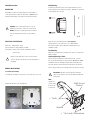
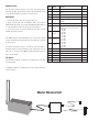
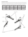
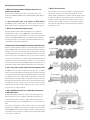
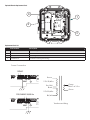
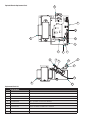
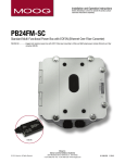
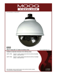
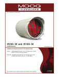
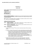
© 2011, Moog Videolarm, Inc. All Rights Reserved
PB24L900
Rugged Wireless Power Box
www.videolarm.com
Installation and Operation Instructions for the following model:
PB24L900
A rugged outdoor wireless box, with a 220/110Vac input and 24Vac output for camera, fuse protected. With a wireless 900MHz transmitter and matching receiver. Omni directional antenna.
Before attempting to connect or operate this product, please read these instructions completely.
81-IN5381
01-23-2012
IMPORTANT SAFEGUARDS
1
Read these instructions.
2
Keep these instructions.
3
Heed all warnings
4
Follow all instructions.
5
Do not use this apparatus near water.
6
Clean only with damp cloth.
7
CAUTION
RISK OF ELECTRIC SHOCK
DO NOT OPEN
Do not block any of the ventilation openings. Install in accordance with the
manufacturers instructions.
8
9
SAFETY PRECAUTIONS
Cable Runs- All cable runs must be within permissible distance.
CAUTION: TO REDUCE THE RISK OF
ELECTRIC SHOCK, DO NOT REMOVE
COVER ( OR BACK). NO USER- SERVICEABLE PARTS INSIDE. REFER SEVICING
TO QUALIFIED SERVICE PERSONNEL.
Mounting - This unit must be properly and securely mounted to a supporting
structure capable of sustaining the weight of the unit.
Accordingly:
a. The installation should be made by a qualified installer.
b. The installation should be in compliance with local codes.
c. Care should be exercised to select suitable hardware to install the unit, taking into
account both the composition of the mounting surface and the weight of the unit.
10 Do not install near any heat sources such as radiators, heat registers, stoves, or other
apparatus ( including amplifiers) that produce heat.
11 Do not defeat the safety purpose of the polarized or grounding-type plug. A
polarized plug has two blades with one wider than the other. A grounding type
plug has two blades and a third grounding prong. The wide blade or the third
prong are provided for your safety. When the provided plug does not fit into your
outlet, consult an electrician for replacement of the obsolete outlet.
12 Protect the power cord from being walked on or pinched particularly at plugs,
convenience receptacles, and the point where they exit from the apparatus.
13 Only use attachment/ accessories specified by the manufacturer.
14 Use only with a cart, stand, tripod, bracket, or table specified by the manufacturer,
or sold with the apparatus. When a cart is used, use caution when moving the cart/
apparatus combination to avoid injury from tip-over.
15 Unplug this apparatus during lighting storms or when unused for long periods of time.
16 Refer all servicing to qualified service personnel. Servicing is required when the
apparatus has been damaged in any way, such as power-supply cord or plug is
damaged, liquid has been spilled of objects have fallen into the apparatus, the
The lightning flash with an arrowhead symbol,
within an equilateral triangle, is intended to
alert the user to the presence of non-insulated
“dangerous voltage” within the product’s
enclosure that may be of sufficient magnitude
to constitute a risk to persons.
Este símbolo se piensa para alertar al usuario a la presencia
del “voltaje peligroso no-aisIado” dentro del recinto de los
productos que puede ser un riesgo de choque eléctrico.
Ce symbole est prévu pour alerter I’utilisateur à la presence
“de la tension dangereuse” non-isolée dans la clôture de
produits qui peut être un risque de choc électrique.
Dieses Symbol soll den Benutzer zum Vorhandensein der
nicht-lsolier “Gefährdungsspannung” innerhalb der
Produkteinschließung alarmieren die eine Gefahr des
elektrischen Schlages sein kann.
Este símbolo é pretendido alertar o usuário à presença “di
tensão perigosa non-isolada” dentro do cerco dos produtos
que pode ser um risco de choque elétrico.
Questo simbolo è inteso per avvertire I’utente alla presenza
“di tensione pericolosa” non-isolata all’interno della
recinzione dei prodotti che può essere un rischio di scossa
elettrica.
apparatus has been exposed to rain or moisture, does not operate normally, or
has been dropped.
Be sure to periodically examine the unit and the supporting structure to make sure that the integrity
of the installation is intact. Failure to comply with the foregoing could result in the unit separating
from the support structure and falling, with resultant damages or injury to anyone or anything struck
by the falling unit.
UNPACKING
Unpack carefully. Electronic components can be
damaged if improperly handled or dropped. If an item
appears to have been damaged in shipment, replace
it properly in its carton and notify the shipper.
Be sure to save:
1 The shipping carton and packaging material.
They are the safest material in which to make future
shipments of the equipment.
2 These Installation and Operating Instructions.
SERVICE
If technical support or service is needed, contact us at
the following number:
TECHNICAL SUPPORT
AVAILABLE 24 HOURS
1 - 800 - 554 -1124
The exclamation point within an equilateral
triangle is intended to alert the user to
presence of important operating and
maintenance (servicing) instructions in the
literature accompanying the appliance.
Este símbolo del punto del exclamation se piensa para
alertar al usuario a la presencia de instrucciones importantes
en la literatura que acompaña la aplicación.
Ce symbole de point d’exclamation est prévu pour alerter
l’utilisateur à la presence des instructions importantes dans
la littérature accompagnant l’appareil.
Dieses Ausruf Punktsymbol soll den Benutzer zum
Vorhandensein de wichtigen Anweisungen in der Literatur
alarmieren, die das Gerät begleitet.
Este símbolo do ponto do exclamation é pretendido alertar o
usuário à presença de instruções importantes na literatura
que acompanha o dispositivo.
Questo simbolo del punto del exclamaton è inteso per
avvertire l’utente alla presenza delle istruzioni importanti nella
letteratura che accompagna l'apparecchio.
Limited Warranty for Moog Videolarm Products
Moog Videolarm warrants these products to be free from defects in material or workmanship as follows:
PRODUCT CATEGORY
PARTS \ LABOR
All Enclosures and Electronics*
Five
Poles/PolEvators™/CamEvator
Three (3) Years
Warrior Series™/Q-View™/IR Illuminators
Five
(5) Years
SView Series™
Five
(5) Years **6 months if used in auto scan/tour operation
Controllers
Five
(5) Years
Power Supplies
Five
(5) Years
EcoKit
Three (3) Years
Accessory Brackets
Five
Liberty Dome
Three (3) Years
*DeputyDome™, NiteTrac™, Igloo Dome, PurgeDome™
Three (3) Years **6 months if used in auto scan/tour operation
(5) Years
(5) Years
During the labor warranty period, to repair the Product, Purchaser will either return the defective product, freight prepaid, or deliver it to Moog Videolarm
Inc. Decatur GA. The Product to be repaired is to be returned in either its original carton or a similar package affording an equal degree of protection with
a RMA # (Return Materials Authorization number) displayed on the outer box or packing slip. To obtain a RMA# you must contact our Technical Support
Team at 800.554.1124, extension 101. Moog Videolarm will return the repaired Product freight prepaid to Purchaser. Moog Videolarm is not obligated to
provide Purchaser with a substitute unit during the warranty period or at any time. After the applicable warranty period, Purchaser must pay all labor and/or
parts charges.
The limited warranty stated in these product instructions is subject to all of the following terms and conditions.
TERMS AND CONDITIONS
1. NOTIFICATION OF CLAIMS: WARRANTY SERVICE: If Purchaser believes that the Product is defective in material or workmanship, then written notice with an
explanation of the claim shall be given promptly by Purchaser to Moog Videolarm. All claims for warranty service must be made within the warranty period.
If after investigation Moog Videolarm determines the reported problem was not covered by the warranty, Purchaser shall pay Moog Videolarm for the cost of
investigating the problem at its then prevailing per incident billable rate. No repair or replacement of any Product or part thereof shall extend the warranty period
of the entire Product. The specific warranty on the repaired part only shall be in effect for a period of ninety (90) days following the repair or replacement of that
part or the remaining period of the Product parts warranty, whichever is greater.
2. EXCLUSIVE REMEDY: ACCEPTANCE: Purchaser’s exclusive remedy and Moog Videolarm’s sole obligation is to supply (or pay for) all labor necessary to repair any
Product found to be defective within the warranty period and to supply, at no extra charge, new or rebuilt replacements for defective parts.
3. EXCEPTIONS TO LIMITED WARRANTY: Moog Videolarm shall have no liability or obligation to Purchaser with respect to any Product requiring service during the
warranty period which is subjected to any of the following: abuse, improper use, negligence, accident, lightning damage or other acts of God (i.e., hurricanes,
earthquakes), modification, failure of the end-user to follow the directions outlined in the product instructions, failure of the end-user to follow the maintenance
procedures recommended by the International Security Industry Organization, written in product instructions, or recommended in the service manual for the
Product. Furthermore, Moog Videolarm shall have no liability where a schedule is specified for regular replacement or maintenance or cleaning of certain parts
(based on usage) and the end-user has failed to follow such schedule; attempted repair by non-qualified personnel; operation of the Product outside of the
published environmental and electrical parameters, or if such Product’s original identification (trademark, serial number) markings have been defaced, altered,
or removed. Moog Videolarm excludes from warranty coverage Products sold AS IS and/or WITH ALL FAULTS and excludes used Products which have not
been sold by Moog Videolarm to the Purchaser. All software and accompanying documentation furnished with, or as part of the Product is furnished “AS IS”
(i.e., without any warranty of any kind), except where expressly provided otherwise in any documentation or license agreement furnished with the Product. Any
cost associated with removal of defective product and installation of replacement product is not included in this warranty.
4. PROOF OF PURCHASE: The Purchaser’s dated bill of sale must be retained as evidence of the date of purchase and to establish warranty eligibility.
DISCLAIMER OF WARRANTY
EXCEPT FOR THE FOREGOING WARRANTIES, Moog Videolarm HEREBY DISCLAIMS AND EXCLUDES ALL OTHER WARRANTIES, EXPRESS OR IMPLIED,
INCLUDING, BUT NOT LIMITED TO ANY AND/OR ALL IMPLIED WARRANTIES OF MERCHANTABILITY, FITNESS FOR A PARTICULAR PURPOSE AND/OR
ANY WARRANTY WITH REGARD TO ANY CLAIM OF INFRINGEMENT THAT MAY BE PROVIDED IN SECTION 2-312(3) OF THE UNIFORM COMMERCIAL
CODE AND/OR IN ANY OTHER COMPARABLE STATE STATUTE. Moog Videolarm HEREBY DISCLAIMS ANY REPRESENTATIONS OR WARRANTY THAT
THE PRODUCT IS COMPATIBLE WITH ANY COMBINATION OF NON-Moog Videolarm PRODUCTS OR NON-Moog Videolarm RECOMMENDED PRODUCTS
PURCHASER MAY CHOOSE TO CONNECT TO THE PRODUCT.
LIMITATION OF LIABILITY
THE LIABILITY OF Moog Videolarm, IF ANY, AND PURCHASER’S SOLE AND EXCLUSIVE REMEDY FOR DAMAGES FOR ANY CLAIM OF ANY KIND
WHATSOEVER, REGARDLESS OF THE LEGAL THEORY AND WHETHER ARISING IN TORT OR CONTRACT, SHALL NOT BE GREATER THAN THE ACTUAL
PURCHASE PRICE OF THE PRODUCT WITH RESPECT TO WHICH SUCH CLAIM IS MADE. IN NO EVENT SHALL Moog Videolarm BE LIABLE TO PURCHASER
FOR ANY SPECIAL, INDIRECT, INCIDENTAL, OR CONSEQUENTIAL DAMAGES OF ANY KIND INCLUDING, BUT NOT LIMITED TO, COMPENSATION,
REIMBURSEMENT OR DAMAGES ON ACCOUNT OF THE LOSS OF PRESENT OR PROSPECTIVE PROFITS OR FOR ANY OTHER REASON WHATSOEVER.
PB24L900 Power Box
Wall Mounting:
A template is provided in the back of the instruction with the 2 x 8 bolt
DESCRIPTION
pattern required for the mounting of this product. Hardware is not provided
PB24L900 is an 84vA Power Supply, designed for either 230Vac or
for mounting this unit to the wall.
115vac input with 24Vac output. The unit includes a 900MHz wireless
transmitter and matching receiver with an omni-directional antenna.
!
CAUTION! These servicing instructions are for use by
qualified personnel only. To reduce risk of electric shock
DO NOT perform any servicing other than that contained
in the operating instructions unless you are qualified to
do so.
ELECTRICAL SPECIFICATIONS:
Wall
Attach the unit securely with (4) fasteners (not supplied).
Unit is designed to accept either 5/16”- 3/8" or 8mm hardware.
Input Power: 120Vac/240Vac 1A/.5A
Each fastener should be able to withstand a minimum pull out force
Power Consumption: 1Amp (120watts) at 120Vac
of 600 lbs. (272kg)
Power Output: 84VA at 24Vac, 52watts Heater/Blower, 32watts
Pole Mounting:
Camera Power
Optional pole mount brackets are available for the PB24. Pole adapter Part
Number is PBAP3.
!
An all pole main switch with a contact of at least 3mm in
Connecting Housing to PB24:
each pole shall be incorporated in the electrical installation of
Open the packet assembly that is provided with each unit. Special s”
the building.
bolts are provided and designed to mount either the WM20G or the WM10
(Standard Fusion Dome and Rugged Housing wall mount bracket) to the
Power Box. Attach the wall mount bracket and housing as shown below.
GENERAL INSTRUCTIONS:
ush the cable assembly connectors through either of the (2) holes provided.
Tools Required (minimum)
.150” Flathead Screwdriver, 7/16” wrench or socket, 9/16” wrench or socket
!
IMPORTANT! Unit will not seal properly unless installed as
shown. Do not attempt to use power box without installing wall
mount gasket.
NOTE:
Housing and
Included with the PB24 are the following items:
Wall Mount
Gasket
complete Power
Box not shown
for clarity only.
s ” Bolts
Washer
s ” Nut and Lockwashers
Connecting Power:
24VAC Power to Housing
(Detail)
H&B
H&B
Camera
Camera
Ground Post
Incoming Ground
24VAC
Power to
Housing
A
24VAC
Optional
Output
120VAC Input
GROUND
220-240VAC Input
CONNECTING POWER
Main On/Off Switch
Input: (120Vac or 240Vac)
The Power Box provides 2 separate power output(s) at 24V. The Power Box is
designed for either 120 or 240Vac input single phase. A single (3) position
connector is provided with each unit. Line and Neutral Wires should be
connected as marked on the connection board (L and N) and plugged in to
the connector plug of the corresponding voltage. Connect incoming ground to
ground post as shown above.
Finishing the Installation:
Once all wiring connections are completed; turn power the PB24 on and move
power switch to on position to ON position. Power LED on the connection pcb
should turn on.
Before closing the door on the PB24 check the main gasket around the lip of the
power box and be sure it is positioned within the groove provided. Close unit
and secure with (6) captive bolts provided. If needed (2) security screws are
!
Installation should be made by qualified personnel only, in
provided to lock and prevent tapering with internal components of the box. To
accordance to local building codes. Input power connections
install, remove (2) of the existing bolts and replace with (2) tamperproof security
should be made via conduit. Use flex LTF fitings for output only.
screws provided in the housing packet. Tighten with security wrench provided.
Output: (24Vac)
!
NOTE: Internal re-settable fuses are supplied for the main 24Vac
output lines. Fuse protection is higher for accessory power. Do
not connect heater and blowers to camera power output (marked
Camera) on Connection pcb.
NOTE: 3 PHASE SYSTEMS
!
The PB24 is NOT designed for 3 Phase or 208V systems. If a threephase or 208V system is in place, use volt meter to select one phase
120Vac LEG and connect to the 120Vac connection.
WIRELESS SETUP
LED
Name
Function
Color
Once the dome is installed and power is connected to it, the wireless master
1
Power
Unit has power and has successfully booted.
Red
unit must be installed. Below is the basic setup for the master RF unit. Please
2
RF Link
The radio has successfully linked with its
partner.
Green
3
RF TX
Radio transmission is occurring.
Green
4
RF RX
Radio reception is occurring.
Green
5
Eth Link
The Ethernet Port has a valid Ethernet
connection
Green
6
Activity
The WIRELESS UNIT is processing data
Green
7
1
channel)
Green
manually select the best channel
8
2
channel)
Each WIRELESS Master pair automatically selects the best radio channel,
9
4
(channel)
10
8
channel)
By adding the numbers that are lit the user
can determine the current radio channel.
1 903 MHz
2 905 MHz
3 907 MHz
4 909 MHz
5 911 MHz
6 913 MHz
7 915 MHz
8 917 MHz
9 919 MHz
10 921 MHz
11 923 MHz
12 925 MHz
transparent wireless point-to-point Ethernet cable replacement. Crossover
11
Link Quality
Excellent link quality – No retransmissions
Green
cables are not necessary as the WIRELESS UNIT automatically senses the
12
Link Quality
Very good link quality – Few retransmissions
Green
device (client or switch).
13
Link Quality
Good link quality – Some retransmissions
Amber
14
Link Quality
Fair link quality – Many retransmissions
Amber
LED display:
15
Link Quality
Weak link quality – Some packet failures
Red
Once the unit is operational, you should see the following colors on the LEDs
16
Link Quality
Poor link quality
Red
see the antenna installation section for proper antenna usage.
BASIC SETUP
1. Plug in the AC Power to the Power over Ethernet Injectors
2. Plug in the CAT5 cable from each WIRELESS UNIT into the injectors.
(NOTE: This unit can use both crossover cable and straight patch through cables.)
3. Connect the Ethernet cable from each injector into the Ethernet.
4. Use site survey mode to orient the antenna direction, and if necessary
encrypts the Ethernet traffic and transports the data wirelessly to and from
the wireless dome.
The wireless unit functions in place of an Ethernet cable and provides a
of the wireless unit.
The WIRELESS UNIT has a 16 LED display (see above chart) to display the
status of the device.
Master Wireless Unit
INSTALLATION:
should never try to point the ends of the antenna directly toward one another or directly
Once you have installed the antennas on the dome and master unit. You need to aim
away from one another. The 11dbi antennas are directional. They are designed so
the antennas so they are aligned with each other and they both have the same polarity. If
the radio wave will project directly out the front of the antenna. Because of this you
the antennas are too far away for visual alignment or there is obstacle in the way, please
should always point the 11dbi antennas directly at each other and never point them
refer to “site survey mode” listed on page 8 of this manual. Figure 2 shows some correct
away from each other. For a maximum range point-to-point (one unit). Videolarm
and incorrect methods of aligning the antennas. The 2.5dbi antenna is considered omni
recommends utilizing the auto-channel selection mode and maximum gain of 11dBi.
directional. They are designed so the radio wave will project out from the sides of the
Please refer to chart below.
antennas. The radio wave pattern will resemble a doughnut. Because of this patter you
Number of Pan and
tilt unit
DIP Setting
Antenna
Channel
Polarization
Frequency
1
All Off
11dBi
Auto 1-12
Vertical or Horizontal
903-925 MHz
Figure 2
RIGHT
WRONG!
Do not aim the 2.5 dbi antenna directly at
each other.
RIGHT
RIGHT
RIGHT
WRONG!
RIGHT
WRONG!
WRONG!
INSTALLING MULTIPLE ANTENNAS:
When installing more than one wireless unit in the same location, it is important to make sure that great care is taken to insure that the radio frequencies (channels) are
properly spaced apart. For tower applications with two or three wireless master units in close proximity on the same pole, Videolarm recommends utilizing the manual
channel mode; antenna gain of 11dBi and mixed polarization between antennas. It is recommended that antennae maintain a minimum of 4 ft of physical separation and
are oriented with greater than 45° of angular separation. If 45° of angular separation cannot be met, then it is recommend a minimum of 12 ft of physical separation.
Master unit
DIP Setting
Antenna
Channel
Polarization
Frequency
1
2 On / 3 Off
11dBi
Auto 1,2,3 or 4
Horizontal
903-909 MHz
2
2 On / 3 On
11dBi
Auto 9,10,11 or 12
Vertical
919-925 MHz
3
2 Off / 3 On
11dBi
Auto 5,6,7 or 8
Horizontal
911-917 MHz
Horizontal Polarization
0˚ separation
45˚ separation
4ft physical
separation
12ft physical
separation
Vertical Polarization
Up to 12 Radios –
Advanced tower installations with many pan and tilt units will require careful planning and assessment by a qualified radio technician. Videolarm recommends utilizing
the manual channel mode; antennae gain of 11dBi and mixed polarization between channels. It is recommended that antennae maintain a minimum of 4 ft of physical
separation and are oriented with greater than 45° of angular separation. If 45° of angular separation cannot be met, then it is recommend a minimum of 12 ft of physical
separation. Antenna polarization should be utilized to minimize adjacent channel saturation. Off-riggers and/or cavity filters might be necessary to achieve maximum
range with all 12 radios operating simultaneously from the same tower. Please refer to the chart below.
Master unit
DIP Setting
Antenna
Channel
Polarization
Frequency
1
5 On / 6 Off / 7 Off / 8 Off
11dBi
Fixed 1
Horizontal
903 MHz
2
5 On / 6 On / 7 On / 8 Off
11dBi
Fixed 7
Vertical
915 MHz
3
5 Off / 6 Off / 7 On / 8 On
11dBi
Fixed 12
Horizontal
925 MHz
4
5 On / 6 On / 7 Off / 8 Off
11dBi
Fixed 3
Vertical
907 MHz
5
5 On / 6 Off / 7 Off / 8 On
11dBi
Fixed 9
Horizontal
919 MHz
6
5 On / 6 Off / 7 On / 8 Off
11dBi
Fixed 5
Vertical
911 MHz
7
5 On / 6 On / 7 Off / 8 On
11dBi
Fixed 11
Horizontal
923 MHz
8
5 Off / 6 On / 7 Off / 8 Off
11dBi
Fixed 2
Vertical
905 MHz
9
5 Off / 6 Off / 7 Off / 8 On
11dBi
Fixed 8
Horizontal
917 MHz
10
5 Off / 6 Off / 7 On / 8 Off
11dBi
Fixed 4
Vertical
909 MHz
11
5 Off / 6 On / 7 On / 8 Off
11dBi
Fixed 6
Horizontal
913 MHz
12
5 Off / 6 On / 7 Off / 8 On
11dBi
Fixed 10
Vertical
921 MHz
FAQ (Frequently Asked Questions)
1. What is the maximum number of Ethernet devices that can
transmit across the link?
7. What is the Fresnel zone?
There is no limit to the number of client devices whose Ethernet traffic can be
spread out into after they leave the antenna. Typically, 20% Fresnel Zone
transported. The WIRELESS DOME supports an unlimited number of MAC addresses
blockage introduces little signal loss to the link. Beyond 40% blockage, signal
across the link.
loss will become significant. This calculation is based on a flat earth. It does
2.
Does you product have an IP address or MAC address?
The Fresnel Zone is the area around the visual line-of-sight that radio waves
not take the curvature of the earth into consideration. The effect of this is to
budge the earth in the middle of the link. It is recommended for long links to
The WIRELESS Pair has no MAC address, no IP address and no web interface. It
have a microwave path analysis done that takes this and the topography of
operates in place of a wire to send Ethernet traffic across the RF link in both directions.
the terrain into account.
3. What is the recommended antenna polarity?
Videolarm generally recommends horizontal polarization for most applications.
Most jamming noise sources in or near 900Mhz utilize vertical polarization. Our
experience indicates that successful installations often perform better with horizontal
polarization. The WIRELESS DOME will support horizontal and vertical installations
(the wall mount bracket does not currently support horizontal installation but can be
easily modified to enable horizontal polarization).
4. How do I use the Site Survey Mode to fine-tune the radio performance?
Radio noise is always a challenge for wireless systems, particularly those in unlicensed
bands. The WIRELESS Master has a built in site survey mode that allows the installer to
manually select any of the 12 channels and evaluate the link performance by reading
the LED link quality display. This mode sends simulated Ethernet traffic over the radio
link and reports the bit error rate (BER). This can be used to assist in the alignment
of antennas or to determine if there are in band or adjacent band interferers. The link
performance may show reduced link quality on channels 1 or 12 due to adjacent
channel noise. Under normal operation the WIRELESS Master automatically chooses a
channel with Strong link quality and will avoid channels that have poor performance.
5. Does your product include network-based management tools?
The WIRELESS Dome has built-in intelligent frequency agility. Upon receiving RF
interference, this allows the radio link to automatically change to a quieter channel based
on continuously monitoring of its own Bit Error Rate. With the channel selection feedback
loop running, the radio is able to always optimize the link without user intervention.
During installation we encourage testing of the radio link by using site survey mode
(DIP 4 ON). This testing will ensure that the radio has found channel(s) that achieve
a low BER. Once the link is tested, the user can turn off DIP 4 and let the link run
autonomously. The user then can ping a client device on the other side of the link to
ensure the radio is in continual operational.
6. Why is 900 MHz better than 2.4 or 5.8 GHz 802.11 for Non-Lineof-Sight applications?
The improved propagation characteristics of lower frequency RF energy has been
well documented for years. The 2.4 GHz and 5.8 GHz (802.11) frequencies are
excellent baseband carriers for clear line-of-sight conditions, however, they do not
propagate well through solids such as building walls, trees or over large expanses of
water.
The trade-offs are bandwidth vs. distance traveled - 802.11 can support higher
throughput (up to 54Mbps) but cannot travel far or through obstacles. By contrast,
Videolarm 900MHz technology can travel much greater distances through solids or air
for that matter, but can only support a 1.5 Mbps data rate (when the band is divided
into 12 channels - 2 MHz each).
Exploded View for Replacement Parts
4
1
A
2
3
Replacement Parts List
Part Number
Description
1
RP40HGPB1000
PB24 Housing Assembly
2
RP40BRPBL24
900 MHz Bracket Assembly With Transformer and PCB
3
RPPB241000
Grounding Stud and Terminal Connector
4
RP70WPPH13
3 Position Incoming Power Plug
Power Connection
120VAC
ON
120 VAC
Brown
220 VAC
INPUT
115V 50/60hz
Brn/Wht
Black
Green
24VAC at 3.5 a
Green
115V 50/60hz
220/240VAC 50/60 Hz
Blk/Wht
ON
120 VAC
220 VAC
INPUT
Transformer Wiring
Exploded View for Replacement Parts
9
1
5
2
8
6
7
8
7
9
3
4
4
5
6
3
2
Replacement Parts List
Part Number
1
RPVL2879
Wireless Base Bracket A
2
RP70TRANS11
96VA 220/110 TO 24 CE/UL TRANSFORMER
3
RPVL2885
Wireless box, bracket B
4
RP76PCBPB01
POWER BOX CONNECTION PCG
5
RP70WPPH08
3.81- 2 position Connector 1803578
6
RP70WPPH03
4 Position Connector 1803594
7
RP70CAPC02
12VDC POWER CONNECTOR - FEMALE
8
RP70AW9XB
Wireless 900 MHz Transmitter PCB
9
RP76RFPS
WIRELESS POWER SUPPLY PCB
1
Mounting
Template
8.00
[ 203.2 ]
2.00
[ 50.8 ]
Product Registration/Warranty
Thank you for choosing Moog Videolarm. We value your patronage and are solely committed to providing you with the highest
quality products available and superior customer service.
Should a problem arise, rest assure that Moog Videolarm stands behind its products by offering impressive warranty plans: 3 Years on all Housings, Poles,
Power Supplies, and Accessories and 5 Years on camera systems (SView, QView, Warriors), and InfraRed Illuminators.
Register Your Products Online
Take a few moments and validate your purchase via the Online Product Registration Form at
www.videolarm.com/productregistration.jsp
Register your recent Moog Videolarm purchases and benefit from the following:
• Simple and Trouble-Free RMA process
• Added into customer database to receive product updates / news
• Eliminate the need to archive original purchase documents:
Receipts, Purchase Orders, etc…
15