1
DT-X7 Series
Software Manual
(Version 1.00)
CASIO Computer Co., Ltd.
Copyright ©2007. All rights reserved.
August 2007
Table of the Contents
Editorial Record
Chapter 1.
Overview
1.1.
Model by Feature
1.2.
Available Options
1.3.
Application Development Environment
Chapter 2.
Functions
2.1.
Basic Functions
2.1.1.
WindowsCE Version 5.0
2.1.2.
Displays
2.1.3.
Keys
2.1.4.
Audio
2.1.5.
Buzzer
2.1.6.
Memory Management
2.1.7.
LED
2.1.8.
Vibrator
2.2.
Scanner
2.2.1.
Basic Specifications
2.2.2.
Scanning Method
2.2.3.
Scanning Parameters
2.2.4.
Scanning Output Format
2.2.5.
Scan Result Notification
2.2.6.
Expanded Features
2.2.7.
Power Control
2.3.
USB
2.3.1.
Basic Specifications
2.3.2.
COM Port
2.3.3.
Product ID
2.4.
IrDA
2.4.1.
Communication Speeds
2.4.2.
COM Port
2.5.
Bluetooth
2.5.1.
Basic Functions
2.5.2.
Communication Profiles
2.5.3.
Security
2.5.4.
COM Port
2.5.5.
Communication Procedures
2.5.6.
Communication Procedures by Profile
2.5.7.
Process after Communication Interruption
2.5.8.
Processing During Suspend and Resume
2.5.9.
Setting SR Mode Parameter
2.5.10. WakeOn Bluetooth Function
2.6.
WLAN
2.6.1.
Basic Specifications
2.6.2.
Expanded Features
2.6.3.
Roaming
2.6.4.
Zeroconfig
2.6.5.
Channels
2
6
7
7
8
9
10
10
10
17
19
26
27
28
29
31
32
32
34
35
37
45
46
50
51
51
52
52
53
53
53
54
54
55
56
56
57
58
59
59
59
60
61
61
62
63
64
65
2.6.6.
2.7.
2.7.1.
2.7.2.
2.7.3.
2.7.4.
2.7.5.
2.7.6.
2.7.7.
2.8.
2.8.1.
2.8.2.
2.8.3.
2.8.4.
Chapter 3.
3.1.
3.1.1.
3.1.2.
3.1.3.
3.1.4.
3.1.5.
3.1.6.
3.1.7.
3.1.8.
3.1.9.
3.1.10.
3.1.11.
3.1.12.
3.1.13.
3.1.14.
3.1.15.
3.1.16.
3.1.17.
3.1.18.
3.1.19.
3.1.20.
3.1.21.
3.1.22.
3.1.23.
3.1.24.
3.1.25.
3.1.26.
3.1.27.
3.1.28.
3.1.29.
3.2.
3.2.1.
3.2.2.
3.2.3.
3.2.4.
WLAN Setting with Configuration File
Power Control
Low Voltage Monitoring
Power ON Factors
Power OFF Factors
Power Saving
CPU Power State Control
Charging, Supplying the Power
Temperature Control
Security
Setting Password for Terminal
Setting Password for Date and Time Properties
Setting Individual ID
Setting Distributor ID
Application
Control Panel Applets
Bluetooth Connection
WLAN Power
WLAN Settings
CPU Speed
PC Connection
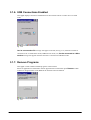
USB Connections Enabled
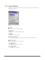
Remove Programs
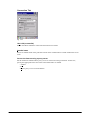
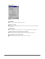
Internet Options
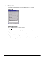
Keyboard
System
Terminal Server Client Licenses
Dialing
Network and Dial-up Connections
Version Info
Vibrator
Password
Power
Buzzer
Volume & Sounds
Mouse
Scanner Setting
Display
Storage Manager
Owner
Certificates
Regional Settings
Date and Time
Input Panel
Brightness
Application Programs
Internet Explorer
TextEditor
Explorer
Command Prompt
3
65
69
69
70
71
72
73
75
76
77
77
77
77
77
78
79
81
82
83
92
93
94
94
95
101
102
104
105
107
110
111
112
113
116
117
118
118
123
125
126
129
130
132
133
134
138
139
141
142
144
3.2.5.
3.2.6.
3.2.7.
3.2.8.
3.2.9.
3.2.10.
3.2.11.
3.2.12.
3.2.13.
3.2.14.
3.3.
3.3.1.
3.3.2.
3.3.3.
3.3.4.
3.3.5.
3.4.
3.4.1.
3.4.2.
3.4.3.
Remote Desktop Connection
Voice Recorder
Laser Scanner Demo
Laser Scanner Read
Copy Devices
FLCE
ActiveSync
LAN ActiveSync
Terminal
NetSearch
Utilities
FCHKCE
Auto Setup
Auto Recovery Tool
Welcome Wizard
Input Panel (SIP)
Application
ActiveSync
LMWIN
FCHK
4
145
147
148
148
149
152
153
153
154
156
160
160
160
162
163
163
164
164
164
164
No part of this document may be produced or transmitted in any form or by any means, electronic
or mechanical, for any purpose, without the express written permission of CASIO Computer Co.,
Ltd. in Tokyo Japan. Information in this document is subject to change without advance notice.
CASIO Computer Co., Ltd. makes no representations or warranties with respect to the contents or
use of this manual and specifically disclaims any express or implied warranties of merchantability
or fitness for any particular purpose.
© 2007 CASIO Computer Co., Ltd. All rights reserved.
5
Editorial Record
Manual
Version no.
0.90
1.00
Date edited
Page
Content
May 2007
August 2007
Tentative version
Original version
6
1. Overview
The features and specifications described in this reference manual give an overview of the
functional detailed specifications of the DT-X7 series handheld terminal.
1.1. Model by Feature
The features integrated in each model of the DT-X7 series are shown below.
Table 1.1
Model
Laser scanner
Linear Imager
DT-X7M10U
DT-X7M10E
DT-X7M10R
DT-X7M10E-CN
DT-X7M10R-CN
No
Yes
Yes
Yes
Yes
Yes
No
No
No
No
7
Bluetooth
Class 1
Yes
No
No
No
No
Bluetooth
Class 2
No
Yes
Yes
Yes
Yes
WLAN
No
No
Yes
No
Yes
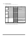
1.2. Available Options
The following dedicated options are available for DT-X7 series.
Table 1.2
Option
Cradle
Product
USB Cradle
Ethernet Cradle
Dry-cell Battery Case
Battery
Battery Pack
Large-capacity Battery Pack
Battery
charger
Dual Battery Charger
Cradle-type Battery Charger
AC adaptor
Others
Cradle-type Dual Battery
Charger
AC adaptor
Hand Belt
Model no.
HA-F60IO
HA-F60IO-CN
HA-F62IO
HA-F62IO-CN
HA-F22BC
HA-F22BC-CN
HA-F20BAT
HA-F20BAT-CN
HA-F21LBAT
HA-F21LBAT-CN
HA-F32DCHG
HA-F32DCHG-CN
HA-F30CHG
HA-F30CHG-CN
HA-F36DCHG
HA-F36DCHG-CN
AD-S15050BE
AD-S15050BE-CN
AD-S42120BE
AD-S42120BE-CN
AD-S60160BU
AD-S60160BE
AD-S60160BE-CN
HA-F95HB
Remark
With USB interface and the power supply
terminals
With LAN and USB interface and the
power supply terminals
Maximum 3 chargers can be connected.
Maximum 3 chargers can be connected.
For HA-F30CHG, HA-F30CHG-CN
For HA-F60IO, HA-F60IO-CN,
HA-F62IO, HA-F62IO-CN
For HA-F32DCHG, HA-F32DCHG-CN,
HA-F36DCHG, HA-F36DCHG-CN
Note:
Refer to DT-X7 Series Hardware Manual (Chapter 1, Table 1.2) for the dedicated options with
“-CN” denotation complaint with the Chinese RoHS requirement.
8
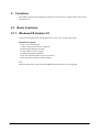
1.3. Application Development Environment
Development platform
• Microsoft Windows 2000 (SP2 or later release)
• Microsoft Windows XP
Development environment
• Visual Studio .NET 2003+WindowsCE Utilities for Visual Studio .NET 2003 Add-on Pack 1
• Visual Studio 2005
• eMbedded Visual C++ 4.0 +SP4
Development environment
• DT-X7 Export SDK
9
2. Functions
This chapter describes about detailed specifications of the functions implemented in the terminal
and the options.
2.1. Basic Functions
2.1.1. WindowsCE Version 5.0
The terminal integrates Microsoft WindowsCE Version 5.0 as its operating system.
Features at a glance
• Easy-to-use user interface
• .NET Compact Framework is supported
• High-speed multitask processing
• Large capacity memory support
• Abundant peripheral equipment
• Easy development thanks to open environment
• PPC application operation with AYGShell
Note:
Microsoft applications such as PocketWORD and PocketEXCEL are not integrated.
10
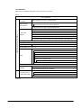
Core Modules
Microsoft core modules integrated in the terminal are as follows.
Table. 2.1
Core OS Modules
.NET Compact
Framework
.NET Compact Framework 1.0 Related Matters
.NET Compact Framework 2.0
.NET Compact Framework 2.0 Strincg Resources
OS Dependencies for .NET Compact Framework 2.0
String Safe Utility Function
Complete C runtime
C library and
Standard Input/Output (STDIO)
Runtime
Standard Input/Output ASCII (STDIOA)
Standard Character String Function - ASCII (corestra)
C++ Runtime Support for Exception Processing and Runtime Type Information
LDAP (Lightweight Directory Access Protocol) Client
Microsoft Foundation Classes (MFC)
SOAP Toolkit
Client
Standard SDK for Windows CE
MSXML 3.0
XML Core Service and Document Object Model (DOM)
XML HTTP
XML SAX
XML
XML Error Character String
XML Query Language (XQL)
XML Style Sheet Language Transformation (XSLT)
XML Minimum Passer
Active Template Library (ATL)
Message Queue
MSMQ ActiveX Wrapper
(MSMQ)
SOAP Reliable Message Protocol (SRMP)
COM
Component Service
COM Storage Area
(COM and DCOM)
CoCreateGuid Function for OLE32
DCOM
Applications and Services Development
.NET Compact
Framework 2.0
Continue.
11
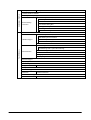
Applications - End User
ActiveSync
File Sync
CAB File Installer/Uninstaller
FLASH Update Sample Application
Remote Desktop Protocol (RDP)
Audio Playback Redirect
Serial and Parallel Port Redirect
Remote Desktop
User Interface Dialog Box
Connection
Cut/Copy/Paste Clipboard Redirect
File Storage Area Redirect
Filtered File Storage Area Redirect
PNP Notification
USB Human Input Device (HID) Class Driver
USB HID Keyboard and Mouse
USB HID Keyboard Only
USB Host Support
USB HID Mouse Only
Core OS Services
USB Printer Class Driver
Kernel Functions
FormatMessage API
FormatMessage API - System Error Message
Target Control Support (Shell.exe)
Fiber API
Message Queue - Point-To-Point
Memory Map File
Serial Port Support
Display Support
Device Manager
Debug tool
Tool Hint API
Battery Driver
Parallel Port Support
Notification
UI Base Notification
Notification LED Support
Power Control
Power Control (full)
Continue.
12
Server
Communication Services and Networking
Network - Local Area
Network (LAN)
Network - Personal
Area Network (PAN)
Network - Wide Area
Network (WAN)
Fonts
File Systems and Data Store
Network Functions
System Password
Database Support
File system - Internal
Duplication of File and
Database
Registry Storage Area
Compression
Storage Area Manager
Courier New
Tahoma
Times New Roman
Wingding
Simple Network Time Protocol (SNTP)
SNTP Client With DST
Web Server (HTTPD)
Core Server Support
Native Wi-Fi WLAN STA
Wired Local Area Network (802.3, 802.5)
Wireless LAN (802.11) STA - Auto Configuration and 802.1x
IrDA
Telephony API (TAPI 2.0)
Unimodem support
Ethernet Point-To-Point Protocol (PPPoE)
Dial Up Network (RAS/PPP)
Standard Modem Support for Dial Up Network
Auto Dial
Virtual Private Network
L2TP / IPSec
PPTP
IPSec v4
NDIS User Mode I/O Driver
TCP/IP
IP help API
TCP/IPv6 support
Windows Network API/Redirect (SMB/CIFS)
Winsock Support
Network Driver Configuration (NDIS)
Expandable Authentication Protocol
File System Applicable for RAM and ROM
Bit Base
Hive Base Registry
EDB Database Engine
FAT File System
Partition Driver
Storage Area Manager Control Panel Applet
Courier New (Subset 1_30)
Tahoma (Subset 1_07)
Times New Roman (Subset 1_30)
Continue.
13
International
Internet Client Services
Internet Client Services
Local Service
Support for Languages (NLS)
Input System Manager (IMM)
Pocket Internet Explorer HTML View (WEBVIEW)
Internet Explorer HTML/DHTML API
Internet Explorer HTML Application
Internet Explorer Theme Library
Internet Explorer Plug In Image Decoder API
Internet Explorer PNG Image Decoder
Filter and Translation
Internet Explorer RPC Support
Internet Explorer TV Style Navigation
Customizable Font Range
Internet Explorer 6.0
Fixed Width Layout
Component for
Disable Vertical Scroll Bar and Event
WindowsCE
Direction Tab
Internet Explorer Browser Control Host
Basic API Supporting Multilingual Internet Explorer
Full API Support for Multilingual Internet Explorer
Character Set/Encode of Options in Registry
URL Moniker Service
Windows Internet Service
P3P (Platform for Privacy Preferences)
Passport SSI 1.4 Authentication
Control Panel’s [Internet Option]
JScript 5.6
Script Encode (Jscript)
Script Authoring (Jscript)
script
VBScript 5.6
MsgBox and InputBox Support
Script Encode (VBScript)
Script Authoring (VBScript)
Internet Explorer 6.0 for WindowsCE - Standard Component
Browser Application
Internet Explorer 6.0 Sample Browser
TV Style Navigation Component
Continue.
14
Multimedia Technologies
Security
Shell and User Interface
Waveform Audio
Audio Compression Manager
Audio
GSM 6.10 Codec
MSFilter Codec
DirectDraw
Imaging
Static Image Codec Support (Encode and Decode)
Static Image Encoder
BMP Encoder
GIF Encoder
JPG Encoder
Graphics
PNG Encoder
Static Image Dencoder
BMP Decoder
GIF Decoder
ICO Decoder
JPG Decoder
PNG Decoder
Gradation Support
Microsoft Certificate Registration Tool Sample
Local Authentication
Password Local Authentication Plug in
Subsystem
Diffie-Hellman/DSS Provider
Powerful Encrypting
Provider’s Encrypting
Certificate (CryptoAPI 2.0)
Service
Personal Information Exchange Standard (PKCS #12)
(CryptoAPI 1.0)
Encryption Messaging (PKCS #7)
Capability Information Manager
Kerberos
Authentication Service
NTLM
(SSPI)
Schannel (SSL/TLS)
Minimum GDI Configuration
Graphics, Windowing
Minimum GWES Configuration
and Event
Minimum Window Manager Configuration
Minimum Input Configuration
AYGShell API Set
Graphic Shell
Standard Shell
Shell
Command Shell
Command Processor
Console Window
Continue.
15
Shell and User Interface
User interface
Quarter VGA Resource Longitudinal Mode
Control Panel Applet
Software Input Panel
Software Base Input Panel (SIP)
SIP for Small Screen
Software Base Input Panel Driver
Network User Interface
Shared Control
Shared Control
Shared Dialog Support
16
2.1.2. Displays
Basic Specifications
The QVGA (320 x 240 dots) mode is supported for the terminal. The control panel can be used to
switch between the VGA and QVGA modes, and the switching the display mode is initiated when
a reset is performed.
Table. 2.2
Display specification
Display size
X direction
Y direction
65,536 colors 2-way TFT (16 bpp, Red: 5 bits, Green: 6 bits, Blue: 5 bits)
240 dots
320 dots
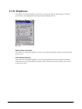
Backlight brightness
A brightness of the backlight can be changed in the control panel.
• Setting can be made in one of nine grades for power source either when the power is provided
by an external power supply (via cradle with AC adaptor connected) or when the power is
provided by the installed lithium-ion battery pack.
• Setting can be made in application by using ExtEscape()API function.
• If the brightness is set to 1 (minimum), the backlight is turned off.
• The default is 9 (maximum) when an external power source is used or 7 when lithium-ion
battery pack is used.
17
Backlight Auto Dimming
The control panel can be used to set up whether or not the auto dimming function will be used and
the waiting time until when dimming begins. Auto dimming is enabled only when the power is
provided by the lithium-ion battery pack. It will not function when an external power supply is
used.
• If the terminal is left over in idle state - absolutely no key input - while the power is turned on,
the backlight will be automatically dimmed to save the power after a given period of time has
been elapsed.
• When the terminal is in the auto dimmed state, a press of key will disable the auto dimming
function to resume the brightness.
• While the auto dimming function has been set enabled, brightness can be set in one of eight
grades. The default is 3.
During the auto dimming function being set enabled, brightness cannot be set any brighter than
the brightness illuminated by the backlight. The defaults are “Enable the auto dimming function”
and “1 minute” for waiting time period until when the auto dimming function activates.
Auto Backlight OFF
The control panel can be used to set up whether or not the Auto Backlight OFF function will be
used and the waiting time until when the Auto Backlight OFF function activates. The Auto
Backlight OFF function is operable for both when the power is provided by an external power
source and when it is provided by lithium-ion battery pack.
• If the terminal is left over in idle state - absolutely no key - with the power being turned on,
the backlight will be automatically turned off to save energy.
• When the terminal is in the Auto Backlight OFF state, a press of key will disable the Auto
Backlight OFF function to resume the brightness.
• While the power is being provided by lithium-ion battery pack and both the auto dimming
function and the Auto Backlight OFF function have been set enabled, either one of the
functions with preset time period shorter than the other will have the priority. The default is
“Enable the Auto Backlight OFF function” and “5 minutes for the waiting time” until when
the Auto Backlight OFF function activates.
Rotating Display
The rotate display function for rotating the screen at 90, 180 or 270 degree is supported.
• The Common Device Control Library can be used to set up in the application.
• ChangeDisplaySettingEx() API function can be used to set up this display rotation feature
in application.
See Microsoft Help for details about ExtEscape() and ChangeDisplaySettingEx() API
functions.
18
2.1.3. Keys
Keyboard Layout
The following is the keyboard layout employed in the DT-X7.
Fig. 2.1
19
Key Assignments
The following are the key codes and functions assignments.
Table. 2.3 Control keys
KEY
Input mode
Operation
----
Specialized key operation (toggle)
Remarks
Fn mode is released
when a key input is
Fn
made.
Character input mode
CLR
1
Deletes 1 character to the left.
A
Deletes 1 character to the left.
a
Deletes 1 character to the left.
P
Deletes 1 character to the left.
Function mode
F
Perform as “ESC operation”.
Character input mode
1
Perform as “Enter key”.
A
Perform as “Enter key”.
a
Perform as “Enter key”.
P
Perform as “#”.
Function mode
F
Perform as “Shift and Enter keys”.
Character input mode
1
Perform as “Cursor up key”.
A
Perform as “Cursor up key”.
a
Perform as “Cursor up key”.
↑
P
Perform as “Cursor up key”.
Function mode
F
Perform as “Shift and TAB keys”.
Character input mode
1
Perform as “Cursor down key”.
↓
Function mode
A
Perform as “Cursor down key”.
a
Perform as “Cursor down key”.
P
Perform as “Cursor down key”.
F
Perform as “TAB key”.
20
Table. 2.4 Trigger key
KEY
Input mode
Operation
1
Center trigger
Character input mode
A
a
P
Function mode
F
Remarks
Perform as “Trigger key”.
Perform as “Trigger key”.
Perform as “Trigger key”.
Perform as “Enter key”.
Perform as “Trigger key”.
Table. 2.5 Ten key
KEY
Input mode
Character input mode
0
Operation
1
Perform as “0”.
A
Perform as “-_/^\&=+$%#* space”.
a
Perform as “-_/^\&=+$%#* space”.
P
Perform as “0”.
Function mode
F
Display or not display SIP.
Character input mode
1
Perform as “1”.
A
Perform as “?!()<>[]{}”.
1
Function mode
Character input mode
2
a
Perform as “?!()<>[]{}”.
P
Perform as “1”.
F
Turn on or off the backlight.
1
Perform as “2”.
A
Perform as “ABC”.
a
Perform as “abc”.
P
Perform as “2”.
Function mode
F
No effect.
Character input mode
1
Perform as “3”.
A
Perform as “DEF”.
3
Function mode
Character input mode
a
Perform as “def”.
P
Perform as “3”.
F
No effect.
1
Perform as “4”.
A
Perform as “GHI”.
a
Perform as “ghi”.
P
Perform as “4”.
Function mode
F
Initiate the calibration.
Character input mode
1
Perform as “5”.
A
Perform as “JKL”.
4
5
Function mode
Character input mode
6
Function mode
a
Perform as “jkl”.
P
Perform as “5”.
F
Darken the backlight.
1
Perform as “6”.
A
Perform as “MNO”.
a
Perform as “mno”.
P
Perform as “6”.
F
Brighten the backlight.
Continue.
21
Remarks
Character input mode
7
Function mode
1
Perform as “7”.
A
Perform as “PQRS”.
a
Perform as “pqrs”.
P
Perform as “7”.
F
Initiate application registered in the registry below.
[HKEY_LOCAL_MACHINE\HARDWARE\DEVICEMAP\KEYBD]
Fn7LaunchPaht:sz (path of the application to be initiated)
Character input mode
8
Function mode
1
Perform as “8”.
A
Perform as “TUV”.
a
Perform as “tuv”.
P
Perform as “8”.
F
Initiate application registered in the registry below.
[HKEY_LOCAL_MACHINE\HARDWARE\DEVICEMAP\KEYBD]
Fn8LaunchPaht:sz (path of the application to be initiated)
Character input mode
9
Function mode
1
Perform as “9”.
A
Perform as “WXYZ”.
a
Perform as “wxyz”.
P
Perform as “9”.
F
Initiate application registered in the registry below
[HKEY_LOCAL_MACHINE\HARDWARE\DEVICEMAP\KEYBD]
Fn9LaunchPaht:sz (path of the application to be initiated)
Character input mode
.
Function mode
1
Perform as “.”.
A
Perform as “@.,”’`:;~|”.
a
Perform as “@.,”’`:;~|”.
P
Perform as “*”.
F
Perform as “-”.
22
Key Input Mode Switchover
The A key on the keyboard can be used to change the key input mode.
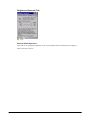
Indication of Key Input Mode
Key input mode currently specified appears in the task tray. The modes that can be displayed are
“L” as Lock, “F” as function, “1” as numeral, “A” as alphabets in uppercase, “a” as alphabets in
lowercase, and “P” as telephone.
L
F
1
A
a
P
Fig. 2.2
Turnover Key Auto Confirmation
After inputting a turnover key, if the preset time period has been elapsed from the time when the
turnover key is released, the turnover character input will be automatically made. The control
panel can be used to set up “enable” or “disable” for the auto confirmation on the turnover
character input and to set up the time period until when its confirmation is made.
Key Repeat
Continued pressing of any of “0” to “9”, “ ↑“, “←”, “→”, and “ ↓“ keys will repeat the key input.
Key Click Sound
The key click sound is generated when a key is pressed. However, it is not generated when the key
is released or in mid-course of repeating the key input. The control panel can be used to set up the
sound to mute, low or loud.
23
Enabling or Disabling Fn Key
For keys that perform specialized operations while the key input mode has been set to Function
mode, “Enable” or “Disable” can be set on each individual key in the registry below to control the
operations.
[HKEY_LOCAL_MACHINE\HARDWARE\DEVICEMAP\KEYBD]
Or, using the SysSetFnKeyOperation and SysSetFnKeyOperation functions of either
Common Device Control Library or Common Device Control Class Library can achieve the same
control operation explained above.
Table. 2.6
Key
DisableFn9
DisableFn8
DisableFn7
DisableFn6
DisableFn5
DisableFn4
DisableFn3
DisableFn2
DisableFn1
DisableFn0
Setting Value
dword: 0 or 1
dword: 0 or 1
dword: 0 or 1
dword: 0 or 1
dword: 0 or 1
dword: 0 or 1
dword: 0 or 1
dword: 0 or 1
dword: 0 or 1
dword: 0 or 1
Meaning
Enable or Disable
Enable or Disable
Enable or Disable
Enable or Disable
Enable or Disable
Enable or Disable
Enable or Disable
Enable or Disable
Enable or Disable
Enable or Disable
Function Mode Notification
When the Fn key is pressed, the WM_USER+0x502 message is issued to the application. This
enables the application to detect whether the Function mode has been set up enabled or disabled.
Enable or Disable the A Key
The device library can be used to make the setting on “Enable” or “Disable” for switching over
the key input mode in application.
A Key Notification
When the A key is pressed, the WM_USER+0x506 message is issued to the application. Using
this notification, the application can detect whether the key input mode has been changed.
Permit or Prohibit Key Locks
The device library can be used to permit or prohibit the operations of keys except for the Power
and Trigger keys.
24
User Settable Keys
• Initiating application
The following registry can be used to assign any application to the Fn+7, Fn+8 and Fn+9 keys.
[HKEY_LOCAL_MACHINE\HARDWARE\DEVICEMAP\KEYBD]
Table. 2.7
Key
Fn7LaunchPath
Fn8LaunchPath
Fn9LaunchPath
Setting Value
sz: Target application in full path to initiate
sz: Target application in full path to initiate
sz: Target application in full path to initiate
• Setting key codes
The Common Device Control Library can be used to assign any key code to all the keys except
the Fn key. Setting on “Enable” or “Disable” for assigning key code is possible either using the
Common Device Control Library or at the control panel.
• The key codes after setting are valid only when the numeral input mode is set enabled.
25
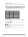
2.1.4.
Audio
Basic Specifications
WAV playback, voice recording and playback are supported.
When headphones are being used, playback from the speaker is halted. Stereo data is converted
into mono data and then output. By using the Microsoft SoftwareMixer function, output sounds
from multiple applications can be mixed and output (in 44.1 KHz, 16-bit stereo mixing).
Voice Recorder is integrated in the terminal as the sound system application to make it possible to
perform WAV file streaming playback and local file playback in HTTP.
Playback
Table. 2.8
Sampling
frequencies
Stereo, Mono
KHz
8
11.025
12
16
22.05
24
Mono
Yes
Yes
Yes
Yes
Yes
Yes
Stereo
Yes
Yes
Yes
Yes
Yes
Yes
Sampling frequencies other than those above are not supported.
8-bit or 16-bit
In reality, mono speakers do not playback in stereo.
32
Yes
Yes
44.1
Yes
Yes
48
Yes
Yes
KHz
8
11.025
12
16
22.05
24
Mono
Yes
Yes
Yes
Yes
Yes
Yes
Sampling frequencies other than those above are not supported.
8-bit or 16-bit
Mono input only via microphone
32
Yes
44.1
Yes
48
Yes
Recording
Table. 2.9
Sampling
frequencies
Stereo, Mono
Setting Sound Volume
The control panel can be used to set up sound volume in six grades from loud to low and ON/OFF
of mute. A sound volume also can be set up using Win32 API function in application.
Audio ON/OFF
The audio system can be disabled to save the power. Enable or disable for the audio system in the
terminal is controlled using the Common Device Control Library in application.
26
2.1.5.
Buzzer
Basic Specifications
The buzzer can be used to output various sounds such as scanning confirmation, alarm, warning
and any other available sounds.
The sounds have the following four attributes and default values.
Table. 2.10
Alarm sound
Warning sound
Scan end sound
User designated sound
Frequency
(Hz)
3500
3000
3300
--
Time
(millisecond)
150
100
75
--
Individual Mute
Attribute
ON or OFF
ON or OFF
ON or OFF
ON or OFF
B_ALARM
B_WARNING
B_SCANEND
B_USERDEF
Setting Volume
The control panel can be used to set up volume in three grades from loud, medium and low and
ON/OFF of mute. Setting the volume is also possible using the Common Device Control Library
in application.
27
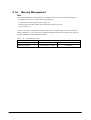
2.1.6.
Memory Management
RAM
The integrated RAM has a total capacity of 64 Mbytes and is used for the following purposes.
• Program memory to be used by the OS and programs.
• Object store used for temporary file saving, etc.
• Other program and OS resident areas beyond the control by the OS
• Driver work area
The user can make unrestricted use with the object store, but data stored in it may be lost due to
battery exhaustion, etc. To avoid such incident it should be used just as a temporary storage area,
and use FlashDisk to store important data files.
Table. 2.11 Initial memory status
Memory
Program memory capacity
Object store capacity
Initial Status
Total capacity; 27.6 MB
Total capacity; 13.7 MB
28
6.5 MB used
0.3 MB used
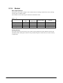
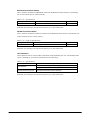
2.1.7. LED
Basic Specifications
There are two LEDs integrated in the terminal, one for the user notification on the right and the
other for charging the battery complete on the left.
Table. 2.12
LED
Right-side LED
Left-side LED
Color
Red
Green
Blue
Orange
Purple
Sky blue
Red
Green
Description
User notification (alarm), scanning a bar code
Scanning a bar code
Connection established via Bluetooth
Connection established via WLAN
None
None
Charging battery pack
Charging battery pack complete
Notes:
• The user notification LED can be used to indicate various notifications by the OS and other
notifications defined by the user.
• All colors available in the LEDs are indicated by using the Common Device Control Library.
• The charging battery complete LED cannot be controlled for its ON/OFF state with software.
User Notification (Alarm)
This indication mode is used for alarm notification, etc. The LED can be lit for a specific time
using CeSetUserNotification()API function.
Table. 2.13 Specifications
Operating mode
Blink interval
Continuous ON time
Specification
ON for 1 second in red, OFF for 2 seconds
ON for 30 minutes (OFF when VDET is detected.)
Note:
Indication for scanning a bar code has the priority over other indications.
Scanning
This is used for notification of a scanning result which is controlled by use of the Common Device
Control Library.
Table. 2.14 Specifications
Operating mode
Scanning complete
Scanning in error
Specification
ON in green for a specified period of time, then OFF.
ON in red for a specified period of time, then OFF.
29
Attribute
L_SCANOK
L_SCANERR
Bluetooth Connection Status
This is used for notification of Bluetooth connection establishment status which is controlled by
use of the Common Device Control Library.
Table. 2.15 Specifications
Operation mode
Bluetooth established
Specification
ON in blue for 1 second, OFF for 2 seconds
Attribute
L_BT
Note:
Indication for scanning a bar code has the priority over other indications.
WLAN Connection Status
This is used for notification of WLAN connection establishment status which is controlled by use
of the Common Device Control Library.
Table. 2.16 Light up specifications
Operation mode
WLAN established
Specification
ON in orange for 1 second, OFF for 2 seconds
Attribute
L_WLAN
Note:
Indication for scanning a bar code has the priority over other indications.
User Definition
This indication mode is used for other notifications freely defined by the user. The ON/OFF state
can be controlled by use of the Common Device Control Library.
Table. 2.17 Specifications
Operation mode
User definition
Continuous ON time period
Specification
Color selection from green, blue, orange, purple or sky blue.
Programmable for ON and OFF time periods
30 minutes (OFF when VDET is detected)
Note:
Indication for scanning a bar code has the priority over other indications.
30
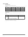
2.1.8. Vibrator
Basic Specifications
The vibrator can be set up for five different occasions.
Table. 2.18
Occasion
Alarm
Warning
Barcode scan complete
Wireless incoming signal
User definition
Vibration Pattern
Default
Default
Default
Default
User
Setting
ON or OFF
ON or OFF
ON or OFF
ON or OFF
ON or OFF
Default
OFF
OFF
OFF
OFF
OFF
Vibration Interval
The vibration interval can be set in two different patterns, the default setting and a user defined
setting.
Table. 2.19
Pattern
Default
User
definition
Vibration Interval
“ON for 1 second, OFF for 1 second” x [times]
“Specified ON period, Specified OFF period” x
[times]
Setting range; 1/16 seconds to 16 seconds for ON
period, 1/16 seconds to 1 second for OFF period
Remarks
Maximum no. of times; 20
Maximum no. of times; 20
The Common Device Control Library can be used to control ON/OFF state for each occasion of
the vibration and the vibration interval in user definition.
31
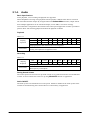
2.2. Scanner
2.2.1. Basic Specifications
The following industrial standard bar code symbologies are supported by the laser scanner.
Table. 2.20 Supported symbologies
Symbology
EAN, JAN,UPC-A/B
EAN, JAN,UPC-A/B Addon
UPC-E
UPC-E Addon
Code39
NW-7
Interleaved 2of5
Industrial 2of5
Code93
Code128
MSI
IATA
RSS-14*
RSS Limited*
RSS Expanded*
RSS-14 Stacked*
RSS Expanded Stacked*
Check Digit Sum
Enable or Disable
Enable or Disable
Enable or Disable
Enable or Disable
Enable or Disable
-Enable or Disable
Enable or Disable
Enable or Disable
Enable or Disable
Enable or Disable (note 1)
Enable or Disable (note 2)
Enable
Enable
Enable
Enable
Enable
Min Digits
8 (fixed)
10 (fixed)
7 (fixed)
9 (fixed)
2 (note 3)
2 (note 4)
4 (note 5)
2
1
1
1
1 (note 6)
14 (fixed)
14 (fixed)
1
14 (fixed)
1
Max Digits
13 (fixed)
18 (fixed)
7 (fixed)
12 (fixed)
52
63
94
67
70
98
57
65 (note 6)
14 (fixed)
14 (fixed)
74 (note 7)
14 (fixed)
74 (note 7)
Min Digits
8 (fixed)
10 (fixed)
7 (fixed)
9 (fixed)
2 (note 3)
2 (note 4)
4 (note 5)
2
1
1
1
1 (note 6)
14 (fixed)
14 (fixed)
1
14 (fixed)
1
Max Digits
13 (fixed)
18 (fixed)
7 (fixed)
12 (fixed)
50
50
50
50
50
50
50
50
14 (fixed)
14 (fixed)
74 (note 7, 8)
14 (fixed)
74 (note 7, 8)
Table. 2.21 Supported symbologies (DT-X7M10U)
Symbology
EAN, JAN,UPC-A/B
EAN, JAN,UPC-A/B Addon
UPC-E
UPC-E Addon
Code39
NW-7
Interleaved 2of5
Industrial 2of5
Code93
Code128
MSI
IATA
RSS-14*
RSS Limited*
RSS Expanded*
RSS-14 Stacked*
RSS Expanded Stacked*
Check Digit Sum
Disable
Disable
Disable
Disable
Enable or Disable
Enable or Disable
Enable or Disable
Enable or Disable
Enable or Disable
Disable
Enable or Disable (note 1)
Enable or Disable (note 2)
Enable
Enable
Enable
Enable
Enable
*; RSS was renamed as GS1 DataBar in February 2007.
32
Notes:
1. MSI check digit
One of the three following MSI check digit calculation methods can be selected.
1 digit, mod10
2 digit, mod10 and mode11
2 digit, mod10 and mod10
2. IATA check digit
One of the three following IATA check digit calculation methods can be selected.
Calculate number other than end 1 digit
Calculate coupon number and numeric value segment
Calculate numeric value segment
3. Minimum digit on Code39 symbology
The no. of minimum digits can be set to one digit only when scanning on Code39 symbology is
enabled.
4. Minimum digit on NW-7 symbology
The no. of minimum digits can be set to one digit only when scanning on NW-7 symbology is
enabled.
5. Minimum digit on Interleaved 2of5
The no. of minimum digits can be set to two digits only when scanning on Interleaved 2of5
symbology is enabled.
6. Minimum and maximum digits on IATA symbology
The no. of minimum digits can be set to 15 digits or 17 digits for the maximum only when the
IATA check digit calculation is set to “Coupon number and Calculate data segment” or
“Calculate just data segment”.
7. Maximum digit on RSS Expanded and RSS Expanded Stacked symbologies
The maximum digit count for just numeric data is 74 digits. The maximum digit count for just
alphabet data is 41 digits.
8. The maximum digits for each symbology in Table 2.22 are based on the optimum conditions of
each element such as the bar code print quality, resolution, PCS, brightness surrounded, and
distance between the terminal and the bar code. Depending on these conditions, even if one of
the maximum digits in the table is set to a bar code symbology, an individual bar code of that
symbology may not be scanned.
9. If IATA symbology valid minimum digit is set to one digit, the chance of misreading will
increase. If there is no need to scan a bar code of the symbology with its minimum digit one, do
not change the default setting. The default is set to 4.
Check Digit Calculation
A bar code value is calculated in accordance with method, and then the calculation result and the
check character at a specific position are compared. If they match, the scanning data is deemed
correct. The calculation method differs according to each symbology.
Readable Digits
The actual readable digit on a bard code differs depending on the resolution and the scanning
distance between the terminal and the bar code.
33
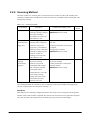
2.2.2. Scanning Method
The laser scanner has “scanning state” (emits laser beam to read a bar code) and “standby state”
(scanning is halted and in standby state). These two states are controlled to start scanning bar code
and stop the scanning.
Table. 2.22 Scanning methods
Scan method
Single scan
Continuous scan
(controlled with
trigger key)
Continuous
scanning
(controlled by
program)
Description
Conditions for scanning to end
Press the trigger key to start
scanning. Scanning is stopped
when either scanning is
succeeded or one of the scan
end conditions is met.
Press the trigger key to start
scanning, and scanning will
continue as long as the
trigger key is pressed down.
Scanning will stop when either
scanning is completed for just
preset no. of times for
scanning or one of the scan
end conditions is met.
Scanner library functions are
used to start and stop
scanning. The previous
scanning data and scanning
data overlapped with other
scanning data will be
disregarded. Also, to save the
power during scanning,
emitting laser beam will be
turned off between laser
emissions. (see note)
Timeout time has elapsed.
OBRClose function is called.
Timeout
Yes/No
Yes
Timeout time has elapsed after scanning
a bar code.
Scanning for the number of preset times
is complete.
The trigger key is released.
OBRClose function is called.
Yes
Timeout time has elapsed after scanning
the precious scanning.
Scanning end function is called while
scanning continues.
OBRClose function is called.
Yes
Note:
The scanning method set as default is with “Continuous scanning (controlled with trigger key)”
and “No. of preset times for continuous scanning = 1”.
Step Scan
This method is for scanning a designated number of bar codes. Once scanning for the designated
number of bar codes has been completed, the scanner will close and not scan again until reopened.
Also, the same bar codes that have been scanned previously cannot be scanned again.
34
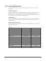
2.2.3. Scanning Parameters
Conditions that allow scanning a symbology in specific modes can be set for each readable
symbology.
Readable Symbology
Bar code symbologies that are enabled or disabled for scanning can be specified. If only specific
symbologies are to be scanned, set “Enable” for scanning on these symbologies only and
“Disable” on the other symbologies. This will reduce decode processing time and lower the error
rate. The default is “Enable scanning on all the symbologies”.
Readable Digits
The no. of readable digits can be set for each symbology. If only specific no. of digits is to be
scanned, specify it for each readable symbology. This will reduce decode processing time and
lower the error rate.
Enable or Disable Check Digit
Check digit can be set to “Enable” or “Disable” for each readable symbology. Setting the check
digit will lower the error rate.
Table. 2.23
Symbology
EAN, JAN,UPC-A/B
EAN, JAN,UPC-A/B Addon
UPC-E
UPC-E Addon
Code39
NW-7
Interleaved 2of5
Industrial 2of5
Code93
Code128
MSI
IATA
RSS-14
RSS Limited
RSS Expanded
RSS-14 Stacked
RSS Expanded Stacked
Check Digit Calculation
Enable or Disable
Enable or Disable
Enable or Disable
Enable or Disable
Enable or Disable
Enable or Disable
Enable or Disable
Enable or Disable
Enable or Disable
Enable or Disable
Enable or Disable
Enable or Disable
Enable
Enable
Enable
Enable
Enable
35
Default
Enable
Enable
Enable
Enable
Disable
Disable
Enable
Enable
Enable
Enable
Enable
Disable
Enable
Enable
Enable
Enable
Enable
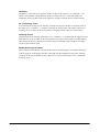
Validation
Validation is carried out for a specified number of times in the range of 1 to 9 (Default = 3) to
check if scanned data is valid, and then the data is output only if it is valid. The number of
validations can be set either at the control panel or using the Common Device Control Library.
No. of Scanning Times
In “Continuous Scanning” mode, scanning continues for the preset number of scanning times in
the range of 1 to 9 (Default = 1) and then it will stop in waiting mode. The number of times for
scanning can be set either at the control panel or using the Common Device Control Library.
Scanning Period
Valid time period of scanning in the range of 1 to 9 (Default = 3) seconds after the trigger key was
pressed down can be set either at the control panel or using the Common Device Control Library.
After the preset time has elapsed, the scanner will go into standby mode waiting for the trigger
key to be pressed down again.
Double Scanning Prevention
This is used to prevent double scanning of the same bar code during the “Continuous Scanning”
mode is being set. Scanning the same bar code again will be prohibited as long as the scanning
continues for the preset number of times. However, it can be scanned when a new “Continuous
Scanning” starts.
36
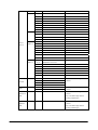
2.2.4. Scanning Output Format
Formats for outputting results of scanned bar codes can be set.
Table. 2.24 Output Formats
Symbology
Standard
No. of
Output Format
digits
JAN-13
13
FFMMMMMNNNNNCT
EAN-13
13
FFMMMMMNNNNNCT
Remark
T : Termination code
JAN-8
8
FFMMMNCT
EAN-8
8
FFMMMNCT
See Table 2.26 for meaning of the
JAN-13
15
FFMMMMMNNNNNCAAT
notations.
Excluding UPC-B, check digit (mod
addon+2
EAN-13
15
FFMMMMMNNNNNCAAT
18
FFMMMMMNNNNNCAAAAAT
18
FFMMMMMNNNNNCAAAAAT
10
FFMMMMNCAAT
10
FFMMMMNCAAT
13
FFMMMMNCAAAAAT
13
FFMMMMNCAAAAAT
UPC-A
12
0SMMMMMNNNNNCT
UPC-B
12
0SMMMMMNNNNNNT
UPC-A
14
0SMMMMMNNNNNCAAT
14
0SMMMMMNNNNNNAAT
10) calculation is always performed
addon+2
JAN-13
addon+5
EAN-13
addon+5
JAN-8
addon+2
EAN-8
addon+2
JAN-8
addon+5
EAN-8
WPC
addon+5
addon+2
UPC-B
addon+2
UPC-A
(note 2)
17
0SMMMMMNNNNNCAAAAAT
17
0SMMMMMNNNNNNAAAAAT
addon+5
UPC-B
addon+5
(note 2)
UPC-A
12
SMMMMMNNNNNCT
UPC-A
14
SMMMMMNNNNNCAAT
17
SMMMMMNNNNNCAAAAAT
JAN-13
14
0FFMMMMMNNNNNCT
EAN-13
14
0FFMMMMMNNNNNCT
GTIN
JAN-8
14
0000000FFMMMNCT
GTIN
EAN-8
14
0000000FFMMMNCT
GTIN
addon+2
UPC-A
addon+5
Continue.
37
GTIN
UPC-A
14
UPC-E
(7),8
UPC-E
UPC-E
(note 1)
Code39
NW-7
00SMMMMMNNNNNCT
GTIN
0MMNNNMCT
Last M: 0 to 2
(7),8
0MMMNN3CT
(7),8
0MMMMN4CT
(7),8
0MMMMMNCT
Last N: 5 to 9
(6),7
MMNNNMCT
Last M: 0 to 2
(6),7
MMMNN3CT
(6),7
MMMMN4CT
(6),7
MMMMMNCT
Last N: 5 to 9
14
0000000MMNNNMCT
GTIN Last M: 0 to 2
14
0000000MMMNN3CT
GTIN
14
0000000MMMMN4CT
GTIN
14
0000000MMMMMNCT
GTIN Last N: 5 to 9
UPC-E
(9),10
0MMNNNMCAAT
Last M: 0 to 2
addon+2
(9),10
0MMMNN3CAAT
(9),10
0MMMMN4CAAT
(9),10
0MMMMMNCAAT
Last N: 5 to 9
(8),9
MMNNNMCAAT
Last M: 0 to 2
(8),9
MMMNN3CAAT
(8),9
MMMMN4CAAT
(8),9
MMMMMNCAAT
Last N: 5 to 9
Last M: 0 to 2
UPC-E
(12),13
0MMNNNMCAAAAAT
addon+5
(12),13
0MMMNN3CAAAAAT
(12),13
0MMMMN4CAAAAAT
(12),13
0MMMMMNCAAAAAT
Last N: 5 to 9
(11),12
MMNNNMCAAAAAT
Last M: 0 to 2
(11),12
MMMNN3CAAAAAT
(11),12
MMMMN4CAAAAAT
(11),12
MMMMMNCAAAAAT
Last N: 5 to 9
3 to Max
SBBB -------- BBCST
See Table 2.27 for meaning of the
3 to Max
SAAA ------- AACST
notations
1 to Max
BBB ------- BBCT
1 to Max
AAA ------ AACT
3 to Max
SDDD ------- DDDST
See Table 2.28 for meaning of the
1 to Max
DDD ------- DDDT
notations
2 to Max
DDD ------- DDDCT
See Table 2.29 for meaning of the
Interleaved
notations
2of5
Only even number digits used for
scanning readable digits.
2 to Max
DDD ------ DDDCT
See Table 2.30 for meaning of the
Industrial
notations
2of5
Only even number digits used for
scanning readable digits.
Continue.
38
1 to Max
Code93
See Table 2.31 for meaning of the
notations
Code128
Code128
MSI
EAN128
1 to Max
AAA ------ AAAT
1 to Max
SBBB ----- BBCST
See Table 2.32 for meaning of the
1 to Max
AAA ------- AAAT
notations
1 to Max
SBBB ------ BBCST
See Table 2.33 for meaning of the
1 to Max
FAAA ------ AAAT
notations.
1to Max
GAAA ------ AAAT
1 to Max
DDD ------ DDCCT
See Table 2.34 for meaning of the
notations.
1 to Max
IATA
RSS-14
RSS
DDDDDDDDDD --------- CT
See Table 2.35 for meaning of the
PADDDDDDDDDDDDDDCT
notations
16
01DDDDDDDDDDDDDCT
See Table 2.36 for meaning of the
14
DDDDDDDDDDDDDCT
notations.
16
01DDDDDDDDDDDDDCT
See Table 2.37 for meaning of the
14
Limited
RSS
Expanded
RSS-14
Stacked
RSS
Expanded
Stacked
AAA ------ AAAT
DDDDDDDDDDDDDCT
notations.
1 to74
DD ---- DDDT
See Table 2.38 for meaning of the
1 to 41
16
14
AA ---- AAAT
notations.
01DDDDDDDDDDDDDCT
See Table 2.36 for meaning of the
DDDDDDDDDDDDDCT
notations.
1 to74
DD ---- DDDT
See Table 2.38 for meaning of the
1 to 41
AA ---- AAAT
notations.
Notes:
“C” will not be appended to the output if the no. of scanning digits described in parentheses in the
table above is applicable.
Table. 2.25 WPC symbology
F
M
N
S
A
T
C
Country flag
Manufacturer code
Product code
Number system character
Addon data
Termination code
Check digit (mod 10)
Table. 2.26 Code39 symbology
A
B
C
ASCII conversion post data
ASCII conversion pre data
Check digit (mod 43). Becomes data if there is no check
digit
S
Start and stop characters
39
Table. 2.27 NW7 symbology
S
D
C
Start and stop characters (any of a, b, c, d)
Data
Check digit (mod 16). Becomes data if there is no check digit
Table. 2.28 Interleaved 2of5 symbology
D
C
Data
Check digit (mod 10). Becomes data if there is no check digit
Table. 2.29 Industrial 2of5 symbology
D
C
Data
Check digit (mod 10). Becomes data if there is no check digit
Table. 2.30 Code39 symbology
A
B
C
ASCII conversion post data
ASCII conversion pre data
Check digit (mod 47). Becomes data if there is no check digit
S
Start and stop characters
Table. 2.31 Code128 symbology
A
B
ASCII conversion post data
ASCII conversion pre data
Table. 2.32 EAN128 symbology
C
S
F
G
Check digit (mod 47)
Start and stop characters
Code ID (only “]C1”, EAN128)
GS (only 1Dh, EAN128)
Table. 2.33 MSI symbology
D
C
Data
Check digit (mod 10, mod 11). Becomes data when there is no check
digit (note)
Table. 2.34 IATA symbology
D
C
P
A
Data
Check digit (IATA). Becomes data when there is no check digit
Coupon No
Airline No
Table. 2.35 RSS-14 symbology
D
C
Numeric data
Check digit (mod 10)
40
Table. 2.36 RSS Limited symbology
D
C
Numeric data
Check digit (mod 10)
Table. 2.37 RSS Expanded symbology
D
A
Numeric data
Alphabet data
Termination Codes
Select one of the following five termination codes to attach to the end of decoded data.
- CR
- LF
- CR+LF
- TAB
- No termination code (Default)
41
Output Buffer
The scanner scans a bar code and outputs the scanned data using one of the following methods
described in the table below.
Table. 2.38
Output Method
OBR buffer output
(see note)
Key message output
Clipboard output
Keyboard output
Description
- Scanned data is output to memory in the laser scanner driver.
- Scanned data already output to the memory can be captured using the
Common Device Control Library.
- Scanned data can be output with the window message to the specified
window handle.
- The window handle is specified using the Common Device Control
Library.
- Scanned result is copied to the clipboard and then output to the edit
control focused by caret.
- Scanned result is output as a keyboard event to the edit control focused
by caret.
Note:
OBR buffer Output
When a barcode is scanned, the decoded data including the symbology and data size are stored to
the memory in the laser scanner driver. This output method has the following features.
• Can capture the bar code symbology and data size.
• Can capture the data at any timing the user prefers.
• One piece of data can be a maximum of 98 characters long and up to nine labels can be stored
in the memory. If any new data scanned after exceeding over nine labels stored already in the
memory will be disregarded.
Conditions for Terminating Scanning
Scanning will be terminated when any of the following conditions is met.
• Scanning is succeeded.
• Preset timeout period has elapsed.
• OBR buffer becomes a full.
• An abnormal condition is detected in the scan module.
Scan Completion Notification
When scanning is completed, a notification is issued to the application using one of the methods
described in the table below. Each notification method can be set to “Enable” or “Disable”. The
default is “Notification with window message”.
Table. 2.39
Method
Window message
Event
None
Description
A window message is issued to the specified window handle. Also, the conditions for
scanning completion can be fetched by referring to wParam parameter of the window
message.
A predefined event in the registry is issued. The conditions of scanning completion can
be fetched using the Common Device Control Library.
No message or event is issued when scanning is complete.
42
Event Name
The predefined event name which is issued for event notification can be changed in the registry
described below. If there is no value set in the registry, the default event name,
OBRScanningEvent, will be used.
[HKEY_LOCAL_MACHINE\Drivers\CASIO\Laser]
Table. 2.40
Key Name
EventName
Setting Value
sz: Any name
Capturing Event Factors
When a notification for scanning completion is issued with “Event”, factors which made the
scanning succeeded are automatically recorded. The recorded factors are also fetched using the
Common Device Control Library.
43
Setting Specific Operation Unique to Code128 Symbology
The terminal supports specific operations unique to the Code128 symbology that are initiated
when certain conditions are met at a time of scanning a symbol of the Code128 symbology.
Table. 2.41
Symbology
Code128
Condition
At time of scanning a symbol of Code128
that includes the FNC2 function character.
At time of scanning a symbol of Code128
symbology that includes the FNC4
function character(s).
Performance
Scanned symbol data including the FNC2
function character is temporarily stored in the
scanner until when a next symbol is scanned.
The stored data is automatically added at the
forefront of the subsequent scanned symbol data
to be output. (See note below.)
The value “128” is added automatically to a data
character in ASCII of scanned symbol located
next to the FNC4 function character. If two
sequentially laid FNC4 function characters in a
symbol are scanned, either other group of two
sequentially laid FNC4 function characters
within the same symbol are read, or “128” is
added automatically to each subsequent ASCII
character data laid next to the two FNC4
function characters until the last.
Notes:
The size of combined symbol data including the FNC2 function character is limited to 98
characters (maximum). If the size of any combined symbol data exceeds the maximum number of
characters, the previous combined symbol data that have been scanned right before the exceeded
combined symbol data are output.
44
2.2.5. Scan Result Notification
When scanning a bar code is completed, a notification about the scanning result can be indicated
to the user with either LED or buzzer or vibration. Each indication method can be set to “Enable”
or “Disable”.
Table. 2.42
Indication
method
LED
Buzzer
Vibrator
Setting
Mode 1
Mode 2
Mode 3
(disable)
Enable
Disable
Enable
Disable
When
succeeded
When failed
(see note 1)
ON in green
ON in green
None
None
ON in red
None
Scanning
interrupted
(Trigger key
released)
None
None
None
Scan
completion
sound
None
Vibrates
None
None
None
Warning sound
Enable
None
None
None
None
None
None
None
None
None
Disable
OBR buffer
full
(see note 2)
Default
ON in green
ON in green
None
Mode 1
Notes:
1. Scanning will fail when one of the errors occurs.
- A bar code with the number of digits which exceeds over the specified range is scanned.
- Check digit calculation error occurs.
- Full ASCII conversion error occurs in scanning bar code of Code39 symbology or Code128
symbology.
2. During the “OBR buffer output” method has been set as scanned data output method, this
condition occurs if scanning takes place while nine labels worth of data are stored already in
the memory buffer.
45
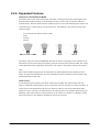
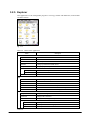
2.2.6. Expanded Features
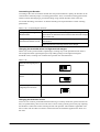
Control on Laser Emission Width
If the laser emits on bar codes located near each other, scanning may fail. By narrowing the laser
beam emission width, scanning can be focused onto only one bar code, not onto the other one
located near by. The laser beam emission width can be set to one of the following four modes. The
Common Device Control Library can be used to set it. The default is “No control on laser beam
emission width”.
-
No control on laser beam emission width
Wide
Normal
Narrow
No laser
width control
照射幅制御なし
Wide
幅広
Normal
幅中
Narrow
幅狭
The setting values are stored in EEPROM, and read out at time of resetting. Laser calibration (see
note below) can be used to adjust each setting value for the laser beam emission width. The setting
values adjusted must be registered in the registry. The values in the registry will have the priority.
Note:
Each scanner module integrated in the terminal has an individual performance difference from
others. To minimize this difference, the laser calibration must be executed on each terminal using
a dedicated reference bar code.
Laser Focus
If scanning takes place with the laser beam emitted onto multiple bar codes located near each
other, it is difficult to distinguish by the user which bar code was scanned. In such the condition, if
a laser beam can be emitted focusing only one the user wishes to scan and a notification about
which bar code is scanned is issued to the user, the scanning can be succeeded without having any
difficulty. The Common Device Control Library can be used to set “Enable” or “Disable” for this
laser focus function. The default is “Disable the laser focus function”.
46
Power ON with Trigger Key
If the Trigger key has been set to “Enable turning on the power with Trigger key”, the power can
be turned on (while the power was being turned off) when it is pressed. This function allows the
user to achieve multiple operations with only one action, turn on the power → press the Trigger
key → scan a bar code. This feature is a perfect idea when the user wishes to resume scanning
after the power has been turned off. The default is “Disable turning on the power with Trigger
key”.
Setting Trigger Key
Enter key, 4-way cursor key, side trigger key, grip trigger key (option) and center trigger key on
the front of the terminal can be set as the Trigger key. The default is only both left and right side
keys are set as the Trigger key.
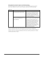
Noise Filter
If the background of a bar code is white color, a noise tends to be generated easily during
scanning causing the error rate to increase. To reduce such the noise, the noise filter function is
available with the terminal. Two methods are available to set the function operable.
Table. 2.43
Filter
Software
noise filter
ASIC noise
filter
Description
A software process removes noise. In
determining the blank at the leading edge of the
barcode, if there is a bar width smaller than a
certain value, it will be bonded to the fore and
aft data, the noise eliminated and the
determination made. Also, the time from scan
start to “enable” of software filter can be set.
Setting range: 1 to 8 seconds, Default : 3
seconds
Removes noise using the ASIC process. If there
is a bar width smaller than a certain value, it
will be bonded to the fore and aft data, and the
noise eliminated. This is normally effective in
preventing DMA overrun.
Merit
Effective when
scanning leading
edge blank of bar
code using laser
module noted for
easily picking up
noise.
Demerit
If initial bar is
extremely thin, it
will be determined
as noise and
eliminated, which
may mean that the
bar code cannot be
scanned.
---
---
Notes:
• Only the ASIC noise filter has been set enabled as default.
• The software noise filter is not required by the DT-X7 series.
47
Setting Gain
The laser module gain setting can be switched. Switching this setting enhances scanning
performance particularly for a bar code located far away from the terminal and a bar code printed
in high-resolution.
Operation Setting Information File
The various setting values can be stored in a file and resumed. The setting file storage location and
name are “\FlashDisk\System Settings\OBRDRV.ini”. If there is no such the setting file, the
default values are used to initiate the scanning.
Dual Decoder System
The dual decoder system initially decodes a scanned bar code data using the standard decoder, but
if decoding fails, it will use the following additional decoder to scan the same bar code. This dual
decoders system supports the bar code symbologies listed below.
- Code39
- Code128
- EAN
With the decoding system used for the previous CASIO handheld terminals, decoding is processed
with a mean value of one module adding bar thickness of each black bar and white bar for one
character when performing binaryzation or quardruplzation of bar thickness. However, this
method does not accurately decode a bar code if it is formed with unbalanced bar thickness
between white bars and black bars.
The dual decoder system can solve it by calculating separately each mean value of black bars and
white bars for such a bar code with unbalanced thickness of white and black bars by changing the
threshold level of decoding.
48
Customizing the Decoder
According to the scan environment and the bar code printed material’s quality, the decoder can be
customized to efficiently improve scanning performance. First, to maintain scanning performance
with the normal decoding logic, perform decoding using with the decoder and if it does not
succeed the decoding, customize it so that the decoding can be performed for a better scanning
performance.
Table. 2.44 Customizing the elements
Element
Change margin of the right/left
threshold values
Change of compensation values
of the thickness/thinness of a bar.
Description
Used to change the threshold values of right and left side marginal
spaces which are allocated for areas colored in white on the left and right
sides of a bar code.
Used to thicken or thin each bar of bar code for a specified value and
then decode it.
Value for thickening or thinning each bar can be changed.
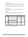
Changing the threshold values for Right and Left margins
When a bar code is printed inside of quadrangle, scanning may not be possible because there is
not enough left and/or right marginal space. By making change on the right/left marginal
threshold values, scanning a bar code becomes possible. See the table below.
Table. 2.45
When the left marginal space is
narrow.
When the right marginal space is
narrow.
When both right and left
marginal spaces are narrow.
Changing the thickness of bars
If bars of a bar code are printed thick because blurring or scratchy white bars (spaces between two
bars) are printed thinly, the bar ratio will not be correct causing scanning incorrectly. By adjusting
the thickness of these bars makes scanning the bar code possible. This method is applicable if all
bars of a bar code are either too thick or too thin because the method is applied to the whole of a
bar code.
49
2.2.7. Power Control
In order to save the power, the power will not be supplied to the laser scan module and the ASIC
module for laser beam control during the laser beam is not irradiating. It will be supplied to these
modules when the laser beam is to be irradiated, and turned off again when the laser beam is not
irradiated.
50
2.3. USB
2.3.1. Basic Specifications
Switching USB
• Switches between USB Client (USB Function) and USB Host.
• Switching between USB Client (USB Function) and USB Host is executed by a signal from
the cradle. This cannot be performed in application.
• Switching is not possible while a USB device is connected to the cradle and the terminal is
recognizing the USB device. Switching can be performed once the USB device is
disconnected.
• USBIsHost API function can be used to capture the current USB Client (USB
Function)/Host status.
USB Client (USB Function)
• Supports the USB 1.1 full speed.
• Communicates with “wceusbsh.dll” on PC side.
• Communication with PC can be established using ActiveSync.
• Communication with PC can be established using FLCE/LMWIN (ActiveSync must be
disabled.)
USB Host
• Supports the USB 1.1 full speed.
• Supports USB-MODEM/USB-LAN.
• USB device is disconnected when the terminal is suspended.
• Does not support WakeOn Ring/WakeOn LAN.
• Does not support communication via USB HUB.
USB-MODEM
• Supports the USB Communication Class (CDC: ACM).
• Communication with modem via virtual COM port can be established.
• Dial up via USB modem can be possible by selecting USB modem at the setting of connection
under WindowsCE.
USB-LAN
• Supports “SOHO-USBNET/100+”.
• Can be connected to network via the TCP/IP protocol.
51
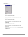
2.3.2. COM Port
COM ports used with USB are as follows.
Table. 2.46
USB Function
USB-MODEM
COM2
COM5
2.3.3. Product ID
USB product ID is as follows.
Table. 2.47
USB Client
0x3303
52
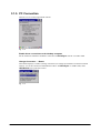
2.4. IrDA
2.4.1. Communication Speeds
The IrDA supports the following physical communication speeds.
Table. 2.48
Via
IrDA protocol
RAW IR
SIR
9600, 19.2K, 38.4K, 57.6K, 115.2K bps
9600, 19.2K, 38.4K, 57.6K, 115.2K bps
FIR
4M bps
-
Notes:
• A speed of communication via IrDA protocol is automatically determined by negotiation with
the partner device.
• The maximum communication speed supported commonly by both parties (the terminal and
the partner device) will be determined as communication speed.
• Communication speed cannot be set in application.
2.4.2. COM Port
COM ports used with IrDA are as follows.
Table. 2.49
IrDA protocol
RAW IR
COM3
COM4
53
2.5. Bluetooth
2.5.1. Basic Functions
Master
Establishes a connection with Bluetooth equipment in slave mode waiting for connection with the
master.
Slave
Becomes in waiting mode for communication initiated by the master.
Security, Encryption
Performs security (PassKey exchange) and encryption as laid down in the Bluetooth standard.
AFH
Automatically or manually limits and controls radio wave frequency band to be employed in
Bluetooth communication.
Fast Connection
This is to convert radio frequency for Bluetooth communication into transmission pattern which
allows connection establishment quickly.
WakeOn Bluetooth
This function establishes communication with a Bluetooth equipment that is being in suspended
mode and resumes the communication operation with that partner Bluetooth equipment.
54
2.5.2. Communication Profiles
The following are supported Bluetooth profiles.
Table. 2.50
Function
GAP (General Accessible Profile)
SDP (Service Discovery Profile)
Serial Profile (Client)
Serial Profile (Server)
DUN (Dial-Up Network)
PAN (Personal Area Network)
OBEX Object Push Profile
File Transfer Profile
Purpose
Used in the substructure segment of Bluetooth communications such
as device discovery, link establishment and security.
Used to search for currently usable services provided by the partner
Bluetooth equipment.
In Bluetooth serial communication, this is used for connection to other
Bluetooth equipment.
In Bluetooth serial communication, this is used for acceptance of
connection request from other Bluetooth equipment.
This is used in dial up communication via Bluetooth mobile phone.
This is used in network communication via Bluetooth PAN
Access-Point.
This is used as easy file send/receive.
This is used as file send/receive regulated by the Bluetooth standard.
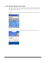
Bluetooth communication application and communication method as well as profile relationships
are as follows.
Table. 2.51
Partner Bluetooth Equipment
Communication Application
Profile
Bluetooth mobile phone, Bluetooth modem, etc.
Dial up
DUN
Bluetooth access point (PAN Profile support)
Bluetooth printer
PC for Bluetooth + Active Sync
Between handheld terminals, PDA that supports
Bluetooth, PC that supports Bluetooth, etc.
LAN connection
Printing to printer
Connection with host PC
File transfer between
Bluetooth equipment
PAN
Serial Profile
Serial Profile
OBEX Object Push
File Transfer
55
2.5.3. Security
This feature supports security functions laid down in the Bluetooth standard. The Bluetooth
security is divided into authentication and encryption. These are realized by the use of PassKey
(otherwise known as PIN code). PassKey is a shared (common) authentication key used when
forming a connection and trust relationship (bonding) with Bluetooth equipment. A maximum of
16 characters (in ASCII code) can be used, but there may be limitations on the no. of digits and
usable characters due to the specifications of partner Bluetooth equipment. Also PassKey input
must be done within 30 seconds from a time when PassKey input request is generated. Note that
PassKey input is not required once “device trust” has been established with Bluetooth equipment
in previous connection. However, the partner Bluetooth equipment must have also the trust
relationship in memory.
Encryption is executed using a link key generated after PassKey exchange and a cipher key
generated from a 128-bit random number. Here, the partner Bluetooth equipment also must
support the encryption. PassKey exchange is required for Bluetooth connection when encryption
is set enabled.
2.5.4. COM Port
The following are the COM ports used with Bluetooth.
Table. 2.52
Serial Profile (Client)
Serial Profile (Server)
DUN (Dial-Up Network)
COM6
COM7
BTP1
Simultaneous Use of multiple Bluetooth COM Ports
Multiple Bluetooth COM ports cannot be opened simultaneously and used.
56
2.5.5. Communication Procedures
The following are the basic procedures for using Bluetooth to communicate.
Initializing Bluetooth
This function initializes the Bluetooth using either the Bluetooth tool or the Common Device
Control Library. It will turn ON the power to the Bluetooth module integrated in the terminal and
initialize the Bluetooth protocol stack.
1. Searching a Bluetooth equipment
Searches a Bluetooth equipment using the Bluetooth tool or the Common Device Control
Library. This sends out an equipment search radio wave and captures information from
Bluetooth equipment operable in the vicinity.
2. Capturing service information
Captures service information using either the Bluetooth tool or the Common Device Control
Library. This captures the current usable service (profile) information of the partner Bluetooth
equipment.
3. Security authentication with PassKey exchange
The partner Bluetooth equipment may request a PassKey at a time of capturing service
information and establishing Bluetooth connection. In case the Bluetooth tool is used, the
same PassKey is input for both Bluetooth equipments (the terminal and the partner Bluetooth
equipment) when a dialogue window appears requesting PassKey input. In case the Common
Device Control Library is used, the PassKey must be set in advance by executing the relative
functions for setting PassKey.
4. Establishing the connection
Establishes a Bluetooth connection using either the Bluetooth tool or the Common Device
Control Library. After the connection has been established, communication in Bluetooth can
be continued using the selected profile until the connection is terminated.
5. Terminating the connection
Terminates the connection using either the Bluetooth tool or the Common Device Control
Library.
6. Closing the Bluetooth
Closes the communication via Bluetooth either by ending use of the Bluetooth tool or by
executing relative functions of the Common Device Control Library for closing the
communication, and then turns off the power to the integrated Bluetooth module.
57
2.5.6. Communication Procedures by Profile
While Bluetooth communication takes place, there is a chance that the communication link may
be interrupted due to the air condition, so the retry process is always recommended in application
to verify the communication. In general, it is recommended also that the retry process should be
carried out in any wireless communication including WLAN if it takes place within the vicinity by
other equipment using the same frequency band (“ISM” band) such as microwave oven.
Serial Profile
Bluetooth connection can be managed using either the Bluetooth tool or the Common Device
Control Library.
DUN (Dial-Up Network)
Bluetooth connection can be managed using either the Bluetooth tool or the Common Device
Control Library. The communication will take place with RAS setting using “BTP1”. After the
connection has been established, communication via the TCP/IP protocol is possible.
PAN (Personal Area Network)
Once connection to Access-Point has been established using the Bluetooth tool, communication
via the TCP/IP protocol is possible.
OBEX (Object Push Profile)
File transmission or reception using the Bluetooth tool is possible.
FTP (File Transfer Profile)
File transmission or reception using the Bluetooth tool is possible.
58
2.5.7. Process after Communication Interruption
With Bluetooth communication, there is a chance that the communication link may be interrupted
due to the radio wave condition in air. An error occurred during the communication is detected by
executing WriteFile API function or ReadFile API function, etc.
In case where the communication is interrupted, carry out the normal Bluetooth interruption
process using the Bluetooth tool or in application and then retry to establish the same connection
for communication. If the normal Bluetooth interruption process is not made, unconformity in the
Bluetooth stack will occur so that the lower layer is disconnected whereas the upper layer is still
being connected causing the retry of establishing the connection is not possible.
2.5.8. Processing During Suspend and Resume
When the terminal goes into suspend mode while Bluetooth is being used, the power to the
Bluetooth module integrated in the terminal will be automatically turned off. After that, when the
terminal resumes operation mode, the power to the Bluetooth module also will be turned on
automatically. Once the power is turned off, all the parameters related to Bluetooth
communication return to their initial states. These parameters must be set again in the Bluetooth
module by initializing the Bluetooth stack. If the Bluetooth tool is used, it will automatically
detect “suspend” and “resume” modes, and automatically initialize the Bluetooth stack. Note,
however, that if WakeOn Bluetooth function has been set enabled, the power to the Bluetooth
module will remain on even if suspend is executed. This will not initialize the Bluetooth stack.
2.5.9. Setting SR Mode Parameter
When executing Bluetooth communication, the connection will be established by transmitting
radio waves by master Bluetooth equipment to slave Bluetooth equipment. Note that it may take
time sometime to make the establishment depending on a type of the partner Bluetooth equipment.
Here, by altering the SR mode parameter (used in Bluetooth connection), radio waves sent out
when the master Bluetooth equipment makes the establishment will change, and may reduce the
time required to establish the communication. The SR mode parameter can be set in the following
registry.
[HKEY_CURRENT_USER\SOFTWARE\RXBT\HCI]
Table. 2.53
Key
DEFAULT_PAGE_SCAN_REP_MODE
Setting Value
dword: 0 or 1 or 2
Meaning
0:R0, 1:R1, 2:R2
Notes:
• Change the SR mode parameter prior to Bluetooth connection.
• Even if the SR mode parameter is changed, the time required to establish connection with the
partner Bluetooth equipment may not be reduced.
59
2.5.10. WakeOn Bluetooth Function
The terminal in suspend mode can be put into resume mode by communication initiated by the
partner Bluetooth equipment. The following is an example of putting the terminal into resume
mode by Bluetooth dial up communication using a Bluetooth mobile phone.
1. Set the information for connecting with other party’s Bluetooth equipment in advance in the
terminal (DT-X7) and Bluetooth mobile phone.
2. Set respectively the terminal in suspend mode and Bluetooth mobile phone in waiting mode to
receive a mail from server.
3. Bluetooth mobile phone receives task mail from the server. The server disconnects after
sending out the mail.
4. Bluetooth mobile phone activates as master and makes a connection with the terminal.
5. The terminal resumes operation mode and completes Bluetooth connection, and then receives
the task mail from the Bluetooth mobile phone.
6. After receiving the task mail, the terminal disconnects the Bluetooth connection.
7. Application in the terminal will execute Bluetooth connection to the Bluetooth mobile phone
using Dial Up Profile.
8. The terminal will execute dial up to the server via the Bluetooth mobile phone.
9. The application in the terminal will execute sending/receiving data to/from the server after dial
up completes.
10. After sending/receiving data completes, dial up connection will be disconnected by the
terminal. The Bluetooth connection will be disconnected as well.
60
2.6. WLAN
The IEEE802.11b and IEEE802.11g WLAN is operable on the models, DT-X7M10R. The
IEEE802.11b and IEEE802.11g standards utilize unlicensed 2.4 GHz ISM (Industry, Science, and
Medical) frequency band, which is used for close range wireless communication.
Device Name
With terminal, the device name used to capture data about the WLAN driver with
DeviceIoControl function is “PY55BG1”.
2.6.1. Basic Specifications
Roaming
This function automatically switches Access-Point in environment where two or more
Access-Points with identical SSID code exist.
Power Saving
This saves the power by automatically turning off the power to the integrated WLAN module in
the terminal when communicating does not take place.
AdHoc
This operation mode provides a direct communication between wireless equipments without the
use of Access-Point. Note, however, that the AdHoc mode is not recommended because
connection problem may occur.
WEP
This is an encryption function that uses RC4 method for safe communication. It supports 40-bit
(64-bit)/104-bit (128-bit).
TKIP
TKIP is supported to combat the weakness with WEP encryption.
802.1x Security
This can strengthen authentication and establish a safer WLAN. Usually, this is interlinked with
TKIP. It supports PEAP-EA, P-MS-CHAP-V2, and EAP-TLS.
61
2.6.2. Expanded Features
Power ON/OFF Control
The power to the integrated WLAN module can be controlled in application. Turning off the
power when the WLAN module is not in use can save power, prevent line congestion and allow
the on-board use in aircraft.
Operation Configuration File
The operation configuration file can be used to set each default value of the WLAN settings.
Resume Operation
After the terminal went into suspend mode and then returned in resume mode during wireless
operation, this will automatically establish connection again with the Access-Point to enable
continuous wireless communication.
Out of Range, In Range
This will automatically establish connection again with the Access-Point to enable continuous
wireless communication when the terminal returns within the range from out side of the range of
the Access-Point during wireless operation. This will automatically reconnect to the Access-Point
if connection establishment with the Access-Point cannot be maintained due to noise or
interference, or roaming is not possible for some reason.
62
2.6.3. Roaming
This feature automatically switches the Access-Point located in environment where two or more
Access-Points with the identical SSID code exist.
1. Searches for Access-Points that can be communicated with the terminal, and lists up radio
wave status of each Access-Point.
2. Compares radio wave status of the currently connected Access-Point with those for the listed
Access-Points.
3. If the comparison proves that one of the listed Access-Points has a better radio wave status than
the one currently being connected with the terminal, the terminal will make a request of
roaming to that Access-Point.
4. If roaming permission comes from the Access-Point to the terminal, the roaming will complete.
Note that if the roaming fails, the connection establishment will be disconnected and then
connected again.
Notes:
• In some cases, the Access-Point may request the terminal for forcible roaming or reconnection
with other Access-Point.
• If connection establishment of the Access-Point being connected with the terminal is
terminated due to some reasons such as turning off the power on the Access-Point, the
terminal may be forced to make a connection with other Access-Point.
• If it takes time for Access-Point to correspond for roaming request made by the terminal, the
reconnection process may be initiated.
• If DeAuthentication or DisAssociation message issued by the Access-Point that is being
connected with the terminal after roaming, the connection establishment between the
Access-Point and the terminal may be interrupted temporarily and then connected again.
63
2.6.4. Zeroconfig
This feature coordinates with the module firmware and the WLAN driver to perform some of the
WLAN link management and the Network management.
1. If multiple SSIDs are registered as prioritized connections, attempt to establish connection will
be performed to each registered SSID. In this case, the interval of time period for reconnecting
will become prolonged. If the reconnection time is considered to be as importance, register one
SSID only as prioritized connection.
2. Reconnection loop process will initiate when a disconnection notification is issued by the
module, or when Association fails.
3. The reconnection loop process will end when the terminal succeeds connection establishment
with one of the multiple SSIDs registered as prioritized connections.
Connection Process
Zeroconfig will instruct the WLAN driver and the WLAN module to make connection when
finding an Access-Point registered in the prioritized SSID list. Each firmware of the driver and the
module both instructed initiates necessary process following the rules of IEEE802.11b and
IEEE802.11g standards to make connection with the Access-Point. If multiple SSIDs are
registered as prioritized connections in the prioritized SSID list, attempt to establish connection
with each SSID will be made.
Disconnection Process
In the following cases, the connection establishment with Access-Point will be disconnected.
Firmware in the WLAN module judges on the disconnection and the roaming process.
1. When the quality of radio wave in air deteriorates because of interference from other WLAN
equipment, noise, similar causes, or on-air communication by other WLN devices.
2. When the Access-Point locates far from the terminal, or when radio waves are weakened by
obstacles
3. When other Access-Point that can allow roaming to avoid the poor environment described in
the situations 1 and 2 above cannot be found.
Resume Process
The following processes are performed when the terminal goes into resume mode.
1.
2.
3.
4.
5.
6.
7.
Unloading the driver
Loading the driver
Initializing
Scanning Access-Point
Creating the Access-Point list
Establishing connection with Access-Point
Changing the Task tray icon
64
2.6.5. Channels
The factory set default channels is set to “1CH-13CH” (13 channels).
2.6.6. WLAN Setting with Configuration File
The configuration file can be used to set the default values for the WLAN settings. By loading the
configuration file into the terminal, settings required for WLAN operation can be easy.
• The configuration file is “\FlashDisk\System Settings\WLANCFG.ini”.
• If no configuration file is available, WLAN operation is initiated with the default settings.
Timing to Load the File
The timing for incorporating the configuration file is when a reset or a full reset is performed on
the terminal. When loading the configuration, if the file itself does not exist, its format is wrong,
or the file has been specified as “Disable configuration file”, the default settings will not be made
using the configuration file.
Creation Method
The WLAN settings made using Microsoft’s “WLAN setting” will not be reflected in the
configuration file.
65
File Format
File format of the configuration file is INI format with the specifications described below.
• The maximum size of the configuration file is 60Kbytes.
• A line starting with “;” is regarded as a comment. It is not regarded as a comment if it locates
in the middle of a line.
• The separator for KEY and VALUE is “=”. Space and tab, etc., also are included in KEY and
VALUE. If a space is inserted after “=” in “SSID=□tunami”, the SSID value is space +
tunami.
• The end of a line is CR or CR/LF.
• The maximum length of a line is 256bytes.
• Section name, KEY, and VALUE are case sensitive.
WLAN section
All WLAN settings are made here.
Table. 2.54
Key
WLANPOWER
POWERSAVE
WLANCFG
RoamingRSSILevel
RoamingAvailableTime
RoamingRSSISpan
BandConfig
Setting Value
Specify turning on or off the power to the WLAN module.
1: Power ON
0: Power OFF
Specify the WLAN power save setting.
1: Enable power save.
0: Disable the power save.
Specify “Enable or Disable” on the configuration file itself.
1: Enable the file.
0: Disable the file.
Specify the roaming threshold value in dBm.
Specify time period in second for starting roaming again.
Specify intensity difference in dBm for radio wave during roaming.
Specify communication speed
0: Only IEEE802.11b
1: Both IEEE802.11b and IEEE802.11g
66
TCIP section
This is for setting the integrated WLAN module’s IP address.
Table. 2.55
Key
DHCP
IPADDRESS
SUBNETMASK
DEFAULTGATEWAY
DNS1
DNS2
WINS1
WINS2
Setting Value
Specify “Enable/Disable” on the DHCP.
1: Enable DHCP.
0: Disable DHCP.
The following settings are disabled if “Enable” is specified.
Specify IP address.
Specify subnet mask.
Specify default gateway.
Specify primary DNS server address.
Specify secondary DNS server address.
Specify primary WINS server address.
Specify secondary WINS server address.
Example of Configuration File
[WLAN]
WLANPOWER=1
POWERSAVE=1
WLANCFG=1
BandConfig=1
RoamingRSSILevel=-78
RoamingAvailableTime=15
RoamingRSSISpan=1
RoamingAvailableTime=60
BandConfig=1
MAX_SCAN_TIME=105
SCAN_CHANNELS=123456789ABCDE
WLAN_CFGTOOL=WLANCONFIG
[STATIC]
SSID=tunamiAP1200imai
ADHOC=0
SECURITY=WEP=1
AUTH=OPEN
WEP_OPEN_KEYINDEX=01
KEYDATA= 5C1E1455A2D504920483C59EA19AC2AB3F12821273BD2A17A9BE
WEP_OPEN_KEY=516DFEC900486137CB9D8C82993F184B508A916F5B5E733A0159
Continue.
67
[TCPIP]
DHCP=0
IPADDRESS=192.168.1.100
DEFAULTGATEWAY=192.168.1.100
SUBNETMASK=255.255.255.0
DNS1=192.168.1.101
DNS1=192.168.1.102
WINS1=192.168.1.103
WINS2=192.168.1.104
68
2.7. Power Control
2.7.1. Low Voltage Monitoring
Four levels of the low voltage monitor control are provided for the terminal.
Table. 2.56
Level
VDET1
Description
Warning against low
voltage of the battery pack
VDET2
Turning off the power due
to low voltage of the
battery pack
Emergency turning off the
power due to low voltage
of the battery pack
Turning off the power due
to low voltage of card
VDET3
VDETCF
Action
Issues warning
message for low
voltage of the battery
pack
Turns off the power.
Next Startup
-
Resume (with warning at time of
startup)
Forces the terminal to
turn off the power.
Warm boot (with warning at time of
startup)
Turns off the power.
Resume (with warning at time of
startup)
Battery Pack
The following shows statuses and levels available for the battery pack.
Normally the battery status is checked once every five seconds. However, it will be performed
every second when the power management property is displayed. Taking last immediate ten data
of the power voltage from AD converter, its average is calculated to classify the status in three
levels, either “Almost exhausted (10 % of the capacity or less)”, or “Low (30 % of the capacity or
less)”, or “O.K. (30 % of the capacity or more)”. The level is 10 % of the capacity when VDET1
occurs.
Table. 2.57
Status/Level
Status
External
Level
Notation
External power
Recharge
Recharging
Normal
1
Main battery
O.K.
2
Low
3
Almost
exhausted
Description
Power by AC adaptor is being supplied, and charging the
battery pack is complete.
Power by AC adaptor is being supplied, and charging the
battery pack continues.
Power by the battery pack is being supplied.
The battery pack has been fully charged or has a sufficient
capacity.
The battery voltage level is half or less.
“VDET1” has been detected.
69
Memory Backup Battery
The following shows levels available for the memory backup battery.
Table. 2.58
Level
Notation
1
O.K.
2
Almost exhausted
Description
The memory backup battery has been fully charged or has a
sufficient capacity.
The memory backup battery is in abnormal state.(10%以下)
2.7.2. Power ON Factors
The followings are the power ON factors. These factors can be set enabled or disabled using the
Common Device Control Library.
• The Power key is pressed while the power is off.
• A time period set for the Alarm function has been elapsed.
• The terminal is mounted on the cradle while the power is being supplied by AC adaptor via
the cradle.
• Trigger key has been pressed.
• WakeOn call has been issued by the Bluetooth module.
• VDETI has occurred while the WakeOn function has been set enabled.
Power ON Disable Factors
Factors that do not allow turning on the power are as follows.
• When the battery pack’s voltage level is not sufficient enough to start up the terminal (VDET2
level or lower).
• The battery cover lock is open.
70
2.7.3. Power OFF Factors
The following are the power OFF factors.
• The Power key is pressed while the power is on.
• Neither key input, disk access, card access, nor communication is performed within a preset
time period.
• Output voltage from the battery pack is low (VDET2, VDET3) (see note).
• The battery cover lock is open.
• An excess of load on the CF card lowers voltage (VDETCF) (see note).
• Internal temperature in the terminal exceeds over 70 ºC.
Note:
Warning message will appear a next time when the power is turned on.
Power OFF Time
When either VDET2, BCVR, VDETCF or VDET3 occurs, the power will be turned off after the
respective time periods elapse.
Table. 2.59
VDET2
BCVR
VDETCF
VDET3
Turning off (resume OFF) the power after 200 milliseconds.
Forced to turn off the power after 500 milliseconds.
71
2.7.4. Power Saving
Idle
The power will be saved by putting the CPU into idle state when event standby status is detected
by either the terminal or an application running on the terminal. The peripheral devices are
running while the CPU is in the idle state.
APO (Auto Power OFF)
The power is automatically turned off when the state of no key input, no disk access, no card
access, or no communication, etc., is detected within a preset time period. Setting the APO
function enabled or disabled, or a time period to activate the function can be performed using the
Common Device Control Library.
Dimming and ABO (Auto Backlight OFF)
The backlight is automatically dimmed or turned off when a preset time period has elapsed if the
state of no key input, no disk access, no card access, or no communication, etc., is detected within
the period. Setting a time period before starting dimming and a time period before turning off the
backlight (Auto Backlight OFF), and setting “Enable or Disable” on the dimming and the Auto
Backlight OFF functions can be set using the Common Device Control Library.
CPU Clock Frequency Control
The CPU clock frequency is changed to one of the frequencies described in the following table
depending on the CPU load or user designation. It can be changed at the control panel or using the
Common Device Control Library. The default is “AUTO”.
Table. 2.60
POWERSAVE
NORMAL
TURBO
AUTO
104 MHz
208 MHz
520 MHz
Automatically changes frequency to 104, 208, 520 or 13 MHz depending on CPU load.
Virtual Power OFF/WLAN Standby
This is standby mode for WLAN operation. The Common Device Control Library is used in
application to turn off the LCD, keys and set the CPU frequency to “POWERSAVE” mode to
save the power. Other peripheral devices are running.
Table. 2.61
Display
KEY
APO
Turning off the power with the Power key
CPU clock frequency
OFF
Lock
Prohibit
Prohibit
POWERSAVE
72
2.7.5. CPU Power State Control
The following shows the power states operable on the terminal.
Table. 2.62
State
Discharge
RTC backup
SLEEP mode
RUN mode
POWERSAVE
NORMAL
TURBO
AUTO
IDLE mode
DeepIdle
Contents
State in that the battery pack has been discharged, and the super capacity has been
also discharged. Neither RAM nor RTC will be backed up.
State in that only the RTC is being backed up. RAM is not backed up.
State in that the power on the terminal is turned off, and peripheral devices are also
turned off. RTC and RAM are backed up.
State in that the terminal is running or application is running on the terminal.
The CPU is running at 104MHz.
The CPU is running at 208MHz.
The CPU is running at 520MHz.
The CPU is running at either 104, 208, 520, or 13MHz depending on the CPU load.
State in that the terminal or application is waiting for an event to occur.
If the CPU clock frequency has been set to “AUTO” mode, and the
backlight is turned off, the CPU runs at 13MHz (“DeepIdle” mode).
Note however that the CPU will be in ordinary “Idle” state, not DeepIdle
mode, if periodical accesses are made to the integrated WLAN card.
73
Discharge
Operating/Memory backup
battery insertion
Memory backup battery empty
RTC backup
SLEEP mode
Operating battery empty
Power ON
Power ON
Power OFF
WakeUp
VDET2/3
Battery Cover open
RUN mode
Mode
Turbo
Power save
Normal
NORMAL
TURBO
No activity
POWERSAVE
Interrupt
IDLE mode
DeepIdle
Fig. 2.6
74
2.7.6. Charging, Supplying the Power
The optional Dual Battery Charger (HA-F32DCHG) can be used to charge battery packs (two at a
time). Mounting the terminal on the USB Cradle (HA-F60IO) or on the Cradle-type Charger
(HA-F30CHG) or on the Ethernet Cradle (HA-F62IO) allows charging the battery pack installed
in the terminal and supplying the power to the terminal.
75
2.7.7. Temperature Control
If temperature rise is detected in the terminal when running at the highest clock frequency (under
such the condition that the CPU speed at “TURBO”, the integrated WLAN module in active mode,
etc.), a warning message stating that “An error occurs !! Original reference cannot be found”
appears and the power is turned off to protect the integrated devices in the terminal.
Fig. 2.10
Either turn off the power and leave the terminal unused for a while move it to a location where the
surrounding air temperature is cooler.
If power is turned off due to the temperature limit, a warning message stating “An error occurs !!
Original reference cannot be found” will appear when the power is turned on a next time.
Fig. 2.11
76
2.8. Security
2.8.1. Setting Password for Terminal
This is the password setting implemented in the WindowsCE OS. A password can be set at the
control panel.
2.8.2. Setting Password for Date and Time Properties
This is to enable setting a password for accessing the date and time setting in order to prevent the
user from changing the settings of the terminal. Use PASSTOOL located under Windows folder
to make the setting. Password registered will be saved in the FlashROM along with individual ID
setting, etc.
2.8.3. Setting Individual ID
Individual ID is written into a predetermined area in the FlashROM at time of shipping from the
factory. Distributor code (a code used to protect distributor developed software from illegal
copying by unauthorized party) is saved in other area different from the individual ID. The
individual ID incorporates the product code and serial number etc. and always becomes a unique
code different from other units. The Common Device Control Library can be used to read the
individual ID set on each unit of the terminal.
2.8.4. Setting Distributor ID
The individual ID and distributor ID can be used by the distributor and user to prevent illegal use
of application by unauthorized party at a time of installing or executing the illegally copied
application by checking these preset codes. The distributor code is saved in the FlashROM area,
and read using the Common Device Control Library.
77
3. Application
This chapter explains about applications available in the terminal. They are classified into several
groups described in the table below.
Table 3.1
Classification
Control Panel Applets
Application programs
Utilities
Host applications
Description
Start up the applets at the control panel. The applets are used to set the
parameters required for the terminal and integrated devices.
Start up applications by accessing the menus in order of Start → Program.
Operational screens of each application appear and then the related processes are
executed.
The utilities are executed as co-process or auxiliary program in user applications.
Application programs used by host PC.
78
3.1. Control Panel Applets
The control panel applets are programs that display each content of the various parameters for the
terminal itself and change the settings. The control panel applets are as follows.
Table 3.2
Applet
Bluetooth
Connection
WLAN Power (note)
CPU Speed
Error Reporting
PC Connection
USB connection
enabled
Remove Programs
Internet Options
Keyboard
System
Terminal Server
Client Licenses
Dialing
Network and Dial-up
Connections
Version Info
Vibrator
Password
Power
Buzzer
Volume & Sounds
Mouse
Laser Setting
Display
Screen Resolution
Storage Manager
Owner
Certificates
Regional Settings
Date/Time
Description
Executes connection establishment with Bluetooth device.
Sets up the powers for CF card and WLAN.
Sets up the CPU’s clock frequency.
Sets up error report.
Changes the desktop settings of connection with PC.
Checks USB connection status.
Deletes application program installed in the terminal.
Changes internet settings.
Changes the speed of key repeat input and the maximum
waiting time.
Displays system information and changes memory settings.
Displays authentication license for registered terminal
service client.
Changes telephony settings.
Connects the terminal to other PC, network or internet.
Displays the terminal version information.
Sets up the vibrator’s operation.
Changes owner password and security options.
Changes the power management options.
Sets up buzzer sound volume.
Sets up type and its sound volume.
Adjusts double click speed.
Changes the scanner settings.
Changes the desktop background.
Sets up the resolution setting.
Manages storage location and its disk partition.
Changes owner’s personal profile.
Displays and changes the terminal’s system and its digital
certificate.
Changes display methods of numeric value, currency, date
and time.
Changes settings for data, time and time zone.
Continue.
79
CASIO
Yes
MS
--
Yes
Yes
--Yes
--Yes
Yes
--
----
Yes
Yes
Yes
---
Yes
Yes
---
Yes
Yes
-Yes
--Yes
--Yes
-Yes
--
Yes
-Yes
Yes
-Yes
Yes
-Yes
-Yes
--
Yes
--
Yes
--
Yes
--
Yes
Input Panel
Brightness
WLAN Settings
Changes the current input method and options.
Changes the backlight brightness.
Sets up the WLAN’s operation.
Note:
DT-X7M10R and DT-X7M10R-CN models only
80
-Yes
Yes
Yes
---
3.1.1. Bluetooth Connection
This applet executes connection establishment with other Bluetooth device. For detailed
explanation on the Bluetooth settings, refer to the DT-X7 series Bluetooth Setting Manual
available separately.
Fig. 3.1
81
3.1.2. WLAN Power
This applet is to set up the settings for power to a CF card or the integrated WLAN module
(DT-X7M10R and DT-X7M10R-CN models only) and to display the detected status on the
power.
Fig. 3.2
CF/WLAN Power Enable Detected
Set up the checkbox enabled (see Fig. 3.2) to supply the power to the integrated WLAN module.
82
3.1.3. WLAN Settings
This applet is to set up the settings for WLAN connection.
CASIO WLAN Setting Tool
The tool of WLANConfig starts up by displaying the WLAN settings stored in the “ini” file if it
exists in the terminal, or the default WLAN settings if it does not exists, and then displays IP
Setting tab as shown in Fig. 3.3.
IP Setting Tab
Fig. 3.3
Basic Setting Tab
This tab sets up SSID and Security. Click the radio button of Authentication to enable “Open” for
WEP. Select either 128 bit radio button or 64 bit radio button for Key Length. For Key Index, up
to four kinds of key can be registered.
Fig. 3.4
83
Search Button
This button invokes the NetSearch utility.
Security, Authentication Fields
Select one of the three radio buttons in the Security field. By clicking the WPA radio button,
authentication in either PSK, EAP-PEAP or EAP-TLS can be set up. If PSK is selected in
Authentication, input a key in the Key field to register. See Fig. 3.5.
Fig. 3.5
If EAP-PEAP or EAP-TLS is selected, user name, domain validate server, etc. can be set up.
Fig. 3.6
84
WLAN Setting Tab
This tab sets up the basic WLAN settings such as power to the WLAN module, power save mode,
WLAN standard and the threshold level (RSSI level) of roaming.
Fig. 3.7
Detail Setting Tab
This tab sets up the detailed settings. It allows to set up which application, either “NetSearch” or
“NetUI”, to be used to set up for the display of WLAN condition. “NetUI” is a tool from
Microsoft. AdHoc connection, all security settings and a comment for the configuration file (“ini”
file) can also be set up. For Advance Setting and Version buttons, refer to the next page.
Fig. 3.8
85
Advance Setting Button
This button (see Fig. 3.8) displays a window of Advance Setting shown in Fig. 3.9. The
window sets up frequency channels from no. 1 to no. 14 used in WLAN operation and the detailed
settings for the roaming.
Fig. 3.9
Version Button
This button display the version information about the application currently running.
Fig. 3.10
86
If OK button in Fig. 3.10 is clicked, “Inifile Save Options” screen in Fig. 3.11 appears. This
screen is to save the settings you made on each tab of Basic Setting, IP Setting, WLAN
Setting, and Detail Setting of the WLANConfig tool. Cliking OK button in Fig. 3.11 will save
the settings made on the four tabs to the ini file, and then start up the terminal to run in WLAN
operation. Or, clicking Cancel button saves the settings to the ini file, but does not start up the
terminal. The settings will not become effect until when a reset on the terminal is performed a
next time.
Fig. 3.11
87
Wireless Information Tab (the tool from Microsoft)
This tab displays a list of networks (SSID codes) connectable to the terminal and the current
network being connected and the radio wave signal strength. See Fig. 3.12.
Fig. 3.12
Double click a network highlighted on the screen you wish to display the Wireless Property
screen.
Connect Button
This button displays the Wireless Property to set up the parameters required to connect the
terminal with the Access-Point.
Advanced... Button
This button displays Advanced Setting screen to set up the detailed settings for WLAN
connection.
Log... Button
This button displays operation logs for the WLAN operation.
88
Wireless Properties Screen
Fig. 3.13
Network name (SSID)
This field is to specify a network (SSID) name.
This is an ad hoc network
Set the checkbox enabled to communicate in AdHoc mode. Note, however, that the AdHoc mode
is not recommended because a communication difficulty may occur.
Encryption
Using the pull-down menu, set Encryption to either “Disabled” or “WEP”. When “WEP” is
selected, specify the appropriate items in the fields listed below and set the checkboxes enabled or
disabled as needed. See Fig. 3.13.
- Authentication
- Network key
- Key index
- The key is provided automatically
- Enable 802.1x authentication
- EAP type
89
Connection Setting Screen
IP Address Tab
Fig. 3.14
Obtain an IP address via DHCP
Set this radio button enabled if the DHCP server is used.
Specify an IP address
Set this radio button if an IP address is specified directly without using the DHCP server. In this
case, enter codes in each field of IP Address, Sub Net Mask and Default Gateway.
Name Servers Tab
This tab is to specify Primary DNS, Secondary DNS, Primary WINS and Secondary
WINS as required.
Fig. 3.15
90
Advanced Wireless Settings Screen
Fig. 3.16
Use Windows to configure a network
Enable (set to on) this checkbox if Windows is used to configure the network settings. In this case,
specify the appropriate items in the fields listed below and set the checkbox enabled or disabled as
needed. See Fig. 3.16.
- Preferred Networks
- Automatically connect to non-preferred networks
- Networks to access
91
3.1.4. CPU Speed
This applet is for setting the CPU operating mode.
Fig. 3.17
TURBO
This mode sets the CPU frequency to 416MHz.
Note:
This mode is disabled when the automatic power save mode has been set enabled.
STANDARD
This mode sets the CPU frequency to 208MHz.
Note:
This mode is disabled when the automatic power save mode has been set enabled.
POWER SAVING
This mode sets the CPU frequency to 104MHz.
Note:
This mode is disabled when the automatic power save mode has been set enabled.
Automatic Mode
This mode will automatically switch the CPU frequency to either TURBO, STANDARD or
POWER SAVING mode according to the load of the CPU. Enable the checkbox to set the mode
enabled. See Fig. 3.17.
92
3.1.5. PC Connection
This tab is to set connecting method with PC.
Fig. 3.18
Enable direct connections to the desktop computer
Set the checkbox enabled to establish a connection in ActiveSync with PC via USB Cradle.
Change Connection … Button
This button displays a window (Change Connection) to change the method of connection method
with PC. To set the connection establishment with PC in ActiveSync via USB Cradle, select
USB Default in the pull-down menu.
Fig. 3.19
93
3.1.6. USB Connections Enabled
This applet displays connection establishment of the terminal with PC or other device in USB
mode.
Fig. 3.20
Can be connected to PC message will appear in the tab (see Fig. 3.21) when the terminal is
connected to PC in USB Client mode (USB Function mode). Or, Can be connected to LAN or
modem message will appear when the terminal is connected in USB Host mode.
3.1.7. Remove Programs
This applet is used to delete installed programs in the terminal.
Select an application to be deleted in the list appeared in the tab and then press Remove. button
to delete it. Programs burnt in the ROM in the terminal cannot be deleted.
Fig. 3.21
94
3.1.8. Internet Options
This applet is to set up Internet Explorer options. Refer to the descriptions below about the fields
and the buttons in the tab.
General Tab
Fig. 3.22
Start Page
This field is to specify the start page of URL.
Search Page
This field is to specify URL used with search page.
User Agent
This field is for selecting user agent.
Start in full screen mode
Set the checkbox enabled to display the full screen when the Internet is initiated a next time.
Cache Size (in KB)
This field is to specify the cache size in Kbytes.
Clear Cache Button
Press this button to clear the cache memory.
Clear History Button
Press this button to clear the history.
95
Connection Tab
Fig. 3.23
Use LAN (no autodial)
Set the checkbox enabled to connect the terminal in LAN mode.
Autodial name
Select an autodial name in the pull-down menu when communication is made without the use of
LAN.
Access the Internet using a proxy server
Set the checkbox enabled when a proxy server is used for accessing to Internet. In this case,
specify the appropriate items and value in the fields below as needed.
- Address
- Port
- Bypass proxy server for local address
96
Security Tab
This tab is to set up security by zone for Internet, Local intranet, Trusted sites and
Restricted sites. See Fig. 3.25.
Fig. 3.24
Sites... Button
This button displays the site adding screen to enable adding the specified site specified in Add
this web to the zone field to the selected zone.
Settings... Button
This button displays advanced setting screen for detail security setting by zone.
97
Privacy Tab
Fig. 3.25
Privacy level
This pull-down menu is to select a privacy level.
Default Button
This button returns the setting contents to the default values.
Advanced Button
This button displays the advanced privacy settings screen to set advanced settings of the privacy.
Sites Button
This button displays the per site privacy actions screen to set privacy by site.
98
Advanced Tab
This tab is for setting “Enabled” or “Disable” for each parameter of the Internet Options as
required.
Fig. 3.26
99
Popups Tab
Fig. 3.27
Block popups
Set the checkbox enabled to disable popup windows.
Exceptions... Button
This button displays the popup exceptions screen to set up sites to be exempted from blocking
popup windows.
Advanced Button
This button displays the popup filter screen to set up advanced settings of the popup block.
Display notification when a popup has been blocked
Set the checkbox enabled to display a notification when the popup has been blocked.
Open new pages in the current window
Set the checkbox enabled to display new pages in the current window.
100
3.1.9. Keyboard
This applet is for setting parameters concerned with operations by the keyboard.
Repeat Tab
Fig. 3.28
Enable character repeat
Set the checkbox enabled to set repeating key entry.
Repeat delay
This adjustable slide is to set a waiting time period until when repeating key entry starts.
Repeat rate
This adjustable slide is to set an interval between repeating key entries.
Tap here and hold down a key to
The adjustments made in two parameters above with the adjustable slides can be checked by
entering an actual key. First, click any where in the field (the box) and then enter a key and hold it
down to make entering the key repeated.
101
3.1.10. System
This applet is used for displaying and setting parameters concerned with the internal system of the
terminal.
General Tab
This tab displays OS version, integrated CPU name and available RAM size.
Fig. 3.29
Memory Tab
This tab is for setting proportional memory allocation between “Storage memory” and “Program
memory”.
Fig. 3.30
102
Device Name Tab
Fig. 3.31
Device name (without spaces)
This field is for setting device name for the terminal itself. Spaces within the device name entered
in the field are not allowed.
Device description
This field is to enter text string for the device description.
Copyrights Tab
This tab is for displaying the OS copyright information.
Fig. 3.32
103
3.1.11. Terminal Server Client Licenses
This applet is used to display Terminal Server authentication licenses for client.
Fig. 3.33
Stored Licenses
This field is for specifying Terminal Server authentication licenses for client.
Delete Button
This button deletes a specified Terminal Server license.
Save... Button
This button saves a specified Terminal Server license.
104
3.1.12. Dialing
This applet is for setting telephony.
Fig. 3.34
Location
This pull-down menu is to select telephony information to be set.
New... Button
This button creates a new call location.
Remove Button
This button removes a call location.
Area code
This field is to specify an area code.
Country/Region
This field is to specify a country or regional code.
Tone dialing/Pulse dialing
These radio buttons are to select a line type.
Disable call waiting
Set the checkbox enabled to disable the call waiting function.
105
dial
This pull-down menu is for specifying dial that disables the call waiting function.
Edit... Button
This button displays the edit dialing patterns window to set up the following dialing patterns.
- For Local calls
- For Long distance calls
- For International calls
106
3.1.13. Network and Dial-up Connections
This applet is for setting connections used by dial up and LAN. The following connection types
can be created.
Table 3.3
Type
Dial up connection
Cable connection
Virtual private network
(PPTP)
Virtual private network
(L2TP)
PPPoE
(PPP over Ethernet)
Description
Establishes network connection via phone line or ISDN line.
Establishes network connection with the terminal via cable (IrDA, Bluetooth
included).
This is a protocol provided by Microsoft for cipher communications. Information
can be passed safely via the Internet because information is encrypted and
sent/received between two PCs.
This is a protocol that forms a virtual tunnel in the public line network (Internet,
etc.), and establishes a PPP connection via the network to configure VPN. This
protocol is the second layer (data link layer) of OSI basic reference model, and it can
be used not only via IP network but also via various paths such as frame relay and
ATM.
This enables the use of PPP (needed for calls for phone and ISDN lines) in “constant
connection” environment such as LAN.
A new connection is established using the following procedures.
Fig. 3.35
107
Establishing a new connection
1. Specify name in Type a name for the connection field and select a type of connection and
then click Next > button. See Fig. 3.39.
Fig. 3.36
Setting modem information
2. Set the modem information in the modem screen and then click Next > button.
Fig. 3.37
108
Setting phone number
3. Set all information about a phone number and then click Finish button.
Fig. 3.38
109
3.1.14. Version Info
This applet is used to display each version number of the OS, boot section, loader and service
pack integrated in the terminal.
Fig. 3.39
110
3.1.15. Vibrator
This applet is to set up vibrator settings.
Enable each checkbox in Fig. 3.43 (Alarm, Warning, Scan, Wake on LAN, User) to set up
the vibrator function enabled for the selected events.
Fig. 3.40
111
3.1.16. Password
This applet is to set up a password that is used when the terminal starts up.
Fig. 3.41
Password
This field is for entering the password. Only numerals can be used for the password.
Confirm password
This field is for entering the same password again specified in Password field for confirmation
purposes.
Enable password protection at power-on
Enable the checkbox if password input is required when the terminal starts up. The box and the
parameter’s name are grayed unless a password is entered in both Password and Confirm
password fields.
112
3.1.17. Power
This applet is for setting the power management options.
Battery Tab
This tab displays the current status of battery pack (Operating battery) and memory backup battery
(Backup battery).
Fig. 3.42
113
Schemes Tab
Fig. 3.43
Power Schemes
This pull-down menu is to select the power source from either “Battery Power” or “AC Power”.
Switch state to User Idle
This pull-down menu is to set up a time period until when the terminal changes its state to User
idle.
Switch state to System idle
This pull-down menu is to set up a time period until when the terminal changes its state to System
idle.
Switch state to Suspend
This pull-down menu is to set up a time period until when the terminal changes its state to
Suspend. The selection will be disabled if the power source is set to “AC Power”.
A time period until when the Auto Power OFF function is performed will be a sum of adding time
periods of Switch state to User Idle, Switch state to System idle and Switch state to
Suspend. The minimum time period is 3 minutes.
114
Device Status Tab
This tab displays device power levels for the integrated devices.
Fig. 3.44
115
3.1.18. Buzzer
This applet is to set up “Enable or Disable” for buzzer sound and its sound volume in one of the
three grades (minimum, medium, or maximum) for each event listed in Fig. 3.48. Setting on the
sound volume can be checked by clicking the triangle button for each event.
Fig. 3.45
116
3.1.19. Volume & Sounds
This applet is to set up “Enable or Disable” for sound types for each event listed in Fig. 3.49. Use
the slide to adjust the sound volume for all the events.
Enable the checkbox of event you wish to set up the sound enabled. The radio buttons are to set up
either “Soft” or “Loud” for the event sounds.
Volume Tab
Fig. 3.46
Sounds Tab
This tab is for setting the sound file that the terminal uses.
Fig. 3.47
117
3.1.20. Mouse
Double click the grid in the right side of the upper screen to calibrate the double click speed and
its interval. The set value can be checked by double clicking the icon in the right side of the lower
screen. See Fig. 3.51.
Fig. 3.48
3.1.21. Scanner Setting
This applet is to change the settings for the integrated laser scanner. For detail about each
parameter, refer to Chapter 2.2 “Scanner”.
Read barcode Tab
This tab is for specifying bar code symbologies to scan. Multiple symbologies can be specified.
Fig. 3.49
118
Driver Mode Tab
This tab is to set up “Enable or Disable” for scanning each symbology of the symbologies listed in
Laser Setting tab and its parameters listed below.
- Min (No. of read digits)
- Max (No. of read digits)
- Output format
- Check-digit
- Check-digit output
Fig. 3.50
119
Read operation, Read operation 2 Tabs
These tabs are to set up the following parameters related to scanning the bar code symbologies.
Select a mode you wish to set up in each pull-down menu.
- Scanning mode
- Laser beam swing angle mode
- Laser focus
- Output buffer
- Termination code
- Decode level
- Scanning method
- Filter
- Verification
- Scanning
- Timeout
- Filter start time
- Gain
- Learning Decode
Fig. 3.51
Fig. 3.52
120
Notification Tab
This tab is to set up notification methods selecting from the listed methods below. The notification
is issued when scanning a bar code is complete.
- LED light up
- Buzzer sound
- Vibration
Fig. 3.53
Scanning Key Tab
This tab is to set up “Enable/Disable” for each key of the keys listed below as the scan trigger key.
- Left Trigger
- Right Trigger
- [L] Key
- [R] Key
- [U] Key
- [D] Key
- Center Trigger
- Gun Grip Key (Trigger Grip’s lever)
Fig. 3.54
121
Others Tab
Fig. 3.55
Calibration Button
This button displays the OBR calibration screen to set up the calibration of laser beam swing
angle. Follow the guidance appeared on the screen to complete the calibration.
Restore default setting Button
This button resets setting contents and restores all the settings to the default settings.
Get logdata Button
This button captures log information for both the scanner and decoder units. The following are the
log file names.
Scanner unit: “\ObrLog.dat”
Decoder unit: “\DecodeLog.dat”
Version Tab
This tab displays version information for the laser scanner setting tool.
Fig. 3.56
122
3.1.22. Display
This applet is for setting color scheme for the background and desktop (appearance).
Background Tab
Fig. 3.57
Image
Select an image to be displayed in the ground in this pull-down menu.
Browse Button
This button displays the file reference dialog screen to specify an image to be displayed in the
background. In the dialog screen, specify a file name in Name field and its file format in Type
field.
Tile image on background
Set the checkbox enabled to display the specified tile image in Image field on the background.
123
Appearance Tab
Fig. 3.58
Scheme
This pull-down menu is for selecting a color scheme of the desktop.
Save.... Button
This button saves the specified color scheme. After pressing the button, a dialogue window to
confirm the specified color scheme appears. Press OK button to save it.
Delete Button
This button deletes the specified color scheme in Scheme field.
Apply Button
This button applies the specified color scheme immediately.
124
3.1.23. Storage Manager
This applet displays the FlashDisk information.
Fig. 3.59
125
3.1.24. Owner
This applet is for setting information related to the owner.
Identification Tab
Fig. 3.60
Name
This field is for specifying the owner’s name inputting alphabets from the Input Panel appeared at
the lower part on the screen.
Company
This field is for specifying company name of the owner.
Address
This field is for specifying address.
Work phone
This field is for specifying a phone number at work.
Home phone
This field is for specifying a phone number at home.
Display owner identification
Set the checkbox enabled to display the owner information when the terminal starts up.
126
Notes Tab
Fig. 3.61
Notes
Using this field, a memo can be freely written.
Display owner notes
Set the checkbox enabled to display the note written in Notes field when the terminal starts up.
127
Network ID Tab
Fig. 3.62
User Name
This field is for specifying a user name to be used when accessing to network source.
Password
This field is for specifying a password to be used when accessing to network source.
Domain
This field is for specifying a domain to be used when accessing to network source.
128
3.1.25. Certificates
This applet is used for editing certificates trusted by the user.
Select certificate type from either Trusted Authorities, My Certificates, or Other
Authorities in the pull-down menu.
Fig. 3.63
Import... Button
This button displays the import certificate or key screen to enable import of certificate or key.
View... Button
This button displays the properties of certificate or key.
Remove Button
This button removes certificate or key.
129
3.1.26. Regional Settings
This applet is for setting display method and format of region, numeric value, currency, date, and
time.
Region Tab
Fig. 3.64
Your local
This pull-down menu is to select your local region.
Customize… Button
This button displays the number tab to enable various regional settings such as number, currency,
date and time.
Language Tab
This tab displays language for locale selected in Region tab. The language field in this tab is
grayed.
Fig. 3.65
130
Input Tab
Fig. 3.66
Set the checkbox enabled in Installed Input Languages field for prescribed language to make
selection.
131
3.1.27. Date and Time
This applet is for setting date, time and time zone. Input of password may be requested if it has
been set with the password tool.
Fig. 3.67
Apply Button
This button applies all the settings made in this tab.
132
3.1.28. Input Panel
This applet is for changing the current input method and options.
Fig. 3.68
Current input method
This pull-down menu is to select an input method.
The input method selected in this pull-down menu will become the default for the input panel.
Options... Button
This button displays the soft keyboard options screen for the input method selected in Current
input method pull-down menu.
Allow applications to change the input panel state
Set the checkbox enabled to allow changes of input panel state in applications.
133
3.1.29. Brightness
This applet is for setting brightness for the power source provided by either battery or external
power source, the backlight auto dimming, and the backlight auto off.
Brightness (Battery) Tab
Fig. 3.69
Battery Power Operation
This slide is for specifying brightness in one of nine grades while battery pack is being used as the
power source.
Auto display dimming
This slide is for specifying brightness in one of eight grades when the auto brightness dimming
mode starts up. This auto brightness dimming mode is operable only during battery pack is used
as the power source.
134
Brightness (External) Tab
Fig. 3.70
External Power Operation
This slide is for specifying brightness in one of nine grades while an external power supply is
used as the power source.
135
Backlight Tab
Fig. 3.71
Auto display dimming when using
This parameter is for specifying “Enable/Disable” for the backlight auto dimming mode as well as
a time period until when the auto dimming mode starts up. This setting is valid only when the
power source is provided by battery pack.
Turn off backlight when using
The parameters are for specifying “Enable/Disable” for backlight auto off as well as a time period
until when the backlight auto off mode starts up.
Note:
When both backlight auto dimming and the backlight auto off modes are set enabled, either one
with shorter time period specified than the other will have the priority.
136
Version Tab
This tab displays the information about the Brightness Properties.
Fig. 3.72
137
3.2. Application Programs
Once application program is launched by accessing Start → Programs menus, the application’s
operation menu is displayed to enable the processing.
The following are the application programs implemented in the terminal
Table 3.4
Application
Internet Explorer
Text Editor
Voice Recorder
Windows Explorer
Command Prompt
Remote Desktop Connection
Backup Tool
Laser Scanner Demo
Laser Scanner Read
Copy Devices
FLCE
ActiveSync
LAN ActiveSync
Terminal
NetSearch
Description
Displays Web pages for Internet and Intranet.
Rich text editor
Lists up and creates sound/hand writing note/static
image.
File management program
Operates the system with the DOS commands.
Remote desktop client
Backs up and restores user data to/from FlashDisk.
Demonstrates the features of scanning bar codes.
Scans bar codes.
Copies user data between two terminals.
Client for data upload/download
ActiveSync client
ActiveSync client via WLAN
TTY/VT-100 emulator
Displays a list of partners via WLAN.
138
CASIO
Yes
--
MS
-Yes
Yes
--
---Yes
Yes
Yes
Yes
Yes
---Yes
Yes
Yes
Yes
-----Yes
Yes
Yes
--
3.2.1. Internet Explorer
This application displays Web pages on the Internet and Intranet.
• The IE 6.0 for Windows CE module is integrated in the terminal.
• Kerberos, TLS Version 1.0, SSL Versions 2.0 and 3.0, and SGC are supported.
• JScipt 5.5 conforms to ECMA 262 language specification (ECMAScipt Edition 3).
Fig. 3.73
Table 3.5 Menus in the application
Menu
Open
Save As …
Edit
Full Screen
Fit to Screen
Address Bar
Text size
Encoding
History …
Find …
Options …
Properties
Exit
Description
Display of HTML and JPEG files.
Saves data in HTML, TEXT, GIF and BMP formats.
Edits text in a page.
Hides the main menu, toolbar, etc.
Changes the displayed page size to reduction mode.
Changes the address bar.
Specifies the displayed font size.
Specifies the displayed font.
Changes the display to a page listed in the history.
Searches text within page.
Sets up options for security, etc.
Displays the property of page.
Exits the browser.
139
Table 3.6
Toolbar Configuration
Function
Return
Description
Returns to the previous.
Advance
Changes the display to the previous page displayed prior to returning.
Update
Updates the current page to the latest information.
Homepage Returns to the homepage.
Favorites
Displays the Favorites menu.
140
3.2.2. TextEditor
Fig. 3.74
Table 3.7 Menus in the application
Menu
Description
File
New
Open …
Save
Save As …
Recent Files
Close
Creates new text.
Displays existing document file.
Saves document file by overwritten.
Saves document file with a specified name.
Displays recently displayed document file names.
Ends the application.
Undo
Cut
Copy
Paste
Restores the previous operation.
Cuts document in the selected range.
Copies document in the selected range.
Pastes document specified for cut or copy.
About TextEditor
Displays version information.
Edit
Help
141
3.2.3. Explorer
This application is a file management program. It can copy, transfer and delete files, create folders
and delete folders.
Fig. 3.75
Table 3.8 Menu in the application
Menu
Description
File
Open
Opens files and folders.
New Folder
Creates new folders.
Delete
Deletes specified file and folder.
Rename
Changes specified file and folder names.
Properties
Displays properties of specified file and folder.
Send To
Desktop as Shortcut
Creates shortcut for specified file and folder on the desktop.
My Documents
Copies selected file and folder to “My Documents”.
Close
Edit
Undo
Cut
Copy
Paste
Paste Shortcut
Select All
Returns to the previous operation.
Cuts selected file and folder.
Copies selected file and folder.
Pastes file and folder that are cut or copied.
Creates shortcuts for file and folder that are cut or copied.
Selects all the files and folders that are displayed.
Large Icon
Displays with a large icon.
Small Icon
Displays with a small icon.
Details
Displays name, size, type and updated date/time.
View
Arrange Icons
Name
Lines up icons in order of name.
Type
Lines up icons in order of category.
Size
Lines up icons in order of size.
Continue.
142
Date
Auto Arrange
Refresh
Option …
Address Bar
Status Bar
Lines up icons in order of date.
Lines up icons in order of the method specified in “Arrange Icons”.
Updates the list with latest information.
Displays folder options screen.
Switches between “Display” and “Hide” for the address bar,
Switches between “Display” and “Hide” for the status bar.
Favorites
Add To Favorites …
Organize Favorites …
Back
Forward
My Documents
Registers URLs in Favorites folder.
Organizes files in Favorites folder.
Goes back to the previous screen.
Goes to a next screen.
Opens My Documents folder.
Go
143
3.2.4. Command Prompt
This application starts up the Pocket CMD to enable operating the terminal with the DOS
commands.
Fig. 3.76
Table 3.9 Menus in the application
Menu
Description
File
Close
Ends the application.
Copy
Paste
Clear Screen
Set Screen Buffer …
Copies text in selected range.
Pastes text cut or copied.
Clears the screen.
Displays screen for setting the screen’s buffer size.
About Console …
Displays version information.
Edit
Help
144
3.2.5. Remote Desktop Connection
This application is the RDP5.5 based remote desktop client. It can control a Windows PC remote
from the terminal that is executing terminal service using the Microsoft remote disk top function.
The following are the procedures.
1. Specify a Windows based PC remote from the terminal by inputting its computer name and IP
address.
Fig. 3.77
2. Log in with the remote PC by inputting the remote user name and password. See Fig. 3.92.
Fig. 3.78
145
3. If the log in is complete successfully, the terminal’s display shows the desktop of the remote
PC.
Fig. 3.79
146
3.2.6. Voice Recorder
This application records and playbacks voice sound.
Move the slide bar located lower portion in the screen (see Fig. 3.102) to any position to define a
playback start up position.
Fig. 3.80
Table 3.10 Menus in the application
Menu
Description
Tool
Option
Voice Recorder
Other
Sets recording/playing formats
Sets up voice recorder settings.
Sets up display and other settings.
Slide Show display
About
Displays version information.
View
Table 3.11 Toolbar Configuration
Button
Record
Description
Records voice sound.
Stop
Stops recording/playback.
Play
Playbacks recorded voice sound.
Rewind/Fast Forward
Rewinds or forward the playback position.
Volume
Changes playback sound volume.
147
3.2.7. Laser Scanner Demo
This application demonstrates the following scanning functions.
• Automatic permission of setting readable bar code symbologies
• Scanning bar codes using the Trigger key.
• Displaying scanning results.
Fig. 3.81
3.2.8. Laser Scanner Read
After scanning a bar code by the integrated laser scanner, a result of the scanning is output.
The output method for the scanning result will be defined by the settings made in “Laser Setting”.
Operation Procedures
) icon appeared in the taskbar indicates that the scanning
1. Start up laser scanning. The (
application is being started up.
2. Start up an application that receives a result of scanning bar code.
3. Scanning a bar code will take place when the Trigger key is pressed.
4. The scanning will end when the Trigger key is released or when the preset time elapses. The
scanning result will be output to the application.
Notes:
• To exit the laser scanning application, click the icon in the taskbar and then select Exit menu.
• The clipboard output method copies data of scanning bar code into the clipboard by pasting it
(by executing the keyboard event (Ctrl and v keys)). Therefore, data of scanning cannot be
output to application that does not support the past operation (the keyboard event (Ctrl and v
keys)).
• The laser scanning application cannot run simultaneously with other application that occupies
the integrated laser scanner.
148
3.2.9. Copy Devices
This application copies various settings and applications installed in one terminal (master
terminal) to other multiple terminals (child terminals).
Contents to be copied
Table 3.12
Target
RAM Disk
FlashDisk
Registry
Database
Date/Time
Contents
All files in the RAM.
All files in the FlashDisk.
Select from “All”, “User” and
“Display”.
Inbox mail info, etc.
Date/time set on the master
terminal.
Remarks
Calibration data and OS build information are
excluded.
Time difference of a several seconds may occur
depending on the surrounding communication
condition.
Note:
Each target (in the table above) can also be specified for copying its content to other terminals.
Procedures for copying between terminals
The following is the procedure for copying data between terminals.
On the mater terminal
1. Enable each checkbox in Fig. 3.117 you wish to copy its content to other terminals, and then
click Send Start button.
Fig. 3.82
149
2. The following screen will appear.
Fig. 3.83
On child terminals
1. Click Receive Start button on each child terminal (if multiple terminals exist). See Fig.
3.119.
Fig. 3.84
150
2. On the child terminal side, the following screen will appear indicating the reception of data.
Fig. 3.85
151
3.2.10. FLCE
This application enables the terminal to communicate with a PC with the Upload/Download utility
being running. The communication is established via cradle.
Input Command Line Screen
Fig. 3.86
Screen During Transfer
While the communication continues, the following screen will appear. Refer to Upload/Download
Manual available separately for detail of the operations.
Fig. 3.87
152
3.2.11. ActiveSync
This application is ActiveSync client program for communicating with a PC.
3.2.12. LAN ActiveSync
This application is ActiveSync client program that uses WLAN.
153
3.2.13. Terminal
This application is TTY and VT-100 terminal emulator. It is used for on-line service or
communication with business server that requires the TTY terminal emulation or the VT-100
terminal simulation.
Double click Make New Session icon to create new session. See Fig. 3.123.
Fig. 3.88
Communications Tab
Set session name, modem and phone number in each field in Fig. 3.124.
Fig. 3.89
154
Emulation Tab
Set emulation type, code page and display settings in each field and checkbox in Fig. 3.125.
Fig. 3.90
155
3.2.14. NetSearch
This application displays a list of partner stations communicable with the terminal via WLAN.
• Partner stations on the list can be sorted in the order of field intensity, station name and
channel.
• Field intensity for the partner station currently being established with the terminal will be
displayed in green.
• The information appeared in the screen is updated every five seconds.
• The remote station’s WLAN standard IEEE802.11b or IEEE802.11g icon is displayed at the
head of the station name.
• A key symbol icon is displayed for stations that use encrypted communication.
Fig. 3.91
Table 3.13 Menus in the application
Menu
Display
List
Detail
Options
About
Description
Displays a list of partner stations.
Displays screen showing information in detail about the partner station.
Displays a screen for setting partner station parameters for searching.
Displays version information.
156
Detail Information About Partner Station
The screen displays following details about the partner station.
- SSID
- WLAN standard
- No. of channels
- Intensity
- Encryption
- MAC address
- Status
- IP address
- Physical
Fig. 3.92
Click Log button (see Fig. 3.92) to display the detailed log of connections established.
Fig. 3.93
157
Or, click more … button (see Fig. 3.92) to display the log of IP in detail.
Fig. 3.94
Or, click Signal button (see Fig. 3.92) to display the signal strength in dBm and with a yellow
straight line that also indicates the signal strength in percent for the operator to judge if the signal
in air is ample enough to continue the WLAN operation.
Fig. 3.95
Clicking Return to List button switches the screen to Fig 3.92.
158
Partner Station Search Conditions Setting Screen
Fig. 3.96
Search conditions
Select a partner station to be searched via a way of either Only AdHoc, Only Accesspoint or
Both.
Search WLAN Standard
Select a partner station to be searched via a WLAN standard either 802.11.b Support
(IEEE802.11b standard), 802.11.g (IEEE802.11g standard) Support or Both.
159
3.3. Utilities
The utilities listed in the table below are mainly used as a co-process or auxiliary program in user
applications.
Table 3.14
Utility
FCHKCE
Auto Setup
Auto Recovery Tool
Welcome Wizard
Input Panel (SIP)
Description
Confirms a result of data upload/download.
Executes automatically application at time of reset on the
terminal.
Performs automatic recovery at a time of full reset on the
terminal.
Sets up date/time and owner information.
Software keyboard.
CASIO
Yes
MS
--
Yes
--
Yes
--
Yes
--
-Yes
MS; Microsoft
3.3.1. FCHKCE
This utility checks a result of data upload/download. See “Upload/Download Manual” for its
details.
3.3.2. Auto Setup
This utility automatically sets up a specified application.
Execution Timing
The timing for executing “Auto Setup” is as follows.
• When the terminal is reset;
The utility executes Setup.exe, Restore.exe in FlashDisk or in the card directory.
• When SD card or CF card is loaded;
The utility executes AutoRun.exe in the card directory.
Location of Application for Auto Setup
Locations of applications to be automatically set up by this utility are as follows.
- FlashDisk
- SD card
- CF card
The locations are in each CE\ARM folder of the locations.
160
Customizing in the Registry
Performances of the “Auto Setup” can be automatically customized by changing the parameters in
the following registry.
[HKEY_LOCAL_MACHINE\Drivers\CASIO\UTIL]
Table 3.15
Key
Setting Value
AUTORUN sz:”1”
sz:”2”
SETUP
sz:”1”
sz:”2”
sz:”3”
sz:”4”
FLSETUP
sz:”1”
sz:”2”
Description
Executes AutoRun.exe when an SD card is loaded.
Executes AutoRun.exe when a memory card is loaded
Executes Setup.exe for the memory card at a time of reset on the terminal.
Executes Restore.exe for the memory card at a time of reset on the terminal.
Executes Restore.exe for the SD card at a time of reset on the terminal.
Executes Setup.exe for the SD card at a time of reset on the terminal.
Executes Setup.exe for the FlashDisk at a time of reset on the terminal.
Executes Restore.exe for the FlashDisk at a time of reset on the terminal.
Notes:
• Once the registry is deleted, the applicable application will not be automatically started up.
• The registry will be initialized to its factory setting by performing a full reset on the terminal.
• Since automatic startup of applications by the utility will be performed every time when a
reset is performed on the terminal and when a card is loaded, it should be avoided by
controlling the automatic startup for each applicable application.
161
3.3.3. Auto Recovery Tool
This utility uses the backup tool to back up system data, restore system data and automatically
execute user designated applications.
For data backup, data will be backed up by the backup tool. For data restoration, data will be
restored by automatically executing the backup tool at a time of the terminal’s start up after a full
reset has been performed.
Backup
The following is the backup procedure.
1. Starts up \Windows\Restore.exe.
2. When the program is complete, an end message appears. Click OK button to close the program.
Restore
The following is the restore procedure.
3. \FlashDisk\CE\ARM\restore.exe will be started up after about 10 seconds when the
welcome screen appeared by a full reset on the terminal. The screen will automatically close.
4. If \FlashDisk\Calibrate.dat does not exist, a screen for setting the calibration’s parameters
will appear.
5. A screen for setting date and time will automatically appear. Set the correct date and time.
6. Data will be automatically restored from the backup data.
7. The terminal will be automatically reset after about 5 seconds when the restoration of data in
the step 4 is complete.
Execution Log
Execution log of the Auto recovery is stored in \FlashDisk\CE\ARM\Restore.log.
Notes:
• The execution log file can maintain a maximum of 30 logs combined for the backup and
restore operations.
• If the log file exceeds over 30 logs, records older than others in the file will be deleted.
Skipping Restore
When the auto restoration about takes place, pressing 5 key on the terminal will output a warning
sound and skips the imminent restoration process.
Error Conditions
The following are the conditions under which an error occurs when the auto restore is taking
place.
• The backup or restore operation is executed when the battery capacity is low.
• The backup operation is executed when the FlashDisk has insufficient capacity.
• The backup or restore operation is executed when the memory has insufficient capacity.
162
3.3.4. Welcome Wizard
The Welcome Wizard sets up the following. However, each of the settings can be skipped if
necessary.
- Owner information
- Date and time
Notes:
• Setting date and time can be avoided by setting a password even if a full reset takes place on
the terminal.
• Setting date and time must be performed when the RTC is cleared by a full reset on the
terminal.
Customizing Startup Screen
An optional bitmap can be displayed as the Welcome Wizard startup screen. Save an optional
bitmap file as FirstDisp.bmp in the “\FlashDisk” folder. The screen size of the file must be set
in 240 x 320 dots.
3.3.5. Input Panel (SIP)
This utility is a software keyboard. It supports QVGA display mode.
163
3.4. Application
The following are applications used by host PC linked with the terminal.
Table 3.16
Application
ActiveSync
LMWIN
FCHK
Description
Executes data link with the terminal.
Executes data upload/download.
Checks and confirms a result data upload/download.
CASIO
-Yes
Yes
MS
Yes
---
MS; Microsoft
3.4.1. ActiveSync
By linking with the ActiveSync client installed in the terminal, this utility makes communication
with the terminal possible. It is available from the following site.
http://www.microsoft.com/downloads/details.aspx?FamilyID=7269173a-28bf-4cac-a682-58d3233
efb4c&DisplayLang=en
3.4.2. LMWIN
This utility links with the FLCE tool installed in the terminal to perform data upload and
download. It is an option available separately. See “Upload/Download Manual” for its details.
3.4.3. FCHK
This utility checks and confirms results of data upload/download. See “Upload/Download
Manual” for its details.
164