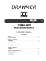
1
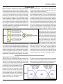
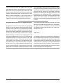
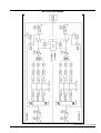
DRAWMER
THREE-SUM
Multi-Band Interface
OPERATOR’S MANUAL
CONTENTS
Warranty . . . . . . . . . . . . . . . . . . . . . . . . . . . . . . . . . . . . . . . . . . . . . . . . . . . . . . . . . . . 2
Safety Consideration . . . . . . . . . . . . . . . . . . . . . . . . . . . . . . . . . . . . . . . . . . . . . . . . 2
Chapter 1 - Introduction
Introduction . . . . . . . . . . . . . . . . . . . . . . . . . . . . . . . . . . . . . . . . . . . . . . . . . . . . . . . 3
Installation . . . . . . . . . . . . . . . . . . . . . . . . . . . . . . . . . . . . . . . . . . . . . . . . . . . . . . . . 4
Audio Connections . . . . . . . . . . . . . . . . . . . . . . . . . . . . . . . . . . . . . . . . . . . . . . . . . 4
Power Connection . . . . . . . . . . . . . . . . . . . . . . . . . . . . . . . . . . . . . . . . . . . . . . . . . 5
Chapter 2 - Control Description
Control Description . . . . . . . . . . . . . . . . . . . . . . . . . . . . . . . . . . . . . . . . . . . . . . . . . 6
Chapter 3 - Operation
Operation . . . . . . . . . . . . . . . . . . . . . . . . . . . . . . . . . . . . . . . . . . . . . . . . . . . . . . . . . 8
Chapter 4 - General Information
. . . . . . . . . . . . . . . . . . . . . . . . . . . . . . . . . . . . . . . . . . . . . . . . . . . 10
If a fault develops
Contacting Drawmer. . . . . . . . . . . . . . . . . . . . . . . . . . . . . . . . . . . . . . . . . . . . . . . 10
Specification . . . . . . . . . . . . . . . . . . . . . . . . . . . . . . . . . . . . . . . . . . . . . . . . . . . . . 10
Block Diagram . . . . . . . . . . . . . . . . . . . . . . . . . . . . . . . . . . . . . . . . . . . . . . . . . . . 11
COPYRIGHT
This manual is copyrighted © 2005 by Drawmer Electronics Ltd. With all rights reserved. Under copyright
laws, no part of this publication may be reproduced, transmitted, stored in a retrieval system or translated
into any language in any form by any means, mechanical, optical, electronic, recording, or otherwise, without the written permission of Drawmer Electronics Ltd.
ONE YEAR LIMITED WARRANTY
Drawmer Electronics Ltd., warrants the Drawmer Three-Sum
Multi-Band Interface to conform substantially to the
specifications of this manual for a period of one year from the
original date of purchase when used in accordance with the
specifications detailed in this manual. In the case of a valid
warranty claim, your sole and exclusive remedy and Drawmer’s
entire liability under any theory of liability will be to, at Drawmer’s
discretion, repair or replace the product without charge, or, if
not possible, to refund the purchase price to you. This warranty
is not transferable. It applies only to the original purchaser of
the product.
For warranty service please call your local Drawmer dealer.
Alternatively call Drawmer Electronics Ltd. at +44 (0)1709
527574. Then ship the defective product, with transportation
and insurance charges pre-paid, to Drawmer Electronics Ltd.,
Coleman Street, Parkgate, Rotherham, S62 6EL UK. Write the
RA number in large letters in a prominent position on the
shipping box. Enclose your name, address, telephone number,
copy of the original sales invoice and a detailed description of
the problem. Drawmer will not accept responsibility for loss or
damage during transit.
This warranty is void if the product has been damaged by
misuse, modification or unauthorised repair.
THIS WARRANTY IS IN LIEU OF ALL WARRANTIES,
WHETHER ORAL OR WRITTEN, EXPRESSED, IMPLIED OR
STATUTORY. DRAWMER MAKES NO OTHER WARRANTY
EITHER EXPRESS OR IMPLIED, INCLUDING, WITHOUT
LIMITATION, ANY IMPLIED WARRANTIES OF
MERCHANTABILITY, FITNESS FOR A PARTICULAR PURPOSE,
OR NON-INFRINGEMENT. PURCHASER’S SOLE AND
EXCLUSIVE REMEDY UNDER THIS WARRANTY SHALL BE
REPAIR OR REPLACEMENT AS SPECIFIED HEREIN.
IN NO EVENT WILL DRAWMER ELECTRONICS LTD. BE
LIABLE FOR ANY DIRECT, INDIRECT, SPECIAL, INCIDENTAL
OR CONSEQUENTIAL DAMAGES RESULTING FROM ANY
DEFECT IN THE PRODUCT, INCLUDING LOST PROFITS,
DAMAGE TO PROPERTY, AND, TO THE EXTENT PERMITTED
BY LAW, DAMAGE FOR PERSONAL INJURY, EVEN IF
DRAWMER HAS BEEN ADVISED OF THE POSSIBILITY OF
SUCH DAMAGES.
DRAWMER
Three-Sum
Multi-Band Interface
SAFETY CONSIDERATIONS
CAUTION - MAINS FUSE
TO REDUCE THE RISK OF FIRE
REPLACE THE MAINS FUSE ONLY WITH
A FUSE THAT CONFORMS TO IEC127-2.
250 VOLT WORKING, TIME DELAY TYPE
AND BODY SIZE OF 20mm x 5mm.
THE MAINS INPUT FUSE MUST BE
RATED AT 230V=T80mA and 115V=T160mA.
CAUTION - MAINS CABLE
DO NOT ATTEMPT TO CHANGE
OR TAMPER WITH THE
SUPPLIED MAINS CABLE.
CAUTION - SERVICING
DO NOT PERFORM ANY SERVICING.
REFER ALL SERVICING TO QUALIFIED
SERVICE PERSONNEL.
WARNING
TO REDUCE THE RISK OF FIRE OR
ELECTRIC SHOCK DO NOT EXPOSE
THIS EQUIPMENT TO RAIN OR MOISTURE.
Some states and specific countries do not allow the exclusion
of implied warranties or limitations on how long an implied
warranty may last, so the above limitations may not apply to
you. This warranty gives you specific legal rights. You may
have additional rights that vary from state to state, and country
to country.
In the interests of product development, Drawmer reserve the right to modify or
improve specifications of this product at any time, without prior notice.
2
DRAWMER THREE-SUM OPERATOR’S MANUAL
CHAPTER 1
DRAWMER
THREE-SUM
MULTI-BAND INTERFACE
INTRODUCTION
The benefits of multi-band processing, with the ability to
apply different parameters to different sections of the audio
bandwidth have been apparent to sound engineers for quite
some time.
However, ‘locking in’your audio to any one specific multiband unit can vastly reduce the creative options. The
desired combination of processing to deal with low
frequency energy, the vocal mid range and high frequency
detail and enhancement is not necessarily available from
any one manufacturer.
The new Drawmer THREE-SUM opens up a whole new
set of options allowing the engineer to split the audio into
two or three bands and apply his or her own sonic signature
to each part of the audio bandwidth.
The THREE-SUM employs a high quality signal path
culminating in a variable threshold, brick wall limiter section
with bypass facility. To ensure transparency the limiter
design is ‘two stage’, applying different processing to the
H.F. content of the material. In applications where the
dynamics of the material need to be retained to create an
open sound, the limiter is essential for catching peaks.
The THREE-SUM has been designed for use in high-end
mastering and general recording applications, alternatively,
it can transform a project studio, equipped only with ‘single
band’ processors, into a serious multi-band facility.
The Key Features are as follows:
• Continuously Variable Band Splitting
• Switchable Mute & Bypass On Each Band
• Variable Threshold, Two Stage Brick Wall Limiter Section
• Two Or Three Band Operation
• VU Metering With +10dB Re-Scale Mode For Hot Output Levels
• Variable Input & Output Levels
• Individual Band Or Multi-Band Processing
• High Quality, Minimal Signal Path With Balanced XLR Inputs/Outputs
Applications:
• Mastering • Stereo Sweetening • Bass Tracks • Drum Tracks • Voice Smoothing
• Use More Creatively - Single Band Distortion / Reverb / Delay
DRAWMER THREE-SUM OPERATOR’S MANUAL
3
INSTALLATION
The THREE-SUM is designed for standard 19" rack
mounting and occupies 1U of rack space. Avoid mounting
the unit directly above power amplifiers or power supplies
that radiate significant amounts of heat. Always connect
the mains earth to the unit. Fibre or plastic washers may
be used to prevent the front panel becoming marked by
the mounting bolts.
AUDIO CONNECTIONS
The inputs and outputs are electronically balanced on conventionally wired XLRs (pin 1 screen, pin 2 hot, pin 3 cold and
XLR shell is connected to chassis). The operating level is nominally +4dBu. Balanced use is recommended.
• Interference:
If the unit is to be used where it maybe exposed to
high levels of disturbance such as found close to a TV
or radio transmitter, we advise that the unit is operated in a balanced configuration. The screens of the
signal cables should be connected to the chassis connection on the XLR connector as opposed to connecting to pin1. The Three-Sum conforms to the EMC
standards.
• Ground Loops:
If ground loop problems are encountered, never disconnect the mains earth, but instead, try disconnecting the signal screen on one end of each of the cables
connecting the outputs of the Three-Sum to the
patchbay. If such measures are necessary, balanced
operation is recommended.
fig.1 TYPICAL THREE-SUM SETUP
4
DRAWMER THREE-SUM OPERATOR’S MANUAL
fig.2 THREE-SUM REAR CONNECTOR WIRING
POWER CONNECTION
The Three-Sum unit will be supplied with a power cable suitable for domestic power outlets in your country. For your own
safety, it is important that you use this cable to connect to the mains supply earth. The cable must not be tampered with
or modified.
The power supply socket has an integral fuse drawer containing the power fuse of the same value, to suit the mains
voltage for which the unit has been supplied. Removal of
the drawer is only possible with the power cord removed.
The fuse should never blow under normal operation. If the
fuse is suspected of having blown, then a fault will have
occurred and this fault condition should be inspected by a
qualified service engineer. When replacing the fuse, always
comply with the Safety Instructions.
If the unit is to be used with a mains input operating voltage
different to that for which the unit is supplied, the following
procedure must be carried out by a technically competent
person, (see following diagrams)
Fuse
fig.3 The Location of the Fuse
1: Disconnect the unit from the mains.
2: Using a number 1 size pozidrive screwdriver,
remove the eleven self -tapping screws that retain
the top cover. One screw is located in the top centre
of the front panel (next to the “PEAK LEVEL” text);
six screws are located on the top cover; and two
screws on either side.
Voltage
Selector
Switch
3: Inside the unit slide the voltage change-over switch
(SW8) until the correct (or nearest) mains input
voltage is visible on the switch actuator.
(see fig.4)
4: In the fuse draw change the fuse to suit the following
values:
For 230 Volt operation alter the fuse to a similar type
rated at T80mA.
For 115 Volt operation alter the fuse to a similar type
rated at T160mA.
fig.4 The Voltage Selector Switch
DRAWMER THREE-SUM OPERATOR’S MANUAL
5
CHAPTER 2
CONTROL DESCRIPTION
Input Level Trim:
-10dB - +10dB
Typically, the Input Trim level control is used to match the output of the preceding
device to the input needs of the three compressors that the signal will pass
through. Alter the “Meter Input/Output Switch” to "input" to see the effect of the
input trim on the signal level to the three compressors.
On an optimal signal the 0dB provides optimum headroom and signal-to-noise
ratio. If the input trim is set too low little compression will occur (and, raising the
overall output level of the signal will amplify the noise floor). Alternatively, increasing
the input trim control pushes more level into the compressors and therefore more
compression occurs.
Low Split Frequency: 18Hz - 1.6kHz
Sets the frequency point at which the split between low and mid bands occurs.
High Split Frequency: 530Hz - 42kHz
Sets the frequency point at which the split between mid and high bands occurs.
THREE BAND
Switches:
Low: is the signal below that set by the Low Split Frequency;
Mid: is the signal between that set by the two Split Frequency controls;
High: is the signal above that set by the High Split Frequency control.
Across all three bands
Mute:
In the “MUTE” position the signal for that particular band is effectively turned off.
Any combination of mute is available - to hear only the signal of the low band
mute the mid and high bands etc.
Bypass:
In the “BYPASS” position the signal for the low, mid, or high band is allowed to
pass through to the summing stage without being output to a compressor.
Using a combination of mute and bypass switches for the various bands allows
the operator to hear and monitor only the frequencies that are required and so
tune the low and high frequency settings.
Output Gain:
-10dB - +10dB
After the three bands have returned to the Three-Sum the signal is summed back
to a single stereo band. If at this point the signal is too low or so high that
eccessive limiting occurs then it would be difficult to adjusts all three gain controls
of each compressor whilst maintaining the low/mid/high balance, for this reason
a single OUTPUT GAIN control has been incorporated.
Adjust so that the limiter works only on signal peaks.
6
DRAWMER THREE-SUM OPERATOR’S MANUAL
Limiter
The signal culminates in a variable threshold, brick wall limiter. The limiter can
be bypassed completely using this switch in the OUT position. When in bypass
the unit will sum the three bands back to a full band stereo signal but then no
further processing is applied (the VCA is also bypassed). This is ideal for the
purists who would prefer to keep the signal path as simple as possible, but it
does mean the signal level will have to managed by themselves elsewhere.
Peak Level
0dB - +16dB
Sets an absolute limit to the level that the output signal will not be permitted to
exceed. This limiter is very fast acting enabling it to control any peaks without
audible distortion.The Output Gain control should be used to ensure that the
peak limiter operates only rarely if at all, if it is to be used purely for peak protection.
Alternatively, it may be deliberately driven into limiting to produce creative effects.
G.R. Meter
-1, -3, -6, -10dB
VU Meter
A moving coil VU meter monitors either the level of the output or input signal.
Because the meter has VU characteristics, it closely reflects what is actually
being heard, though will not respond quickly enough to register short signal
peaks.
Meter Options:
VU+10dB / VU
A two-position switch adjusts the meters to show either normal output level or
VU +10dB mode, which re-scales the meter for users working at ‘hot’ output
levels. In other words, with the switch at VU +10dB the VU meter reads 0dB but
the actual level is +10dB.
Input / Output
A two-position switch adjusts the meters to show either input or output level.
In the input position the signal level is derived after the input gain, but preceeding
the split into its three bands. This always monitors the full band of the audio
signal;
In the output positon the signal level comes after the three band signal has been
summed and passed through the output gain and limiter. If any of the bands have
been muted or bypassed this is also reflected in the meter.
DRAWMER THREE-SUM OPERATOR’S MANUAL
7
CHAPTER 3
OPERATION
Most conventional compressors work by processing the
full-band of the music, where the whole of the signal is
compressed using the same controls, however, this is by
no means perfect. A problem occurs whereby when a peak
occurs, such as the beat of a kick drum, all of the signal
is effectively "turned down" by the compressor, including
the vocals, guitar, hi-hats etc. even though these may not
need compressing. In addition, when processing complex
mixes using a conventional compressor, you can easily
reach the point where gain pumping becomes audible, with
high-energy, low-frequency sounds affecting the gain of
the whole mix. Multi-band compressors were designed to
avoid these problems, by treating different sections of the
frequency spectrum independently.
The Drawmer Three-Sum has been designed to allow the
audio to split into three separate frequency bands by means
of a crossover circuit, each band then being treated with a
separate compressor and, at the output, the various bands
are again combined to provide a full-range signal. In addition,
unlike conventional three band compressors, the Drawmer
Three-Sum allows the three signals to be sent to three
independent compressors, each giving their own unique
Setting up the Cross-Over Points.
Which cross-over frequencies should be used? This
invariably depends on the material being processed, the
settings of a mix will be very different from that of a full
drum kit, however the general rule of thumb is that in most
circumstances the cross-over points need to
be set in such a way as to separate the main
bass and treble sounds from the mid-range.
Keeping in mind that instruments have
harmonics that can extend over several
octaves, the goal is to try to partition your
mix into bands. Play your mix, and mute the
bands not required. Now you can hear exactly
which frequencies are contained in each
band, and can tune in to the signal.
8
flavour to the music - some warmer at bottom end
compression, others providing an enhanced top end. The
control is entirely with the operator.
The Drawmer Three-Sum, where each band's compressor
can be adjusted separately, is a very versatile and powerful
tool. For instance, the perceived amount of bass can be
increased by setting a higher ratio or lower threshold for
the bass band than in the mid and high bands. Similarly,
if you feel the mid frequencies of the mix are lacking, simply
turn up the output level of the mid-band compressor - using
more compression in the mid-band can often help lift out
the vocals. Likewise, compress the top end a little harder
to give it more brightness or enhancement. If the gain
reduction of each band is controlled by adjusting the makeup gain knobs on each of the three
compressors then the overall levels of
signal peaks will not increase but the
sound will be much more impressive.
However, no matter how much care is
taken, it is quite possible to fully control
the signal in each band but still end up
with a signal that is too high in level
when the bands are combined.
Therefore an output gain control has
been provided on the Three-Sum to trim
the whole stereo signal, followed by a fast acting limiter
that will catch any overshoots. To ensure transparency
the limiter design is ‘two stage’, applying different
processing to the H.F. content of the material. In
applications where the dynamics of the material need to
be retained to create an open sound, set the output gain
so that the limiter only activates on fast signal peaks.
On a full mix the kick drums and bass instruments will be
mainly in the low band while the mid band should be set
wide enough to accommodate the full vocal range, except
for perhaps the highest harmonics and breath noises -
DRAWMER THREE-SUM OPERATOR’S MANUAL
setting a crossover point in the middle of the vocal range
can completely mess up the vocal sound. In general it's
best to set the low crossover point below the vocal
frequency range (about 150Hz to 250Hz) and set the high
crossover point between 5kHz and 8kHz (but no lower
3kHz) to catch the brightness of an acoustic guitar or
cymbals etc, and embellish the feeling of detail and air,
creating an effect similar to that of using an enhancer.
Using Multi-Band Compression on Single Instruments.
The Drawmer Three-Sum can be used to very good effect
during the recording stages. Because the signal is split
into three each band can be compressed and modified
much more precisely to add bass, or enhanced top end
brightness of a single instrument, such as a piano or drum
kit. Obviously, all instruments are different and require
different settings. As before a good starting point is to
mute the unwanted bands and to tune into the required
frequencies using the "Low Split Frequency" and "High
Split Frequency" controls. This ensures that the overall
sonal quality of the instrument is compressed, but the
unwanted noises, such as rumble from traffic, or amplifier
hiss etc. are not. On vocals multi-band compressors can
be used to alter the timbre. Compressing the lower band
will provide a much thicker voice giving it presence, whilst
In all cases listen to the audio and try to determine where
the signal is lacking, the different ranges covered by the
various instruments and sounds and adjust the crossover
points accordingly. However, try to be subtle, remember
that the more make-up gain you apply, the more you will
be bringing up the background noise — tape hiss etc.
Careful selection of crossover points and ratio/threshold
settings can help to subdue any adverse effects, but
remember, over processing is always damaging to a piece
of music.
compressing the top band will improve air and give a more
sweet sound to what was a quite dull voice. Remember,
any gain should be controlled by the three individual
compresses before being summed by the Three-Sum.
Subtlety is the key.
Other Uses.
The Drawmer Three-Sum has primarily been designed for
use as a three band compressor, however, the fact that it
uses external compressors after splitting the signal into
its three bands opens up endless other uses. The signal
need not pass to a compressor, try using it to add distortion
or reverb to only the bass of a guitar or other instrument.
Imagine having a lead guitar with over driven bottom strings,
but a clear crisp tone to the top strings.
DRAWMER THREE-SUM OPERATOR’S MANUAL
9
CHAPTER 4
GENERAL INFORMATION
It is the responsibility of the installer to ensure that the continuous power rating of the speakers is not exceeded, as Drawmer
Electronics Ltd will not accept any responsibitlity for speaker damage caused by incorrect settings.
IF A FAULT DEVELOPS
CONTACTING DRAWMER
For warranty service please call Drawmer Electronics Ltd. or
their nearest authorised service facility, giving full details of
the difficulty.
Drawmer Electronics Ltd., will be pleased to answer all
application questions to enhance your usage of this
equipment. Please address correspondence to:
A list of all main dealers can be found on the Drawmer
webpages.
On receipt of this information, service or shipping instructions
will be forwarded to you.
No equipment should be returned under the warranty without
prior consent from Drawmer or their authorised representative.
For service claims under the warranty agreement a service
Returns Authorisation (RA) number will be issued.
Write this RA number in large letters in a prominent position
on the shipping box. Enclose your name, address, telephone
number, copy of the original sales invoice and a detailed
description of the problem.
Authorised returns should be prepaid and must be insured.
Drawmer (Technical Help line)
Coleman Street
Parkgate
Rotherham
S62 6EL
UK
Alternatively contact us by E-mail on :
[email protected]
Further information on all Drawmer dealers, Authorised service
departments and other contact information can be obtained
from our web pages on:
http://www.drawmer.com
All Drawmer products are packaged in specially designed
containers for protection. If the unit is to be returned, the original
container must be used. If this container is not available, then
the equipment should be packaged in substantial shock-proof
material, capable of withstanding the handling for the transit.
THREE-SUM MULTI-BAND INTERFACE
DATA SPECIFICATION
INPUT IMPEDANCE
Input Impedance
Maximum Input Level
THD & Noise
20k Ohms
+20dBu
-85dB
POWER REQUIREMENTS
230Volt or 115V at 50-60hZ, 13VA
OUTPUT
Output Impedance
Maximum Output Level
50 Ohms
+21dBu
FUSE RATING
<20Hz to 20kHz +/- <.5dB
<17Hz to 28kHz -1dB
<10Hz to 47kHz -3dB
FUSE TYPE
T80mA for 230Volt, T160mA for 115Volt
Conforming to IEC 127-2
BANDWIDTH
20mm x 5mm, Class 3 Slo-Blo, 250Volt working
CASE SIZE
CROSSTALK
482mm (W) x 44mm (H) x 200mm (D)
better than 63dB @ 10kHz
WEIGHT
10
DRAWMER THREE-SUM OPERATOR’S MANUAL
4Kgs
BLOCK DIAGRAM
Three-Sum ver 01 B 15/06/06
DRAWMER THREE-SUM OPERATOR’S MANUAL
11