1
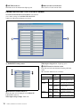
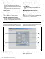
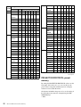
2-190-733-11 (1)
SRP-X500P Manager
User’s Guide
Software Version 1.0
Before using the software, please read this User’s Guide and the Operating Instructions of the
SRP-X500P Digital Powered Mixer thoroughly and retain them for future reference.
SRP-X500P
© 2004 Sony Corporation
Table of Contents
Overview.................................................................................3
Features ...................................................................................... 3
Using the supplied CD-ROM..................................................... 3
Operating conditions .................................................................. 3
Preparation.............................................................................4
Installing the SRP-X500P Manager........................................... 4
Uninstalling................................................................................ 4
Names and Functions of Controls on Screen.....................5
Common operation section ........................................................ 5
BLOCK screen........................................................................... 6
PANEL VIEW screen ................................................................ 9
OVER VIEW screen ................................................................ 10
REMOTE FADER screen ........................................................ 15
PARALLEL/PROJECTOR CONTROL screen....................... 16
SCENE MEMORY screen....................................................... 18
About the Mixer’s Internal Preset Memory........................ 19
SYSTEM TYPE preset memory .............................................. 19
PROJECTOR PROTOCOL preset memory ............................ 20
To Control the Projector Whose Protocol Is Not Preset to
the Mixer ........................................................................ 21
Appendix .............................................................................. 25
Factory settings (SYSTEM TYPE 0)....................................... 25
2
Overview
Operating conditions
The recommended operating environment for using the
SRP-X500P Manager is as follows.
Features
OS
Microsoft Windows Millennium Edition
Microsoft Windows 2000 Professional
The SRP-X500P Manager is a program which allows you
to make parameter settings for the SRP-X500P Digital
Powered Mixer.
Microsoft Windows XP Professional
Microsoft Windows XP Home Edition
CPU
Celeron 400 MHz or higher
Various effector settings
RAM
128 MB of RAM or greater
Detailed settings on equalizer, automatic gain control,
compressor, etc. can be performed. The SRP-X500P
Manager is provided with visual aids including graphs to
allow easy operation.
Available hard
20 MB of available hard-disk space
Remote settings
Settings for the REMOTE PARALLEL connector on the
rear of the SRP-X500P Digital Powered Mixer and settings
for projector control can be performed.
disk space
Notes on use
• The PC must be preinstalled with one of the OS listed
above. Operation of this software when the OS has been
upgraded is not guaranteed.
• Operation this software is not guaranteed in every PC,
even if the recommended environment is satisfied.
Scene memory
You can store the settings as scene files to the internal
memory of the SRP-X500P Digital Powered Mixer. You
can change the settings at a time by recalling the scene.
Using the supplied CD-ROM
The CD-ROM contains the following files.
SRP-X500P Manager
This is a program for setting the SRP-X500P parameters
from a PC.
SRP-X500P Manager User’s Guide
This is a PDF file containing information on the functions
and operations of the SRP-X500P Manager. Can be
viewed on a PC.
SRP-X500P Operating Instructions
This is a PDF file containing information on the functions
and operations of the SRP-X500P Digital Powered Mixer.
Can be viewed on a PC.
To open these PDF files, Adobe Acrobat or Adobe Reader
must be installed on your PC.
To get Adobe Reader, go to the website of Adobe Systems
Incorporated (http://www.adobe.com/).
Overview
3
Preparation
Installing the SRP-X500P Manager
1
Insert the supplied CD-ROM into the CD-ROM drive
of the personal computer.
2
Open the SRP-X500P Manager\English folder
double-click the Setup icon.
“Welcome to the SRP-X500P Manager setup
wizard.” screen appears.
Uninstalling
1
Click the Start menu and select “Settings (S)”. Then
click “Control Panel” to open it.
2
Double-click the “Add/Remove Programs” icon and
select “SRP-X500P Manager” from the list of the
“Install/Uninstall” tab.
3
Click “Add/Remove (R)...”.
This completes the uninstallation.
Note
3
Click “Next”.
“Select Installation Folder.” screen appears.
Note
The SRP-X500P Manager folder is created in
C:\Program Files. To change the installation
destination, click “Browse...”.
4
After specifying the installation destination, click
“Next”.
“Confirm Installation.” screen appears.
5
Click “Next”.
Installation stars.
6
After “Installation Complete.” screen appears, click
“Close”.
“Confirm Installation.” screen appears.
Installation of the SRP-X500P Manager is now complete.
4
Preparation
When using Microsoft Windows 2000 Professional,
Microsoft Windows XP Professional or Microsoft
Windows XP Home Edition, be sure to log on as the user
having administrator authority, then perform the
installation or uninstallation.
Names and Functions of Controls on Screen
Common operation section
The controls shown below appear on all the screens.
A Menu bar
The titles of the menus are displayed.
You can perform operations that are common to the basic
settings and each setup screen.
a File menu
This software allows you to save the parameters of up to 8
scenes and the information in a single setup file (*.x5p).
New: Creates a new setup file. Cannot be selected when
communication between the SRP-X500P Manager
and the SRP-X500P Digital Powered Mixer (referred
to as “mixer” hereafter) is active.
Open: Opens an existing setup file. When “Open” is
selected while the communication between the SRPX500P Manager and the mixer is active, all parameters
within the current setup file is transmitted to the mixer.
Open scene: Opens the specified scene number from the
8 scenes in the existing setup file.
A Select a setup file.
B The information contained in the selected setup file is
displayed.
C Select the scene number.
Names and Functions of Controls on Screen
5
D The index of the selected scene number is displayed.
E Click the Open button.
Save: Saves the new data by overwriting the existing data.
Save as: Saves the data under a different name.
Exit: Exits the SRP-X500P Manager.
b Communication menu
Activates/deactivates the communication between the
SRP-X500P Manager and the mixer. Also specifies the
port number for RS-232C communication.
Connect: Activates communication. Cannot be selected
when the communication between the SRP-X500P
Manager and the mixer is already activated.
Disconnect: Deactivates communication. Cannot be
selected when the communication between the SRPX500P Manager and the mixer is already deactivated.
Port select: Specifies the port number for RS-232C
communication to be used for SRP-X500P Manager
operation.
A Enter a password.
B For confirmation, enter the same password again.
C Click “OK”.
Note
c Options menu
Factory preset: Resets all parameters to the default
settings.
Password setting: You can set a password.
If you enter the wrong password, you cannot start the SRPX500P Manager. Be sure to take a note of the password.
If you forget the password, uninstall the software and then
reinstall it from the supplied CD-ROM.
d Help menu
About: The version of the software appears.
B Screen selection tabs
Click to select the setup screen for each parameter.
C CONNECTION indicator
Lights up green when the communication between the
SRP-X500P Manager and the mixer is activated.
BLOCK screen
The BLOCK screen shows the internal block diagram of
the mixer. You can click the button to turn each function
on or off while monitoring overall settings on this screen.
6
Names and Functions of Controls on Screen
A MIC INPUT setting section
+48V: Lights up red when the +48 V ON/OFF switch on
the mixer is set to ON.
b Index name input box
You can enter an index name for each input channel. Up to
eight alphanumeric characters can be entered.
c TRIM indication
Displays the reference level of the input channel specified
by the TRIM control on the mixer within the range of –60
dBu to –30 dBu.
d Level meter
Displays the signal level of the input channel.
a Indicators
These are the indicators of microphone input.
RF: Lights up green when the RF signal is input to the
wireless tuner unit which is installed in the mixer.
AF: Lights up yellow when the audio signal is input to the
wireless tuner unit which is installed in the mixer.
WL: Lights up green when the signal is input to the mixer
from the wireless tuner unit installed to the mixer. As
long as this indicator is lit, the mixer selects the signal
input from the wireless tuner unit.
e LCF, FR/EQ, and AGC buttons
Click to turn each function on or off. The button lights up
green when it is set to on.
f MUTING button
Left-click to turn muting function on or off. The button
lights up red when it is set to on.
g Fader level indication
Displays the fader level of the input signal. The displayed
value is the summation of the level of the INPUT fader and
remote fader specified by the software and the input level
control setting on the mixer.
Names and Functions of Controls on Screen
7
B LINE, AV/RGB INPUT setting section
a TRIM indication
Displays reference level specified by the TRIM control on
the mixer.
b Level meter
Displays the signal level of each input channel.
c AV/RGB SELECTOR buttons
Click to select one of the AV/RGB channels (A to E). The
button for the selected channel lights up green.
D OUTPUT setting section
d SIGNAL DEFINE indication
Displays the signal format specified in the PROJECTOR
CONTROL setting section of the REMOTE PARALLEL/
PROJECTOR CONTROL screen.
e PROJECTOR PROTOCOL indication
Displays the projector protocol setting specified by the
PROJECTOR PROTOCOL selector on the mixer and
model name of the projector.
For details on the MUTING button, fader level indication,
entering the index name for the input signal, see “A MIC
INPUT setting section” of the BLOCK screen (page 7).
C ROUTING setting section
With this section, you can select an output path for each
input signal by assigning each input channel to an output
channel.
Left-click a channel button to turn the corresponding
channel on or off. Right-click the button to specify the
sending level of the input signal to the output channel.
When the channel button is set to on and the sending level
is set to 0 dB, it lights up green. The button lights up blue
when it is set to on and the sending level is set to –3 dB to
–20 dB.
a DELAY button
Click to turn the delay on or off. The button lights up green
when the delay is set to on.
8
Names and Functions of Controls on Screen
Note
The total amount of delay time to be set for the total output
channel must not exceed 160 ms (54.7 m or 181.9 feet).
For details, see “DELAY amount setup box” (page 13).
b PROTECTION indicator
Lights up red when the PROTECTION indicator on the
mixer lights up red.
c ATT indication
Shows the attenuation level specified by the SPEAKER
OUT controls on the mixer.
d CLIP indicator
Lights up red when the CLIP indicator on the mixer lights
up red.
e LINK check box
Check the muting, compressor, delay, and output fader
settings for the SPEAKER 1 and 2, SPEAKER 3 and 4,
LINE 1 and 2, or LINE 3 and 4 to link with each other.
f 70V LINE check box
Check to set the SPEAKER 3 and 4 channels to 70V LINE.
PANEL VIEW screen
The PANEL VIEW screen shows the settings performed
through the front panel of the mixer and the system type
setting,
A FRONT PANEL VIEW display section
Shows the settings performed through the front panel of
the mixer.
If you save the current status of this section to the setup
file, position of the controls and switches of the mixer can
be recalled later. Then, by setting the controls and switches
so that the markers representing them on the screen light
up green, the front panel status can be easily reproduced.
B SYSTEM TYPE display section
Shows the image of the system type specified by the
SYSTEM TYPE selector on the front panel of the mixer.
C PROJECTOR PROTOCOL display section
Displays the projector number specified by the
PROJECTOR PROTOCOL selector on the front panel of
the mixer and index name of the projector.
D INFORMATION input section
Up to 128 alphanumeric characters can be entered.
Names and Functions of Controls on Screen
9
OVER VIEW screen
The detailed settings on equalizer, automatic gain control,
etc., for each channel can be performed.
A MIC INPUT setting section
b Level meter
Displays the signal level of the input channel.
c Indicators
These are the indicators of microphone input.
RF: Lights up green when the RF signal is input to the
wireless tuner unit which is installed in the mixer.
AF: Lights up yellow when the audio signal is input to the
wireless tuner unit which is installed in the mixer.
WL: Lights up green when the signal is input to the mixer
from the wireless tuner unit installed to the mixer. As
long as this indicator is lit, the mixer selects the signal
input from the wireless tuner unit.
+48V: Lights up red when the +48 V ON/OFF switch on
the mixer is set to ON.
d Index name indication
Shows the index name of the input channel entered in
index name column of the BLOCK screen.
a TRIM indication
Displays the reference level of the input channel specified
by the TRIM control on the mixer within the range of –60
dBu to –30 dBu.
10
Names and Functions of Controls on Screen
e AGC (Automatic Gain Control) button
Left-click to display the AUTO GAIN CONTROL setting
screen.
K GAIN CONTROL indication
Shows the amount of gain control obtained by the
AGC function.
L CLOSE button
Click to close the AUTO GAIN CONTROL setting
screen.
f FR/EQ (Feedback Reducer/Equalizer) button
Left-click to display the MIC INPUT EQUALIZER
setting screen.
A Characteristics graph
Displays the characteristics of the automatic gain
control. By dragging the marker with the mouse,
threshold level and ratio of the compressor and
threshold level of the gate can be changed.
B ON button
Click to turn the automatic gain control on or off.
When set to on, this button lights up green.
C COMPRESSOR THRESHOLD setup box
Specifies the threshold level of the compressor. The
level can be set within the range of –60 dB to +20 dB,
in 1-dB steps.
D RATIO setup box
Specifies the ratio of the compressor. The value can be
set within the range of 1 : 1 to ∞ : 1, in 14 steps.
E MAKE GAIN setup box
Specifies the make up gain value. The value can be set
within the range of 0 dB to +10 dB, in 1-dB steps.
F GATE THRESHOLD setup box
Specifies the threshold level of the gate. The value can
be set within the range of –60 dB to 0 dB, in 1-dB
steps.
G RANGE setup box
Specifies the range of the gate. The value can be set
within the range of –60 dB to 0 dB, in 1-dB steps.
H ATTACK setup box
Specifies the attack time. The value can be set within
the range of 0.1 ms to 33000 ms, in 32 steps.
I HOLD TIME setup box
Specifies the hold time. The value can be set within the
range of 0.1 ms to 33000 ms, in 32 steps.
J RELEASE setup box
Specifies the release time. The value can be set within
the range of 0.1 ms to 33000 ms, in 32 steps.
A Channel selection button
Selects the input channel that you want to set. The
selected button lights up yellow. To select the other
channel, left-click the corresponding button.
B Equalizer pattern graph
Appears when “EQ” is selected on the FR/EQ
selection radio button.
The markers with the same color as the corresponding
band in the EQ parameter appear on the graph. You
can change the gain and frequency for each band by
dragging the corresponding marker with the mouse.
Right-clicking the marker returns the gain to 0 dB.
You can also change the Q value by rolling the center
wheel of the mouse up or down.
C LCF (low-cut filter) button
Each click on this button toggles the low-cut filter
between on and off. This button lights up green when
set to on. The low-cut filter reduces low-frequency
components such as blowing noise and makes the
sound clearer.
D FR/EQ button
Each click on this button toggles the feedback reducer
or equalizer between on and off. This button lights up
green when set to on.
E FR/EQ selection radio buttons
Names and Functions of Controls on Screen
11
Click “FR” or “EQ” to select the function of equalizer
as the feedback reducer or the parametric equalizer.
FR: The feedback reducer setting screen appears.
When “FR” is selected, the EQ parameter 1 to 5
columns become inactive and FR SETUP button
becomes active.
EQ: The 5-band parametric equalizer setting screen
appears. When “EQ” is selected, the EQ parameter
1 to 5 columns become active and FR SETUP
button becomes inactive.
Note
Changing the parametric equalizer setting will cancel
the howling suppression. When you use the equalizer
as the parametric equalizer, make the setting carefully
not to affect the howling suppression.
F FR SETUP button
Left-click to display the channel selection dialog box.
With the dialog box, select the channel and click OK
button to carry out the automatic setting of the
feedback reducer (function to suppress the positive
acoustic feedback by detecting the frequency that
causes howling in advance and by reducing the gain of
the frequency).
Note
The FR SETUP button becomes operative only when
the communication between the SRP-X500P Manager
and the mixer is active and “FR” is selected on the FR/
EQ selection radio buttons.
G EQ parameter setup boxes
Set the frequency, Q-value, and gain for each equalizer
band. Values can be set by clicking on the S/s
buttons or by entering numerical value directly.
H CLOSE button
Click to close the MIC INPUT EQUALIZER setting
screen.
b Level meters
Displays the signal level of each input channel.
c TRIM indication
Displays the reference level of the input channel specified
by the TRIM control on the mixer. For the signal input
from the AV/RGB INPUT connectors, the reference level
is displayed along with the SELECT buttons indication
(e.g., A:–3 dB).
d SELECT buttons
Click to select one of the AV/RGB channels (A to E). The
button for the selected channel lights up green.
g MUTING button
Left-click to turn muting function on or off. The button
lights up red when it is set to on.
e MUTING button
Left-click to turn muting function on or off. The button
lights up red when it is set to on.
h Input fader
You can adjust the input level by dragging the input fader.
The yellow triangler marker displayed on the side of the
fader indicates the fader position which is the sum of the
input fader setting and the input level control settings on
the mixer.
f Input fader
You can adjust the input level by dragging the input fader.
The yellow triangler marker displayed on the side of the
fader indicates the fader position which is the sum of the
input fader setting and remote fader setting on the software
and the input level control settings on the mixer.
B LINE, AV/RGB INPUT setting section
12
a Index name indication
Shows the index name of the audio signal input from the
LINE IN connectors or the AV/RGB INPUT connectors
(A to E). For the signal input from the AV/RGB INPUT
connectors, the index name is displayed along with the
SELECT buttons indication (e.g., A:INDEX).
Names and Functions of Controls on Screen
C DELAY indication section
a DELAY REMAIN indication
The total amount of delay time to be set for the total output
channels must not exceed 160 ms (54.7 m, or 181.9 feet).
After the DELAY REMAIN indication shows 0%, the
amount of delay time cannot be increased.
b UNIT setup box
Allows you to select the unit of the delay from the
following: ms, meter, feet.
D Routing setting section
With this section, you can select an output path for each
input signal by assigning each input channel to an output
channel.
The buttons on the first row are for the MIC INPUT
channels. The buttons on the middle row are for the LINE
INPUT L/R channels, and the buttons located on the last
row are for the AV/RGB INPUT L/R channels.
Left-click a channel button to turn the corresponding
channel on or off. Right-click the button to specify the
sending level of the input signal to the output channel.
When the channel button is set to on and the sending level
is set to 0 dB, it lights up green. The button lights up blue
when it is set to on and the sending level is set to –3 dB to
–20 dB.
E Output channels setting section
With this section, settings related to output channels can be
performed.
a DELAY button
Turns the delay time function on or off. The button lights
up green when the delay is turned to on.
b DELAY amount setup box
Allows you to select the amount of delay. The value can be
set by clicking on the S/s buttons or by entering
numerical value directly. The amount of delay is shown in
units specified in the UNIT setup box on the DELAY
indication section.
Note
The total amount of delay time to be set for the total output
channels must not exceed 160 ms (54.7 m, or 181.9 feet).
Determine the amount of delay time by watching the
DELAY REMAIN indication on the DELAY indication
section.
c Speaker output indicators
PROTECTION: Lights up red when the PROTECTION
indicator on the mixer lights up red.
CLIP: Lights up red when the CLIP indicator on the
mixer lights up red.
d ATT indication
Shows the attenuation level specified by the SPEAKER
OUT controls on the mixer.
e 70V LINE check box
Check to set the SPEAKER 3 and 4 channels to 70V LINE.
f LINK check box
Check the parameter settings for the SPEAKER 1 and 2,
SPEAKER 3 and 4, LINE 1 and 2, or LINE 3 and 4 to link
with each other.
Names and Functions of Controls on Screen
13
Notes
• Even when the LINK check box is checked, equalizer
settings are not linked between the 2 channels.
• When the sum of delay amount or compressor amount
exceeds the limit due to linkage of the 2 channels, a
warning message appears. If this occurs, reduce the
amount.
g COMP button
Left-click to display the COMPRESSOR setting screen.
H ATTACK setup box
Specifies the attack time.
I RELEASE setup box
Specifies the release time.
J CLOSE button
Click to close the COMPRESSOR setting screen.
h EQ button
Left-click to display the OUTPUT EQUALIZER setting
screen.
A Channel selection buttons
The selected button lights up yellow. To select the
other channel, left-click the corresponding button.
B ON indicator
The indicator for the channel whose compressor
setting is turned on lights up green.
C Characteristics graph
Displays the characteristics of the compressor. By
dragging the markers with the mouse, threshold level
and ratio of the compressor can be changed.
D ON button
Left-click to turn the compressor on or off. When set
to on, this button lights up green.
Note
Compressor can be simultaneously applied to up to 4
output channels.
E GAIN REDUCTION indicator
Shows the amount of attenuation of the gain.
F THRESHOLD setup box
Specifies the threshold level of the compressor.
G RATIO setup box
Specifies the ratio of the compressor.
A Channel selection buttons
The selected button lights up yellow. To select the
other channel, left-click the corresponding button.
B Number of bands setup box
Use the pull-down menu to select the number of bands
to set the parameters. 0, 3, 6, 9, or 12 bands can be
selected. The parameter setup boxes corresponding to
the selected number of bands become active.
Note
The total amount of equalizer bands to be applied to
the total output channels must not exceed 24 bands.
While setting the equalizer for the output channels, be
sure that the total number of equalizer bands is 24 or
less.
C Equalizer pattern graph
The markers with the same color as the corresponding
band in the EQ parameter appear on the graph. You
can change the gain and frequency for each band by
dragging the corresponding marker with the mouse.
Right-clicking the marker returns the gain to 0 dB.
You can also change the Q value by rolling the center
wheel of the mouse up or down.
D ON button
14
Names and Functions of Controls on Screen
Left-click to turn the equalizer on or off. When set to
ON, this button lights up green.
E Equalizer parameter setup boxes
Set the frequency, Q-value, and gain for each equalizer
band. Values can be set by clicking on the S/s
buttons or by entering numerical value directly.
F CLOSE button
Click to close the OUTPUT EQUALIZER setting
screen.
i Output fader
You can adjust the output level by dragging the output
fader. The yellow triangular marker displayed on the side
of the fader indicates the fader position which is the sum of
the output fader setting, remote fader setting, and the
output level control settings on the mixer.
For details on the index name indication, level meters, and
the MUTING button, see “A MIC INPUT setting
section” of the OVER VIEW screen (page 10).
REMOTE FADER screen
By assigning input/output faders to the remote faders, you
can control the volume of asssined channels with single
fader operation.
The level of the MASTER fader can be controlled by the
MASTER volume control on the front panel of the mixer.
The level of the REMOTE 1 to 6 faders can be controlled
through the REMOTE PARALLEL connector on the rear
panel of the mixer.
a Index name input box
You can enter an index name for each remote fader. Up to
eight alphanumeric characters can be entered.
c Fader assignment buttons
Left-click the button to assign input/output faders to the
remote fader. The buttons corresponding to assigned input/
output faders light up green.
b Index name indication
Displays the index name entered in the BLOCK setting
screen.
Note
Input faders and output faders cannot be assigned to the
same remote fader.
Names and Functions of Controls on Screen
15
d MUTING indicator
The indicator for the muted fader lights up red.
e Remote fader level indication
Shows the level of the remote fader.
PARALLEL/PROJECTOR CONTROL screen
The PARALLEL/PROJECTOR CONTROL screen allows
you to make settings on the REMOTE PARALLEL
connector of the mixer and projector control.
A PARALLEL setting section
When input voltage is low: Lights up green.
b INPUT function selection section
Left-click and select the function from the pull-down
menu.
The selectable functions are as follows:
INPUT
Connectable Function
device
NONE
a PARALLEL INPUT indicators
Show the status of each input pin of the REMOTE
PARALLEL connector.
When input voltage is high: Turns off.
16
Names and Functions of Controls on Screen
-
None
AV/RGB
SELECT
OFF, A-E
Switch
(momentary
type)
When turned on, selects AV/RGB
SELECT setting (OFF or A-E).
MASTER
VOLUME
MUTING
Switch (latch
type)
When turned on, mutes the master
volume. Turn off to cancel muting.
UP
Switch
(momentary
type)
While turned on, keeps turning up
the master volume.
DOWN
Switch (latch
type)
While turned on, keeps turning
down the master volume.
MUTING
Switch (latch
type)
When turned on, mutes the
remote fader. Turn off to cancel
muting.
LEVEL
Volume
Adjusts the remote fader volume.
REMOTE
FADER 1-6
SCENE
RECALL
1-8
Switch
(momentary
type)
When turned on, recalls the scene
memory.
PROJECTER ON
POWER
Switch
(momentary
type)
When turned on, turns on the
projector power.
EMG
STANDBY Switch
(momentary
type)
When turned on, sets the projector
to standby status.
ON/
Switch (latch
STANDBY type)
When turned on, turns on the
projector power. Turn off to set the
projector to standby status.
OPEN
Emergency
broadcast
system
When the signal from the
emergency broadcast system is
OPEN, mutes all output channels.
Turn off to cancel muting.
CLOSE
Emergency
broadcast
system
When the signal from the
emergency broadcast system is
CLOSE, mutes all output
channels. Turn off to cancel
muting.
1
2
3
c Input level indication
Shows the input level setting on the mixer. This is
indicated only when a volume controller is connected to
the input pin.
d PARALLEL OUTPUT indicators
Show the status of each output pin of the REMOTE
PARALLEL connector.
When output voltage is low: Lights up green.
When output voltage is high: Turns off.
4
a PROJECTOR PROTOCOL indication
Shows the status of the PROJECTOR PROTOCOL
selector setting on the mixer and the name of the projector.
b PROTOCOL SETTING button
Left-click to display the PROTOCOL SETTING screen.
e OUTPUT function selection section
Left-click and select the function from the pull-down
menu.
The selectable functions are as follows:
OUTPUT
Function
NONE
None
AV/RGB
SELECT
OFF, A-E
Turns on (Low) when the corresponding channel is
selected.
MASTER
VOLUME
MUTING
Turns on (Low) when the master volume is fully
turned down.
MAX (UP) Turns on (Low) when the master volume is at the
maximum level.
REMOTE
FADER 1-6
SCENE
RECALL
MIN
(DOWN)
Turns on (Low) when the master volume is at the
minimum level.
MUTING
Turns on (Low) when the corresponding remote
fader is fully turned down.
MAX
Turns on (Low) when the corresponding remote
fader is at the maximum level.
MIN
Turns on (Low) when the corresponding remote
fader is at the minimum level.
1-8
Turns on (Low) when the corresponding scene
memory is recalled.
PROJECTER ON
Turns on (Low) when the projector is turned on.
POWER
STANDBY Turns on (Low) when the projector enters standby
status.
EMG
Turns on (Low) when all output channels are muted
by the EMG setting for the input pins (either OPEN
or CLOSE).
B PROJECTOR CONTROL setting section
With this section, settings related to projector control can
be performed.
A File menu
The projector protocol settings can be saved as a file
and can be recalled later.
B INDEX name input box
You can enter an index name the projector protocol
setting file. Up to 16 alphanumeric characters can be
entered.
C BITS PER SECOND setup box
Use the pull-down menu to select the baud rate for the
RS-232C port for projector control.
D PARITY setup box
Use the pull-down menu to select the parity bits.
Names and Functions of Controls on Screen
17
E Command input section
Enter the commands to be sent from the mixer to the
projector to turn it on, to set it to standby status, or to
select the input channel. Enter the command as a
hexadecimal number using numbers 0 to 9 and letters
A to F.
The maximum length of the command is 32 bytes.
I COMMAND SEQUENCE indication
Shows the sequence of commands and the wait time to
be sent for defining the input channel on the projector.
F WAIT input box
Specify the wait time until the another command is
sent after the projector has received the previously sent
command.
c PROJECTOR POWER setting section
By checking the SYNC WITH POWER ON checkbox,
you can interlock the power on/off control of the projector
with the POWER switch operation on the SRP-X500P.
G TEST button
Press to run the test on sending command.
d SIGNAL DEFINE selection radio buttons
Click to select the format of the video signal which is input
to each of the AV/RGB INPUT connectors.
J CLOSE button
Click to close the PROTOCOL SETTING setting
screen.
H PROJECTOR INPUT SELECT buttons
Press one of the buttons to select the signal format,
then enter the command defining the input channel on
the projector for the signal format.
SCENE MEMORY screen
18
You can store the settings that you usually use as a scene
file to internal memory of the mixer to recall it whenever
you use it. Or, by storing scene files in advance, you can
quickly deal with division of the room.
a SCENE MEMORY button
Left-click to select the scene file number.
The color of the button shows the status of the scene file
number.
Green: Currently selected.
Names and Functions of Controls on Screen
Gray: A scene file is stored.
Deep gray: No scene file is stored.
b INDEX indication
Shows the index name of the scene file.
c FUNCTIONS indication
The functions stored to the selected scene file light up
green.
d STORE button
Used to store the scene file. Left-click to display the setting
screen to allow entering the index name and selecting the
functions to be included in the scene file.
e RECALL button
Click to recall the scene file whose number is currently
selected by the SCENE MEMORY button. This button
does not work when you have selected a number with no
scene file is stored.
f CLEAR button
Click to clear the scene file whose number is currently
selected by the SCENE MEMORY button. This button
does not work when you have selected a number with no
scene file is stored.
g POWER ON SETTING radio buttons
Click to select the scene file status to be automatically
recalled when the mixer is turned on.
LAST MEMORY: The status when the power to the
mixer has been turned off resumes.
SCENE No.1: The scene file No.1 is recalled.
About the Mixer’s Internal
Preset Memory
SYSTEM TYPE preset memory
By setting the SYSTEM TYPE selector on the front panel
of the mixer to 1 to 9, you can choose the speaker system
type setting that corresponds with the AV system being
used.
Of the items included in the system type preset memory 1
to 9, the setting of the following items cannot be changed
using the SRP-X500P Manager.
• MIC INPUT Low Cut Filter
• MIC INPUT FR/EQ settings
• INPUT fader
• INPUT MUTING
• ROUTING
• Number of bands of the OUTPUT equalizer
• OUTPUT compressor
• OUTPUT fader
• OUTPUT MUTING
• OUTPUT LINK
• DELAY
• 70V LINE/Lo imp. setting for the SPEAKERS CH-3/4
terminals
• REMOTE FADER
• Scene memory
To change the setting of the items above, set the SYSTEM
TYPE selector on the mixer to “0”, turn off the mixer, and
then turn it on again.
For details on the settings other than the REMOTE
FADER, refer to the Operating Instructions supplied with
the mixer.
The preset patterns for the REMOTE FADER are shown in
the following table:
About the Mixer’s Internal Preset Memory
19
SYSTE Setting
M TYPE
4
MASTER REMOTE
1
1
2
MIC 1-4
-
a
LINE,
-
a
SP OUT 1
a
SP OUT 2
a
3
a
4
5
-
-
-
-
-
a
-
-
-
-
-
-
a
-
-
-
-
-
a
-
-
SP OUT 3
a
-
-
-
a
-
-
SP OUT 4
-
-
-
-
-
-
-
LINE OUT 1
a
-
-
-
-
a
a
LINE OUT 2
a
-
-
-
-
a
a
LINE OUT 3
-
-
-
-
-
a
-
LINE OUT 4
-
-
-
-
-
a
-
MIC 1-4
-
a
a
-
-
-
-
LINE,
-
a
-
a
-
-
-
SP OUT 1
a
-
-
-
a
-
-
SP OUT 2
a
-
-
-
a
-
-
5
a
a
-
-
-
-
-
a
-
a
-
-
-
SP OUT 1
-
-
-
-
-
-
-
SP OUT 2
-
-
-
-
-
-
-
SP OUT 3
a
-
-
-
a
-
-
SP OUT 4
-
-
-
-
-
-
-
SP OUT 3
a
-
-
-
a
-
-
SP OUT 4
a
-
-
-
a
-
-
LINE OUT 1
a
-
-
-
-
a
a
LINE OUT 2
a
-
-
-
-
a
a
LINE OUT 3
-
-
-
-
-
a
-
LINE OUT 4
-
-
-
-
-
a
-
MIC 1-4
-
a
a
-
-
-
-
LINE,
-
a
-
a
-
-
-
SP OUT 1
a
-
-
-
a
-
-
SP OUT 2
a
-
-
-
a
-
-
AV/RGB
SP OUT 3
-
-
-
-
-
-
-
SP OUT 4
-
-
-
-
-
-
-
LINE OUT 1
a
-
-
-
-
a
a
LINE OUT 2
a
-
-
-
-
a
a
LINE OUT 3
-
-
-
-
-
a
-
LINE OUT 4
-
-
-
-
-
a
-
LINE OUT 1
a
-
-
-
-
a
a
LINE OUT 2
a
-
-
-
-
a
a
LINE OUT 3
-
-
-
-
-
a
-
LINE OUT 4
-
-
-
-
-
a
-
MIC 1-4
-
a
a
-
-
-
-
LINE,
-
a
-
a
-
-
-
AV/RGB
AV/RGB
3
-
LINE,
AV/RGB
6
AV/RGB
2
MIC 1-4
6-9
SP OUT 1
a
-
-
-
a
-
-
SP OUT 2
a
-
-
-
a
-
-
SP OUT 3
a
-
-
-
a
-
-
SP OUT 4
a
-
-
-
a
-
-
LINE OUT 1
a
-
-
-
-
a
a
LINE OUT 2
a
-
-
-
-
a
a
LINE OUT 3
-
-
-
-
-
a
-
LINE OUT 4
-
-
-
-
-
a
-
MIC 1-4
-
a
a
-
-
-
-
LINE,
-
a
-
a
-
-
-
AV/RGB
SP OUT 1
a
-
-
-
a
-
-
SP OUT 2
a
-
-
-
a
-
-
SP OUT 3
a
-
-
-
a
-
-
SP OUT 4
a
-
-
-
a
-
-
LINE OUT 1
a
-
-
-
-
a
a
LINE OUT 2
a
-
-
-
-
a
a
LINE OUT 3
-
-
-
-
-
a
-
LINE OUT 4
-
-
-
-
-
a
-
a : Assigned.
- : Not assigned.
PROJECTOR PROTOCOL preset
memory
By setting the PROJECTOR PROTOCOL selector on the
front panel of the mixer to 1 to A, you can choose the
protocol that corresponds with the projector or display
monitor to be used with the mixer.
Of the items included in the protocol 1 to A, the setting of
the following items cannot be changed using the SRPX500P Manager.
• Index
20
About the Mixer’s Internal Preset Memory
• Baud rate
• Parity bit
• POWER ON and STANDBY commands and the wait
time
• VIDEO, RGB, and COMPONENT input selection
command and the wait time
To Control the Projector
Whose Protocol Is Not
Preset to the Mixer
The input selection command for OTHER TERMINAL is
not preset to the mixer.
When you input S-video signal or etc. from the video
source device directly to the projector or display monitor,
specify the input command.
Set the PROJECTOR PROTOCOL selector on the mixer
to “0”, turn off the mixer, then turn it on again.
And then, make the necessary settings in the PROTOCOL
SETTING screen.
For details on the projector or display monitor whose
protocol is preset to the mixer, refer to the Operating
Instructions supplied with the mixer.
Connectable projectors
Projectors which satisfy the following specifications can
be connected to the mixer.
• Equipped with RS-232C remote terminal
• Equipped with the RS-232C remote terminal supporting
the following specifications:
− Electrical characteristics : Conforming to RS-232C
− Baud rate : 9600, 19200 or 38400 bps
− Parity bit : None, odd or even
− Data length : 8 bits
− Stop bit : 1 bit
− Flow control : None
The RS-232C remote terminal can be used to turn on the
power, turn off the power, and select the input terminal.
Video signal systems and limitations
This system has the following limitations depending on the
video signal system used and on the operation method.
The limitations are shown below.
• When component signal is used
To Control the Projector Whose Protocol Is Not Preset to the Mixer
21
The projector is equipped with the
component signal input terminals.
No
,
The component
signal cannot be
used.
No
,
There is no
limitation.
Yes
k
There is no
limitation.
a Enter the command to turn on the projector
connected to the mixer in the command input
section of the PROTOCOL SETTING screen.
b Enter 60 seconds in the WAIT input box, then
adjust the wait time during later operation check.
Yes
j
The component signal and the
RGB signal are used together.
Note
If the commands that can be received by the projector
are specified as ASCII code, convert the ASCII code
to a hexadecimal number and enter it in the command
input section.
Yes
j
The projector has a single input
terminal which accepts both the
component signal and RGB signal
that are switched from the RS232C remote terminal.
3
a Enter the command to set the projector connected
to the mixer to standby status in the command
input section of the PROTOCOL SETTING
screen.
b Enter 100 seconds in the WAIT input box, then
adjust the wait time during later operation check.
No
m
The projector has independent
input terminals which accept the
component signal and RGB signal
separately that are switched from
the RS-232C remote terminal.
Yes
k
An RGB signal
distributor is
required.
No
m
The component signal and the
RGB signal cannot be used
together.
Settings for command to set the projector to
standby status
4
Settings for command to define the input
signal
a Click one of the PROJECTOR INPUT SELECT
buttons to specify the signal format, then enter the
command in the command input section as
follows:
When the projector input can be selected by
sending a single command
Enter the input signal selection command to the
COMMAND 1 line. Leave the COMMAND 2 line
blank.
Connecting to projector
For details on connecting the mixer to a projector, refer to
the SRP-X500P Operating Instructions.
When the signal format selection command and
input terminal selection command are required
Enter the signal format selection command to the
COMMAND 1 line, then enter the input terminal
selection command to the COMMAND 2 line.
How to set the communication protocol
Set the communication protocol as follows.
1
Settings for the port
Set the BITS PER SECOND setup box and the
PARITY setup box in accordance with the
specifications of the projector.
2
22
Setting example
When the signal systems of VIDEO, COMPONENT and
RGB are used, and when a single command is required for
the VIDEO input selection while both commands are
required for the COMPONENT and RGB input signal
selection, set as shown below.
Signal format
VIDEO
COMMAND1
VIDEO input terminal Undefined (blank)
selection command
RGB
RGB signal selection COMPONENT/RGB
command
Settings for command to turn on the
projector
To Control the Projector Whose Protocol Is Not Preset to the Mixer
COMMAND2
input terminal select
command
radio buttons on the PARALLEL/PROJECTOR
CONTROL screen and the settings on the projector.
After confirming the settings above are correct, do the
steps below to adjust the wait time.
COMPONENT COMPONENT signal COMPONENT/RGB
selection command
input terminal select
Undefined (blank)
Undefined (blank)
command
OTHER
a Increase the wait time to be input to the WAIT1
and 2 input boxes at the same time in 1-second
steps until the projector operates correctly.
b Decrease the wait time to be input to the WAIT1
input box in 1-second steps until the projector
operates correctly.
c Decrease the wait time to be input to the WAIT2
input box in 1-second steps until the projector
operates correctly.
TERMINAL
b Enter 1 in the WAIT1 input box and enter 9 in the
WAIT2 input box, then adjust the wait time during
later operation check.
5
Operation check by using the TEST button
a Select VIDEO using the PROJECTOR INPUT
SELECT button without inputting any signals to
AV/RGB INPUT connectors of the mixer, then
click the TEST button on the PROTOCOL
SETTING screen.
b Check that VIDEO is selected as the input signal
on the projector.
c Do steps a and b for all other signal formats.
If the input selection on the projector is not performed
correctly, check that the commands entered in the
command input section and the port setting are
correct.
After confirming the commands and the port setting,
repeat the step 5 above by increasing the wait time to
be input to the WAIT1 input box in 1-second steps
until the projector operates correctly.
6
If you want to shorten the time to take for the video
signal is output to the projector after pressing the AV/
RGB SELECT buttons on the mixer, set the wait time
for the WAIT1 and 2 input boxes to the shortest time
first. Then perform “5 Operation check by using the
TEST button” and “6 Operation check by using the
AV/RGB SELECT buttons on the mixer”.
7
a Press the AV/RGB SELECT A button on the
mixer and check that the video signal is output to
the projector.
b Operate the input signal selector on the projector
so that no video signal is output to the projector.
c Press the POWER switch on the projector to place
it to standby status.
d After confirming that the projector is in standby
status, click the TEST button in the PROJECTOR
POWER ON section on the PROTOCOL
SETTING screen.
e Check that the projector turns on and the video
signal output to the AV/RGB INPUT connector is
input to the projector.
f Repeat the steps a to e for the AV/RGB
SELECT B-E buttons.
Operation check by using the AV/RGB
SELECT buttons on the mixer
a Click one of the SIGNAL DEFINE selection radio
buttons on the PARALLEL/PROJECTOR
CONTROL screen to make the setting for actual
use.
b Input signals from all the AV/RGB INPUT
connectors on the mixer, and press the AV/RGB
SELECT buttons on the mixer to check that the
video signal is output to the projector.
c Press the AV/RGB SELECT buttons to check all
operation patterns (A t B, A t C, A t D, A
t E, ..... E t A, E t B, E t C, and E t D)
to check that the video signal is output to the
projector.
d Press the AV/RGB SELECT buttons several times
at random to check that the video signal
corresponding to the button which has been
pressed the last is output to the projector.
e Repeat the step d more than ten times.
When the video signal is not output to the projector,
check the settings of the SIGNAL DEFINE selection
Operation check to turn on the projector
When the projector does not turn on, check that the
command entered in the command input section is
correct.
When the video signal is not output to the projector,
repeat the test by increasing the wait time to be input
to the WAIT input box in 1-second steps until the
projector operates correctly.
If you want to shorten the time to take for the video
signal is output after the projector turns on, repeat the
test by decreasing the wait time to be input to the
WAIT input box in 1-second steps until the projector
operates correctly.
8
Operation check to set the projector to
standby status
To Control the Projector Whose Protocol Is Not Preset to the Mixer
23
a Click the TEST button in the PROJECTOR
POWER STANDBY section on the PROTOCOL
SETTING screen and check that the projector
enters standby status.
b Click the TEST button in the PROJECTOR
POWER ON section and check that the projector
turns on.
c Press the AV/RGB SELECT A button on the
mixer and check that the video signal is output to
the projector.
d Click the TEST button in the PROJECTOR
POWER STANDBY section, then after about 3
seconds, click the TEST button in the
PROJECTOR POWER ON section.
e Check that the projector enters standby status.
f Check that the projector turns on after the wait
time specified by the WAIT input box elapses and
the video signal output to the AV/RGB INPUT A
connector is input to the projector.
When the projector does not enter standby status,
check that the command entered in the command
input section is correct.
When the projector does not turn on, repeat the test by
increasing the wait time to be input to the WAIT input
box in 1-second steps until the projector operates
correctly.
24
To Control the Projector Whose Protocol Is Not Preset to the Mixer
Appendix
Factory settings (SYSTEM TYPE 0)
Inputs
Item
MIC INPUT1-4
LINE IN L,R
AV/RGB IN A-E
INDEX
MIC MIX BUS
Factory setting
FEED BACK REDUCER ON / OFF
OFF
FR / EQ
FR
LCF
ON
EQ1 FREQ
160Hz
EQ2 FREQ
450Hz
EQ3 FREQ
1.25kHz
EQ4 FREQ
3.55kHz
EQ5 FREQ
10kHz
EQ1-5 Q
1.2
EQ1-5 GAIN
0dB
INPUT FADER
0dB
INPUT MUTING
OFF
INPUT FADER
0dB
INPUT MUTING
OFF
INPUT FADER
0dB
INPUT MUTING
OFF
SELECTOR
A
MIC 1 INPUT INDEX
MIC 1
MIC 2 INPUT INDEX
MIC 2
MIC 3 INPUT INDEX
MIC 3
MIC 4 INPUT INDEX
MIC 4
LINE INPUT INDEX
MD
AV/RGB INPUT A INDEX
DVD
AV/RGB INPUT B INDEX
VTR
AV/RGB INPUT C INDEX
CASSETTE
AV/RGB INPUT D INDEX
PC 1
AV/RGB INPUT E INDEX
PC 2
AGC ON / OFF
OFF
AGC COMPRESSOR THRESHOLD
0dB
AGC RATIO
3:1
AGC MAKE GAIN
0dB
AGC GATE THRESHOLD
AGC RANGE
–30dB
–20dB
AGC ATTACK
22ms
AGC HOLD TIME
10ms
AGC RELEASE
100ms
Appendix
25
ROUTING
ROUTING SPEAKER OUTPUT 1 MIC LEVEL
0dB
ROUTING SPEAKER OUTPUT 1 LINE L LEVEL
0dB
ROUTING SPEAKER OUTPUT 1 LINE R LEVEL
0dB
ROUTING SPEAKER OUTPUT 1 AV/RGB L LEVEL
0dB
ROUTING SPEAKER OUTPUT 1 AV/RGB R LEVEL
0dB
ROUTING SPEAKER OUTPUT 2 MIC LEVEL
0dB
ROUTING SPEAKER OUTPUT 2 LINE L LEVEL
0dB
ROUTING SPEAKER OUTPUT 2 LINE R LEVEL
0dB
ROUTING SPEAKER OUTPUT 2 AV/RGB L LEVEL
0dB
ROUTING SPEAKER OUTPUT 2 AV/RGB R LEVEL
0dB
ROUTING SPEAKER OUTPUT 3 MIC LEVEL
0dB for all
|
ROUTING LINE OUTPUT 4 AV/RGB R LEVEL
ROUTING SPEAKER OUTPUT 1 ROUTING ON / OFF
ON : LINE IN L, AV/RGB IN L
ROUTING SPEAKER OUTPUT 2 ROUTING ON / OFF
ON : LINE IN R, AV/RGB IN R
ROUTING SPEAKER OUTPUT 3 ROUTING ON / OFF
ON : MIC MIX BUS
ROUTING SPEAKER OUTPUT 4 ROUTING ON / OFF
OFF for all
ROUTING LINE OUTPUT 1 ROUTING ON / OFF
ON : MIC MIX BUS, LINE IN L, AV/
RGB IN L
ROUTING LINE OUTPUT 2 ROUTING ON / OFF
ON : MIC MIX BUS, LINE IN R, AV/
RGB IN R
26
Appendix
ROUTING LINE OUTPUT 3 ROUTING ON / OFF
ON : MIC MIX BUS, AV/RGB IN L
ROUTING LINE OUTPUT 4 ROUTING ON / OFF
ON : MIC MIX BUS, AV/RGB IN R
Outputs
Item
Factory setting
SPEAKERS CH-1/2 OUTPUT FADER
0dB
OUTPUT MUTING
OFF
EQ BAND
3 BAND
EQ ON / OFF
OFF
EQ1 FREQ
31.5Hz
EQ2 FREQ
50Hz
EQ3 FREQ
100Hz
EQ4 FREQ
170Hz
EQ5 FREQ
315Hz
EQ6 FREQ
530Hz
EQ7 FREQ
950Hz
EQ8 FREQ
1.7kHz
EQ9 FREQ
2.97kHz
EQ10 FREQ
5kHz
EQ11 FREQ
9kHz
EQ12 FREQ
16kHz
EQ1-12 Q
1.8
EQ1-12 GAIN
0dB
COMPRESSOR ON / OFF
ON
COMPRESSOR THRESHOLD
10dB
COMPRESSOR RATIO
∞:1
COMPRESSOR ATTACK
0.47ms
COMPRESSOR RELEASE
100ms
DELAY ON/OFF
OFF
DELAY TIME
0ms
OUTPUT LINK ON / OFF
ON
Appendix
27
SPEAKERS CH-3/4 OUTPUT FADER
70V LINE
28
Appendix
0dB
OUTPUT MUTING
OFF
EQ BAND
3 BAND
EQ ON / OFF
ON:CH-3 OFF:CH-4
EQ1 FREQ
31.5Hz
EQ2 FREQ
63Hz
EQ3 FREQ
150Hz
EQ4 FREQ
315Hz
EQ5 FREQ
710Hz
EQ6 FREQ
1.5kHz
EQ7 FREQ
3.35kHz
EQ8 FREQ
7.5kHz
EQ9 FREQ
16kHz
EQ10-12 FREQ
20kHz
EQ1-12 Q
1.5
EQ1-12 GAIN
0dB
COMPRESSOR ON / OFF
ON:CH-3 OFF:CH-4
COMPRESSOR THRESHOLD
10dB
COMPRESSOR RATIO
∞:1
COMPRESSOR ATTACK
0.47ms
COMPRESSOR RELEASE
100ms
DELAY ON/OFF
OFF
DELAY TIME
0ms
OUTPUT LINK ON / OFF
OFF
70V LINE / Lo.imp
70V LINE
LINE OUTPUT 1/2
LINE OUTPUT 3/4
OUTPUT FADER
0dB
OUTPUT MUTING
OFF
EQ BAND
0 BAND
EQ ON / OFF
OFF
EQ1 FREQ
31.5Hz
EQ2 FREQ
106Hz
EQ3 FREQ
375Hz
EQ4 FREQ
1.32kHz
EQ5 FREQ
4.5kHz
EQ6 FREQ
16kHz
EQ7-12 FREQ
20kHz
EQ1-6 Q
1
EQ7-12 Q
1.5
EQ1-12 GAIN
0dB
COMPRESSOR ON / OFF
OFF
COMPRESSOR THRESHOLD
10dB
COMPRESSOR RATIO
∞:1
COMPRESSOR ATTACK
0.47ms
COMPRESSOR RELEASE
100ms
DELAY ON/OFF
OFF
DELAY TIME
0ms
OUTPUT LINK ON / OFF
ON
OUTPUT FADER
0dB
OUTPUT MUTING
OFF
EQ BAND
0 BAND
EQ ON / OFF
OFF
EQ1 FREQ
63Hz
EQ2 FREQ
2.5kHz
EQ3 FREQ
20kHz
EQ4-12 FREQ
20kHz
EQ1 Q
1
EQ2 Q
1.5
EQ3 Q
0.47
EQ4-12 Q
1.5
EQ1-12 GAIN
0dB
COMPRESSOR ON / OFF
OFF
COMPRESSOR THRESHOLD
10dB
COMPRESSOR RATIO
∞:1
COMPRESSOR ATTACK
0.47ms
COMPRESSOR RELEASE
100ms
DELAY ON/OFF
OFF
DELAY TIME
0ms
OUTPUT LINK ON / OFF
ON
Appendix
29
INDEX
SPEAKER OUTPUT 1 INDEX
SP 1
SPEAKER OUTPUT 2 INDEX
SP 2
SPEAKER OUTPUT 3 INDEX
SP 3
SPEAKER OUTPUT 4 INDEX
SP 4
LINE OUTPUT 1 INDEX
AUX L
LINE OUTPUT 2 INDEX
AUX R
LINE OUTPUT 3 INDEX
REC L
LINE OUTPUT 4 INDEX
REC R
Remotes
Item
AV/RGB INPUT
30
Factory setting
CH A VIDEO SIGNAL DEFINE
VIDEO
CH B VIDEO SIGNAL DEFINE
VIDEO
CH C VIDEO SIGNAL DEFINE
VIDEO
CH D VIDEO SIGNAL DEFINE
RGB
CH E VIDEO SIGNAL DEFINE
RGB
REMOTE
INPUT 1 FUNCTION
AV/RGB SELECT A
PARALLEL
INPUT 2 FUNCTION
AV/RGB SELECT B
INPUT 3 FUNCTION
AV/RGB SELECT C
INPUT 4 FUNCTION
AV/RGB SELECT D
INPUT 5 FUNCTION
AV/RGB SELECT E
INPUT 6 FUNCTION
MASTER VOLUME UP
INPUT 7 FUNCTION
MASTER VOLUME DOWN
INPUT 8 FUNCTION
PROJECTOR POWER ON
INPUT 9 FUNCTION
PROJECTOR POWER STANDBY
INPUT 10 FUNCTION
EMG CLOSE
OUTPUT 1 FUNCTION
AV/RGB SELECT A
OUTPUT 2 FUNCTION
AV/RGB SELECT B
OUTPUT 3 FUNCTION
AV/RGB SELECT C
OUTPUT 4 FUNCTION
AV/RGB SELECT D
OUTPUT 5 FUNCTION
AV/RGB SELECT E
OUTPUT 6 FUNCTION
MASTER VOLUME MAX (UP)
OUTPUT 7 FUNCTION
MASTER VOLUME MIN (DOWN)
OUTPUT 8 FUNCTION
PROJECTOR POWER ON
OUTPUT 9 FUNCTION
PROJECTOR POWER STANDBY
OUTPUT 10 FUNCTION
EMG
Appendix
REMOTE FADER
MASTER INPUT ASSIGN
Not assigned.
ASSIGN
MASTER SPEAKER OUTPUT ASSIGN
Assigned to SPEAKER OUT 1-4.
MASTER LINE OUTPUT ASSIGN
Assigned to LINE OUT 1/2.
REMOTE 1-6 INPUT ASSIGN
Not assigned.
REMOTE 1-6 SPEAKER OUTPUT ASSIGN
Not assigned.
REMOTE 1-6 LINE OUTPUT ASSIGN
Not assigned.
MASTER INDEX
MASTER
REMOTE 1 INDEX
REMOTE 1
REMOTE 2 INDEX
REMOTE 2
REMOTE 3 INDEX
REMOTE 3
REMOTE 4 INDEX
REMOTE 4
REMOTE 5 INDEX
REMOTE 5
REMOTE 6 INDEX
REMOTE 6
POWER ON SETTING
LAST MEMORY
PROJECTOR POWER
SYNC WITH POWER OFF only
INFORMATION
Undefined.
Appendix
31
NOTICE FOR USERS
© 2004 Sony Corporation. All rights reserved. This
manual or the software described herein, in whole or in
part, may not be reproduced, translated or reduced to any
machine readable from without prior written approval
from Sony Corporation.
SONY CORPORATION PROVIDES NO WARRANTY
WITH REGARD TO THIS MANUAL, THE
SOFTWARE OR OTHER INFORMATION
CONTAINED HEREIN AND HEREBY EXPRESSLY
DISCLAIMS ANY IMPLIED WARRANTIES OF
MERCHANTABILITY OR FITNESS FOR ANY
PARTICULAR PURPOSE WITH REGARD TO THIS
MANUAL, THE SOFTWARE OR SUCH OTHER
INFORMATION. IN NO EVENT SHALL SONY
CORPORATION BE LIABLE FOR ANY
INCIDENTAL, CONSEQUENTIAL OR SPECIAL
DAMAGES, WHETHER BASED ON TORT,
CONTRACT, OR OTHERWISE, ARISING OUT OF OR
IN CONNECTION WITH THIS MANUAL, THE
SOFTWARE OR OTHER INFORMATION
CONTAINED HEREIN OR THE USE THEREOF.
Sony Corporation reserves the right to make any
modification to this manual or the information contained
herein at any time without notice.
The software described herein may also be governed by
the terms of a separate user license agreement.
Trademarks
• Celeron is a trademark of Intel Corporation (U.S.A. and
other countries).
• Windows is a registered trademark of Microsoft
Corporation (U.S.A. and other countries).
• Adobe Acrobat and Adobe Reader are trademarks or
registered trademarks of Adobe Systems Incorporated.
• Other system names, productions, and company names
appearing in this manual are trademarks or registered
trademarks of their respective holders. In this manual,
such names are not indicated by ® or TM marks.
Sony Corporation