1
Instructions
95-8517
Protect•ir Multispectrum IR Flame Detector
with Pulse Output
X3300
Detector Electronics Corporation
6901 West 110th Street • Minneapolis, Minnesota 55438 USA
Tel: 952.941.5665 or 800.765.3473 • Fax: 952.829.8750
12/00
95-8517
Table of Contents
DESCRIPTION................................................................1
Figure 6
GENERAL APPLICATION INFORMATION ....................2
Response Characteristics.........................................2
Important Application Considerations.......................2
A Typical System, X3300 Detectors Wired
to R7404 Controller ....................................7
Figure 7
A Typical System, X3300 Detectors Wired
to R7404 Star Logic Controller...................8
INSTALLATION...............................................................2
Detector Positioning .................................................2
Figure 8
A Typical System, X3300 Detectors Wired
to R7494 Controller ....................................9
WIRING REQUIREMENTS .............................................3
Wire Size and Type ..................................................3
Protection Against Moisture Damage .......................3
Figure 9
A Typical System, X3300 Detectors Wired
to R7495 Controller ..................................10
Figure 10
A Typical System, X3300 Detectors Wired
to R7405 Controller ..................................11
MOUNTING AND WIRING PROCEDURE......................4
oi Plate Orientation ..................................................4
Installation Procedure...............................................4
OPTICAL INTEGRITY (oi) ............................................12
STARTUP PROCEDURE..............................................12
Manual oi Test .......................................................12
Count Test Mode ....................................................12
Figure 11A Dimensions of Standard X3300 in Inches
(mm).........................................................14
Figure 11B Dimensions of X3300 with Integral Junction
Box in Inches (mm) ..................................14
Figure 12A Field of View at Indicated Distance in Feet
for Gasoline at Very High Sensitivity......15
TROUBLESHOOTING ..................................................12
Periodic Checkout Procedure.................................13
Figure 12B Field of View at Indicated Distance in Feet
for Methane at Very High Sensitivity ......15
MAINTENANCE ............................................................13
Cleaning Procedure................................................13
oi Plate Removal....................................................13
Figure 12C Field of View at Indicated Distance in Feet
for Methanol at Very High Sensitivity .....16
FEATURES ...................................................................14
SPECIFICATIONS ........................................................14
DEVICE REPAIR AND RETURN ..................................17
ORDERING INFORMATION.........................................18
ACCESSORIES ............................................................18
REPLACEMENT PARTS ..............................................18
APPENDIX A.................................................................19
List of Illustrations
Figure 1
Detector Orientation Relative to Horizon....3
Figure 2
Front View of the X3300 Detector ..............4
Figure 3A
X3300 with Q9001L Swivel Mount .............5
Figure 3B
X3300 with Q9033 Mounting Bracket.........5
Figure 4A
Q9001L Swivel Mount Dimensions in
Inches (mm) ...............................................5
Figure 4B
Dimensions of X3300 with Q9033
Mounting Bracket in Inches (cm)................5
Figure 5A
Wiring Identification for X3300 with Pigtails ..6
Figure 5B
Terminal Identification for X3300 with
Integral Junction Box..................................6
Figure 12D Field of View at Indicated Distance in Feet
for Diesel at Very High Sensitivity ..........16
Figure 12E Field of View at Indicated Distance in Feet
for JP-5 at Very High Sensitivity .............16
Figure 12F Field of View at Indicated Distance in Feet
for Gasoline at Medium Sensitivity .........16
Figure 12G Field of View at Indicated Distance in Feet
for Methane at Medium Sensitivity..........16
Figure 12H Field of View at Indicated Distance in Feet
for Methanol at Medium Sensitivity ........16
Figure 12J Field of View at Indicated Distance in Feet
for Diesel at Medium Sensitivity..............16
Figure 12K Field of View at Indicated Distance in Feet
for JP-5 at Medium Sensitivity.................16
List of Tables
Table 1
Detector Status Indicator............................2
Table 2
Detector Wiring Requirements ...................3
DET-TRONICS
®
INSTRUCTIONS
IMPORTANT
Be sure to read and understand the entire
instruction manual before installing or operating the
flame detection system.
WARNING
Do not open the detector assembly in a hazardous
area when power is applied. The detector contains
no user serviceable components and should never
be opened, with the exception of the rear wiring
compartment. Doing so could disturb critical
optical alignment and calibration parameters,
possibly causing serious damage. This type of
damage could be undetected and could result in
failure to see a fire and/or false alarm.
CAUTION
The wiring procedures in this manual are intended
to ensure proper functioning of the device under
normal conditions. However, because of the many
variations in wiring codes and regulations, total
compliance to these ordinances cannot be
guaranteed. Be certain that all wiring complies
with the NEC as well as all local ordinances. If in
doubt, consult the authority having jurisdiction
before wiring the system. Installation must be
done by a properly trained person.
CAUTION
To prevent unwanted actuation or alarm,
extinguishing devices must be disconnected prior
to performing detection system tests or
maintenance.
ATTENTION
Remove protective cap from front of the detector
before activating the system.
ATTENTION
Observe precautions for handling electrostatic
sensitive devices.
ATTENTION
The X3300 includes the Automatic Optical Integrity
(oi) feature — a calibrated performance test that is
automatically performed once per minute to verify
complete detector operation capabilities. No
testing with an external test lamp is required.
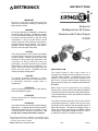
Protect•ir
Multispectrum IR Flame
Detector with Pulse Output
X3300
DESCRIPTION
The X3300 Protect•ir with pulse output is a
multispectrum infrared (IR) flame detector for use in
controller based systems. In addition to use in new
systems, it can serve as a direct field replacement for
Det-Tronics controller based flame detectors that
generate a pulse output (not compatible with R7484 and
R7409B/C).
When used as a field replacement, all operating
features of the current controller are retained in addition
to gaining the advanced features of the X3300 detector.
In typical applications, the four wire X3300 can utilize all
existing system wiring.
The X3300 contains three IR sensors and provides
unsurpassed detection of flames from light to heavy
hydrocarbon fuels combined with the highest degree of
false alarm rejection. The detector is suitable for use in
indoor and outdoor applications with NEMA 4X/IP66
classifications. Models are available for ‘EEx d e’, ‘EEx d’
or Class I/II/III, Division 1/2 hazardous locations.
*o i is Detector Electronics' Trademark for its patented Optical
Integrity Systems, U.S. Patent 3,952,196, United Kingdom Patent
1,534,969, Canada Patent 1,059,598.
©Detector Electronics Corporation 2000
12/00
95-8517
be bypassed during welding operations in situations
where the possibility of a false alarm cannot be
tolerated. Gas welding mandates system bypass, since
the gas torch is an actual fire. Arc welding rods can
contain organic binder materials in the flux that burn
during the welding operation and are detectable by the
X3300. Welding rods with clay binders do not burn and
will not be detected by the X3300. However, system
bypass is always recommended, since the material
being welded may be contaminated with organic
substances (paint, oil, etc.) that will burn and possibly
trigger the X3300.
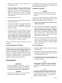
Table 1—Detector Status Indicator
Detector Status
LED Indicator
Power On/Normal Operation
(no fault or fire alarm)
Green
Fault
Yellow
Fire (Alarm)
Red
Medium Sensitivity
Two Yellow Flashes
During Power-up
Very High Sensitivity
Four Yellow Flashes
During Power-up
Artificial Lighting
The X3300 should not be located within 3 feet of
artificial lights. Artificial lights should not be positioned
so that they are pointed directly at the detector.
A tricolor LED on the detector faceplate indicates
normal, fire alarm, and fault conditions. Table 1
indicates the condition of the LED for each detector
status. The LED is non-latching.
EMI/RFI Interference
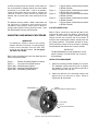
The X3300 is available in aluminum or stainless steel
and features multiple mounting options, including:
• Direct to flexible conduit with the use of a Q9001L
swivel mount
The X3300 is resistant to interference by EMI and RFI,
and is EMC Directive compliant. It will not respond to a
5 watt walkie-talkie at distances greater than 1 foot. Do
not operate a walkie-talkie within 1 foot of the X3300.
• Direct to conduit elbow mount.
Non-Carbon Fires
GENERAL APPLICATION
INFORMATION
The X3300 is a multiple spectrum IR device with
detection limited to carbonaceous fuels. It should not
be used to detect fires that do not contain carbon, such
as hydrogen, sulfur and burning metals.
RESPONSE CHARACTERISTICS
Response is dependent on the type of fuel, the
temperature of the fuel, and the time required for the fire
to come to equilibrium. As with all fire tests, results
must be interpreted according to an individual
application.
INSTALLATION
DETECTOR POSITIONING
Detectors should be positioned to provide the best
unobstructed view of the area to be protected. The
following factors should also be taken into consideration:
See Appendix A for fire test results.
• Identify all high risk fire ignition sources.
IMPORTANT APPLICATION CONSIDERATIONS
• Be sure that enough detectors are used to adequately
cover the hazardous area.
In applying any type of sensing device as a fire
detector, it is important to know of any conditions that
can prevent the device from responding to fire, and also
to know what other sources besides fire can cause the
device to respond.
• Locate and position the detector so that the fire
hazard(s) are within both the field of view and
detection range of the device. Refer to Appendix A
for specific information.
Welding
• Be sure that the unit is easily accessible for cleaning
and other periodic servicing.
Arc welding should not be performed within 40 feet of
the very high sensitivity detector (10 feet for medium
sensitivity detector). It is recommended that the system
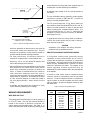
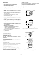
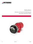
• For outdoor applications, the detector should be
aimed downward at least 10 to 20 degrees to allow
lens openings to drain. See Figure 1. The detector
2
output detectors, the wiring and power supplies may not
be adequate. Consult the factory for assistance.
CENTER AXIS
OF DETECTOR
FIELD OF VIEW
A minimum input voltage of 18 vdc must be present at
the X3300.
The use of shielded cable is required to protect against
interference caused by EMI and RFI. Consult the
factory if not using shielded cable.
INCORRECT
The “B” (pulse output) and “D” (oi driver) leads from
each detector should be shielded from the “B” and “D”
leads of all other detectors in order to prevent false
alarms resulting from crosstalk between zones. It is
recommended that the “A” and “C” leads also be
shielded to provide maximum immunity to EMI/RFI.
(See Figures 6 to 10.)
CENTER AXIS
OF DETECTOR
FIELD OF VIEW
B1974
CORRECT
In applications where the wiring cable is installed in
conduit, the conduit should not be used for wiring to
other electrical equipment.
NOTE: DETECTOR MUST ALWAYS BE AIMED
DOWNWARD AT LEAST 10 TO 20 DEGREES.
Figure 1—Detector Orientation Relative to Horizon
CAUTION
Installation of the detector and wiring should be
performed only by qualified personnel.
should be positioned so that its field of view does not
cover areas outside the hazardous area. This will
minimize the possibility of false alarms caused by
activities outside the area requiring protection.
PROTECTION AGAINST MOISTURE DAMAGE
It is important to take proper precautions during
installation to ensure that moisture will not come in
contact with the electrical connections or components
of the system. The wiring pigtail for the X3300 is factory
sealed for easy installation onto a junction box where
electrical connections are made. The integrity of the
system regarding moisture protection must be
maintained for proper operation and is the responsibility
of the installer.
• For best performance, the detector should be
mounted on a rigid surface in a low vibration area.
• Dense fog, rain or ice can absorb IR radiation and
reduce the sensitivity of the detector.
• Although IR detectors are less affected by smoke than
other detectors, the X3300 should not be placed
where rising combustion products can obscure its
vision. If smoke is expected before fire, smoke or
other alternative detectors should be used in
conjunction with the X3300. For indoor applications, if
dense smoke is expected to accumulate at the onset
of a fire, mount the detector on a side wall at least a
few feet (approximately 1 meter) down from the
ceiling.
If conduit is used, drains must be installed at water
collection points to automatically drain accumulated
moisture. Conduit breathers should be installed at
upper locations to provide ventilation and allow water
vapor to escape. At least one breather should be used
with each drain.
• If possible, fire tests should be conducted to verify
correct detector positioning and coverage.
Table 2—Detector Wiring Requirements
WIRING REQUIREMENTS
WIRE SIZE AND TYPE
The system should be wired using a 14 to 22 gauge (1.3
to 0.5 mm2) cable. The wire size selected should be
based on the number of detectors connected, the
supply voltage and the cable length. See Table 2. In
some cases where the X3300 is replacing existing pulse
3
Wire Size
AWG
Minimum Voltage
at Controller
22
22
18
18
16
16
14
14
23 VDC
20.5 VDC
22 VDC
20 VDC
23 VDC
20.5 VDC
21.5 VDC
20 VDC
Maximum Distance
Feet
Meters
500
250
1000
500
2000
1000
2000
1000
152
76
305
152
610
305
610
305
95-8517
Conduit raceways should be inclined so that water will
flow to low points for drainage and will not collect inside
enclosures or on conduit seals. If this is not possible,
install conduit drains above the seals to prevent the
collection of water or install a drain loop below the
detector with a conduit drain at the lowest point of the
loop.
Figure 6 –
The detector is factory sealed. While conduit seals are
not required for compliance with explosion-proof
installation requirements, steps must be taken to
prevent water ingress into the junction box area. Units
with M25 threads must use an IP66 washer.
Figure 10 –
Figure 7 –
Figure 8 –
Figure 9 –
A Typical System, X3300 Detectors Wired
to R7404 Controller
A Typical System, X3300 Detectors Wired
to R7404 Star Logic Controller
A Typical System, X3300 Detectors Wired
to R7494 Controller
A Typical System, X3300 Detectors Wired
to R7495 Controller
A Typical System, X3300 Detectors Wired
to R7405 Controller
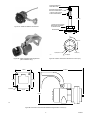
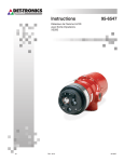
oi PLATE ORIENTATION
Refer to Figure 2 and insure that the oi plate will be
oriented as shown when the X3300 is mounted and
sighted. This will ensure proper operation of the oi
system and will also minimize the accumulation of
moisture and contaminants between the oi plate and
the viewing windows. The oi plate includes an arrow,
which should be pointed in the up direction, indicating
that the oi plate and detector are correctly oriented.
MOUNTING AND WIRING PROCEDURE
IMPORTANT
If installing an X3300 in place of an existing
detector, be sure to move the “A” Lead (detector
power) at the controller from the +290 VDC
source to the +24 VDC source. Do not apply
290 VDC to the X3300.
IMPORTANT
The oi plate must be securely tightened to ensure
proper operation of the oi system (40 oz./inches
recommended).
Refer to the procedure below and the listed figures to
mount and wire the X3300.
INSTALLATION PROCEDURE
Figure 1 –
Figure 2 –
Figure 3A/B –
Figure 4A/B –
Figure 5A/B –
Detector Orientation Relative to Horizon
Front View of the X3300 Detector
X3300 Mounting Options
Mounting Bracket Dimensions
X3300 Wiring Identification
VIEWING WINDOW (3)
1.
Install the mounting bracket assembly on the wall.
The installation surface should be free of vibration
and suitable to receive 1/4 inch (M6) screws with a
length of at least 1 inch (25 mm).
2.
Attach the detector to the mounting bracket and
tighten the nut to secure it in place. Refer to
Figures 3A, 3B, 4A and 4B.
oi ARROW
(MUST BE ORIENTED WITH ARROW POINTING UP)
oi PLATE KNOB
oi PLATE
DETECTOR STATUS INDICATOR
A1926
Figure 2—Front View of the X3300 Detector
4
DETECTOR SCREWS ONTO
SWIVEL MOUNT HERE
3/4 INCH NUT USED TO SECURE
DETECTOR TO SWIVEL MOUNT
1/2 INCH NUT USED TO ADJUST
ELBOW TO DESIRED ANGLE
5-1/4 (133)
1-3/8 INCH NUT USED TO ROTATE
SWIVEL/DETECTOR ASSEMBLY
TO DESIRED POSITION
Figure 3A—X3300 with Q9001L Swivel Mount
MOUNTING BASE
2-1/2 (64)
3X 120° ± 2°
3X 0.25 (6.4)
2.0 (50.8) DIA.
B1467
Figure 4A—Q9001L Swivel Mount Dimensions in Inches (mm)
Figure 3B—X3300 with Q9033 Mounting Bracket
(EExe Installation Only)
3.9 (9.9)
3.0 (7.6)
2–1/2 (64) DIA.
10.7 (27.2)
3.9 (9.9)
0.4 (1.0) DIA.
3.0 (7.6)
7.8 (19.8)
A1981
Figure 4B—Dimensions of X3300 with Q9033 Mounting Bracket in Inches (cm)
5
95-8517
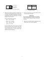
DC + ("A" LEAD)
TERMINAL NO.
FUNCTION
BLACK
DC – ("C" LEAD)
1
DC+ ("A" LEAD)
WHITE
SIGNAL ("B" LEAD)
2
SIGNAL ("B" LEAD)
3
DC– ("C" LEAD)
4
Oi ("D" LEAD)
RED
X3300
GREEN
A2010
Oi ("D" LEAD)
A2023
Figure 5A—Wiring Identification for X3300 with Pigtails
Figure 5B—Terminal Identification for X3300
with Integral Junction Box
3.
Make the field wiring connections following local
ordinances and the guidelines in this manual. Refer
to Figures 5A and 5B for identification of detector
wires/terminals and Figures 6 through 10 for wiring
diagrams of typical systems.
4.
IMPORTANT
Do not test any wiring connected to the detector
with a meg-ohmmeter. Disconnect wiring at the
detector before checking system wiring for
continuity.
Wire the X3300 Detector as follows:
Red–
Check all field wiring to be sure that the proper
connections have been made.
DC + (“A” Lead)
Black– DC – (“C” Lead)
5.
White– Signal (“B” Lead)
Green– Oi (“D” Lead)
Leave the shield open at the detector end and
permanently isolate it from accidental contact with
the case and/or other conductors. Connect the
shield to power minus (–) at the controller end.
(Refer to Figures 6 through 10.)
6
Make the final detector sighting adjustments and
ensure that the swivel mount is tightened.
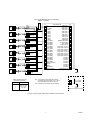
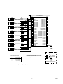
NOTE: DO NOT CONNECT THE X3300 "A" LEAD (RED) TO
TERMINAL J1-3 (290 VDC).
RED
BLACK
WHITE
GREEN
RED
BLACK
X3300
WHITE
GREEN
DETECTOR 1
RED
BLACK
WHITE
GREEN
RED
BLACK
X3300
WHITE
GREEN
J1-5
J1-13
DETECTOR 2
RED
BLACK
WHITE
GREEN
RED
BLACK
X3300
WHITE
GREEN
J1-6
J1-14
DETECTOR 3
RED
BLACK
WHITE
GREEN
RED
BLACK
X3300
WHITE
GREEN
J1-7
J1-15
DETECTOR 4
RED
BLACK
WHITE
GREEN
RED
BLACK
X3300
WHITE
GREEN
J1-8
J1-16
DETECTOR 5
RED
BLACK
WHITE
GREEN
RED
BLACK
X3300
WHITE
GREEN
J1-9
J1-17
DETECTOR 6
RED
BLACK
WHITE
GREEN
RED
BLACK
X3300
WHITE
GREEN
J1-10
J1-18
DETECTOR 7
RED
BLACK
WHITE
GREEN
RED
BLACK
X3300
WHITE
GREEN
24
VDC
J1
+
1
–
2
+
–
3
J2
R7404 CONTROLLER
ZONE OUTPUT 1
33
ZONE OUTPUT 2
34
(A) +290 VDC
ZONE OUTPUT 3
35
4
B - INPUT 1
ZONE OUTPUT 4
36
5
B - INPUT 2
ZONE OUTPUT 5
37
6
B - INPUT 3
ZONE OUTPUT 6
38
7
B - INPUT 4
ZONE OUTPUT 7
39
8
B - INPUT 5
ZONE OUTPUT 8
40
9
B - INPUT 6
FIRE LOGIC “A”
41
10
B - INPUT 7
FIRE LOGIC “B”
42
11
B - INPUT 8
ALARM OUTPUT
43
12
D1-1 oi DRIVER
EXTERNAL RESET/INHIBIT
44
13
D1-2 oi DRIVER
OUTPUTS INHIBITED
45
14
D1-3 oi DRIVER
FAULT OUTPUT
46
15
D1-4 oi DRIVER
EXTERNAL ACCEPT
47
16
D1-5 oi DRIVER
STATUS & DET. OUTPUT S1
48
17
D1-6 oi DRIVER
STATUS & DET. OUTPUT S2
49
18
D1-7 oi DRIVER
STATUS & DET. OUTPUT S3
50
19
D1-8 oi DRIVER
STATUS & DET. OUTPUT S4
51
20
D2-1 oi DRIVER
STATUS & DET. OUTPUT S5
52
21
D2-2 oi DRIVER
STATUS & DET. OUTPUT S6
53
22
D2-3 oi DRIVER
STATUS & DET. OUTPUT S7
54
23
D2-4 oi DRIVER
STATUS & DET. OUTPUT S8
55
24
D2-5 oi DRIVER
DATA BUS 0
56
25
D2-6 oi DRIVER
DATA BUS 1
57
26
D2-7 oi DRIVER
DATA BUS 2
58
27
D2-8 oi DRIVER
DATA BUS 3
59
28
DMA OUT AVAILABLE
DATA BUS 4
60
29
DMA OUT
DATA BUS 5
61
30
DMA IN
DATA BUS 6
62
31
DATA STROBE
DATA BUS 7
63
32
DMA IN AVAILABLE
} 10 TO 38 VDC
CHASSIS (EARTH) GND
64
A2009
J1-11
J1-19
DETECTOR 8
TO J1-2
TERMINAL IDENTIFICATION FOR X3300
WITH INTEGRAL JUNCTION BOX.
TERMINAL NO.
FUNCTION
1
DC+ ("A" LEAD)
2
SIGNAL ("B" LEAD)
3
DC– ("C" LEAD)
4
Oi ("D" LEAD)
NOTE: IF THE POWER SUPPLY MINUS CANNOT BE CONNECTED
TO CHASSIS (EARTH) GROUND, CONNECT A 0.47 µF 250 VDC
NON-POLARIZED CAPACITOR BETWEEN J1-2 AND J2-64.
62
63
0.47 µF / 250 VDC
NON-POLARIZED
64
NOTE: 2.5 AMPERES @ 24 VDC REQUIRED PER EIGHT DETECTORS.
GROUND FAULT PROTECTED SYSTEMS
Figure 6—A Typical System, X3300 Detectors Wired to R7404 Controller
7
95-8517
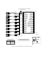
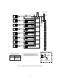
NOTE: DO NOT CONNECT THE X3300 "A" LEAD (RED) TO
TERMINAL J1-3 (290 VDC).
RED
BLACK
WHITE
GREEN
RED
BLACK
X3300
WHITE
GREEN
24
VDC
J1
+
1
+24 VDC
ZONE OUTPUT 1
33
–
2
CIRCUIT GROUND
ZONE OUTPUT 2
34
3
+290 VDC
ZONE OUTPUT 3
35
4
B1 - INPUT SIGNAL
ZONE OUTPUT 4
36
5
B2 - INPUT SIGNAL
ZONE OUTPUT 5
37
6
B3 - INPUT SIGNAL
ZONE OUTPUT 6
38
7
B4 - INPUT SIGNAL
ZONE OUTPUT 7
39
8
B5 - INPUT SIGNAL
ZONE OUTPUT 8
40
9
B6 - INPUT SIGNAL
FIRE LOGIC “A”
41
10
B7 - INPUT SIGNAL
FIRE LOGIC “B”
42
11
B8 - INPUT SIGNAL
ALARM OUTPUT
43
12
D1 oi DRIVER
EXTERNAL RESET/INHIBIT
44
13
D2 oi DRIVER
OUTPUTS INHIBITED
45
14
D3 oi DRIVER
FAULT OUTPUT
46
15
D4 oi DRIVER
EXTERNAL ACCEPT
47
16
D5 oi DRIVER
STATUS & DET. OUTPUT S1
48
17
D6 oi DRIVER
STATUS & DET. OUTPUT S2
49
18
D7 oi DRIVER
STATUS & DET. OUTPUT S3
50
19
D8 oi DRIVER
STATUS & DET. OUTPUT S4
51
20
DATA BUS OUT
STATUS & DET. OUTPUT S5
52
21
DATA BUS OUT
STATUS & DET. OUTPUT S6
53
22
DATA BUS OUT
STATUS & DET. OUTPUT S7
54
23
DATA BUS OUT
STATUS & DET. OUTPUT S8
55
24
DATA BUS OUT
DATA BUS 0
56
25
DATA BUS OUT
DATA BUS 1
57
26
DATA BUS OUT
DATA BUS 2
58
27
DATA BUS OUT
DATA BUS 3
59
28
NOT USED
DATA BUS 4
60
29
NOT USED
DATA BUS 5
61
30
DATA STROBE IN
DATA BUS 6
62
31
NOT USED
DATA BUS 7
63
32
NOT USED
EARTH GROUND
DETECTOR 1
RED
BLACK
WHITE
GREEN
RED
BLACK
X3300
WHITE
GREEN
J1-5
J1-13
DETECTOR 2
RED
BLACK
WHITE
GREEN
RED
BLACK
X3300
WHITE
GREEN
J1-6
J1-14
DETECTOR 3
RED
BLACK
WHITE
GREEN
RED
BLACK
X3300
WHITE
GREEN
J1-7
J1-15
DETECTOR 4
RED
BLACK
WHITE
GREEN
RED
BLACK
X3300
WHITE
GREEN
J1-8
J1-16
DETECTOR 5
RED
BLACK
WHITE
GREEN
RED
BLACK
X3300
WHITE
GREEN
J1-9
J1-17
DETECTOR 6
RED
BLACK
WHITE
GREEN
RED
BLACK
X3300
WHITE
GREEN
J1-10
J1-18
DETECTOR 7
J2
R7404 STAR LOGIC CONTROLLER
64
A2016
X3300
RED
BLACK
WHITE
GREEN
RED
BLACK
WHITE
GREEN
J1-11
J1-19
DETECTOR 8
TO J1-2
TERMINAL IDENTIFICATION FOR X3300
WITH INTEGRAL JUNCTION BOX.
TERMINAL NO.
FUNCTION
1
DC+ ("A" LEAD)
2
SIGNAL ("B" LEAD)
3
DC– ("C" LEAD)
4
Oi ("D" LEAD)
NOTE: IF THE POWER SUPPLY MINUS CANNOT BE CONNECTED
TO CHASSIS (EARTH) GROUND, CONNECT A 0.47 µF 250 VDC
NON-POLARIZED CAPACITOR BETWEEN J1-2 AND J2-64.
62
63
0.47 µF / 250 VDC
NON-POLARIZED
64
NOTE: 2.5 AMPERES @ 24 VDC REQUIRED PER EIGHT DETECTORS.
GROUND FAULT PROTECTED SYSTEMS
Figure 7—A Typical System, X3300 Detectors Wired to R7404 Star Logic Controller
8
RED
BLACK
WHITE
GREEN
RED
BLACK
X3300
WHITE
GREEN
DETECTOR 1
RED
BLACK
WHITE
GREEN
RED
BLACK
X3300
WHITE
GREEN
J1-5
J1-13
DETECTOR 2
RED
BLACK
WHITE
GREEN
RED
BLACK
X3300
WHITE
GREEN
J1-6
J1-14
DETECTOR 3
X3300
RED
BLACK
WHITE
GREEN
RED
BLACK
WHITE
GREEN
J1-7
J1-15
DETECTOR 4
RED
BLACK
WHITE
GREEN
RED
BLACK
X3300
WHITE
GREEN
J1-8
J1-16
DETECTOR 5
RED
BLACK
WHITE
GREEN
RED
BLACK
X3300
WHITE
GREEN
J1-9
J1-17
DETECTOR 6
RED
BLACK
WHITE
GREEN
RED
BLACK
X3300
WHITE
GREEN
J1-10
J1-18
DETECTOR 7
24
VDC
J1
+
1
+24 VDC
ZONE OUTPUT 1
33
–
2
CIRCUIT GROUND
ZONE OUTPUT 2
34
3
+24 VDC
ZONE OUTPUT 3
35
4
B1 - INPUT SIGNAL
ZONE OUTPUT 4
36
5
B2 - INPUT SIGNAL
ZONE OUTPUT 5
37
6
B3 - INPUT SIGNAL
ZONE OUTPUT 6
38
7
B4 - INPUT SIGNAL
ZONE OUTPUT 7
39
8
B5 - INPUT SIGNAL
ZONE OUTPUT 8
40
9
B6 - INPUT SIGNAL
FIRE LOGIC “A”
41
10
B7 - INPUT SIGNAL
FIRE LOGIC “B”
42
11
B8 - INPUT SIGNAL
ALARM OUTPUT
43
12
D1 oi DRIVER
EXTERNAL RESET/INHIBIT
44
13
D2 oi DRIVER
OUTPUTS INHIBITED
45
14
D3 oi DRIVER
FAULT OUTPUT
46
15
D4 oi DRIVER
EXTERNAL ACCEPT
47
16
D5 oi DRIVER
STATUS & DET. OUTPUT S1
48
17
D6 oi DRIVER
STATUS & DET. OUTPUT S2
49
18
D7 oi DRIVER
STATUS & DET. OUTPUT S3
50
19
D8 oi DRIVER
STATUS & DET. OUTPUT S4
51
20
DATA BUS OUT
STATUS & DET. OUTPUT S5
52
21
DATA BUS OUT
STATUS & DET. OUTPUT S6
53
22
DATA BUS OUT
STATUS & DET. OUTPUT S7
54
23
DATA BUS OUT
STATUS & DET. OUTPUT S8
55
24
DATA BUS OUT
DATA BUS 0
56
25
DATA BUS OUT
DATA BUS 1
57
26
DATA BUS OUT
DATA BUS 2
58
27
DATA BUS OUT
DATA BUS 3
59
28
NOT USED
DATA BUS 4
60
29
NOT USED
DATA BUS 5
61
30
DATA STROBE IN
DATA BUS 6
62
31
NOT USED
DATA BUS 7
63
32
NOT USED
EARTH GROUND
J2
R7494 CONTROLLER
64
A2012
X3300
RED
BLACK
WHITE
GREEN
RED
BLACK
WHITE
GREEN
J1-11
J1-19
DETECTOR 8
TO J1-2
TERMINAL IDENTIFICATION FOR X3300
WITH INTEGRAL JUNCTION BOX.
TERMINAL NO.
FUNCTION
1
DC+ ("A" LEAD)
2
SIGNAL ("B" LEAD)
3
DC– ("C" LEAD)
4
Oi ("D" LEAD)
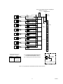
NOTE: IF THE POWER SUPPLY MINUS CANNOT BE CONNECTED
TO CHASSIS (EARTH) GROUND, CONNECT A 0.47 µF 250 VDC
NON-POLARIZED CAPACITOR BETWEEN J1-2 AND J2-64.
62
NOTE: 2.5 AMPERES @ 24 VDC REQUIRED PER EIGHT DETECTORS.
64
63
0.47 µF / 250 VDC
NON-POLARIZED
GROUND FAULT PROTECTED SYSTEMS
Figure 8—A Typical System, X3300 Detectors Wired to R7494 Controller
9
95-8517
R7495 CONTROLLER
RED
BLACK
WHITE
GREEN
RED
BLACK
X3300
WHITE
GREEN
24
VDC
J1
+
1
+24 VDC
–
2
GROUND
3
DETECTOR 1
RED
BLACK
WHITE
GREEN
RED
BLACK
X3300
WHITE
GREEN
J2-44
J2-36
4
J2
5
31
32
DETECTOR 2
X3300
RED
BLACK
WHITE
GREEN
RED
BLACK
WHITE
GREEN
33
34
J2-45
J2-37
DETECTOR 3
X3300
RED
BLACK
WHITE
GREEN
RED
BLACK
WHITE
GREEN
J2-46
J2-38
DETECTOR 4
RED
BLACK
WHITE
GREEN
RED
BLACK
X3300
WHITE
GREEN
J2-47
J2-39
DETECTOR 5
RED
BLACK
WHITE
GREEN
RED
BLACK
X3300
WHITE
GREEN
J2-48
J2-40
35
D1
36
D2
37
D3
38
D4
39
D5
40
D6
41
D7
42
D8
43
B1
44
B2
45
B3
46
B4
DETECTOR 6
RED
BLACK
WHITE
GREEN
RED
BLACK
X3300
WHITE
GREEN
J2-49
J2-41
DETECTOR 7
X3300
RED
BLACK
WHITE
GREEN
RED
BLACK
WHITE
GREEN
J2-50
J2-42
DETECTOR 8
47
B5
48
B6
49
B7
50
B8
A2011
TO J1-2
TERMINAL IDENTIFICATION FOR X3300
WITH INTEGRAL JUNCTION BOX.
TERMINAL NO.
FUNCTION
1
DC+ ("A" LEAD)
2
SIGNAL ("B" LEAD)
3
DC– ("C" LEAD)
4
Oi ("D" LEAD)
NOTE: IF THE POWER SUPPLY MINUS CANNOT BE CONNECTED
TO CHASSIS (EARTH) GROUND, CONNECT A 0.47 µF 250 VDC
NON-POLARIZED CAPACITOR BETWEEN J1-2 AND J1-5.
3
NOTE: 2.5 AMPERES @ 24 VDC REQUIRED PER EIGHT DETECTORS.
4
0.47 µF / 250 VDC
NON-POLARIZED
5
GROUND FAULT PROTECTED SYSTEMS
Figure 9—A Typical System, X3300 Detectors Wired to R7495 Controller
10
NOTE: DO NOT CONNECT THE X3300 "A" LEAD (RED) TO
TERMINAL J2-34 (290 VDC).
R7405 CONTROLLER
RED
BLACK
WHITE
GREEN
RED
BLACK
X3300
WHITE
GREEN
24
VDC
J1
+
1
+24 VDC
–
2
GROUND
3
DETECTOR 1
RED
BLACK
WHITE
GREEN
RED
BLACK
X3300
WHITE
GREEN
J2-44
J2-36
4
J2
5
31
32
DETECTOR 2
X3300
RED
BLACK
WHITE
GREEN
RED
BLACK
WHITE
GREEN
33
J2-45
J2-37
DETECTOR 3
X3300
RED
BLACK
WHITE
GREEN
RED
BLACK
WHITE
GREEN
J2-46
J2-38
DETECTOR 4
RED
BLACK
WHITE
GREEN
RED
BLACK
X3300
WHITE
GREEN
J2-47
J2-39
DETECTOR 5
RED
BLACK
WHITE
GREEN
RED
BLACK
X3300
WHITE
GREEN
J2-48
J2-40
34
+290 VDC
35
D1
36
D2
37
D3
38
D4
39
D5
40
D6
41
D7
42
D8
43
B1
44
B2
45
B3
46
B4
47
B5
48
B6
49
B7
50
B8
DETECTOR 6
RED
BLACK
WHITE
GREEN
RED
BLACK
X3300
WHITE
GREEN
J2-49
J2-41
DETECTOR 7
RED
BLACK
WHITE
GREEN
RED
BLACK
X3300
WHITE
GREEN
J2-50
J2-42
DETECTOR 8
A2015
TO J1-2
TERMINAL IDENTIFICATION FOR X3300
WITH INTEGRAL JUNCTION BOX.
TERMINAL NO.
FUNCTION
1
DC+ ("A" LEAD)
2
SIGNAL ("B" LEAD)
3
DC– ("C" LEAD)
4
Oi ("D" LEAD)
NOTE: IF THE POWER SUPPLY MINUS CANNOT BE CONNECTED
TO CHASSIS (EARTH) GROUND, CONNECT A 0.47 µF 250 VDC
NON-POLARIZED CAPACITOR BETWEEN J1-2 AND J1-5.
3
NOTE: 2.5 AMPERES @ 24 VDC REQUIRED PER EIGHT DETECTORS.
4
0.47 µF / 250 VDC
NON-POLARIZED
5
GROUND FAULT PROTECTED SYSTEMS
Figure 10—A Typical System, X3300 Detectors Wired to R7405 Controller
11
95-8517
OPTICAL INTEGRITY (oi)
COUNT TEST MODE
The X3300 includes the Automatic Optical Integrity (oi)
feature — a calibrated performance test that is
automatically performed once per minute to verify
complete detector operation capabilities. No testing
with an external test lamp is required. The detector
automatically performs the same test that a
maintenance person with a test lamp would perform —
once every minute, 60 times per hour. A successful
automatic oi test does not produce an alarm condition.
The detector can be tested using the Count Test mode.
When in the Count Test mode, the frequency of the
digital pulses from the detector is displayed in the
ZONE and DETECTOR indicators on the controller
faceplate. The Count Test mode may be used to check
the oi signal strength, the signal (cps) from a test fire, or
false alarm source. This can be useful during system
set-up for sensitivity and time delay settings. This test is
performed in the following manner:
The Protect•ir signals a fault condition when less than
50% of the detection range remains, as determined by
three consecutive oi checks. This is indicated by the
amber color of the LED on the face of the detector. See
the “Troubleshooting” section for further information.
1.
Place the keylock switch in the TEST position.
2.
Simultaneously press and release the SELECT and
TEST buttons. The Status display will change from
a “1” to an “8” indicating that the controller is in the
Count Test mode of operation.
STARTUP PROCEDURE
3.
Press the SELECT button until the desired zone is
displayed in the ZONE indicator on the controller
front panel.
4.
Press and hold the TEST button to energize the oi
source lamps for the selected detector. The
DETECTOR/ZONE display indicates the counts per
second (cps) received from the detector. If the
counts per second exceeds 99, the FIRE LOGIC
LEDs are illuminated to indicate that the number
shown on the display must be multiplied by 10.
The normal reading for an oi test is 100 cps. For
a live fire test, 300 cps will be generated.
When installation of the equipment is complete, perform
the “Manual oi Test” and/or “Count Test Mode” below.
Allow 20 to 30 minutes for the detector optics to reach
equilibrium. Housing will be warm to the touch.
MANUAL Oi TEST
1.
Place the keylock switch in the TEST position.
2.
Press the SELECT button to display the desired
zone on the ZONE indicator on the front panel of the
controller.
3.
A zero reading may indicate a dirty window, oi problem,
faulty detector or defective wiring.
Press and hold the TEST button to energize the test
lamps for the selected detector. The ZONE
OUTPUT LED for the tested zone flashes and the
SYSTEM STATUS display indicates a “6” (fire
condition) if the test is successful.
4.
Release the TEST button. The ZONE OUTPUT LED
for the tested zone should remain on steadily.
5.
Return to step 2 to test next detector.
Release the Test button, the ZONE and DETECTOR
display should drop to a reading of 0 to 1 counts per
second.
TROUBLESHOOTING
WARNING
The detector contains no user serviceable
components and should never be opened.
If the system responds differently than indicated
above, proceed with the count test for the problem
zone to verify detector and wiring operation.
NOTE
Since the entire unit must be returned to the
factory for repair, it is highly recommended that a
complete spare be kept on hand for field
replacement to ensure continuous protection.
12
1.
Disable any extinguishing equipment that is
connected to the unit.
2.
Inspect the viewing windows for contamination and
clean as necessary. The detector is relatively
insensitive to airborne contaminants, however, thick
deposits of ice, dirt, or oil will reduce sensitivity.
(Refer to the “Maintenance” section for complete
information regarding cleaning of the detector
viewing window.)
3.
Check input power to the unit.
4.
If the fire system has a logging function, check the
fire panel log for status.
5.
Turn off the input power to the detector and check
all wiring for continuity. Important: Disconnect
wiring at the detector before checking system
wiring for continuity.
6.
To maintain maximum sensitivity, the viewing windows
of the X3300 must be kept relatively clean. Refer to the
procedure below for instructions.
CLEANING PROCEDURE
CAUTION
Disable any extinguishing equipment that is
connected to the unit to prevent unwanted
actuation.
To clean the window and o i plate, use Det-Tronics
window cleaner (part number 001680-001) and a soft
cloth or tissue and refer to the procedure below.
If all wiring checks out and cleaning of the o i
plate/window did not correct the fault condition,
check for high levels of background IR radiation by
covering the detector with the factory supplied
cover or aluminum foil. If the fault condition clears
within 6 minutes or less, extreme background IR is
present. Re-adjust the view of the detector away
from the IR source or relocate the detector.
1.
Disable any extinguishing equipment that is
connected to the unit.
2.
Since the X3300 is less affected by contamination
than other detectors, removal of the o i plate is
needed only under extreme conditions. In addition,
it is not necessary to achieve perfect cleanliness,
because IR is not significantly absorbed by slight
films of oil and/or salt. If a fault condition is still
indicated after cleaning, remove and clean the oi
plate using the procedure below.
3.
Clean all three viewing windows and reflector
surfaces thoroughly using a clean cloth, cotton
swab or tissue and Det-Tronics window cleaning
solution. If a stronger solution is needed, isopropyl
alcohol may be used.
If none of these actions corrects the problem, contact
the factory.
PERIODIC CHECKOUT PROCEDURE
Oi PLATE REMOVAL
Periodic testing is not required when the detector is
configured for automatic optical integrity testing. If the
X3300 is configured for manual o i operation, a
checkout of the system using the oi feature should be
performed on a regularly scheduled basis to ensure that
the system is operating properly. To test the system,
perform the “Manual o i Test” as described in the
“Startup Procedure” section of this manual.
1.
Remove the oi plate from the detector by loosening
the oi plate knob.
2.
Thoroughly clean the oi plate reflective surfaces,
holding it by its edges to avoid leaving fingerprints
on the inside reflective surface.
3.
Re-install the oi plate. Ensure that the plate is flat
on the detector surface. Tighten the oi plate knob
securely (40 oz/inches).
MAINTENANCE
NOTE
If the oi plate is removed, be sure to install the
original oi plate. oi plates are not interchangeable
and should not be mixed with oi plates from other
detectors.
IMPORTANT
Periodic flamepath inspections are not
recommended since the product is not intended to
be serviced and provides proper ingress protection
to eliminate potential deterioration of the flamepaths.
NOTE
If corrosive contaminants in the atmosphere cause
the oi plate surface to deteriorate to the extent that
it is no longer possible to restore it to its original
condition, it must be replaced. Consult factory for
oi plate replacement procedure.
WARNING
The detector contains no user serviceable
components and should never be opened.
13
95-8517
FEATURES
HUMIDITY RANGE—
0 to 95% relative humidity, can withstand 100%
condensing humidity for short periods of time.
• Long detection range to carbonaceous fires.
• Unequaled false alarm rejection.
DIMENSIONS—
See Figures 11A and 11B.
• Responds to a fire in the presence of modulated
blackbody radiation (i.e. heaters, ovens, turbines)
without false alarm.
• Heated optics for increased resistance to moisture
and ice.
3.23 (82.04)
• Factory sealed device eliminates need for explosionproof conduit seal.
4.08 (103.6)
• Automatic and manual optical integrity (oi) test.
• Easily replaceable oi plate.
• Tricolor LED indicates normal operation, fire and fault
conditions.
• Multiple mounting options include mounting directly
onto most junction boxes using a simple adapter, or
the use of a swivel union or swivel mount available
from Det-Tronics.
3.23 (82.04)
3.68 (93.5)
• Operates under adverse weather conditions and in
dirty environments.
• Hazardous location capabilities:
- Explosion-proof/flame-proof detector housing.
CSA, FM and CENELEC Certified.
- Models available with CENELEC Certified EEx d e.
0.76 (19.3)
A1941
Figure 11A—Dimensions of Standard X3300 in Inches (mm)
• Class A wiring per NFPA-72.
• 5 year warranty.
3.23 (82.04)
SPECIFICATIONS
4.08 (103.6)
OPERATING VOLTAGE—
24 volts dc nominal (18 vdc minimum, 32 vdc
maximum).
3.23 (82.04)
POWER CONSUMPTION—
7.5 watts at 24 volts dc nominal; 9.0 watts at 32 volts dc
maximum.
POWER UP TIME—
Fault indication clears after 0.5 second; device is ready
to indicate an alarm condition after 30 seconds.
7.4 (188)
TEMPERATURE RANGE—
Operating:
–40°F to +167°F (–40°C to +75°C).
Storage:
–67°F to +185°F (–55°C to +85°C).
Hazardous location ratings from -55°C to +125°C
available on extended temperature model.
A1982
Figure 11B—Dimensions of X3300 with Integral
Junction Box in Inches (mm)
14
WIRING—
14 AWG (1.5 mm 2 ) to 22 AWG (0.3 mm 2 ) shielded
cable is recommended.
Important: 18 vdc minimum must be available at the
detector.
RESPONSE TIME—
Typical response times are under 10 seconds. Models
are available that can respond to automotive paint gun
fires in under 0.5 seconds. See Appendix A for actual
response times.
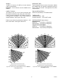
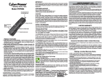
CONE OF VISION—
The detector has a 90° cone of vision (horizontal) with
the highest sensitivity lying along the central axis.
Unlike conventional detectors, the X3300 provides full
coverage at a minimum of 70% of the maximum
detection distance. See Figures 12A to 12K.
ENCLOSURE MATERIAL—
Aluminum (red-painted) or 316 stainless steel.
Perfect cone of vision for methane fire detection — 100
feet on and off axis. See Figures 12B and A1.
SHIPPING WEIGHT (Approximate)—
Standard Model:
Aluminum:
2.4 pounds (1.1 kilograms).
Stainless Steel: 4.8 pounds (2.2 kilograms).
Integral Junction Box Model:
Aluminum:
6.0 pounds (2.7 kilograms).
Stainless Steel: 10.0 pounds (4.5 kilograms).
15°
30°
0°
210 ft
15°
15°
30°
30°
180 ft
45°
THREAD SIZE—
Cable gland entries: M25.
Conduit connection: 3/4 inch NPT or M25.
45°
45°
150 ft
120 ft
90 ft
60 ft
10 ft
20 ft
30 ft
40 ft
50 ft
60 ft
70 ft
80 ft
90 ft
100 ft
45°
30 ft
30°
90 ft
15°
120 ft
150 ft
0°
180 ft
15°
210 ft
45°
15°
30°
45°
DETECTOR HORIZONTAL FIELD OF VIEW
DETECTOR HORIZONTAL FIELD OF VIEW
60 ft
0°
100 ft
90 ft
80 ft
70 ft
60 ft
50 ft
40 ft
30 ft
20 ft
10 ft
30°
30°
15°
0°
15°
30°
DETECTOR VERTICAL FIELD OF VIEW
WITH DETECTOR AT 45° FROM HORIZONTAL.
DETECTOR VERTICAL FIELD OF VIEW
WITH DETECTOR AT 45° FROM HORIZONTAL.
Figure 12B—Field of View at Indicated Distance in Feet for Methane
at Very High Sensitivity
Figure 12A—Field of View at Indicated Distance in Feet for Gasoline
at Very High Sensitivity
15
95-8517
15°
30°
45°
0°
150 ft
135 ft
120 ft
105 ft
90 ft
75 ft
60 ft
45 ft
30 ft
15 ft
15°
15°
30°
30°
45°
45°
30°
0°
210 ft
15°
45°
15°
30°
30°
180 ft
45°
45°
150 ft
120 ft
90 ft
60 ft
30 ft
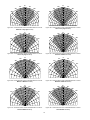
Figure 12E—Horizontal Field of View at Indicated Distance in Feet for
JP-5 at Very High Sensitivity
15°
30°
0°
65 ft
60 ft
30°
45°
0°
100 ft
90 ft
80 ft
70 ft
60 ft
50 ft
40 ft
30 ft
20 ft
10 ft
15°
30°
45°
Figure 12F—Horizontal Field of View at Indicated Distance in Feet for
Gasoline at Medium Sensitivity
15°
15°
30°
30°
50 ft
45°
15°
Figure 12D—Horizontal Field of View at Indicated Distance in Feet for
Diesel at Very High Sensitivity
Figure 12C—Horizontal Field of View at Indicated Distance in Feet for
Methanol at Very High Sensitivity
15°
0°
150 ft
135 ft
120 ft
105 ft
90 ft
75 ft
60 ft
45 ft
30 ft
15 ft
45°
0°
70 ft
15°
30°
60 ft
45°
45°
50 ft
40 ft
40 ft
30 ft
30 ft
20 ft
20 ft
10 ft
10 ft
Figure 12G—Horizontal Field of View at Indicated Distance in Feet for
Methane at Medium Sensitivity
Figure 12H—Horizontal Field of View at Indicated Distance in Feet for
Methanol at Medium Sensitivity
15°
30°
45°
0°
70 ft
60 ft
50 ft
15°
15°
30°
30°
45°
45°
40 ft
30 ft
20 ft
10 ft
Figure 12J—Horizontal Field of View at Indicated Distance in Feet for
Diesel at Medium Sensitivity
0°
100 ft
90 ft
80 ft
70 ft
60 ft
50 ft
40 ft
30 ft
20 ft
10 ft
15°
30°
45°
Figure 12K—Horizontal Field of View at Indicated Distance in Feet for
JP-5 at Medium Sensitivity
16
DEVICE REPAIR AND RETURN
CERTIFICATION—
FM:
Reference Appendix A.
CSA:
Class I, Div. 1, Groups B, C and D;
Class II, Div. 1, Groups E, F and G (T4A);
Class II/III.
Class I, Div. 2, Groups A, B, C and D;
Class II, Div. 2, Groups F and G (T3C);
Class II/III.
Enclosure Type 4X.
Explosion-proof Ambient Temperature Limits:
–55°C to 125°C.
CENELEC: Standard Temperature Model
EEx d IIC T6, EEx d e IIC T6
(Tamb = –40°C to +60°C).
EEx d IIC T5, EEx d e IIC T5
(Tamb = –40°C to +75°C).
IP66.
Extended Temperature Model
EEx d IIC T6, EEx d e IIC T6
(Tamb = –55°C to +60°C).
EEx d IIC T5, EEx d e IIC T5
(Tamb = –55°C to +75°C).
EEx d IIC T4, EEx d e IIC T4
(Tamb = –55°C to +100°C).
IP66.
Integral J-Box Model
EEx d e IIC T6
(Tamb = –40°C to +60°C).
EEx d e IIC T5
(Tamb = –40°C to +70°C).
IP66.
The detector is not designed to be repaired in the field.
If a problem should develop, refer to the
Troubleshooting section. If it is determined that the
problem is caused by an electronic defect, the device
must be returned to the factory for repair.
Prior to returning devices, contact the nearest local
Detector Electronics office so that a Service Order
number can be assigned. A written statement
describing the malfunction must accompany the
returned device or component to expedite finding the
cause of the failure.
Pack the unit properly. Use sufficient packing material
in addition to an antistatic bag or aluminum-backed
cardboard as protection from electrostatic discharge.
Return all equipment transportation prepaid to the
factory in Minneapolis.
NOTE
Since the entire unit must be returned to the
factory for repair, it is highly recommended that a
complete spare be kept on hand for field
replacement to ensure continuous protection.
Special Conditions for Safe Use (“X”):
The extended temperature model can withstand
repeated exposures to +125°C for periods of up to 12
hours while maintaining its explosion-proof rating. It is
recommended that the unit housing be replaced after
500 hours of exposure to the +125°C temperature
condition to maintain explosion-proof rating.
CE:
Conforms to all relevant European norms.
NOTE
Operational performance verified from -40°C to
+75°C.
WARRANTY PERIOD—
5 years, sensor and electronics.
17
95-8517
ORDERING INFORMATION
REPLACEMENT PARTS
When ordering, specify detector sensitivity. Refer to
Appendix A for details.
Part Number
001680-001
ACCESSORIES
006967-001
005003-001
Q9001L Mounting Bracket is recommended for
mounting the detector when using flexible conduit.
For assistance in ordering a system to fit your
application, please contact:
Q9033 Mounting Bracket is for cable gland installation.
Detector Electronics Corporation
6901 West 110th Street
Minneapolis, Minnesota 55438 USA
Operator: (952) 941-5665 or (800) 765-FIRE
Customer Service: (952) 946-6491
Fax: (952) 829-8750
Web site: www.detronics.com
E-mail: [email protected]
Swivel Union is recommended for mounting the
detector to a junction box and allows detector sighting.
18
Description
Window cleaner squeeze bottle
(package of six bottles)
oi plate kit
Silicone-free grease
APPENDIX A
[Factory Mutual Research (FMR) Approval Description]
THE FOLLOWING ITEMS, FUNCTIONS AND OPTIONS DESCRIBE THE FMR APPROVAL:
• Explosion-proof for Class I, Div. 1, Groups B, C and D (T4A) Hazardous (Classified) Locations per FM 3615.
• Dust-ignition proof for Class II/III, Div. 1, Groups E, F and G (T4A) Hazardous (Classified) Locations per FM 3615.
• Non-incendive for Class I, Div. 2, Groups A, B, C and D (T3C) Hazardous (Classified) locations per FM 3611.
• Suitable for Class II/III, Div. 2, Groups F and G (T3C) Hazardous (Classified) locations per FM 3611.
• Enclosure rating NEMA Type 4X per NEMA 250.
• Ambient Temperature Limits:
–40°F to +167°F (–40°C to +75°C).
• Automatic Fire Alarm Signaling Performance verified per FM 3260.
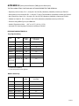
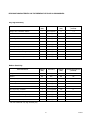
RESPONSE CHARACTERISTICS:
Very High Sensitivity
Fuel
Size
Distance
(feet)
Average Response Time
(seconds)
Gasoline
1 x 1 foot
210*
8.4
Gasoline
1 x 1 foot
100
1.4
Diesel**
1 x 1 foot
150*
9.6
Methanol
1 x 1 foot
150*
5.7
Methane
30 inch plume
100
2.5
JP-5**
2 x 2 foot
210*
8.5
JP-5**
2 x 2 foot
100
2.6
Office
18” x 16” x 10”
Paper 0.5 lb.
100
4.5
Corrugated
Panel
100
14.8
18” x 36”
* Outdoor test condition.
** 10 second pre-burn from ignition.
Medium Sensitivity
Fuel
Size
Distance
(feet)
Average Response Time
(seconds)
Gasoline
1 x 1 foot
100
6.0
Gasoline
1 x 1 foot
50
3.8
Diesel**
1 x 1 foot
70
7.4
Methanol
1 x 1 foot
70
9.7
Methane
30 inch plume
65
2.4
Methane
30 inch plume
55
0.8
2 x 2 foot
100
5.7
JP-5**
** 10 second pre-burn from ignition.
19
95-8517
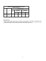
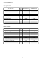
X3300 Pulse Output Response Characteristics
Medium Sensitivity
Ave. Response Time, Sec.
Fuel
Size
Distance
Ft. (M)
Connection to
R7404 Controller
Connection to
R7494 Controller
On Axis (0°) Off Axis (45°) On Axis (0°) Off Axis (45°)
Heptane
36 Sq. In.
(0.023 Sq. M.)
40
(12)
4.5
10.6
5.3
11.4
OPTICAL FAULT:
The detector generated an optical fault in the presence of contamination on any single or combination of lens
surfaces verifying that the detector performs an optical integrity (oi) test for each sensor. Upon removal of the
contaminant the detector fault was cleared and the detector was verified to detect a fire.
20
RESPONSE CHARACTERISTICS IN THE PRESENCE OF FALSE ALARM SOURCES:
Very High Sensitivity
False Alarm Source
Distance
(feet)
Fire Source
Distance
(feet)
Average Response Time
(seconds)
Sunlight, direct, modulated, reflected
—
6-inch propane
6
<4
Vibration
N/A
6-inch propane
6
< 10
Radio frequency interference
1
6-inch propane
12
<1
Arc welding
40
1 x 1 foot gasoline
40
3.1
6 kw heater, modulated
100
1 x 1 foot gasoline
100
1.9
6 kw heater, unmodulated
10
1 x 1 foot gasoline
100
5.3
250 w vapor lamp, modulated
3
1 x 1 foot gasoline
100
2.7
300 w incandescent lamp, modulated
3
1 x 1 foot gasoline
100
3.6
500 w unshielded quartz halogen lamp, modulated
8
1 x 1 foot gasoline
100
2.7
1500 w electric radiant heater, modulated
10
1 x 1 foot gasoline
100
4.2
Two 34 w fluorescent lamps, modulated
3
1 x 1 foot gasoline
100
1.7
Distance
(feet)
Fire Source
Distance
(feet)
Average Response Time
(seconds)
Sunlight, direct, modulated, reflected
—
6-inch propane
6
<4
Vibration*
N/A
N/A
N/A
N/A
Radio frequency interference
1
6-inch propane
6
<1
Arc welding
10
1 x 1 foot gasoline
10
0.2
6 kw heater, modulated
100
1 x 1 foot gasoline
100
5.0
6 kw heater, unmodulated
10
1 x 1 foot gasoline
100
10.7
250 w vapor lamp, modulated
3
1 x 1 foot gasoline
100
7.1
300 w incandescent lamp, modulated
3
1 x 1 foot gasoline
100
9.6
500 w unshielded quartz halogen lamp, modulated
8
1 x 1 foot gasoline
100
6.3
1500 w electric radiant heater, modulated
10
1 x 1 foot gasoline
90
6.4
Two 34 w fluorescent lamps, modulated
3
1 x 1 foot gasoline
100
4.6
Medium Sensitivity
False Alarm Source
* Fire was verified with very high sensitivity only.
21
95-8517
FALSE ALARM IMMUNITY:
Very High Sensitivity
False Alarm Source
Distance
(feet)
Modulated Response
Unmodulated Response
—
No alarm
No alarm
N/A
No alarm
N/A
Radio frequency interference
1
No alarm (keyed)
No alarm (steady)
Arc welding
40
No alarm
No alarm
6 kw heater
3
No alarm
No alarm
250 w vapor lamp
3
No alarm
No alarm
300 w incandescent lamp
3
No alarm
No alarm
500 w unshielded quartz halogen lamp
8
No alarm
No alarm
1500 w electric radiant heater
3
No alarm
No alarm
Two 34 w fluorescent lamps
3
No alarm
No alarm
Distance
(feet)
Modulated Response
Unmodulated Response
—
No alarm
No alarm
N/A
No alarm
N/A
Radio frequency interference
1
No alarm (keyed)
No alarm (steady)
Arc welding
10
No alarm
No alarm
6 kw heater
3
No alarm
No alarm
250 w vapor lamp
3
No alarm
No alarm
300 w incandescent lamp
3
No alarm
No alarm
500 w unshielded quartz halogen lamp
8
No alarm
No alarm
1500 w electric radiant heater
3
No alarm
No alarm
Two 34 w fluorescent lamps
3
No alarm
No alarm
Sunlight, direct, reflected
Vibration
Medium Sensitivity
False Alarm Source
Sunlight, direct, reflected
Vibration
22
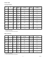
FIELD OF VIEW:
Very High Sensitivity
Fuel
Size
Distance
(feet)
Horizontal
(degrees)
Avg. Horiz. Response Time
(seconds)
Vertical
(degrees)
Avg. Vert. Response Time
(seconds)
Gasoline
1 x 1 foot
150
+45
–45
11.9
9.5
+45
–30
8.5
6.0
Gasoline
1 x 1 foot
100
+45
–45
3.5
4.0
+45
–30
4.2
3.2
Diesel**
1 x 1 foot
100
+45
–45
2.2
4.4
+45
–30
2.1
2.8
Methanol
1 x 1 foot
110
+45
–45
8.5
9.2
+45
–30
9.5
4.3
Methane
30 inch plume
100
+45
–45
1.9
4.3
+45
–30
3.5
2.0
JP-5**
2 x 2 feet
180*
+45
–45
13.3
17.3
+45
–30
10.4
5.0
JP-5**
2 x 2 feet
90
+45
–45
2.9
4.1
+45
–30
1.4
2.5
Office
18” x 16” x 10”
Paper 0.5 lb.
80
+45
–45
6.4
9.8
+45
–30
8.2
6.0
Corrugated
Panel
80
+45
–45
15.6
12.2
+45
–30
14.7
10.6
18” x 36”
* Outdoor test condition.
** 10 second flame pre-burn from ignition.
Medium Sensitivity
Fuel
Size
Distance
(feet)
Horizontal
(degrees)
Avg. Horiz. Response Time
(seconds)
Vertical
(degrees)
Avg. Vert. Response Time
(seconds)
Gasoline
1 x 1 foot
75
+45
–45
9.5
9.5
+45
–30
6.4
5.4
Gasoline
1 x 1 foot
50
+45
–45
3.8
3.8
+45
–30
4.1
3.1
Diesel**
1 x 1 foot
60
+45
–45
4.5
6.8
+45
–30
5.5
2.1
Methanol
1 x 1 foot
45
+45
–45
9.0
9.7
+45
–30
9.8
6.6
Methane
30 inch plume
45
+45
–45
4.4
0.9
+45
–30
2.0
0.5
Methane
30 inch plume
40
+45
–45
1.7
0.4
+45
–30
3.4
1.4
2 x 2 feet
90
+45
–45
2.9
8.1
+45
–30
3.4
2.5
JP-5**
* Outdoor test condition.
** 10 second flame pre-burn from ignition.
23
95-8517
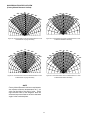
HIGH RESOLUTION FIELD OF VIEW
(Factory Mutual Research Verified)
20°
10°
30°
40°
45°
0°
100
90
80
10°
20°
20°
30°
30°
40°
45°
70
60
50
40
30
20
10
40°
45°
30°
40°
45°
10°
0°
150
135
120
105
90
75
60
45
30
15
10°
20°
30°
40°
45°
50
40
30
20
10
Figure A1—Horizontal Field of View at Indicated Distance in Feet
for Methane at Very High Sensitivity
20°
0°
10° 65
60
10°
Figure A2—Horizontal Field of View at Indicated Distance in Feet
for Methane at Medium Sensitivity
20°
20°
30°
30°
40°
40°
45°
45°
0°
10° 70
60
50
10°
20°
30°
40°
45°
40
30
20
10
Figure A3—Horizontal Field of View at Indicated Distance in Feet
for Methanol at Very High Sensitivity
Figure A4—Horizontal Field of View at Indicated Distance in Feet
for Methanol at Medium Sensitivity
NOTE
Factory Mutual Research minimum requirements
are response distance measurements at 0° (on
axis) and the limits of the field of view. These
high resolution field of view diagrams show the
measured response distances at all the indicated
angles in the horizontal plane.
24
Printed in USA
Detector Electronics Corporation
6901 West 110th Street • Minneapolis, Minnesota 55438 USA
Tel: 952.941.5665 or 800.765.3473 • Fax: 952.829.8750