1
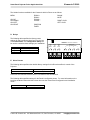
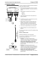
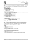
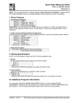
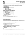
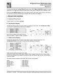
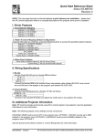
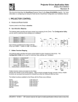
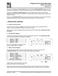
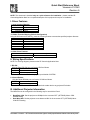
Quick Start Reference Sheet
Viewsonic PJ1060
Revision A
NOTE: This document is intended only as a quick reference for installation – please read the SP
Controls Application Note for a complete description of this projector driver prior to installation.
I. Driver Features
1. Input Selection Mapping
Selection 1:
Selection 2:
Selection 3:
Selection 4:
VIDEO
VIDEO
RGB 1
RGB 2
2. Hidden Function Mapping (Default Configuration)
Using the ON button as a shift key, press the following buttons to access the specified projector features.
Selection 1:
Selection 2:
Selection 3:
Selection 4:
Off:
Volume Up:
Volume Down:
BLANK
MUTE
ADJ LEFT
ADJ RIGHT
MENU
ADJ UP
ADJ DOWN
3. Other Driver Features
Power Status Feedback Method
Control Wiring
RS-232 Power Polling
RS-232 and Infrared Emitter
II. Wiring Specifications
NOTE: For a wiring diagram, please see the SP Controls Application Note.
1. RS-232:
Wire the Panel RS-232 port to a female HD15 as follows:
TX to 13
RX to 14
GND to 10
Connect this female HD15 to the projector port labeled CONTROL.
2. Infrared Emitter:
Wire the Panel IR/Serial port to a female 1/8" Mini as follows:
IR/SER to tip
GND to ring
Connect to the included IR Emitter and attach the emitter bud to any projector IR window.
III. Additional Projector Information
The MP8670 must be configured in the following way for use with the Panel:
•
•
Baud Rate 9600: Set the projector to 9600bps in the onscreen OPT. (OPTIONS) Menu: COM.
SPEED setting.
Data Word 8N1: Set the projector to use data word 8N1 in the onscreen OPT. (OPTIONS) Menu:
COM. BITS setting.
DR-VWS03 - 12/18/03
SP Controls reserves the right to modify specifications without notice at any time.
Projector Driver Application Note
Viewsonic PJ1060
Revision A
This document describes the Smart Panel Projector Driver for the Viewsonic PJ1060 projector. For
more information on configuring and using the Panel see the Smart Panel Configuration and Installation
Guide.
Please read the SPECIAL CONTROL NOTE below before attempting to control the Viewsonic. This
driver is known to work only when the projector is configured for serial communication at 9600 8N1.
I. PROJECTOR CONTROL
A. Volume and Power Control
Volume control for the Viewsonic is absolute.
Absolute volume control for this model is also possible with use of SP Controls’ optional Audio Follow
Video Pre-Amplifier.
B. Input Selection Mapping
The following table specifies the factory preset input mapping for this Driver. The Configuration Utility
can be used to customize these settings your installation.
Selection 1:
Selection 2:
Selection 3:
Selection 4:
VIDEO
VIDEO
RGB 1
RGB 2
RGB 1
RGB 2
VIDEO 2
Projector
VIDEO 1
Volume
ON
Ready
OFF
Warm-up
Input choices available with this Driver are
VIDEO, RGB 1 and RGB 2.
C. Hidden Function Mapping
The following table specifies the factory preset hidden function mapping for this Driver. The
Configuration Utility can be used to customize these settings your installation.
Selection 1:
Selection 2:
Selection 3:
Selection 4:
Off:
Volume Up:
Volume Down:
BLANK
MUTE
ADJ LEFT
ADJ RIGHT
MENU
ADJ UP
ADJ DOWN
ADJ LEFT
ADJ UP
ADJ RIGHT
MUTE
Projector
Volume
ON
BLANK
Ready
OFF
Warm-up
MENU
ADJ DOWN
Hidden functions names are based on the Viewsonic remote control and projector-top controls.
Menu both summons and dismisses on screen menus. Adjust controls navigate through onscreen
menus. Blank and Mute are toggles. Note that on-screen menus can not be summoned if no source
is detected on the currently selected input! (This is a Viewsonic behavior not under Panel
control).
Hidden functions are accessed by pressing the indicated key while the holding the On key down.
DR-VWS03 - 12/18/03
SP Controls reserves the right to modify specifications without notice at any time.
Smart Panel Projector Driver Application Note
Viewsonic PJ1060
The hidden functions available for the Viewsonic with this Driver are as follows:
MENU
ZOOM +
ZOOM –
FOCUS +
FOCUS –
ADJ UP
ADJ DOWN
ADJ LEFT
ADJ RIGHT
BLANK
MUTE
RIGHT CLICK
LEFT CLICK
POSITION
TIMER
D. Relays
500mA MAX. CURRENT
1
7B
7A
6B
6A
5B
5A
SELECTION
(EXT. SWITCHER CTRL)
3
2
4B
4
4A
3A
3B
PWR
OFF
MOM.
2B
PWR
ON
MOM.
2A
ON Maintained
ON Momentary
OFF Momentary
Momentary; not Binary
PWR
ON
MAINT.
1B
Relay 1
Relay 2
Relay 3
Selection
RELAYS
1A
The following table specifies the factory preset
settings for the low-current relays found on the rear
of the Smart Panel. The Configuration Utility can
be used to customize these settings your installation.
E. Other Presets
The following table specifies other default factory settings for this Driver that affect is control of the
Projector.
Power Status Feedback Method
Control Wiring
RS-232 Polling (see note 1)
Infrared Emitter (see note 2)
Control for the Viewsonic with this Driver is via both RS-232 and Infrared.
The following table specifies settings for the Panel’s configurable timers. For more information on the
inactivity shutdown feature and the lockout timer see the Smart Panel Configuration and Installation
Guide.
Lockout Timer
Inactivity Shutdown
80 seconds (see note 3)
Disabled
© 2003 SP Controls Inc. 601 Minnesota Suite 115, San Francisco, CA 94107
[email protected]
Smart Panel Projector Driver Application Note
Viewsonic PJ1060
II. CONTROL WIRING
This section specifies how RS-232 and Infrared should be
wired to the Viewsonic projector.
PROJECTOR CONTROL
Female HD15
TX to pin 13
RX to pin 14
GND to pin 10
A. RS-232 should be connected to the D-sub 15 female
terminal labeled CONTROL. Connection should be as
follows:
1 2 3 4 5
6 7 8 9 10
11 12 13 14 15
GND
SENSE
IR/SER
+12V
GND
IR/SERIAL
CTS
RTS
TX
RX
RS232
1/8" Mini
Female
1.
Wire the Panel to a female D-sub 15 as follows:
TX to 13
RX to 14
GND to 10
2.
Connect this female connector to the projector port
labeled CONTROL.
B. The IR Emitter should be connected to the one of the
Viewsonic IR windows as follows:
1. Wire the Panel to a female 1/8” Mini as show; wire
IR/SER to tip and GND to ring. Splicing and direct
wiring to the IR Emitter is not recommended as it
makes removal of the Panel for service more difficult.
2. Connect the included IR Emitter to the female mini.
IR Emitter
(included with Panel)
3. Affix the IR Emitter to one of the IR windows on the
projector.
RS-232 to
CONTROL
IR Emitter to
any IR window
Note that the emitter glows red when IR is emitted so wiring
can be verified.
SPECIAL CONTROL NOTE
Read before attempting to control the projector
The Viewsonic is configurable in ways that impact the
possibility of Smart Panel control:
•
Baud Rate: The Viewsonic projector may be
configured via the onscreen menus to accept RS-232
control over a range of speeds. This Driver assumes
control will take place at 9600bps. Insure that the
projector is set to 9600bps in the onscreen OPT.
(OPTIONS) Menu: COM. SPEED setting. If not, set the
projector to 9600.
•
Data Word: The Viewsonic projector may be
configured via the onscreen menus to accept RS-232
control over a range of data word settings. This Driver
assumes control will take place with 8 data bits, no
parity bit, and one stop bit (8N1). Insure that the
projector is set to 8N1 in the onscreen OPT.
(OPTIONS) Menu: COM. BITS setting. If not, set the
projector to 8N1.
© 2003 SP Controls Inc. 601 Minnesota Suite 115, San Francisco, CA 94107
[email protected]
Smart Panel Projector Driver Application Note
Viewsonic PJ1060
III. TROUBLESHOOTING
Additional tips can be found in the Smart Panel Configuration and Installation Guide.
The Panel does not do anything at all.
When power is applied to the Panel it should run through a brief power on self-test, during which all of
the Panel lights will turn on and off in sequence. If you do not see this self test, make sure power is
connected correctly and that polarity is correct.
The Panel keeps turning itself off even though the projector is on.
The Panel turns itself off when power verification indicates that the projector is off. Check to make
sure the RS-232 connection is correctly wired. If a third party power current sensor is being used,
make sure correctly wired and calibrated. The most common cause for power polling failure when
other control works, is that the RX line is incorrectly wired or soldered. Also, see the next issue
The Panel comes on, but cannot control the projector (and soon turns itself off!).
Make sure the Viewsonic is correctly configured for serial communications at 9600 8N1. If the
projector is set to any other control rate and data format, control will fail regardless of whether wiring
is correct. For information on how to verify and set the projector’s serial communications settings, see
the SPECIAL CONTROL NOTE in the control wiring section of this document.
The projector keeps turning itself off, though the Panel is on (then the Panel then shuts itself off).
The Viewsonic may be configured to shut itself off in the absence of any valid input signal. Refer to
the Viewsonic manual for instructions on how to set and disable this behavior with onscreen menus.
Alternately, ensure that Panel is not configured with an unexpected value for Inactivity Shutdown.
The onscreen menus won’t appear!.
Note that the Viewsonic will not display on screen menus if there is not a valid source signal on the
currently selected input. This is a Viewsonic behavior that the Panel cannot control. During testing it
was also noticed that occasionally when the Panel reset after download, onscreen menus would not
appear. Hard power cycling the projector seemed to remedy this behavior.
When I try to turn the projector on, the warming indicator (red LED) blink.
The projector is in lockout mode, and the Panel is waiting for its internal lockout timer to expire; this
feature protects the projector’s bulb. Be sure to let your client know about this behavior.
IV. TECHNICAL NOTES
1.
By default, projector power is verified by polling every few seconds via the RS-232 port. Power
polling can be suspended by depressing and holding the On key; polling will be restored when the
key is released. Should the Viewsonic power off, the Panel will usually detect this condition and
power off within thirty seconds. Should the Viewsonic power on, the Panel will usually detecting this
condition and power on within fifteen seconds.
2.
This Viewsonic is currently controlled via a combination of Infrared and RS-232 only. Wired Remote
is not an option as the Viewsonic does not have a Wired Remote port.
3.
The lockout timer specifies the amount of time allowed between sending POWER OFF and POWER
ON to the projector (the delay allows the projector bulb to cool before re-powering). This delay can
be configured using the Configuration Utility; however, adjusting the lockout timer delay is
strongly discouraged as rapid re-powering causes undue wear on the projector’s bulb. Also, the
Viewsonic will not allow power to be restored before a minimum delay has expired. Therefore,
disabling the lockout delay will cause potentially confusing Panel behavior.
© 2003 SP Controls Inc. 601 Minnesota Suite 115, San Francisco, CA 94107
[email protected]
Smart Panel Projector Driver Application Note
Viewsonic PJ1060
V. REVISION HISTORY
1.
Revision A (December,2003) Initial Release
© 2003 SP Controls Inc. 601 Minnesota Suite 115, San Francisco, CA 94107
[email protected]