1
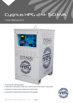
Cygnus Portable Solar Generator User Manual v3.0 2011 For use with the following models: CYG2400/460/24, CYG2400/920/24, CYG2400/1380/24, CYG3500/920/24, CYG3500/1380/24, CYG5000/920/24, CYG5000/1380/24 Cygnus User Manual - v3.0 2011 Page 1 Table of Contents 1. Introduc on .............................................................................................................................................. 4 1.1 Foreword ............................................................................................................................................. 4 1.2 Conven ons......................................................................................................................................... 4 1.2.1 Terminology .................................................................................................................................. 4 1.2.2 Warnings ....................................................................................................................................... 4 1.3 Standards & Regula ons ...................................................................................................................... 5 1.4 Disposal & Recycling ............................................................................................................................ 5 1.5 Firefly Solar Contact Details ................................................................................................................. 5 1.6 About Firefly Solar ............................................................................................................................... 5 2. Ge ng Started ......................................................................................................................................... 6 2.1 Storage ................................................................................................................................................ 6 2.2 Transporta on, Loading/Unloading & Posi oning................................................................................ 6 2.2.1 Transporta on .............................................................................................................................. 6 2.2.2 Loading/Unloading ........................................................................................................................ 6 2.2.3 Posi oning .................................................................................................................................... 6 2.3 Understanding the Cygnus Control Panel ............................................................................................. 7 2.3.1 Diagram of the Cygnus Control Panel ............................................................................................ 7 2.3.2 Explana on of the Cygnus Control Panel ....................................................................................... 7 2.4 Connec ng the Cygnus Portable Solar Generator ................................................................................ 8 2.4.1 Earth A achment: Installing the Op onal Earth Rod ..................................................................... 8 2.4.2 Connect the Inputs ........................................................................................................................ 8 2.4.3 Connect the Output Power Cables................................................................................................. 9 3. General Opera on .................................................................................................................................. 10 3.1 Turning the Power On ........................................................................................................................ 10 3.2 Monitoring the Power ....................................................................................................................... 11 3.2.1 Displaying Real- me Ba ery Bank Voltage .................................................................................. 11 3.2.2 Displaying the Ba ery Bank SOC.................................................................................................. 11 3.3 Emergency Stop Bu on ..................................................................................................................... 12 3.4 Turning Off Cygnus ............................................................................................................................ 12 3.5 Disconnec ng Cygnus ........................................................................................................................ 12 3.6 Understanding the RCC-03 ................................................................................................................. 13 3.6.1 Explana on of the Informa on Shown on the RCC-03 ................................................................. 13 3.7 Charging Methods ............................................................................................................................. 14 3.7.1 Charging with Firefly’s Portable Folding Solar Array (Fold-Array) ................................................. 14 3.7.1.1 Connec ng ............................................................................................................................ 14 3.7.1.2 Disconnec ng ....................................................................................................................... 14 3.7.2 Charging with Kinectrics Equipment ............................................................................................ 15 3.7.2.1 Connec ng ............................................................................................................................ 15 3.7.2.2 Disconnec ng ....................................................................................................................... 15 3.7.3 Charging with AC Grid Supply or Secondary Power System .......................................................... 15 4. Connec ng Mul ple Cygnus Portable Solar Generators ......................................................................... 16 4.1 Introduc on ................................................................................................................................... 16 4.2 Connec ng in Parallel ..................................................................................................................... 16 4.3 Connec ng in Series ....................................................................................................................... 17 4.4 Turning Off the Units ...................................................................................................................... 18 4.5 Disconnec ng Data Interlink Cables ............................................................................................... 18 Cygnus User Manual - v3.0 2011 Page 2 Table of Contents (Con nued) 5. Care and Maintenance ............................................................................................................................ 19 5.1 General Cleaning ............................................................................................................................... 19 5.2 Washing Cygnus with a High Pressure Cleaner or Hosepipe ............................................................... 19 5.3 Paintwork Repair ............................................................................................................................... 19 5.4 Tes ng ............................................................................................................................................... 19 5.5 Caring for the Ba ery Bank ................................................................................................................ 19 6. Appendices ............................................................................................................................................. 20 6.1 Appendix 1 - Addi onal RCC-03 Se ngs ............................................................................................ 20 6.1.1 Boos ng the Voltage Over Distance ............................................................................................ 20 6.1.2 Se ng the RCC-03 Language ....................................................................................................... 20 6.2 Appendix 2 - 24V DC SPEC Pak Input/Output ..................................................................................... 21 6.2.1 Connec ng ................................................................................................................................. 21 6.2.2 Disconnec ng .............................................................................................................................. 21 6.3 Appendix 3 - Example Configura ons................................................................................................. 22 6.3.1 On or Off Grid UPS....................................................................................................................... 22 6.3.2 Single Cygnus Portable Solar Generator ...................................................................................... 23 6.3.3 Three Phase Cygnus System ........................................................................................................ 24 6.3.4 Two Unit Parallel Cygnus System ................................................................................................. 25 6.3.5 Kinectrics PedGen Connected to Single Cygnus ........................................................................... 26 6.4 Appendix 4 - Troubleshoo ng Guide .................................................................................................. 27 6.5 Appendix 5 - Technical Data ............................................................................................................... 28 6.6 Appendix 6 - Further Reading ............................................................................................................ 29 Figures Fig. 1 - Cygnus Control Panel Component Reference ................................................................................... 7 Fig. 2 - RCC03, Unit in Standby ..................................................................................................................10 Fig. 3 - RCC03, Unit On ..............................................................................................................................10 Fig. 4 - The RCC 03 ....................................................................................................................................13 Fig. 5 - 24V 80 A DC SPEC Pak Connector ...................................................................................................21 Fig. 6 - Example Showing a Single Unit Connected to an AC Feed and Powering Consumers .....................22 Fig. 7 - Example Showing Arrays Directly Connected to the Unit’s Solar Inputs .........................................23 Fig. 8 - Example Showing the use of a Junc on Box to Allow the use of More Than Two Arrays ................23 Fig. 9 - Example Showing the use of Three Units to Provide a Three Phase Output ...................................24 Fig. 10 - Example Showing the use of Two Units to Provide a Higher Output .............................................25 Fig. 11 - Example Showing the use of Two Kinectrics units to Charge Cygnus ............................................26 Fig. 12 - Example Showing the use of Eight Kinectrics Units to Charge Cygnus ..........................................26 Fig. 13 - Technical Data .............................................................................................................................28 Cygnus User Manual - v3.0 2011 Page 3 1. Introduc on 1.1 Foreword Firefly Solar Generators Limited takes this opportunity to congratulate you on the purchase of your new Cygnus Porta-‐ ble Solar Generator. Designed and manufactured within the United Kingdom using only the finest European sourced electrical components, your new Cygnus Portable Solar Generator offers sustainable power genera on with the reliability that you demand. The purpose of this manual is to introduce you to the Cygnus Portable Solar Generator and provide you with a guide to the processes of se ng up and opera ng your new product. This manual describes how your Cygnus Portable Solar Generator works, will help you with fault finding and examines what each component is doing and why. 1.2 Conven ons Throughout this user manual the following symbols are used: W A R N I N G This symbol warns of the presence of a dangerous voltage which could cause harm to the operator. This symbol indicates the poten al of damage to the unit or connected devices. This symbol indicates important or useful informa on. 1.2.1 Terminology The following terms are used in this manual to provide greater clarity: Firefly Solar Generators Ltd. will be referred to as “The manufacturer”. The Cygnus Portable Solar Generator will be referred to as ‘Cygnus’ or ‘Unit’. Any items that consume power will be referred to as ‘Consumers’. State of Charge of the ba ery bank will be referred to as ‘SOC’. 1.2.2 Warnings This user manual is an important part of the Cygnus Portable Solar Generator. It must be kept available to all operators and kept close to the unit so that it can be referred to at any me. W A R N I N G When the unit is opera ng it generates poten ally lethal voltages. Work must only be performed on the unit by the manufacturer or a qualified service engineer approved by the manufacturer. Under no circumstances should operators open the unit’s enclosure. All items connected to the unit including distribu on cables and boxes should be regularly checked and adhere to the same local regula ons and standards as a regular grid- ed mains installa on. Cygnus User Manual - v3.0 2011 Page 4 1.3 Standards & Regula ons The Cygnus Portable Solar Generator conforms to the following standards and regula ons: Manufactured in compliance with ISO 9001:2008 LVD 73/23/EEC EN 61000-6-1, EN 61000-6-3, EN 55014 IP23 WEEE Direc ve 1.4 Disposal & Recycling The Cygnus Portable Solar Generator comprises of components that must disposed of responsibly. For the sake of the environment many of the components within the unit can be recycled or reused. Firefly Solar Generators Ltd. will en-‐ sure the safe decommissioning and recycling of the unit at no charge if the unit is returned to the manufacturer. Other-‐ wise, please contact the manufacturer for more informa on on safe and proper decommissioning of your Cygnus Porta-‐ ble Solar Generator. 1.5 Firefly Solar Contact Details Firefly Solar Generators Ltd The Green Warehouse Court Farm House King George VI Avenue Hove East Sussex BN3 6XJ United Kingdom 1.6 Tel: +44 (0) 1273 617 006 Fax: +44 (0) 1273 316 646 E-mail: info@fireflysolar.net Web: www.fireflysolar.net About Firefly Solar Firefly Solar is the European market leader in the design and manufacturer of off-grid, portable and permanent solarpowered generators. Our green energy products and services meet the needs of environmentally concerned individuals and organisa ons who are looking to reduce the carbon emissions caused by the use of fossil fuels and diesel powered equipment. Firefly Solar generators harness energy supplied by the sun using photovoltaic (PV) cells, storing it for when it’s needed. Addi onally, mul -charge inputs allows kine c and wind energy to be stored for convenient use. We are specialists in green energy storage systems – our exper se in ba eries, electronics and so ware has enabled our generators to over-‐ come many of the problems of intermi ency which can be associated with renewable energy sources. Firefly Solar generators can provide an uninterrupted electrical supply even in the absence of light or other charging input. Our award-winning products, which include the Orion, Cygnus, Pictor & Pyxis models, have been widely used by well-known brands such as Coca-Cola Enterprises, the BBC, Sky, Greenpeace, Friends of the Earth and Solar Aid. Firefly Solar provide temporary stand-alone power for the events, broadcast, and construc on industries; permanent stand-alone power for rural loca ons and telecommunica ons; and back-up (UPS) power with extended run mes for loca ons with intermi ent grid connec vity. Firefly Solar power genera ng equipment is zero emission, true silent run-‐ ning and eliminates the need for inflammable fuel. Cygnus User Manual - v3.0 2011 Page 5 2. Ge ng Started 2.1 2.2 Storage 1. Cygnus is designed to be used and stored outside. However, to prevent unnecessary weathering it is recom-‐ mended that the unit is stored inside when possible. 2. It is recommended that the ba ery bank is charged regularly while in storage. Refer to Chapter 4, Sec on 5 for further informa on. 3. Cygnus should be switched off when in storage and not being charged to prevent unnecessary discharge of the ba ery bank. Transporta on, Loading/Unloading & Posi oning 2.2.1 Transporta on 1. 2. 3. Cygnus can be transported using a suitable trailer, light or heavy goods vehicle with adequate available payload. Check the relevant transporta on documenta on for suitability. The gross weight of the unit can be found on the ra ng plate posi oned on the le hand side of the unit. Please note that different models have different weights. It is recommended that the unit is secured using suitable straps when in transit to prevent it from moving. Always check the ra ng plate to ascertain the gross weight of the specific unit in ques on. The unit must remain upright at all mes. 2.2.2 Loading/Unloading 1. Cygnus must be loaded or unloaded using the correct equipment operated by suitably trained personnel. 2. Using the li ing ring; Cygnus can be li ed onto or off from transporta on. The li ing ring is suitable for li ing all models of Cygnus regardless of the unit’s gross weight. 3. Using the fork pockets; Cygnus can be loaded or unloaded with a suitable fork-li truck. Refer to the fork-li truck opera on manual for li ing capacity and manufacturer’s opera ng instruc-‐ ons. 2.2.3 Posi oning 1. The unit must be posi oned upright on a flat, solid surface. Ensure that the unit is not at risk from being sub-‐ mersed in water above the fork pockets. 2. The unit should be posi oned as close as possible to the chosen charging system (e.g. solar array, Kinectrics equipment, wind turbine) and close to its earth point. Cygnus User Manual - v3.0 2011 Page 6 2.3 Understanding the Cygnus Control Panel 2.3.1 Diagram of the Cygnus Control Panel Fig. 1 - Cygnus Control Panel Component Reference 2.3.2 Explana on of the Cygnus Control Panel A1 Solar Array 1 Isolator Switch– Switch off to isolate the Solar Array 1 circuit, on to enable it A2 Solar Array 2 Isolator Switch– Switch off to isolate the Solar Array 2 circuit, on to enable it A3 Solar Array 1 Inputs– 24V MC3 inputs for Solar Array 1 A4 Solar Array 2 Inputs– 24V MC3 inputs for Solar Array 2 B1 240V AC Out RCD– Earth leakage protec on for main AC output (Residual Current Device) B2 240V AC Out MCB– Overload protec on for main AC output (Miniature Circuit Breaker) C1 Smartgauge Ba ery Monitor– Provides a real- me display of ba ery bank voltage or SOC C2 RCC-03– Displays real- me informa on on inputs and outputs, also allows their adjustment C3 Open / Terminate Switch– Used when mul ple Cygnus Portable Solar Generators are linked together C4 Power On / Off Switch– Enable or disable AC output C5 Earth Connec on– For earth rod (ground) connec on C6 Emergency Stop Bu on– Disconnects all circuits in an emergency D1 Data 1 Connector– For connec ng data cable in from another Cygnus when mul ple units are used D2 Data 2 Connector– For connec ng data cable out to another Cygnus when mul ple units are used D3 Data 3 Connector– For use with op onal charge controller remote control and display E1 240V AC Input– For charging the unit from the na onal grid or secondary power system E2 240V AC Output– Main output for powering consumers F1 24V DC SPEC Pak Input / Output– For charging from wind or Kinectrics devices. Also gives 2 x 24V DC 40 A output Cygnus User Manual - v3.0 2011 Page 7 2.4 Connec ng the Cygnus Portable Solar Generator 2.4.1 Earth a achment: Installing the Op onal Earth Rod: 1. Find a suitable place to drive the earth rod into the ground. The earth rod should be driven down at least 600mm into the ground using a mallet and placed as near to the unit as possible. 2. Check the earth cable is securely clamped to the rod. The clamp may need re ghtening a er driving the earth rod down. 3. On the control panel, locate the earth bolt (Fig. 1, C5) undo the earth bolt wing nut and remove one of the washers. Then slide the ring terminal at the end of the earth cable onto the earth bolt. Replace the washer and ghten the wing nut. W A R N I N G A protec ve earth must be connected to the unit in compliance with applicable local standards and regula ons. This can be done either by connec ng to a suitable exis ng electrical earth, or by using an op onal earth rod supplied by the manufacturer. 2.4.2 Connect the Inputs: There are a number of means available to charge the unit. Instruc ons on how to connect charging inputs (e.g. solar PV, wind turbines, Kinectrics equipment) are available as appendices to this manual or included with those products at the point of purchase. All user manuals can also be downloaded from the manufacturer’s website at www.fireflysolar.net It is also possible to operate the unit only using the internal ba ery bank, without external inputs connected. W A R N I N G Care must be taken to ensure that the correct connec ons are made to avoid the risk of electrocu on or possible damage to the unit’s internal components. W A R N I N G Ensure that the cumula ve power of connected consumers does not exceed the maximum power out-‐ put of your unit– refer to the ra ng plate to ascertain the unit’s maximum power output. W A R N I N G All connected consumers must be fit for purpose– refer to their ra ng plates and manuals to ascertain the required input. When Cygnus is connected to an external AC supply, the output voltage is transferred from its input. In this case the unit will not modify the AC output: Consumers will be supplied with an output iden cal to the source. Cygnus User Manual - v3.0 2011 Page 8 2.4.3 Connect the Output Power Cables: Cygnus is supplied with a 16A industrial CEEform socket for the connec on of AC power out to consumers requiring (Fig. 1, E2). 1. Before any power connec ons are made, ensure that both the RCD (Fig. 1, B1) and MCB (Fig. 1, B2) are switched Off. 2. Plug in the electrical consumers to the AC Out (Fig. 1, E2) socket on the control panel using a 16A CEEform industrial plug. Cygnus User Manual - v3.0 2011 Page 9 3. General Opera on 3.1 Turning the Power On Once all the above connec ons are complete, the unit is ready to be switched on. 1. Ensure that the Emergency Stop bu on is not depressed by rota ng clockwise (Fig. 1, C6) 2. Switch on the RCD and MCB switches (Fig. 1, B1 & B2). 3. Switch on the unit using the Power On/Off Switch (Fig. 1, C4). 4. As the unit is switched on, a loud beep will be heard and the RCC-03 (Fig. 1, C2) backlight will illuminate. 5. The unit is now in standby mode. 6. “Message 012 use of ba ery temperature sensor” will be displayed for five seconds. 7. A er which, the following should be displayed: Fig. 2 - RCC-03, Unit in Standby 8. Press ESC on the RCC-03. The message ‘Turn the System On?’ will be displayed. 9. Press SET to accept and the unit will go out of standby mode and turn on. A number of changes will appear on the RCC-03. 10. The following will be displayed on the RCC-03: Fig. 3 - RCC-03, Unit On 11. The unit is now on and ready to supply power to connected consumers. Cygnus User Manual - v3.0 2011 Page 10 3.2 Monitoring the Power Cygnus’ control panel includes a ba ery monitoring system which displays the state of charge and voltage of its ba ery bank. Monitoring the state of charge (SOC) of the ba ery bank allows the user to ascertain the remaining ba ery capacity. 3.2.1 Displaying Real- me Ba ery Bank Voltage The real- me voltage of the ba ery bank is displayed by pressing the VOLT bu on on the Smartgauge (Fig. 1, C1). 3.2.2 Displaying Ba ery Bank SOC The SOC is displayed by pressing the Status bu on on the Smartgauge (Fig. 1, C1) ba ery monitor. It is indicated by a number preceded with the le er ‘C’ (e.g. C75). This indicates the percentage of ba ery life le in the unit. E.g. C75 indicates that there is 75% ba ery capacity remaining. The Smartgauge will only indicate the ba ery level down to C30. This is because the ba eries should not be discharged below 30% of their capacity to ensure that they are never allowed to discharge completely, as this will shorten their life me considerably. The opera ng range is from C100 to C30. Once the Smartgauge reaches C30 Cygnus will automa cally switch into Standby Mode and stop delivering AC power un l it is sufficiently recharged. If the 30% lower limit is reached the Smartgauge’s internal alarm will be triggered and its display will flash between C29 and error code ‘A LS’. The red LED indicator marked ‘ALARM’ on the Smartgauge will also illuminate. To restart the unit, the ba ery bank must be charged back up to above 30%. The Smartgauge's BATT2 bu on is not used and should be ignored. Cygnus User Manual - v3.0 2011 Page 11 3.3 3.4 Emergency Stop Bu on 1. If there is an emergency and it is necessary to stop the power from the unit, depress the Emergency Stop Bu on (Fig. 1, C6) on the Control Panel. 2. The unit will then shut down. Cygnus can not be switched on again un l the Emergency Stop Bu on is released by twis ng the red part of the bu on clockwise. 3. Follow the instruc ons in Sec on 4 to switch the power back on. Turning Off Cygnus 1. To turn the unit off press ESC on the RCC-03 (Fig. 1, C2). ’Turn the System Off?’ will be displayed. 2. Press SET to accept. The unit will then go into standby mode. 3. To fully shut down the unit press the On/Off Bu on (Fig. 1, C4) on the control panel. 4. Turn off the RCD and MCB switches (Fig. 1, B1 & B2). 5. The RCC-03 (Fig. 1, C2) screen will then turn off. 6. Switch off all solar isolator switches (Fig. 1, A1 & A2) The Smartgauge ba ery monitor display will always remain on. 3.5 Disconnec ng Cygnus 1. Ensure that the steps in Sec on 4 “Turning Off Cygnus” have been followed. 2. Disconnect the input cable(s). 3. Disconnect the output cable(s) 4. Remove the earth cable by unscrewing the wing nut and replace the washer and wing nut onto the earth bolt. Cygnus User Manual - v3.0 2011 Page 12 3.6 Understanding the RCC-03 The RCC-03 gives a real- me indica on of the power draw of your consumers, the AC charge facility, DC volts and Amps being discharged and the present state of the system as a whole. The following diagram indicates the informa on available from the RCC-03: Fig. 4 - The RCC-03 3.6.1 Explana on of the informa on shown on the RCC-03: A1 AC Input Volts– indicates the voltage being received by the unit from the AC source. This value is automa cally transferred to the AC output. Any excess current not being used by the connected consumers is used to charge the ba ery bank. A2 AC Input Amps- Indicates the current in Amps being drawn from the AC source by Cygnus. A3 AC Input Connec on- Indica on of whether the AC source is acceptable for Cygnus to use. When the switch symbol is shown closed, the current is flowing to the AC Output and/ or charging the ba ery bank. B1 Aux Relay 1- Not used in the standard models. The relays can ac vate external alarms and automa c start relays for second-‐ ary power systems and can be added as an op onal extra. Please contact the manufacturer for further informa on. B2 Not used in the standard models. The relays can ac vate external alarms and automa c start relays for secondary power systems and can be added as an op onal extra. Please contact the manufacturer for further informa on. C1 AC Output Volts- Indicates voltage being supplied at the AC output. C2 AC Output Amps- Indicates the current in Amps being drawn from the AC output by the connected consumers. D1 Standby ON/OFF- Indicates whether Cygnus is in standby mode. E1 Ba ery Bank Volts- Indicates the real- me voltage of the ba ery bank. E2 Ba ery Bank Amps- Indicates the current in Amps being drawn from the ba ery bank. F1 Phase Indicator- Indicates the phase of the unit. Used when mul ple units are connected in series (3 phase). F2 Cygnus Number- Iden fies the unit’s number. Used for series (3 phase) or parallel linked systems. G1 Ba ery Bank Connec on- Indicates the ba ery bank usage i.e. charging or discharging. Cygnus User Manual - v3.0 2011 Page 13 3.7 Charging Methods Cygnus can be charged using a number of methods including Firefly’s portable folding solar arrays (Fold-Array), Firefly’s range of Kinectrics equipment and an external AC grid supply or secondary power system. In addi on to these charging methods it is also possible to charge Cygnus using wind turbines or alterna ve solar arrays. Contact the manufacturer for a list of approved products and further details on connec on. 3.7.1 Charging with Firefly’s Portable Folding Solar Array (Fold-Array) 3.7.1.1 Connec ng Up to five 540 Wp Firefly Portable Solar Folding Arrays can be connected to one unit using suitable parallel junc on boxes supplied by the manufacturer. They must not be connected in series. See Appendix 3 (6.3.2), for an example of connec ng more than two arrays to a unit. 1. Once the arrays have been posi oned suitably, any junc on boxes connected and the extension cables safely run back to Cygnus, the arrays can be connected to the unit. 2. Before connec ng the solar extension cables to Cygnus, ensure that the Solar Isolator Switches (Fig. 1, A1 & A2) are turned off. 3. Connect your first array to the Solar Array 1 connectors (Fig. 1, A3) on the control panel. If using a Fold Array par-‐ allel junc on box to connect mul ple arrays, connect its output to the Solar Array 1 connectors. 4. The LED indicator to the right of the connectors will illuminate to show that the connec on has been made. 5. If a second array is to be used, connect this to the Solar Array 2 connectors (Fig. 1, A4) on the control panel. If using a second Fold Array parallel junc on box to connect mul ple arrays, connect its output to the Solar Array 2 connectors. 6. The LED indicator to the right of the connectors will illuminate to show that the connec on has been made. 7. Ensure that the connectors are fully engaged to avoid the risk of them pulling out easily and possible electrocu on. It is possible to connect alternate solar arrays up to a combined output of 2.5 kWp and 145V. Contact the manufacturer before connec ng arrays from an alternate supplier. 8. Once the Solar Connectors are all safely connected, switch on the solar isolator switches (Fig. 1, A1 & A2) on the le hand side of the control panel. 9. A gradual rise in voltage should be displayed on the Smartgauge ba ery monitor. It may take up to 2 minutes before any significant change as the power regula on circuits op mise their use of the power from the sun’s rays. (This is dependant on the panels receiving sufficient light). 3.7.1.2 Disconnec ng 1. To disconnect the solar array from Cygnus, switch off the relevant Solar Isolator switch(es) (Fig. 1, A1/A2) on the control panel. 2. Pull the Solar extension cables out from the control panel connectors (Fig. 1, A3/A4). Cygnus User Manual - v3.0 2011 Page 14 3.7.2 Charging with Kinectrics Equipment 3.7.2.1 Connec ng 1. The equipment requires the use of a SPEC Pak adapter for connec ng to the DC input socket on the unit’s control panel (Fig. 1, F1). 2. When connec ng one to two Kinectrics units a SPEC Pak to 2 x 50 A Anderson connectors adapter can be used to connect the Kinectrics equipment directly to a Cygnus with suitable extension cables. These are available from the manufacturer. Refer to Appendix 3 (6.3.5) for an example setup. 3. Up to eight Kinectrics units can be connected to a single unit. A junc on box is required when connec ng be-‐ tween three and four Kinectrics units. 4. Two junc on boxes are required when connec ng between five and eight Kinectrics units. 5. Once the Kinectrics equipment has been posi oned suitably, the extension cables connected and safely run back to Cygnus, the equipment can be connected. 6. Connect the SPEC Pak connector to the unit. Refer to Appendix 2 (6.2.1) for further informa on on using the SPEC Pak connector. 3.7.2.2 Disconnec ng 1. Remove the SPEC Pak connector from the unit. Refer to Appendix 2 (6.2.2) for further informa on on using the SPEC Pak connector. 2. Disconnect the remaining cables and any junc on boxes. 3.7.3 Charging with AC Grid Supply or Secondary Power System The unit can be charged via a 220 - 240V AC supply from either the AC grid supply or a secondary power system. To con-‐ nect an AC supply to Cygnus: 1. Connect the 220 - 240V AC supply lead to the AC In socket (Fig. 1, E1) on the control panel. 2. The RCC-03 (Fig. 1, C2) will display a message to confirm that the AC supply has been connected successfully. 3. Press SET to clear the message. 4. The RCC-03 input voltage (Fig. 4, A1) will display the external voltage being applied to the charge facility of the unit. 5. The unit charges its ba ery bank automa cally, regula ng the charge cycle and ensuring that the ba eries are not over charged. 6. Once the unit is fully charged the Smartgauge (Fig. 1, C1) will display ’C100’ indica ng that it is 100% full. W A R N I N G Cygnus requires a minimum 13 A supply for AC charging. Ensure that your power supply and any inter-‐ connec ng cables and fuses have this minimum available current ra ng. It is recommended that the unit charges for a further 2 hours once it has reached 100%. This allows the ba ery bank to fully absorb the charge. Cygnus User Manual - v3.0 2011 Page 15 4. Connec ng Mul ple Cygnus Portable Solar Generators 4.1 Introduc on It is possible to connect mul ple Cygnus units together using RJ45 data interlink cables and AC junc on boxes. There are two possible configura ons: Cygnus in Parallel Either two or three units can be connected in parallel. In each case doubling or tripling the peak output and ba ery bank ca-‐ pacity whilst maintaining a single phase 230V AC output. Connec ng three Cygnus units in parallel will mul ply the run- me approximately three mes compared with using a single Cygnus with the same load. Connec ng mul ple units will mul ply the current available at the output. For example: connec ng 2 CYG500/1380/24 units with a peak capacity of 5.0kVA provides a total system output of 10.0kVA. Cygnus in Series (3 Phase) Units can be connected in series to provide a 415V three phase output. This requires that three units are connected together using a junc on box (available separately from the manufacturer). Parallel and series junc on boxes are only to be used for their specific role and are not interchangeable. Check with the manufacturer that the units are preconfigured for parallel or series use before a emp ng connec on. It is important that the D1, D2 & D3 data connec ons (Fig.4, D1-3) always have the caps or cable re-‐ taining rings secured. Failure to follow this procedure will cause water ingress damage and invalidate the warranty. Units which do not have the same model number prefix are not suitable for series or parallel connec-‐ on. For example: It is possible to connect two or three CYG5000/----/-- and it is not possible to con-‐ nect one CYG5000/----/-- to one CYG3500/----/--. When connec ng in series or parallel, the so ware version of every unit must be the same. Otherwise the units may not start. Only use data cables supplied by the manufacturer. Any interrup on of the data connec on will cause all units to power off. 4.2 Connec ng in Parallel A parallel junc on box (available separately from the manufacturer) is required to connect the AC outputs of each unit. 1. Either two or three units may be used. 2. Turn off the power on all units using the Power On/Off switch (Fig. 1, C4). 3. If using two units, Cygnus 1 should be set as open (Fig. 1, C3: rotate switch an -clockwise) and Cygnus 2 as Termi-‐ nated (Fig. 1, C3: rotate switch clockwise). 4. If using three units, Cygnus 1 and Cygnus 2 should be set as Open (Fig. 1, C3: rotate switch an -clockwise) and Cygnus 3 as Terminated (Fig. 1, C3: rotate switch clockwise). 5. Star ng with Cygnus 1, unscrew the protec ve cover from D2 (Fig. 1, D2) on the control panel and connect the first data interlink cable. Ensure that as the connector is plugged in, the connector’s retaining ring is screwed clockwise in to the receptacle on the panel connector. This ensures that water integrity is maintained. Cygnus User Manual - v3.0 2011 Page 16 6. If a third Cygnus is being used, connect another data cable between D2 (Fig. 1, D1) of Cygnus 2 and D1 (Fig. 1, D2) of Cygnus 3 by removing the corresponding protec ve covers and screwing in the retaining rings. 7. Run a 16A CEEform extension cable from the AC output (Fig. 1, E2) of each Cygnus into the corresponding num-‐ bered inlet of the parallel junc on box. 8. Run a 32A cable from output connector of the junc on box to your designated power distribu on unit or directly to your consumer(s). 9. Switch on the RCDs and MCBs (Fig. 1, B1 & B2) on all units. 10. Turn on Cygnus 1 using the Power On/Off Switch (Fig. 1, C4). You will hear a long ‘beep’ and the panel backlight will illuminate. Cygnus 1 should be le in Standby Mode at this point. 11. Turn on the Power On/Off Switch (Fig. 1, C4) on Cygnus 2 and if used, Cygnus 3 so that all 3 are in Standby Mode. 12. On the RCC-03 (Fig. 1, C2) of Cygnus 1. Press Up, then Down to access the Parallel display. 13. Turn on Cygnus 1 using its RCC-03 (Fig. 1, C2). All connected units should turn on simultaneously. 14. Ensure all junc on box red indicators are illuminated. This shows that all units are on and opera ng in parallel mode. Check that all the RCDs and MCBs (Fig. 1, B1 & B2) are s ll in the ‘On’ posi on and none of them have tripped out. 4.3 Connec ng in Series 1. Three units must be used. 2. To check whether the units are configured correctly for three phase opera on, check the RCC-03 Cygnus number (Fig. 4, F2). The first unit should display L1, the second L2 and the third L3. Do not a empt to connect the units in series if this is not the case. 3. Once the unit numbers have been determined, posi on the three units with L1 on the le , L2 in the centre and L3 on the right. 4. Turn off the power on all units using the Power On/Off switch (Fig. 1, C4). 5. Cygnus 1 and Cygnus 2 should be set as Open (Fig. 1, C3: rotate switch an -clockwise) and Cygnus 3 as Terminat-‐ ed (Fig. 1, C3: rotate switch clockwise). 6. Star ng with unit L1, connect the first data interlink cable to D2 (Fig. 1, D2) on the control panel. Ensure that as the connectors are plugged in, the connector’s retaining ring is screwed clockwise in to the receptacle on the panel connector. This ensures that water integrity is maintained. 7. Connect the other end of this cable to D1 (Fig. 1, D1) on the control panel of unit L2. 8. Plug a second Data cable into D2 (Fig. 1, D2) on the control panel of the unit L2. 9. Connect the other end of this cable to D1 (Fig. 1, D1) on the control panel of unit L3. 10. Run a 16A cable from the AC output (Fig. 1, E2) of each Cygnus into the corresponding numbered input of the series junc on box. 11. Run a 32A 3 phase (3P+N+E) CEEform cable from the output connector of the junc on box to your designated power distribu on unit or consumer(s). 12. Check that all the data cable connec ons are plugged in correctly. 13. Switch on the RCDs and MCBs (Fig. 1, B1 & B2) on all units. 14. Double check that all connec ons are secure, then turn on unit 1 using the Power On/Off Switch (Fig. 1, C4). A long ‘beep’ will be audible and the RCC-03 backlight will illuminate. Unit 1 should be le in standby mode at this point. 15. Turn on the Power On/Off Switch (Fig. 1, C4) on Cygnus 2 and then Cygnus 3 so that all three are in standby mode. Cygnus User Manual - v3.0 2011 Page 17 16. Using the RCC-03 control screen (Fig. 1, C2) of Cygnus 1. Press Up, then Down to access the serial display. 17. Turn on unit 1 using its RCC-03 (Fig. 1, C2). To do this, press the Esc bu on: “Turn on the system?” is displayed. Press the Set bu on to select. All connected units should turn on simultaneously. 18. Ensure that all red indicators on the series junc on box are illuminated. This shows that all units are on and the 3 phase output is opera onal. Check that all the RCDs and MCBs (Fig. 1, B1 & B2) are s ll in the ‘On’ posi on and none of them have tripped out. 4.4 Turning Off The Units 1. Using the RCC-03 (Fig. 1, C2) of Cygnus 1. Press Up, then Down to wake up the control panel. 2. Press the Esc bu on to choose to power off the screen “Turn off the system?” will be displayed, press the Set If problems persist, consider replacing the data cable(s) as they are delicate and successful series oper-‐ a on of the units relies on the data connec on to keep the units in phase. bu on to confirm. 4.5 Disconnec ng Data Interlink Cables: 1. Ensure that all units are turned off before any data disconnec ons are made. 2. Unscrew the data interlink cable(s) retaining rings an -clockwise and replace the weatherproofing caps onto the unit by screwing them back on clockwise. Cygnus User Manual - v3.0 2011 Page 18 5. Care and Maintenance 5.1 General cleaning Minor cleaning should be performed using a damp microfiber cloth. Detergents or chemicals should not be used. 5.2 Washing Cygnus with a High Pressure Cleaner or Hosepipe When cleaning Cygnus with a high pressure cleaner or hosepipe, always follow the opera ng instruc ons for the equip-‐ ment. Ensure that the stream of water is always directed downwards at an angle of no more than 60°. This is to prevent unwanted water ingress to the unit via the airflow vents which could cause electrical failure. If you believe that water has entered the unit, under no circumstances should the unit be powered on. Contact the manufacturer before use. The control panel should only be cleaned with a damp microfiber cloth. Ensure that the system is switched off before cleaning. W A R N I N G Under no circumstances should the control panel be cleaned using a pressure washer or hosepipe. Detergents must not be used. W A R N I N G Under no circumstances should the unit be used to power any cleaning equipment being used to clean the unit. 5.3 - Paintwork Repair Minor damage to the paint such as scratches or stone chips should be touched up without delay before the metal starts to corrode. Suitable touch up brushes or sprays for Cygnus can be obtained from the manufacturer. 5.4 - Tes ng It is recommend that the unit should be tested annually for safety by a qualified electrician. Local regula ons may require more frequent tes ng. Please refer to local regula ons for further details. If Cygnus does not pass the relevant tests, do not use or open the unit. It must only be opened by a qualified service engineer. It is recommended that a full service is performed every two years in order to ascertain the condi on of your system. Please contact the manufacturer for further informa on. W A R N I N G Opening the unit may cause electrocu on Opening the unit will invalidate the warranty 5.5 Caring for the Ba ery Bank Cygnus uses sealed, maintenance free ba eries. The only rou ne care necessary is to ensure that when not in use, the unit is charged at least once a month to keep the ba ery bank topped up. Leaving the ba eries in a state of discharge for extended periods will seriously affect their perfor-‐ mance. Cygnus User Manual - v3.0 2011 Page 19 6.1 Appendix 1 - Addi onal RCC-03 Se ngs The RCC-03 provides control over a number of Cygnus’ se ngs. Two useful se ngs including boos ng the voltage over dis-‐ tance and the language used in the display. 6.1.1 Boos ng the Voltage Over Distance If the cable run between the unit and the AC consumers is more than 50m, a drop in voltage can occur. Failure to boost the voltage can result in the consumers not receiving the required voltage. To boost the voltage: 1. Use the RCC-03 arrow keys (Fig. 1, C2) to navigate down to ‘Basic Se ngs’. 2. Press SET to enter this sub-menu. 3. Use the arrow keys to navigate down to ‘AC Voltage’. Press SET to adjust the se ng. 4. Use the arrow keys to input the required voltage. A maximum of 245V is available. Press SET to accept. 5. Press ESC to navigate back to the main menu and the arrow keys to return to the main screen. When using the unit with cable runs of less than 50m a er boos ng the voltage, be sure to return the unit to its default voltage se ng. Repeat the above steps and return the voltage to 230V in step 4. 6.1.2 Se ng the RCC-03 Language 1. Press the down RCC-03 arrow key (Fig. 1, C2) to navigate to ‘Remote Controller Se ngs’. 2. Press the SET key to enter the Remote Control Se ngs. 3. The language choices menu is displayed. 4. Press the SET key to modify the current language. 5. Use the upwards and downwards arrow keys to select the required language. 6. Confirm the selec on by means of the SET key (OK). 7. Press ESC to leave the se ngs for the remote control. Cygnus User Manual - v3.0 2011 Page 20 6.2 Appendix 2 - 24V DC SPEC Pak Input/Output The Spec Pak socket (Fig. 1, F1) is a 24V 2 x 40A input and output connector. The socket can be used to connect Kinectrics equipment (refer to Appendix 3, (6.3.5)) or a wind turbine for charging the unit. Only Firefly Solar approved equipment should be plugged into this connector. Contact the manufacturer for a list of approved wind turbines. This can be used as an unregulated 24V output. Contact the manufacturer for more informa on about suitable adapters and appliances. 6.2.1 Connec ng the SPEC Pak Plug 1. The SPEC Pak socket is fi ed with a waterproof cover (Fig. 5, Step 1). 2. Remove the cover by hinging up the retaining clip and pulling out (Fig. 5, Step 2). 3. Insert the connector, hinge down the retaining clip to secure (Fig. 5, Step 3). 6.2.2 Disconnec ng the SPEC Pak Plug 1. Disconnect the plug by hinging up the retaining clip and pulling out the plug (Fig. 5, Step 2). 2. Replace the weatherproofing cover 3. Hinge down the retaining clip to secure (Fig. 5, Step 1). Fig. 5 - 24V 80 A DC SPEC Pak Connector The weatherproofing cover must always be replaced when the SPEC Pak socket is not in use. Failure to do so may cause water ingression damage to the unit and invalidate the warranty. Cygnus User Manual - v3.0 2011 Page 21 6.3 Appendix 3 - Example Configura ons 6.3.1 On or Off-Grid UPS Grid or secondary power system supplied AC power is connected to the AC Input plug. The consumers are connected to the AC output socket. The ba eries are kept at full capacity and are only used if there is a break in input voltage. It is possible for Cygnus to auto-start a secondary power system when the ba ery bank capacity ap-‐ proaches its lower limit. Contact the manufacturer for further informa on on this op onal extra. Fig. 6 - Example Showing A Single Unit Connected To An AC Feed and Powering Consumers Cygnus User Manual - v3.0 2011 Page 22 6.3.2 Single Cygnus Portable Solar Generator One or more solar arrays are connected to the Solar Input(s). The consumers are connected to the AC output socket. The solar arrays power the consumers and any surplus power keeps the ba eries topped up. Ba ery power is used when the consumers require more power than the solar arrays are genera ng. Fig. 7 Example Showing Arrays Directly Connected to the Unit’s Solar Inputs When using more than two panels it is necessary to use an op onal junc on box, available from the manufacturer. Fig. 8 - Example Showing the Use of a Junc on Box to Allow the use of More Than Two Arrays Cygnus User Manual - v3.0 2011 Page 23 6.3.3 Three Phase Cygnus System Three pre-configured units are connected by means of data cables and a series junc on box (available separately from the manufacturer). Fig. 9 - Example Showing the Use of Three Units to Provide a Three Phase Output Cygnus User Manual - v3.0 2011 Page 24 6.3.4 Two Unit Parallel Cygnus System Two units are connected by means of a data interlink cable and a parallel junc on box (available separately). Fig. 10 - Example Showing the use of Two Units to Provide a Higher Output Cygnus User Manual - v3.0 2011 Page 25 6.3.5 Kinectrics PedGen Connected to Single Cygnus Fig. 11 - Example Showing the use of Two Kinectrics Units to Charge Cygnus Fig. 12 - Example Showing the use of Eight Kinectrics Units to Charge Cygnus Cygnus User Manual - v3.0 2011 Page 26 6.4 Appendix 4 - Troubleshoo ng Guide Issue Possible Cause(s) Sugges ons Power is on at the Cygnus but the The MCBs or RCDs may not be consumers are not receiving any switched on power Check the MCBs and RCDs (Fig.1, B1 & B2) are pushed up to the on posi on. The system has been switched on The emergency stop bu on may be with the Power On/ Off bu on depressed but there is no display on the RCC -03 Twist the emergency switch clockwise to release. Voltage is lower than 220V over distance Voltage drop over long cable distances If the distance between the unit and the consum-‐ ers is more than 50m the voltage can drop too low. The voltage can be boosted by following the in-‐ struc ons in Appendix 1, (6.1.1) The indicators on an external junc on box are flashing Cygnus is in Load Search mode This is normal and is a power saving func on. When consumers are connected the unit(s) will automa cally switch out of this mode and the indi-‐ cators should stay on as long as power is being used. Message on RCC-03: “Ba ery Voltage Too Low” This indicates that the voltage has reached its lower limit in the ba ery bank Charge Cygnus from your chosen renewable power source or from an AC grid or secondary power sys-‐ tems. The RCD keeps tripping There is an electrical fault with the consumers connected to the AC output Check the electrical integrity of the consumers being connected to the unit. The MCB keeps tripping The consumers being connected draw Refer to the maximum output ra ng on the unit’s too much power for the rated output ra ng plate and reduce the total power draw ac-‐ of the unit cordingly. All units in series or parallel con-‐ nec on do not enable Data connec on was unsuccessful Turn off the units using the Cygnus 1 RCC-03 (Fig. 1, C2), check the integrity of all connec ons and that they have been made correctly. A empt to restart the units. W A R N I N G If the unit shuts down due to low voltage or overload it will restart automa cally when the issue has been resolved. Cygnus User Manual - v3.0 2011 Page 27 Cygnus User Manual - v3.0 2011 Page 28 Appendix 5 - Technical Data Fig. 13 - Technical Data The model number is configured as follows: CYG\inverter peak output/ba ery bank capacity/ba ery bank voltage The following table provides informa on on the en re Cygnus Solar Generator range. To find the relevant informa on for your unit, please refer to the model number on its ra ng plate at the bo om of the le hand panel, or the main graphics on each side of the unit. 6.5 6.6 Appendix 6 - Further Reading This document contains all informa on required for day to day running of Cygnus. If you would like further informa on about the internal components, please see the following manuals on the manufacturers’ websites. W A R N I N G Do not change any se ngs which are not outlined in this Cygnus Portable Solar Generator user manu-‐ al. Failure to comply with this no ce will invalidate the unit’s warranty. Xtender Inverter English h p://www.studer-innotec.com/upload/temp/Xtender%20series%20User%20manual.pdf French h p://www.studer-innotec.com/upload/temp/Manuel%20u lisateur%20s%C3%A9rie%20Xtender.pdf German h p://www.studer-innotec.com/upload/temp/Benutzerhandbuch%20Xtender%20Serie.pdf Spanish h p://www.studer-innotec.com/upload/temp/Manual%20usuario%20gama%20Xtender.pdf Italian h p://www.studer-innotec.com/upload/temp/Manuale%20d'uso%20Xtender%20serie%20(It).pdf RCC-03 English h p://www.studer-innotec.com/upload/temp/RCC-02-03%20User%20manual.pdf French h p://www.studer-innotec.com/upload/temp/Manuel%20u lisateur%20RCC-02-03.pdf German h p://www.studer-innotec.com/upload/temp/Benutzerhandbuch%20RCC-02-03.pdf Spanish h p://www.studer-innotec.com/upload/temp/Manual%20usuario%20RCC-02-03.pdf Italian h p://www.studer-innotec.com/upload/temp/Manuale%20d'uso%20RCC-02-03%20(It).pdf Flexmax 80 Charge Controller English h p://www.outbackpower.com/pdf/manuals/flexmax_80.pdf Russian h p://www.outbackpower.com/pdf/manuals/flexmax_russian.pdf French h p://www.outbackpower.com/pdf/manuals/flexmax_french.pdf Spanish h p://www.outbackpower.com/pdf/manuals/flexmax_spanish.pdf Cygnus User Manual - v3.0 2011 Page 29