1
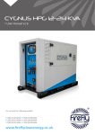
Pyxis Power Pack
User manual v3.2
For use with the following models:
PYX/800/250 PYX/800/250/S
PYX/400/250 PYX/400/250/S
PYX/BEM/110
PYX/800/250/1
PYX/400/250/1
PYX/800/250/1/S
PYX/400/250/1/S
www.fireflysolar.net
Table of Contents
1
1.1
1.2
1.3
1.4
1.5
1.6
1.7
1.8
Introduction
Foreword
Conventions
Warnings
Standards & Regulations
Disposal & Recycling
Firefly Contact Details
About Firefly
What’s In The Box?
2
2.1
2.1.1
2.1.2
2.1.3
2.2
2.3
2.4
2.4.1
2.4.2
2.4.3
Getting Started
Storage, Lifting & Positioning
Storage
Lifting
Positioning Before Using For The First Time
The Pyxis Control Panel
Connecting Pyxis
Earth attachment: Installing the Earth Rod
Connect The Input Connect The Output
8
8
8
8
8
8
9
10
10
11
11
3
3.1
3.1.1
3.1.2
3.1.3
3.2
3.2.1
3.2.2
3.2.3
3.2.4
3.2.5
General Operation
Turning The Power On
Monitoring the Power
Turning Off Pyxis
Disconnecting Pyxis
Charging Methods
Charging with AC/DC Mains Battery Charger
Connecting the supplied battery charger to a single Pyxis unit
Charging from 12 V DC Vehicle Accessory Socket
Charging with Fold-Array 360 Wp 12 V
Charging with Kinectrics PedGen
12
12
12
12
13
13
13
14
15
16
17
Page 2
Pyxis User Manual V3.2 with accessories
4
4
4
5
6
6
6
7
7
Table of Contents
3.3
3.3.1
3.3.2
3.3.3
3.3.4
3.4
Care And Maintenance
General Cleaning
Cooling Fan Maintenance
Caring For The Batteries
Testing Pyxis
Troubleshooting
17
17
18
19
19
20
4
4.1
4.1.1
4.1.2
4.1.3
4.1.4
Battery Extender Module
Introduction
Stacking
Connecting The First Battery Extender Module to Pyxis
Connecting Additional Battery Extender Modules to Pyxis
Charging Battery Extender Modules
21
21
21
22
22
22
5
5.1
5.2
5.2.1
Technical Information
Pyxis Run Times
Warnings
Safety Notice Regarding The Units’ Batteries
23
24
24
24
Figures
Fig. 1 - Control Panel
Fig. 2 - Earth Rod
Fig. 3 - AC Output Protection
Fig. 4 - Main Isolator
Fig. 5 - Inverter On/Off Switch
Fig. 6 - Battery Condition Indicator
Fig. 7 - The Cooling Fan
Fig. 8 - Removing The Cooling Fan Filter
Fig. 9 - Cooling Fan Filter Parts
Fig. 10 - Pyxis with Battery Extender Module
9
10
12
12
12
13
18
18
18
21
Pyxis User Manual V3.2 with accessories
Page 3
1
Introduction
1.1
Foreword
Firefly take this opportunity to congratulate you on receiving your new Pyxis
Power Pack.
Designed and manufactured within the United Kingdom using quality European
sourced electrical components, your new Pyxis offers sustainable power
generation with the reliability that you demand.
The purpose of this manual is to introduce you to Pyxis and provide you with a
guide to its safe installation and operation. This manual describes how your Pyxis
works, will help you with fault finding and examines what the key components
are doing and why.
1.2
Conventions
Throughout this user manual the following symbols are used:
WARNING
This symbol warns of the presence of a dangerous voltage
which could cause harm to the operator.
This symbol indicates the potential of harm to the operator,
damage to the unit or damage to connected devices.
This symbol indicates important or useful information.
Page 4
Pyxis User Manual V3.2 with accessories
The following terms are used in this manual to provide greater clarity:
• Firefly will be referred to as “The manufacturer”.
• The Pyxis Power Pack will be referred to as “Pyxis” or “Unit”.
• Any items that consume power will be referred to as “Consumers”.
1.3
Warnings
This user manual is an important part of Pyxis. It must be
kept available to all operators and kept close to the unit so
that it can be referred to at any time.
WARNING
When the unit is operating it generates potentially lethal
voltages. Work must only be performed on the unit by the
manufacturer or a qualified service engineer approved by
the manufacturer.
All items connected to the unit including distribution cables
and boxes should be regularly checked and adhere to the
same local regulations and standards as a regular grid-tied
mains installation.
Pyxis User Manual V3.2 with accessories
Page 5
1.4
Standards & Regulations
Pyxis conforms to the following standards and regulations:
•
•
•
•
•
•
•
•
Manufactured in compliance with ISO 9001:2008
LVD 2006/95/EC
2004/108/EC
765/2008/EC
768/2008/EC
BS 7671:2008
IEE 17th Edition Wiring Regulations
BS EN 60529:1992 Degree of Protection Provided by Enclosures Test
Procedure & Results
• Degree of Protection Provided by Enclosures is IP44
• 3418 - Electromagnetic Compatibility Regulations 2006:
• EN55022:2006, EN55014-1:2006, EN61000-6-4:2007, EN61000-4-3:2002,
EN61000-4-11:2004, EN61000-4-4:2004, EN61000-4-8:1993, EN61000-45:1995, EN61000-4-2:1995
1.5
Disposal & Recycling
Pyxis comprises of components that must disposed of responsibly. For the sake
of the environment many of the components within the unit can be recycled or
reused. Firefly will ensure the safe decommissioning and recycling of the unit at
no charge if the unit is returned to the manufacturer. Otherwise, please contact
the manufacturer for more information on safe and proper decommissioning
of your Pyxis.
1.6
Firefly Contact Details
Firefly Solar Generators Ltd.
Unit 20 Cliffe Industrial Estate
South Street
Lewes
East Sussex
BN8 6JL
United Kingdom
Page 6
Tel: +44 (0) 1273 40 95 95
Fax: +44 (0) 1273 40 95 96
E-mail: [email protected]
Web: www.fireflysolar.net
Pyxis User Manual V3.2 with accessories
1.7
About Firefly
Firefly is the market leading expert in the design and manufacture of off-grid,
portable Hybrid Power Solutions for temporary and permanent power
applications. Firefly has built its highly regarded reputation within the industry,
based on excellent customer service and product reliability. Founded in 2007 the
Company continues to develop innovative solutions to cater to the needs of its
ever growing customer sectors.
The Company offers green energy products and services that meet the needs of
environmentally concerned individuals and organisations internationally, that
are looking to reduce their carbon emissions caused by the use of fossil fuels
and diesel powered equipment. The unique range of renewable technology
solutions produce zero emissions, are truly silent running and eliminate the need
for fuel.
The systems are manufactured in the UK, under an ISO 9001:2008 approved
quality control system. Component suppliers are carefully selected to ensure
high levels of reliability and performance of the final product. Installation and
stringent testing is carried out to ensure compliance with EU and local legislation
where applicable.
1.8
What’s In The Box?
• Main Pyxis Unit
• AC/DC Mains Battery Charger
• User Manual
Pyxis User Manual V3.2 with accessories
Page 7
2
Getting Started
2.1
Storage, Lifting & Positioning
2.1.1
Storage
1. Pyxis is designed to be used and stored outside. However, to prevent
unnecessary weathering it is recommended that the unit is stored
inside when possible.
2. It is recommended that the battery bank is charged regularly while
in storage. Refer to “3.2 Charging Methods” on page 13 for further
information.
3. The main isolator and output protection switches should be switched
off when in storage and not being charged to prevent unnecessary
discharge of the battery bank.
2.1.2
Lifting
Pyxis is designed to be easily liftable without the need for lifting gear or
machinery.
It is recommended that either Pyxis or the Battery Extender are lifted from the
in-built handles by two persons.
2.1.3
Positioning
1. The unit must be positioned upright on a flat, solid surface. Ensure that
the unit is not at risk from being submersed in water.
2. Position the unit out of direct sunlight where possible.
The unit must remain upright at all times.
.
The unit may only be installed in accordance with the
requirements of IEC 60364-4-42
2.2
Before Using For The First Time
The unit’s internal battery should be charged before the unit is used for the first
time. Follow instructions in “3.2 Charging Methods” on page 13
Page 8
Pyxis User Manual V3.2 with accessories
2.3
The Pyxis Control Panel
1.
2.
3.
4.
5.
6.
7.
8.
Solar Isolator
AC Output Protection
Battery Condition Indicator
Inverter On/Off Switch
Solar Array Inputs
Solar Array Indicator
Main Isolator
Battery Extender Module
& 12 V DC Charging
9. Earth Point
10. AC Output Indicator
11. 230 V AC Output
Fig. 1 - Control Panel
Solar Isolator, Solar Array Inputs and Solar Array Indicator
are only available on units with the solar prep option.
Pyxis User Manual V3.2 with accessories
Page 9
2.4
Connecting Pyxis
WARNING
A protective earth must be connected to the earth
connection point on the unit’s front panel in compliance
with applicable local standards and regulations.
This can be done either by connecting to a suitable existing
electrical earth, or by using an earth rod available from the
manufacturer.
The minimum gauge of earth cable to be used is 2.5mm²
An earth rod is available from the manufacturer as an
accessory.
2.4.1
Earth attachment: Installing the Earth Rod
1. The Earth Point of Pyxis is located on the front panel “Fig. 1 - Control
Panel” on page 9.
2. Find a suitable place to drive the earth rod “Fig. 2 - Earth Rod” into the
ground. The earth rod should be driven down at least half way into the
ground using a mallet and placed as near to the unit as possible.
3. Check the earth cable is securely connected to the rod.
4. Undo the wing nut from the unit’s earth bolt and remove one of the
washers.
5. Slide the ring terminal at the end of the earth cable onto the earth bolt.
6. Replace the washer and securely tighten the nut.
Page 10
Pyxis User Manual V3.2 with accessories
Fig. 2 - Earth Rod
2.4.2
Connect The Input
There are a number of means available to charge the unit : AC/DC Mains Charger,
Vehicle Accessory Socket, Solar Fold-Array, Kinectrics PedGen. Further
information on connecting these items is available in section “3.2 Charging
Methods” on page 13.
Pyxis Battery Extender Modules are available to provide extended runtimes. Up
to three Battery Extender Modules can be connected to a single unit. Refer to “4
Battery Extender Module” on page 21 for further information.
2.4.3
Connect The Output
1. Before any power connections are made, ensure that the AC Output
Protection switch “Fig. 1 - Control Panel” on page 9 is switched Off.
2. Plug electrical consumers in to the 230 or 110 V AC Out socket on the
control panel “Fig. 1 - Control Panel” on page 9 using a 16 A CEE Form
industrial plug.
WARNING
Care must be taken to ensure that the correct connections
are made to avoid the risk of electrocution or possible
damage to the unit’s internal components.
The protection provided by the unit may be impaired If the
unit is not used in a manner specified by the manufacturer.
Ensure that the cumulative power of connected consumers
does not exceed the maximum power output of your unit.
Refer to the rating plate to ascertain the unit’s maximum
power output.
All connected consumers must be fit for purpose– refer to
their rating plates and manuals to ascertain the required
input.
Equipotential earth bonding should be used with other Class
I equipment including external battery cabinets.
Pyxis User Manual V3.2 with accessories
Page 11
3
General Operation
3.1
Turning The Power On
Once all connections are complete, the unit is ready to be switched on. For
location of switches see “Fig. 1 - Control Panel” on page 9
1. Switch on the AC Output Protection switch “Fig. 3 - AC Output
Protection”.
2. Switch on the unit using the Main Isolator Switch “Fig. 4 - Main
Isolator”.
3. Switch on the Inverter using the Inverter On/Off Switch push button.
See “Fig. 5 - Inverter On/Off Switch”.
4. The red LED indicator by the Inverter On/Off Switch and the green
AC Output Indicator see “Fig. 1 - Control Panel” on page 9 will
illuminate to indicate that the unit is now on and ready to supply
power to connected consumers.
3.1.1
Fig. 3 - AC Output Protection
Fig. 4 - Main Isolator
Monitoring the Power
An analogue battery condition indicator is provided see “Fig. 6 - Battery
Condition Indicator” on page 13 to give an overview of the internal battery’s
State Of Charge. For maximum life of the batteries it is recommended that the
system is not allowed to discharge below the yellow section of the gauge.
The Main Isolator switch “Fig. 4 - Main Isolator” must be in
the on position for the battery condition indicator to
operate.
3.1.2
Turning Off Pyxis
1. Switch off the Inverter using the Inverter On/Off Switch push button
“Fig. 5 - Inverter On/Off Switch”.
Page 12
Pyxis User Manual V3.2 with accessories
Fig. 5 - Inverter
On/Off Switch
3.1.3
Disconnecting Pyxis
1. Ensure that Pyxis is turned off “3.1.2 Turning Off Pyxis” on page 12.
2. Rotate the Main Isolator switch “Fig. 4 - Main Isolator” on page 12
to the off position.
3. Switch off the AC Output Protection switch “Fig. 3 - AC Output
Protection” on page 12.
4. Switch off the Solar Isolator switch if fitted “Fig. 1 - Control Panel” on
page 9.
5. Disconnect the input cable(s) “Fig. 1 - Control Panel” on page 9.
6. Disconnect the output cable(s) “Fig. 1 - Control Panel” on page 9.
7. Remove the earth cable by unscrewing the Earth Point wing nut.
8. Replace the washer and wing nut onto the Earth Point bolt “Fig. 1 Control Panel” on page 9.
3.2
Fig. 6 - Battery
Condition Indicator
Charging Methods
Pyxis can be charged using a number of methods: AC/DC Mains Charger, Vehicle
Accessory Socket, Solar Fold-Array or Kinectrics PedGen.
3.2.1
Charging with AC/DC Mains Battery Charger
The unit, connected Battery Extender Modules and individual Battery Extender
Modules can be charged via an external battery charger powered from either
the AC grid supply or a secondary power system.
The battery charger must be able to provide an amperage of at least 10% of the
Amp Hour (Ah) rating of the combined Pyxis & Battery Extender Modules that
are to be charged. Please contact the manufacturer for a suitable charger.
Pyxis User Manual V3.2 with accessories
Page 13
Do not use the unit while it is being charged from an
external battery charger. Otherwise damage to Pyxis and/or
external components could occur.
WARNING
Charging Pyxis with the wrong type of battery charger may
result in over-charging of the batteries and could cause
damage to the batteries and risk of injury to the user. Only
use a charger provided by the manufacturer.
3.2.2
Connecting the supplied battery charger to a single Pyxis unit
1. Connect the battery charger lead to the “Battery Extender Module
& 12 V DC Charging” socket on the front panel “Fig. 1 - Control Panel”
on page 9.
2. Follow the operation instructions included with the charger.
3. Battery charging and State Of Charge monitoring is handled by the
battery charger.
4. Disconnect the external battery charger when it indicates that the
battery is fully charged.
3.2.2.1 Charging the Pyxis while connected to one or more
Battery Extender Modules
The included battery charger provides enough power to
charge one unit individually. Higher output chargers suitable
for faster charging of Battery Extender Modules and multiple
units are available from the manufacturer as an accessory.
1. Connect the units using the included link leads.
2. Connect the battery charger to one of the connectors of the last unit in
the chain (it does not matter which is used).
Page 14
Pyxis User Manual V3.2 with accessories
3. The main unit and the Battery Extender Modules will be charged
simultaneously.
4. Battery charging and State Of Charge monitoring is handled by the
battery charger.
5. Disconnect the battery charger when it indicates that the batteries are
fully charged.
3.2.3
Charging from 12 V DC Vehicle Accessory Socket
A lead suitable for charging Pyxis from a vehicle is available from the
manufacturer as an accessory. Refer to instructions provided with the lead for
detailed instructions.
Ensure that the unit is safely secured to the vehicle if
charging while driving.
Charging Pyxis while the engine is not running can flatten the
vehicle’s battery.
3.2.3.1
Connecting
1. Start the vehicle’s engine.
2. Connect the large connector to the front panel of Pyxis.
3. Connect the small connector to the vehicle’s accessory socket.
3.2.3.2
Disconnecting
1. Disconnect the small connector from the vehicle’s accessory socket.
2. Disconnect the large connector from the front panel of Pyxis.
3. Stop the vehicle’s engine.
Pyxis User Manual V3.2 with accessories
Page 15
3.2.4
Charging with Fold-Array 360 Wp 12 V
(Only available on models with Solar Prep option)
3.2.4.1
Connecting
1. Once the array has been positioned suitably and the extension cables
safely run back to the unit, the array can be connected.
2. Before connecting the solar extension cables to Pyxis, ensure that the
Solar Isolator Switch “Fig. 1 - Control Panel” on page 9 is turned off.
3. Connect the array to the Solar Array Input on the control panel “Fig. 1 Control Panel” on page 9.
4. The LED indicator to the right of the inputs will illuminate to show that
the connection has been made.
5. Ensure that the extension cable connectors are fully engaged
to avoid the risk of them pulling out easily and possible
electrocution.
6. Once all connections are safely made, switch on the solar isolator
switch on the control panel “Fig. 1 - Control Panel” on page 9.
7. Ensure that the main isolator is switched on. Pyxis and connected
Battery Extender Modules will only charge from the solar input with
the main isolator in the on position.
8. The Battery Condition Indicator will move to the maximum position.
This indicates that the battery is being charged, it does not indicate
that the battery is full. (This indication is dependant on the Fold-Array
receiving sufficient direct sunlight).
3.2.4.2
Disconnecting
1. To disconnect the solar array from Pyxis, switch off the Solar Isolator
switch “Fig. 1 - Control Panel” on page 9.
2. Pull the Solar extension cables out from the control panel Solar Array
connectors “Fig. 1 - Control Panel” on page 9.
.
WARNING
Do not connect Firefly Solar Fold-Arrays with a total output
of more than 360 Wp and 12 V.
Page 16
Pyxis User Manual V3.2 with accessories
3.2.5
Charging with Kinectrics PedGen
3.2.5.1
Connecting
1. The equipment requires the use of an MC3 to Grey SB120 Anderson
lead for connecting the regulated output of the Kinectrics Equipment.
Please contact the manufacturer to obtain a suitable lead.
2. 1 x Kinectrics unit can be connected to Pyxis.
3. Once the Kinectrics equipment has been positioned suitably, the
extension cables connected and safely run back to Pyxis (please refer
to the Kinectrics PedGen User Manual for detailed setup information),
the equipment can be connected.
4. Ensure that the Main Isolator switch “Fig. 1 - Control Panel” on page
9 is in the Off position.
5. Connect the lead to the Battery Extender Module & 12 V DC Charging
connector on the Pyxis control panel “Fig. 1 - Control Panel” on page
9
6. Switch on the unit using the Main Isolator switch “Fig. 1 - Control
Panel” on page 9
3.2.5.2
Disconnecting
1. Switch off the unit using the Main Isolator switch “Fig. 1 - Control
Panel” on page 9
2. Disconnect all input cables.
3.3
Care And Maintenance
3.3.1
General Cleaning
1. Minor cleaning should be performed using a damp microfibre cloth.
2. Detergents or chemicals should not be used.
WARNING
Do not use a hose or pressure washer to clean Pyxis or
Battery Extender Modules.
Pyxis User Manual V3.2 with accessories
Page 17
3.3.2
Cooling Fan Maintenance
3.3.2.1
Removing The Cooling Fan Dust Filter
1. Remove the outer cover by grasping both sides and pulling straight
outwards “Fig. 8 - Removing The Cooling Fan Filter” on page 18.
2. Remove the plastic mesh and white filter material from the cover.
3.3.2.2
Checking The Cooling Fan Dust Filter
In normal operating conditions the cooling fan dust filter must be checked at
least monthly. When the unit is being used in dusty or sandy environments it
should be checked at least weekly. To check the dust filter:
1. Remove the Dust Filter “3.3.2.1 Removing The Cooling Fan Dust Filter”
2. Visually inspect the mesh and filter element for debris, dust or sand.
3.3.2.3
Fig. 7 - The Cooling Fan
Cleaning The Dust Filter
3. Any debris and dust should be removed and/or cleaned from the filter
by brushing or light vacuuming.
4. If the filter element becomes damaged or is soiled beyond cleaning,
replacement is necessary. Contact the manufacturer for replacement
filter elements.
Fig. 8 - Removing The
Cooling Fan Filter
Operating the unit without a correctly fitted Dust Filter may
allow the ingress of dust particles and potentially damage
internal components..
3.3.2.4
Replacing The Dust Filter
1. Re-assemble the Dust Filter assembly with the black mesh towards the
outside of the unit
2. Insert the white filter element into the outer cover.
3. Re-attach the Dust Filter assembly by grasping the outer cover and
pushing it firmly back into position over the fan until it clicks into
position.
4. Ensure that the black mesh is visible from outside the unit and that the
white filter element is positioned correctly covering all inlet holes.
Page 18
Pyxis User Manual V3.2 with accessories
Fig. 9 - Cooling Fan
Filter Parts
3.3.3
Caring For The Batteries
Pyxis uses sealed, maintenance free batteries. The only routine care necessary
is to ensure that when not in use, the unit and any Battery Extender Modules
are charged at least once a month to keep the battery bank topped up. Refer to
“3.2 Charging Methods” on page 13 for further information.
Leaving the batteries in a state of discharge for extended
periods will seriously affect their performance.
3.3.4
Testing Pyxis
It is recommend that the unit should be tested annually for electrical safety by
a qualified electrician.
Local regulations may require more frequent testing. Please refer to local
regulations for further details.
WARNING
If Pyxis fails the relevant tests, do not use or open the unit.
It must only be opened by a qualified service engineer.
It is recommended that a full service is performed every two years in order to
ascertain the condition of your system. Please contact the manufacturer for
further information.
Pyxis User Manual V3.2 with accessories
Page 19
3.4
Troubleshooting
Issue
Possible Cause(s)
The Main Isolator switch is
on, but the consumers are
not receiving any power
The AC Output Protection
may not be switched on
Suggestion
Check that the AC Output
Protection Switch “Fig. 1 Control Panel” on page 9
is pushed up to the on
position.
There is an electrical fault
with the consumers
connected to the AC
output
Check the electrical integrity
of the wiring and consumers
being connected to the
unit’s AC output.
Connected consumers are
drawing too much power for
the rated output of the unit
Refer to the maximum
output rating on the unit’s
rating plate and reduce the
total power draw
accordingly.
When switching the Inverter
on with the Inverter On/Off
switch, its red LED
illuminates, but the green
AC Output Indicator does
not illuminate.
The AC Output Protection
Switch is in the off position.
Switch the AC Output
Protection Switch “Fig. 1 Control Panel” on page 9
into the on position. (Check
above points if the AC
Output Protection switch
continues to trip.)
Input (e.g. battery charger,
solar array) is connected
and operating correctly but
the batteries are not being
charged.
The Main Isolator switch is
in the off position.
Switch the Main Isolator
switch “Fig. 1 - Control
Panel” on page 9 into
the on position.
The AC Output Protection
Switch (“Fig. 1 - Control
Panel” on page 9) keeps
tripping
Page 20
Pyxis User Manual V3.2 with accessories
4
Battery Extender Module
4.1
Introduction
The Pyxis Battery Extender Module is available separately from the
manufacturer, providing extended run times for Pyxis.
4.1.1
Stacking
Interlocking corners are featured on both Pyxis and the Battery Extender
Modules, allowing up to three Battery Extender Modules to be safely stacked
with Pyxis “Fig. 10 - Pyxis with Battery Extender Module” on page 21.
Do not stack more than one Pyxis and three Battery
Extender Modules (four units in total)
Fig. 10 - Pyxis with Battery
Extender Module
Pyxis User Manual V3.2 with accessories
Page 21
4.1.2
Connecting The First Battery Extender Module to Pyxis
1. An interconnecting link lead is supplied with each Battery Extender
Module.
2. Connect one end of the link lead to the Battery Extension & 12 V DC
Charging connector on the Pyxis control panel.
3. Connect the other end of the link lead to one of the Battery Extender
Module 12 V DC In/Out connectors (it does not matter which is used.)
It is possible to connect and disconnect the Battery Extender
Module while the Pyxis unit is providing power to
consumers. This allows “hot swapping” of Battery Extender
Modules.
4.1.3
Connecting Additional Battery Extender Modules to Pyxis
1. A link lead is supplied with each Battery Extender Module.
2. Connect one end of the interconnecting cable to the Battery Extension
& 12V DC Charging connector on Pyxis
3. Connect the other end to one of the Battery Extender Module 12 V DC
In/Out connectors (it does not matter which is used.)
4.1.4
Charging Battery Extender Modules
Battery Extender Modules can be charged while connected to Pyxis or on their
own. Multiple Battery Extender Modules can be charged simultaneously by
connecting them together using the interconnecting cable. Refer to “3.2 Charging
Methods” on page 13 for further information.
Page 22
Pyxis User Manual V3.2 with accessories
5
Technical Information
Model
Pyxis Technical Information
PYX/400/250
PYX/800/250
Continuous Output @ 25°c
350 W
700 W
Peak Power Output @ 25°c
700 W
1400 W
Max Power Output (3 Minutes)
400 W
800 W
Output Voltage
(Pure Sine Wave)
230 V AC (110 V AC Option Available)
Output Frequency
50 Hz
Solar Power Input Nominal
Voltage Range¹
12 V - 21 V
Solar Array Power Input Limit¹
360 Wp
Solar Array Input Current Limit¹
30 A
Solar charge algorithm¹
PWM
12 V DC Input/Output Current
Limit
75 A
Standby Power Consumption
3.1
3
Battery Storage Type
AGM
Battery Bank Voltage
12 V
Battery Bank Capacity
40 Ah (C20)
AC Power Output Connection
1 x 16 A 230 V SP CEE Form Socket
Solar Power Input Connection¹
Multi-Contact 30 A MC3
DC Input/Output Connection
1 x 120 A 12 V DC Grey SB120 Anderson
Inverter Protection
Short Circuit, Inverse Polarity, Overload,
Overheat, Low Battery
Circuit Protection
RCBO 230 V AC: 6 A / 110 V AC: 10 A
Earth Fault Protection
RCBO 230 V AC: 6 A / 110 V AC: 10 A
Battery Monitoring
Battery Condition Indicator/ Analogue
Set up time
5 minutes
Water/Ingress Protection
IP44
Operating Temperature Range
-10°c - 45°c
Dimensions (WxDxH)
560mm x 350mm x 340mm
Packaged Dimensions (WxDxH)
670mm x 460mm x 550mm
Weight (kg)
Packaged Weight (kg)²
Recommended number of
persons for lifting
Warranty
28
29
32.4
33.4
2
2 Years
¹ - Only available on models with Solar
Prep option
² - For models with Solar Prep option,
add 1 kg
Pyxis User Manual V3.2 with accessories
Page 23
Pyxis Battery Extender Module Technical Information
Model
PYX/BEM/750
Battery Storage Type
AGM
Battery Bank Voltage (V)
12
Battery Bank Capacity (Ah)
110 (C20)
DC Input/Output Connection
2 x 120 A 12 V DC Grey SB120 Anderson
Setup Time
1 Minute
Water/Ingress Protection
IP44
Operating Temperature Range
-10°c - 45°c
Dimensions (W x D x H)
560 mm x 350 mm x 340 mm
Packaged Dimensions (W x D x H)
720 mm x 495 mm x 485 mm
Weight (kg)
40.5
Packaged Weight (kg)
44.89
Recommended no of persons for lifting
Warnings
5.2.1
Safety Notice
Regarding The Units’
Batteries
Servicing of the batteries should be
performed or supervised by
personnel knowledgeable about
batteries and required precautions.
When replacing batteries, replace
with the same type and number of
batteries.
2
Warranty
5.1
5.2
2 Years
Pyxis Run Times
Pyxis Run Times* (No External Charge)
Model
PYX/400/250
PYX/400/250
+ Battery
Extender
PYX/400/250
+ 2 x Battery
Extenders
PYX/800/250
PYX/800/250
+ Battery
Extender
PYX/800/250
+ 2 x Battery
Extenders
Run Time at 100 W Output e.g. Plasterer’s Light, Laptop, 55” Smart TV
2:40
10:00
17:30
2:40
10:00
17:30
Run Time at 200 W Output e.g. 18 V Cordless Drill Fast Charger, Desktop PC & Monitor
1:15
5:00
8:40
1:15
5:00
CAUTION: Do not dispose of
batteries in a fire. The batteries
may explode.
CAUTION: Do not open or
mutilate batteries. Released
electrolyte is harmful to the skin
and eyes. It may be toxic.
8:40
Run Time at 300 W Output e.g. Oscillating Multi-Tool, Kitchen Food Blender
0:30
2:50
5:10
0:30
2:50
5:10
Run Time at 500 W Output e.g. SDS Hammer Drill, Wall Mounted Heater
-
-
-
0:20
1:40
3:00
* (Hours:Minutes), all run times are approximate
Scan to view the Pyxis video online. Alternatively, use this link:
www.fireflysolar.net/pyxis-video
Page 24
Pyxis User Manual V3.2 with accessories
E & OE,
©2014 Firefly Solar Generators Ltd.
[email protected]
www.fireflysolar.net
+44 (0)1273 40 95 95
Pyxis Power Pack
Accessories and Spares
Available to order from Firefly. Tel +44 (0) 1273 40 95 95
Pyxis Power Pack™ Power Storage Extender
Increase Battery Storage capacity
Storage capacity for Pyxis Power Pack™ can be rapidly increased by simply
adding stackable Battery Power Storage Extender modules. Each of the modules
is linked using simple “plug and play” connections and is “hot swappable”
allowing Battery Extender modules to be added or removed without interrupting
the output of the Pyxis Power Pack™.
Power Storage Extender
12 V DC Vehicle Accessory Socket
Fold-Array 360 Wp 12V (FOL/360/4/12)
16 A Plug to 13 A Adapter (in-line) 4-Way 230 V
5m 16 A Extension Cable 110 V / 230 V
10m 16 A Extension Cable 110 V / 230 V
Earth Rod with Clamp & 1m Earth Cable
0.5 Interconnect cable 120 A 12 V DC Grey SB120 Anderson for extender
15 A 12 V DC Battery Charger 13 A 230 V AC Fast Charge Upgrade
Pack of 5 Cooling Fan Filter Elements
View Video:
Firefly Solar Generators Ltd
The experts in Hybrid Power since 2007
T +44 (0) 1273 409595 E [email protected] W www.fireflysolar.net
Unit 20, Cliffe Industrial Estate, South Street, Lewes, East Sussex BN8 6JL UK