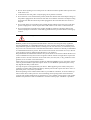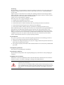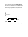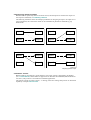
1
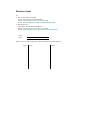
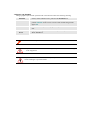
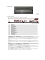
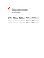
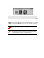
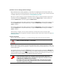
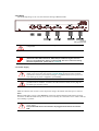
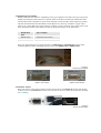
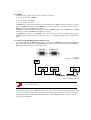
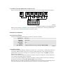
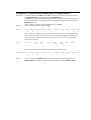
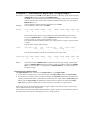
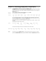
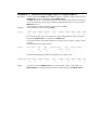
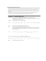
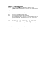
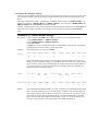
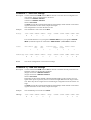
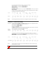
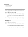
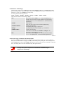
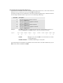
DOC-3200-2
User's Manual
DOC-3200-2, Current Version
Title:
ID-no.:
Date:
chapter 1
chapter 2
chapter 3
chapter 4
chapter 5
chapter 6
chapter 7
new:
corr.:
add.:
HERMES DXD – User’s Manual
DOC-3200-2
2003-09
main issue
new
new
new
new
new
new
new
update
The corresponding chapters are new or completely revised.
Passages of the corresponding chapter were corrected; see modification bars.
Passages of the corresponding chapter were added; see modification bars.
Document History
Modifications which result in a new version are indicated by a vertical bar.
Keep this sheet!
Trademarks
Brand and product names mentioned in this manual may be trademarks, registered trademarks or
copyrights of their respective holders. All brand and product names mentioned in this manual
serve as comments or examples and are not to be understood as advertising for the products or
their manufacturers.
Copyright © 1999 - 2003 by Barco Control Rooms GmbH
Die Weitergabe sowie die Vervielfältigung aller Unterlagen, die von uns überlassen werden, deren
Verwertung und Mitteilung ihres Inhaltes an Dritte ist nicht gestattet, soweit dies nicht ausdrücklich zugestanden ist. Urheberrechte, insbesondere auch solche an Software, werden nur insoweit
übertragen, als es für die Erreichung des speziellen Vertragszwecks erforderlich ist. Zuwiderhandlungen können zu Schadensersatz verpflichten. Alle Rechte aus der Erteilung eines Patents
oder der Eintragung eines Gebrauchsmusters verbleiben bei uns.
Copyright © 1999 - 2003 by Barco Control Rooms GmbH
All rights reserved. No part of this document may be copied, reproduced or translated. It shall not
otherwise be recorded, transmitted or stored in a retrieval system without the prior written consent
of Barco Control Rooms GmbH.
Guarantee and Compensation
Barco Control Rooms GmbH provides a guarantee relating to perfect manufacturing as part of the
legally stipulated terms of guarantee. On receipt, the purchaser must immediately inspect all delivered goods for damage incurred during transport, as well as for material and manufacturing faults.
Barco Control Rooms GmbH must be informed immediately in writing of any complaints.
The period of guarantee begins on the date of transfer of risks, in the case of special systems and
software on the date of commissioning, at the latest 30 days after the transfer of risks. In the event
of justified notice of complaint, Barco Control Rooms GmbH can repair the fault or provide a replacement at its own discretion within an appropriate period. If this measure proves to be impossible or unsuccessful, the purchaser can demand a reduction in the purchase price or cancellation of
the contract. All other claims, in particular those relating to compensation for direct or indirect
damage, and also damage attributed to the operation of software as well as to other services provided by Barco Control Rooms GmbH, being a component of the system or independent services,
will be deemed invalid provided the damage is not proven to be attributed to the absence of properties guaranteed in writing or due to the intent or gross negligence on the part of Barco Control
Rooms GmbH
If the purchaser or a third party carries out modifications or repairs on good delivered by Barco
Control Rooms GmbH, or if the goods are handled incorrectly, in particular if the systems are
commissioned or operated incorrectly or if, after the transfer of risks, the goods are subject to influences not agreed upon in the contract, all guarantee claims of the purchaser will be rendered invalid. Not included in the guarantee coverage are system failures which are attributed to programs
or special electronic circuitry provided by the purchaser, e. g. interfaces. Normal wear as well as
normal maintenance are not subject to the guarantee provided by Barco Control Rooms GmbH either.
The environmental conditions as well as the servicing and maintenance regulations specified in
this manual must be complied with by the customer.
Revision sheet
To:
Barco Control Rooms GmbH
An der Rossweid 5, D-76229 Karlsruhe
Phone: +49-721-6201-0, Fax: +49-721-6201-298
E-mail: [email protected] Web: www.barcocontrolrooms.de
BarcoProjection
Noordlaan5, B-8520 Kuurne, Belgium
Phone: (32) (56) 36-8211, Fax: (32) (56) 36-8251
E-mail: [email protected] , Web: www.barcocontrolrooms.com
From:
Date:
Please correct the following points in the documentation mentioned above:
page
wrong
correct
Table of Contents
1 Preliminary Remarks.................................................................................................................... 1-1
1.1 How this manual is organized ............................................................................................. 1-2
1.2 Styles and Symbols ............................................................................................................. 1-3
1.3 Safety Information............................................................................................................... 1-4
1.3.1 Precautions.................................................................................................................. 1-6
1.3.2 Unpacking of Devices ................................................................................................ 1-6
1.3.3 Transport of Devices .................................................................................................. 1-6
1.3.4 Modification of Devices ............................................................................................. 1-6
2 Summary ...................................................................................................................................... 2-1
2.1 Connecting the graphical controller and the projection cubes ............................................ 2-2
2.2 Assigning inputs to outputs ................................................................................................. 2-3
2.3 Remote Control ................................................................................................................... 2-3
3 Getting started .............................................................................................................................. 3-1
3.1 Examining ........................................................................................................................... 3-2
3.1.1 The Front Panel .......................................................................................................... 3-2
3.1.2 The Back Panel ........................................................................................................... 3-4
3.2 Native device settings (default settings).............................................................................. 3-5
3.3 DDC Capability................................................................................................................... 3-5
3.4 Cabling ................................................................................................................................ 3-6
3.4.1 Power Supply.............................................................................................................. 3-6
3.4.2 Digital Input and Output............................................................................................. 3-7
3.4.3 Remote Control........................................................................................................... 3-7
3.5 Operating Hermes DXD...................................................................................................... 3-8
4 Remote Control ............................................................................................................................ 4-1
4.1 Cabling ................................................................................................................................ 4-2
4.1.1 Cabling of Hermes DXD (number of devices < 20) .................................................. 4-2
4.1.2 Cabling of Hermes DXD (number of devices > 20) .................................................. 4-3
4.2 Definition of Protocol.......................................................................................................... 4-3
4.2.1 Connection Settings .................................................................................................... 4-3
4.2.2 Communication .......................................................................................................... 4-3
4.2.3 Structure of Messages................................................................................................. 4-4
4.2.4 Acknowledge .............................................................................................................. 4-4
4.2.5 Types of RCS Classes................................................................................................. 4-5
4.3 How to calculate the checksum........................................................................................... 4-5
4.4 The Status Register.............................................................................................................. 4-6
5 Controlling Hermes DXD ............................................................................................................ 5-1
5.1 Valid Commands for Hermes DXD .................................................................................... 5-2
5.2 Request commands.............................................................................................................. 5-3
5.3 Switching commands .......................................................................................................... 5-4
5.3.1 Switching the Digital Output 1................................................................................... 5-4
5.3.2 Switching the Digital Output 2................................................................................... 5-6
5.4 Enabling/Disabling auto switch .......................................................................................... 5-9
5.5 Commands referring to settings ........................................................................................ 5-11
5.6 Reading the status register................................................................................................. 5-14
5.7 Reading the product identification .................................................................................... 5-15
5.8 Error messages .................................................................................................................. 5-16
6 Broadcast addressing mode.......................................................................................................... 6-1
6.1 Structure of message ........................................................................................................... 6-2
6.2 Processing a command in broadcast mode.......................................................................... 6-2
6.3 Commands for broadcast addressing................................................................................... 6-3
7 Technical Data ............................................................................................................................. 7-1
7.1 General Data........................................................................................................................ 7-2
7.1.1 Dimensions ................................................................................................................. 7-2
7.1.2 Power Supply.............................................................................................................. 7-2
7.1.3 Operating Conditions.................................................................................................. 7-3
7.2 Interfaces ............................................................................................................................. 7-4
7.2.1 Remote In.................................................................................................................... 7-4
7.2.2 Remote Out................................................................................................................. 7-4
7.2.3 Digital In..................................................................................................................... 7-5
7.2.4 Digital Out .................................................................................................................. 7-5
7.3 Parts List.............................................................................................................................. 7-6
7.3.1 Hermes DXD .............................................................................................................. 7-6
7.3.2 Remote Control........................................................................................................... 7-6
7.3.3 User’s Manuals ........................................................................................................... 7-6
7.4 Address ................................................................................................................................ 7-7
1 Prelim inary Remarks
This User’s Manual describes design, function and operation of HERMES DXD of Barco.
HERMES DXD is a multiplexer to connect each of two digital projection units alternatively to two
graphical controllers. Barco's product range of digital projection units comprises projection modules of the OVERVIEW D series and of the OVERVIEW P series, the graphical controller could be an
EOS or an ARGUS device. For further orientation on HERMES DXD see chapter 2 Summary, please!
This chapter explains the structure of the manual itself and the used typographic styles and symbols. Safety information is provided concerning the operation of systems from Barco.
1.1 How th is manual is organized
This manual is divided into seven chapters:
Preliminary Remarks
explains the structure of the manual itself and the used typographic styles and symbols. Safety information is provided concerning the operation of systems from Barco.
Summary
provides a summary of the system components and characteristics.
First steps
describes the interfaces and the cabling of HERMES DXD.
Remote Control
describes cabling, protocol and addressing procedure of the remote control.
Operating Hermes DXD
describes the syntax of the commands and their consequences
Broadcast addressing mode
describes how to address all devices and the valid commands
Technical Data
provides tabular overviews about the technical details of the HERMES DXD
Numbering
Chapters, pages, figures and tables are numbered separately. Chapters are indicated by a »point
syntax«, e. g. 4.2.3, pages by a »dash syntax«, e. g. 2-1, as figures and tables are, e. g. Figure 5-4.
1.2 Styles and Symbols
The typographic styles and the symbols used in this document have the following meaning:
Arial bold
Labels, menus and buttons are printed in the Arial bold font.
Condensed
Links to both other chapters of this manual and to sites in the Internet are
printed condensed. In the on-line version of this manual all hyperlinks
appear teal.
Courier
Names of files and parts from programs are printed in the Courier
font.
Courier
bold
Inputs you are supposed to do from the keyboard are printed in Courier bold font.
This arrow marks tips and notes.
If you do not heed instructions indicated by this symbol there is a risk of damage
to the equipment!
If you do not heed instructions indicated by this symbol there is a risk of electrical
shock and danger to personal health!
1.3 Safety Information
This section describes safety precautions which must be observed when installing a product from
BARCO.
HERMES DXD is built in accordance with the requirements of the international safety standard
IEC950, UL1950 and CSA C22.2 No. 950, which are the safety standards of information technology equipment including electrical business equipment.
The safety standards of information technology equipment impose important requirements on the
use of safety critical components, materials and isolation, in order to protect the user or operator
against the risk of electric shock and energy hazard, and having access to live parts.
Safety standards also impose limits to the internal and external temperature rises, radiation levels,
mechanical stability and strength, enclosure construction and protection against risk of fire.
Simulated single fault condition testing ensures the safety of the equipment to the use even when
the equipment’s normal operation fails.
General safety instructions
All the safety and operating instructions should be read before using this unit.
The operating instructions manual should be retained for future reference.
All warnings on the device and in the documentation manuals should be adhered to.
All instructions for operating and use of this equipment must be followed precisely.
Installation and Service
Installation and preliminary adjustments should be performed by qualified BARCO personnel or
authorized BARCO service dealers.
On Safety
Check the power rating on your outlet before connecting the devices to the
wall outlet or to a power strip. Contact your facilities manager or a qualified
electrician if you are not sure what type of power is supplied to your building.
The devices are designed to operate with single-phase power systems having
a grounded neutral conductor. To reduce the risk of electrical shock, do not
plug into any other type of power system.
A. Mains lead (AC Power cord) with CEE 7 plug:
The colors of the mains lead are colored in accordance with the following code:
Green-and-yellow:
Earth (safety
earth)
Blue:
Neutral
Brown:
Line (live)
B. Power cord with ANSI 73.11 plug:
The wires of the power cord are colored in accordance with the following code:
Green/yellow:
Ground
White:
Neutral
Black:
Line (live)
Do not allow anything to rest on the power cord. Do not locate this product where persons will
walk on the cord.
To disconnect the cord, pull it out by the plug. Never pull the cord itself.
If an extension cord is used with this product, make sure that the total of the ampere ratings on
the products plugged into the extension cord does not exceed the extension cord ampere rating.
Also make sure that the total of all products plugged into the wall outlet does not exceed 15
amperes.
Never push objects of any kind into this product through cabinet slots as they may touch dangerous voltage points or short out parts that could result in a risk of fire or electrical shock.
Never spill liquid of any kind on the product. Should any liquid or solid object fall into the
cabinet, unplug the set and have it checked by qualified service personnel before resuming operations.
Warning: Do Not Place Flammable or Combustible Materials Near Device!
BARCO products are designed and manufactured to meet the most stringent safety regulations.
Exposing flammable or combustible materials into close proximity of this device could result in
the spontaneous ignition of that material, resulting in a fire. For this reason, it is absolutely necessary to leave an "exclusion zone" around all external surfaces of the device whereby no flammable
or combustible materials are present. The exclusion zone must be not less than 10 cm (4"). Do not
cover the device with any material while the device is in operation.
Keep flammable and combustible materials away from the device at all times. Mount the device in
a well ventilated area away from sources of ignition and out of direct sun light. Never expose this
product to rain or excessive moisture. In the event of fire, use sand, CO2, or dry powder fire extinguishers; never use water on an electrical fire.
Always have service performed on this product by authorized BARCO service personnel. Always
insist on genuine BARCO replacement parts. Never use non-BARCO replacement parts as they
may degrade the safety of this device.
Use only the power cord supplied with your device. While appearing to be similar, other power
cords have not been safety tested at the factory and may not be used to power the device. For a replacement power cord, contact your dealer.
Slots and openings in the cabinet and the sides are provided for ventilation; to ensure reliable operation of the device and to protect it from overheating, these openings must not be blocked or
covered. This product should never be placed near or over a radiator or heat register. This product
should not be placed in a built-in installation or enclosure unless proper ventilation is provided.
On Servicing
Do not attempt to service this device yourself, as opening or removing covers may expose you to
dangerous voltage potential and risk of electric shock! Refer all service to a qualified BARCO
service center.
Adjust only those controls that are covered by the operating instructions since improper adjustment of the other controls may result in damage and will often require extensive work by a qualified technician to restore the product to normal operation.
Call for service in the following conditions :
When the power cord or plug is damaged or frayed.
If liquid has been spilled into the device.
If the product has been exposed to rain or water.
If the product does not operate normally when the operating instructions are followed.
If the product has been dropped or the cabinet has been damaged;
If the product exhibits a distinct change in performance, indicating a need for service.
When replacement parts are required, be sure the service technician has used original BARCO replacement parts or authorized replacement parts which have the same characteristics as the
BARCO original part. Unauthorized substitutions may result in degraded performance and reliability, fire, electric shock or other hazards. Unauthorized substitutions may void warranty.Upon
completion of any service or repairs to this unit, ask the service technician to perform safety
checks to determine that the unit is in proper operating condition.
1.3.1 Precaut ions
For your own protection, observe the following safety precautions when installing your device!
Observe all warnings and instructions printed on the devices!
Check that the voltage and frequency of your power supply match those printed on the device
label with the rated electrical values!
Servicing not explicitly mentioned in this manual should never be carried out by unauthorized
personnel!
1.3.2 Unpack ing of Devices
Note advises on the packaging for unpacking!
1.3.3 Transpo rt of Devices
Devices shall be transported in their original packaging only. Note advises on the packaging for
transport!
1.3.4 Modific ation of Devices
Mechanical or electrical modifications others than described in this manual must not be made to
the devices. Barco is not liable for damages resulting from modified devices.
Only authorized personnel should carry out other maintenance work not explicitly
mentioned in this manual!
Never open the case of HERMES DXD without first disconnecting the power supply cord! Measurements and tests with the opened device may be carried out only
in the factory or by specially trained personnel, due to the dangers of electrical
shock.
2 Summ ary
This chapter gives an overview of the HERMES DXD.
2.1 Conne cting the graphical controller and the projection cubes
HERMES DXD is equipped with two digital input connectors (Digital In 1, Digital In 2) and two
digital output connectors (Digital Out 1, Digital Out 2).
The output connectors can be routed to any input connector, resulting in the following fields of
applications:
Hermes DXD as multiplexer
The connection of the projection cubes to different types of graphical controllers via HERMES
DXD allows controlling the Display Wall by different operating systems. Some cubes or the entire
Display Wall can alternatively be used as Windows NT desktop or as root window (X Window
system).
Redundancy
Some fields of application require the connection of the projection cubes to identical graphical
controllers: In a case of malfunction of one graphical controller it is immediately switched to the
other graphical controller. This redundancy guarantees a permanent availability of the Display
Wall.
Splitter
It is also possible to apply one signal to both outputs and thus display the identical information on
two different projection cubes.
Repeater
To increase the distance between graphical controller and projection unit, HERMES DXD can be
used as a two channel repeater.
Controller 1
Input 1
Output 1
projection
module 1
Controller 2
Input 2
Output 2
projection
module 2
Figure 2-1
connecting Hermes DXD (schematics)
2.2 Assign ing inputs to outputs
HERMES DXD is operated by means of remote control, and the inputs are routed to the output via
the respective command, cf. 5.3 Switching commands.
The following schematics show the multiple possibilities for assigning an input to an output. For a
clear arrangement, the connections which can be established in parallel are indicated by gray
dashed lines.
Input 1
Output 1
Input 1
Output 1
Input 2
Output 2
Input 2
Output 2
Input 1
Output 1
Input 1
Output 1
Input 2
Output 2
Input 2
Output 2
Figure 2-2
assigning inputs to output
2.3 Remot e Control
HERMES DXD is controlled by a serial interface. The remote control is integrated in X Window
(see 7.3.3 User’s Manuals) and available as application for Windows NT/2000/XP (HERMES REMOTECONTROL). The protocol is accessible for individual applications.
The general concept of remote control, i. e. cabling, connection settings and protocol are described
separately in chapter 4 Remote Control.
3 Gettin g started
This chapter describes the control elements and interfaces of HERMES DXD as well as the cabling.
3.1 Examin ing
Figure 3-1
Hermes DXD
3.1.1 The Fro nt Panel
The front panel of your HERMES DXD looks like this or similar:
REMOTE IN
REMOTE OUT
1
2
DIGITAL IN 1
3
4
DIGITAL IN 2
5
6
DIGITAL OUT 1
7
8
DIGITAL OUT 2
9
10
POWER
11
Figure 3-2
Front Panel of Hermes DXD
1
2
3
4
5
6
7
8
9
10
11
REMOTE IN
REMOTE OUT
LED: DIGITAL IN 1
DIGITAL IN 1
LED: DIGITAL IN 2
DIGITAL IN 2
LED: DIGITAL OUT 1
DIGITAL OUT 1
LED: DIGITAL OUT 2
DIGITAL OUT 2
LED: POWER
The REMOTE IN socket [1] is for plugging in the remote control cable coming from the previous device
(or the controlling PC), the REMOTE OUT [2] for the cable leading to the next device.
The DIGITAL IN 1 socket [4] is for connecting HERMES DXD with the graphic card of a graphical controller. The DVI cable is plugged in here. If a signal is applied to DIGITAL IN 1, the LED [3] is green,
else off.
The DIGITAL IN 2 socket [6] is for connecting HERMES DXD with the graphic card of a graphical controller. The DVI cable is plugged in here. If a signal is applied to DIGITAL IN 2, the LED [5] is orange,
else off.
The DIGITAL OUT 1 socket [8] is for connecting HERMES DXD with the projection unit of a Barco projection cube. If the signal of DIGITAL IN 1 is applied to DIGITAL OUT 1, the LED [7] is green, if the signal of DIGITAL IN 2 is applied to DIGITAL OUT 1, the LED [7] is orange.
The DIGITAL OUT 2 socket [10] is for connecting HERMES DXD with the projection unit of a Barco
projection cube. If the signal of DIGITAL IN 1 is applied to DIGITAL OUT 2, the LED [9] is green, if the
signal of DIGITAL IN 2 is applied to DIGITAL OUT 2, the LED [9] is orange.
The LED POWER [11] indicates the device is switched on and operating properly. If the LED is off,
HERMES DXD is switched off or the internal logic control has detected an error.
LEDs allocated to the inputs:
If they are off, there is no signal present. If there is a sync signal present, the LED is
on:
Green stands for (signal present on) input (channel) 1
Orange stands for (signal present on) input (channel) 2
LEDs allocated to the outputs:
The color of the LED indicates which input (channel) is displayed:
In case it is green, input 1 is displayed via the respective output
In case it is orange, input 2 is displayed via the respective output
Color LED
LED input 1
LED input 2
off
No Signal present
No Signal present
LED output 1
LED output 2
green
Signal present
-
output 1 routed to
input 1
output 2 routed to
input 1
orange
-
Signal present
output 1 routed to
input 2
output 2 routed to
input 2
3.1.2 The Bac k Panel
The back panel of your HERMES DXD looks like this or similar:
A
A
B
C
B
C
Main Switch
AC In
AC Out
Figure 3-3
The Main Switch [A] is for switching HERMES DXD on and off. If the 0 is visible on top of the switch,
the device is switched off, and it can be switched on by pressing the switch.
The AC In socket [B] is for connecting to a power supply as specified in section 7.1.2 Power Supply.
The AC Out socket [C] is for connecting further devices (of type HERMES DXD only!) to the power supply. AC Out is connected directly to AC In and is live as soon as AC In is connected to a power supply.
Up to max. ten HERMES DXD devices can be put on top of each other. Thus you can
group the devices into towers next to each other, e. g., in the same order as the projection cubes are arranged.
To protect HERMES DXD from overheating, the air supply openings in the case must
not be covered! If you group the devices into towers standing next to each other a
space between the devices not less than 10 centimeter must be kept!
3.2 Native device settings (default settings)
Hermes DXD has auto switch capabilities: in case there is no signal present at the input routed to an
output, the output may switch automatically to the other input. Per default, this auto switch functionality
is enabled. If desired, it can be deactivated, cf. Enabling/Disabling auto switch
Having two graphic channels connected to HERMES DXD, and none of them specified as input source,
the channel connected to DIGITAL IN 1 is selected as signal for DIGITAL OUT 1, and the channel connected to DIGITAL IN 2 is selected as signal for DIGITAL OUT 2.
If no signal is detected on the graphic channel connected to DIGITAL IN 1, then the graphic channel connected to DIGITAL IN 2 is selected automatically as input for DIGITAL OUT 1 instead, provided auto
switch is enabled
If no signal is detected on the graphic channel connected to DIGITAL IN 2, then the graphic channel connected to DIGITAL IN 1 is selected automatically as input for DIGITAL OUT 2 instead, provided auto
switch is enabled.
After cabling is complete you can switch on the device with the main switch on the back panel.
Switching between the two graphical controllers is done by means of the remote control (see chapter 5.3
Switching commands.
3.3 DDC C apability
HERMES DXD has DDC capability, i.e. it reads the timing of the connected projection module.
It is mandatory that the projection units connected to the two outputs of a Hermes
DXD are all of the same type, e.g. OverView D
HERMES DXD scans the outputs to get the timing information of the connected projection modules. As
soon as it gets a timing, the scan procedure is finished, and the detected timing information is stored and
used for both inputs!
The graphical channel connected to DIGITAL IN 1 and the graphical channel connected to DIGITAL IN 2
during the boot procedure look up once the timing of the input and adjust their settings accordingly. To
ensure that HERMES DXD provides the timing information already when booting the controller it is recommend to first switch on HERMES DXD, and then switch on the controller.
Hermes DXD scans the timing of the projection module whenever a connection is
made. If the timing changes, e.g. a projector is disconnected and a different one
connected, Hermes DXD "knows" it immediately and adjusts the information stored
in DIGITAL IN 1 and DIGITAL IN 2 accordingly.
The graphic card looks up the timing information ONLY during the boot procedure.
Thus replacing a projector with a different timing requires re-booting the graphical
controller to get the correct settings!
3.4 Cabling
This block diagram gives an overview about the cabling of HERMES DXD
Figure 3-4
cabling Hermes DXD
The cabling must be done before switching on HERMES DXD or any other system
components!
Signal cables are available in different types (fibre or copper), different interfaces
(PanelLink-to-DVI, DVI-to-PanelLink, DVI-to-DVI) and different lenghts. Therefore
they are not included in the delivery of Hermes DXD, but can be ordered according
the actual requirements, please refer to 7.3 Parts List
3.4.1 Power S upply
Check the power rating on your outlet before connecting HERMES DXD to a wall
outlet or to a power strip. See section 7.1.2 Power Supply for the necessary technical
specification. Contact your facilities manager or a qualified electrician if you are not
sure what type of power is supplied to your building.
HERMES DXD is designed to operate with single-phase power systems having a
grounded neutral conductor. To reduce the risk of electrical shock, do not plug into
any other type of power system.
Make sure that the main switch is in the off position. Plug in the female end of the power cord into
AC In.
HERMES DXD offers a power outlet AC Out for connecting another HERMES DXD. When operating
more than one HERMES DXD then up to 10 devices in total may be connected in series. Thus a clear layout of cabling is possible.
AC Out is connected directly to AC In and is live as soon as AC In is connected to a
power supply.
Only Hermes DXD devices are allowed to be plugged into the AC Out of a Hermes
DXD.
3.4.2 Digital I nput and Output
HERMES DXD has DVI interfaces. Depending on the type of graphical card and/or the type of projection
module, the following kind of cables are required: DVI-to-DVI, DVI-to-PanelLink, PanelLink-to-DVI.
The DVI-DVI cable is available as copper cable (length up to 10m) and fibre cable (length up to 100m).
The DVI-to-PanelLink and the PanelLink-to-DVI adapter are exclusively available as copper cables.
There are no visible differences between these two adapter. To know which is which, please have a look
at the identification label on the adapter and look up the product number in the table below:
Identification
label
Type of adapter
RSCBL3203x
PanelLink out to DVI in
RSCBL3205x
DVI out to PanelLink in
Plug in the cables from the two graphic channels into DIGITAL IN 1 and DIGITAL IN 2 and the cables
connecting HERMES DXD to the digital projection units into DIGITAL OUT 1, DIGITAL OUT 2.
Figure 3-5
PanelLink-to-DVI-adapter
Figure 3-6
Digital In, DVI interface
Figure 3-7
Digital Out, DVI interface
3.4.3 Remote Control
Plug in the remote control cable coming from the previous device into Remote In and the cable leading
to the next device into Remote Out. (If there are more than 20 devices a distribution panel must be used)
(see 4.1 Cabling).
Figure 3-8
Remote Control Cabling
3.5 Operat ing Hermes DXD
After the cabling is done, you can switch on your system. In order to provide the graphic cards with the
correct timing, it is mandatory that HERMES DXD is switched on before booting the controller!
The projection engines can be switched on or off: the timing information is received via the data cable
as soon as the connection is established.
Controlling HERMES DXD is done via RS232 Remote-Control. Either the commands are sent via a dedicated protocol (RFTP = Remote File Transfer Protocol), or via the graphical user interface of HERMES
REMOTE CONTROL, a software tool to intuitively switch the required input to the desired output.
The graphical user interface is described in the user manual HERMES REMOTE CONTROL.
In this manual, the open protocol is explained.
4 Remo te Control
The remote control is a system for scanning and controlling single devices of Barco Display Wall. As a
certain class of devices HERMES DXD can be scanned from a central computer. By means of remote
control the respective input can be switched to a desired output.
This chapter describes the basics of remote control as cabling, protocol and addressing procedure for
HERMES DXD.
4.1 Cabling
A remote control system consists of three different components:
remote control master (RCM)
remote control slave (RCS)
remote control connection
The RCM is the central computer which controls the slave devices RCS. All control messages are generated by the RCM, addressed to a certain RCS device and sent on. Incorrect messages are processed by a
RCS and directed to the RCM without request.
All RCS are connected in series. Messages sent from the RCM are passed on by an RCS to the next RCS,
and finally return to the RCM. The messages run in a ring.
The RCM must be connected to each RCS in series. For a clear lay-out of the cabling the different types
of RCS should be arranged into blocks within the ring, e. g. all HERMES DXD first, then all illumination
units.
4.1.1 Cabling of Hermes DXD (number of devices < 20)
The serial interface of the RCM (COM1) must be connected to the Remote In socket of the first HERMES
DXD. Each following HERMES DXD (Remote In) is connected to the previous HERMES DXD (Remote
Out). This kind of connection is called daisy chain.
Figure 4-1
Remote Control Interfaces
Figure 4-2
Daisy chain cabling of devices
A shorting plug must be inserted into the REMOTE OUT socket of the last device in
order to close the ring.
If the internal logic control of a RCS detects an error, or if a device is switched off, the input and output
of its remote control interface are short-circuited, such that all other remote control devices can still be
addressed. Pay attention that during the addressing procedure all RCS are active, in order to prevent
confusion in the addresses
4.1.2 Cabling of Hermes DXD (number of devices > 20)
If there are more than 20 devices a distribution panel has to be used. Then the cabling looks like this:
Figure 4-3
remote control cabling by use of a distriubtion panel
Remote control cabling is available in various length and with adapters for connecting to different devices. See section 7.3.2 Remote Control for the parts list, please!
4.2 Definit ion of Protocol
4.2.1 Connec tion Settings
The physical medium for data transfer is based on a RS-232-C interface:
signal level
baud rate
data bits
parity bits
stop bits
max. distance
RS-232-C
9,600 baud
8
none
1
25 meters between two active members (RCS or RCM)
Table 4-1
4.2.2 Commu nication
The devices of HERMES DXD are numbered consecutively. A certain device is addressed by means of
this number. HERMES DXD executes the received command and passes on the message until the requested device receives the command. The command returns unprocessed to the RCM if no HERMES
DXD has been addressed.
In case a device has been addressed, and the command is valid, the command is executed, and the device sends an acknowledge ACK to the master.
In case a device has been addressed, and the command is invalid, the device passes the command unprocessed to the master and adds "EP" (Error Protocol) to the command.
Basically there are two kind of commands: commands which are answered by an acknowledge including a status information and commands which are passed on or answered without status.
4.2.3 Structu re of Messages
The messages consists out of a RCS-independent and a RCS-dependent layer. The RCS-independent
parts are interpreted the same by all types of devices. The RCS-dependent parts contain specific commands for a certain type of RCM: the message body.
A message has the following structure:
<STX> <TYPE> <ADDRH> <ADDRL> <Body> <CHKH> <CHKL> <ETX>
These are the elements of a message in detail:
STX
<TYPE>
<ADDRH><ADDRL>
<Body>
<CHKH><CHKL>
ETX
The control character STX (Ctrl-B) is the beginning of a
message. All previously received characters are ignored and
are not sent on. (Ctrl-B is displayed as
in most terminal
applications.)
1 byte ASCII
declares the type of class of addressed RCS.
2 bytes ASCII decimal
addresses the n-th RCS within a class of the specified type.
type-dependent part of the message, e. g. a command
2 bytes ASCII decimal
is the sum over all fields from <TYPE> to <Body>. The
checksum is evaluated by the recipient.
The control character ETX (Ctrl-C)is the end of a message.
(Ctrl-C is displayed as
in most terminal applications.)
Table 4-2
Four different types of messages are used:
commands
acknowledge
responses
interrupts
RCM sends command messages to a RCS.
RCS sends responses to the RCM after having executed the command
RCS sends responses to the RCM on request.
RCS reports errors to the RCM without request.
Table 4-3
4.2.4 Acknow ledge
The acknowledge is composed of the command the RCS has received and executed and the internal
Status Register.
An acknowledge has the following structure:
<STX><TYPE><ADDRH><ADDRL><Body><STATH><STATL><CHKH> <CHKL><ETX>
These are the elements of an acknowledge in detail:
STX
<TYPE>
<ADDRH><ADDRL>
<Body>
<STATH><STATL>
<CHKH><CHKL>
ETX
The control character STX (Ctrl-B) is the beginning of a message.
All previously received characters are ignored and are not sent on.
(Ctrl-B is displayed as
in most terminal applications.)
1 byte ASCII
declares the type of class of addressed RCS.
2 bytes ASCII decimal
addresses the n-th RCS within a class of the specified type.
type-dependent part of the message, e. g. a command
2 bytes Hexa decimal
information about the internal Status Register
2 bytes ASCII decimal
is the sum over all fields from <TYPE> to <STATL>. The checksum
is evaluated by the Remote Control Master.
The control character ETX (Ctrl-C)is the end of a message. (CtrlC is displayed as
in most terminal applications.)
4.2.5 Types o f RCS Classes
e
r
s
m
OVERVIEW-ML
MULTIMEDIA-TERMINAL MMT-X, MMT-NT, EOS
MULTIMEDIA-TERMINAL MMT-S
AVC-BOX, DIGITAL SWITCHBOX, ANALOG INPUT BOX, HERMES D2D,
HERMES V2A, HERMES DXD, HERMES VXA
Table 4-4
4.3 How to calculate the checksum
The checksum is being evaluated from the recipient to make sure that the message received has not been
corrupted. The checksum is a kind of sum over all fields from <TYPE> to <Body> or <TYPE> to
<STATL> respectively (Acknowledge).
The checksum is calculated by transforming each character of the message into its ASCII code. The
ASCII values are added, and this sum is converted into a hex number. The checksum uses the last two
digits of this hex number. If the hex number consists of non-numeric characters, these characters have
to be lower case characters.
Example:
Let's consider the addressing procedure. The command for the addressing procedure is A.
m00Axx
xx is the checksum to be calculated. The <TYPE> of the message is m, the <Body> 00A
message
m
0
0
A
ASCII code
109
48
48
65
Summing up
270
converting into a hex number
=10EH
<CHKL>
character has to be lower case!
e
<CHKH>
0
The correct addressing message :
m00A0e
4.4 The sta tus register
The status register stores information about which input is provided with a signal, which input is
switched to which output, and if autoswitch modus is enabled or disabled.
The following lists the bits of the Status Register, the Most Significant Bit is the most left bit, the Least
Significant Bit is the most right bit.
Bit
Auto Switch Out2 true
Out1 true
Reserved
Out2 target
Out1 target
Prsnt2
MSB … LSB
Bit No.
Refers to
value
1
Input 1
[0]: there is no sync signal at input 1
[1]: there is a sync signal at input 1
2
Input 2
[0]: there is no sync signal at input 2
[1]: there is a sync signal at input 2
3
Output 1
(target value)
[0]: Digital input 1 is routed to output 1 (default)
[1]: Digital input 2 is routed to output 1
4
Output 2
(target value)
[0]: Digital input 1 is routed to output 2
[1]: Digital input 2 is routed to output 2 (default)
5
For future use
[0]: (hard coded specified as 0)
6
Output 1
(true value)
[0]: Digital input 1 is routed to output 1
[1]: Digital input 2 is routed to output 1
7
Output 2
(true value)
[0]: Digital input 1 is routed to output 2
[1]: Digital input 2 is routed to output 2
8
Auto switch
[0]: auto switch disabled
[1]: auto switch enabled (default)
Prsnt1
5 Contr olling Hermes DXD
This chapter describes the commands to control HERMES DXD, the commands and the answers/acknowledge.
5.1 Valid C ommands for Hermes DXD
command
t
a
s
b
g
h
i
j
k
o
q
v
v
A
I
description
selects input from first graphical controller
as signal for Digital Out 1
selects input from second graphical controller
as signal for Digital Out 1
selects input from first graphical controller
as signal for Digital Out 2
selects input from second graphical controller
as signal for Digital Out 2
Restore default settings
Restore user settings
Save user settings
Enable autoswitch
Disable autoswitch
Read status register
Read user settings
Read product identification
Read product identification
assigns an address
calls for information
Table 5-1
5.2 Reques t commands
Request commands can be sent from the RCS to the RCM or vice versa. The answer of a request command does not include the status information.
Command "R": Calling for Address
Description: Request for an address.
A RCS that is not provided with an address will send requests for an address at regular
intervals.
This message uses the command R. It will be received by the RCM and signals the need
for a new addressing procedure.
Example:
An RCS of class m asks for an address:
Message
<STX> <TYPE> <ADDRH> <ADDRL>
m
0
<Body>
0
<STATH> <STATL <CHKH> <CHKL> <ETX>
R
b
f
Command "A": Addressing Procedure
Description: Each member of the remote control chain must have a non-ambiguous address so that
functions can be specifically triggered in the individual devices. The addresses are assigned by an initial addressing message. Since all devices of a certain class have to be
given a non-ambiguous address, and since at the beginning the RCM does not know how
many devices exist, the command uses as <ADDRH> <ADDRL> the "00".
Message
<STX> <TYPE> <ADDRH> <ADDRL>
m
0
<Body>
0
<STATH> <STATL <CHKH> <CHKL> <ETX>
A
0
e
The addressing message uses the command A. In the above example all RCS of class m are addressed.
The first RCS increases the number. The resulting number is his individual address. Afterwards he calculates the new checksum and passes this modified message to the next device. Each device consequently increases the numbers before passing the message again. The last RCS passes the message back
to the RCM. (The maximum number of RCS in a class is 98). The addressing procedure must be carried
out separately for all types of RCS in the remote control ring.
Example: Let's consider a class of HERMES DXD consisting of 3 devices. They all have to get their nonambiguous address by the initial addressing message. The message passed by the last RCS back to the
RCM informs the RCM about the number of devices of this class.
RCM
passes
receives
passes
receives
passes
receives
passes
receives
Answer
RCS1
RCS2
RCS3
m00A0e
m00A0e
m01A0f
m01A0f
m02A10
m02A10
m03A11
m03A11
<STX> <TYPE> <ADDRH> <ADDRL>
m
0
3
<Body>
A
<STATH> <STATL <CHKH> <CHKL> <ETX>
1
1
Command "I": Calling for Information
Description: This request is about the identity number of the device and the version of the firmware.
Example:
The message sent from the RCM to the RCS1 about the identity number is:
Message
<STX> <TYPE> <ADDRH> <ADDRL>
m
Answer
0
1
<STX> <TYPE> <ADDRH> <ADDRL>
m
0
1
<Body>
I
<Body>
I3187-01
<STATH> <STATL <CHKH> <CHKL> <ETX>
1
7
<STATH> <STATL <CHKH> <CHKL> <ETX>
7
8
5.3 Switch ing commands
The switching commands refer exclusively to the input and output involved. The
other input and the other output are not affected!
These messages are processed in a straight forward way. The control character <STX> and the <TYPE>
field are passed on immediately. Each recipient analyzes the content of the <TYPE> field . If the type
does not match (e. g. the recipient is a member of the class d) the message is passed through.
Otherwise if the type does match, the <ADDRH><ADDRL> fields are evaluated.
Again, if the address does not match the message is passed through. But if the address does match, and
if the body contains a valid command and the checksum is correct, the command is executed, and the
RCS sends an acknowledge to the RCM.
In case the body is not valid, the message is sent back to the RCM, and EP is added (Error Protocol).
In case the checksum is not correct, the message is sent back to the RCM, and EC is added (Error
Checksum)
5.3.1 Switchi ng the Digital Output 1
The Digital Output 1 can be switched to the Digital Input 2 or to the Digital Input 1.
In case there is a signal present on the desired input, the target routing will be the actual routing.
In case there is no signal present on the desired output, the autoswitch functionality determines the
routing: if enabled, the output is automatically routed to the other input, and the actual routing then
differs from the target routing. If disabled, the output will be non the less switched to the target
input and the projection module will be white (no picture, since there is no input signal).
In the status register, the correlated bits output 1 target / output 1 true (output 2 target / output 2 true)
can be compared to check the configuration.
On the device, the LEDs of the inputs indicate whether a signal is present or not, whereas the LEDs of
the outputs show which signal is routed (green: input 1, orange: input 2)
Command "a": interconnection digital input 2 to digital output 1
Description: Via the command a the RCM tells the RCS of class m to switch the signal of the second
input (DIGITAL IN 2) to the first digital output DIGITAL OUT 1.
The RCS executes the command and sends the acknowledge which informs via the status
register about the auto switch status (enabled or disabled) and if there is a sync signal on
DIGITAL IN 2 or not.
These conditions together determine the behavior of the RCS.
Example:
The command a is sent to the second RCS.
Message
<STX> <TYPE> <ADDRH> <ADDRL>
m
0
2
<Body>
<STATH> <STATL <CHKH> <CHKL> <ETX>
a
3
0
Let's assume the second input is provided with a signal, so the actual routing will be the
target routing, no matter of the autoswitch status. For calculating purposes, the bits refering to autoswitch, the first input and the second output will be set to 1. Thus the status
register looks like this:
Status
Auto Switch
1
Out2
true
Out1
true
1
Reserved Out2
target
1
0
1
Out1
Prsnt2
target
1
1
Prsnt1
1
Thus the acknowledge sent from the second RCS to the master reads:
Acknowledge <STX> <TYPE> <ADDRH> <ADDRL>
m
Result:
0
2
<Body>
a
<STATH> <STATL <CHKH> <CHKL> <ETX>
e
f
f
b
The actual routing of DIGITAL OUT 1 is the target routing, and the signal present on
DIGITAL INPUT 2 is displayed on the projection module connected to DIGITAL OUT 1.
Command "t": interconnection digital input 1 to digital output 1
Description: Via this command the RCM tells the RCS of class m to switch the signal of the first input
(DIGITAL IN 1) to the first digital output DIGITAL OUT 1.
The RCS executes the command and sends the acknowledge which informs via the status
register about the auto switch status (enabled or disabled) and if there is a sync signal on
DIGITAL IN 1 or not.
These conditions together determine the behavior of the RCS.
Example:
The command t is sent to the second RCS:
Message
<STX> <TYPE> <ADDRH> <ADDRL>
m
0
2
<Body>
<STATH> <STATL <CHKH> <CHKL> <ETX>
t
4
3
Let's assume the first input is not provided with a signal. Depending on the status of
autoswitch, DIGITAL OUT 1 is routed to DIGITAL IN 2 (autoswitch enabled, sync signal
present on input 2), or the projection module is white.
Let's further assume: autoswitch enabled, sync signal present on input 2, output 2 routed
to input 2.
Thus the status register looks like this:
Status
Auto Switch
Out2
true
1
Out1
true
1
Reserved Out2
target
1
0
1
Out1
Prsnt2
target
0
1
Prsnt1
0
Thus the acknowledge sent from the second RCS to the master reads:
Acknowledge <STX> <TYPE> <ADDRH> <ADDRL>
m
Result:
0
2
<Body>
t
<STATH> <STATL <CHKH> <CHKL> <ETX>
e
a
0
9
The actual routing of DIGITAL OUT 1 is different from the target routing, and the signal
present on DIGITAL INPUT 2 is displayed on the projection module connected to DIGITAL
OUT 1. As soon as there is a signal present on DIGITAL INPUT 1, the routing changes to
the target routing!
5.3.2 Switchi ng the Digital Output 2
The Digital Output 2 can be switched to the Digital Input 2 or to the Digital Input 1.
In case there is a signal present on the desired input, the target routing will be the actual routing.
In case there is no signal present on the desired output, the autoswitch functionality determines the
routing: if enabled, the output is automatically routed to the other input, and the actual routing then
differs from the target routing. If disabled, the output will be non the less switched to the target
input and the projection module will be white (no picture, since there is no input signal).
In the status register, the correlated bits output 2 target / output 2 true (output 1 target / output 1 true)
can be compared to check the configuration.
On the device, the LEDs of the inputs indicate whether a signal is present or not, whereas the LEDs of
the outputs show which input is routed (green: input 1, orange: input 2)
Command "b": interconnection digital input 2 to digital output 2
Description: Via this command the RCM tells the RCS of class m to switch the signal of the second input (DIGITAL IN 2) to the second digital output DIGITAL OUT 2.
The RCS executes the command and sends the acknowledge which informs via the status
register about the auto switch status (enabled or disabled) and if there is a sync signal on
DIGITAL IN 2 or not.
These conditions together determine the behavior of the RCS.
Example:
The command b is sent to the second RCS:
message
<STX> <TYPE> <ADDRH> <ADDRL>
m
0
2
<Body>
<STATH> <STATL <CHKH> <CHKL> <ETX>
b
3
1
Let's assume the second input is not provided with a signal. Depending on the status of
autoswitch, DIGITAL OUT 2 is routed then to DIGITAL IN 1 (autoswitch enabled, sync signal present on input 2), or the projection module is white.
Let's further assume: autoswitch disabled, sync signal present on input 1, output 1 routed
to input 1.
Thus the status register looks like this:
Status
Auto Switch
0
Out2
true
Out1
true
1
Reserved Out2
target
1
0
1
Out1
Prsnt2
target
1
0
Prsnt1
1
Thus the acknowledge sent from the second RCS to the master reads:
Acknowledge <STX> <TYPE> <ADDRH> <ADDRL>
m
Result:
0
2
<Body>
b
<STATH> <STATL <CHKH> <CHKL> <ETX>
6
d
c
b
The actual routing of DIGITAL OUT 2 is the target routing, but since there is no signal
present on DIGITAL INPUT 2, the projection module connected to DIGITAL OUT 2is white.
Command "s": interconnection digital input 1 to digital output 2
Description: Via this command the RCM tells the RCS of class m to switch the signal of the first input
(DIGITAL IN 1) to the second digital output DIGITAL OUT 2.
The RCS executes the command and sends the acknowledge which informs via the status
register about the auto switch status (enabled or disabled) and if there is a sync signal on
DIGITAL IN 1 or not.
These conditions together determine the behavior of the RCS.
Example:
The command s is sent to the second RCS:
message
<STX> <TYPE> <ADDRH> <ADDRL>
m
0
2
<Body>
<STATH> <STATL <CHKH> <CHKL> <ETX>
s
4
2
Let's assume the first input is provided with a signal. Independent from the the status of
autoswitch, DIGITAL OUT 2 is routed then to DIGITAL IN 1.
Let's further assume: autoswitch disabled, sync signal present on input 2, output 1 routed
to input 2.
Thus the status register looks like this:
Status
Auto Switch
0
Out2
true
Out1
true
0
Reserved Out2
target
1
0
0
Out1
Prsnt2
target
1
0
Prsnt1
1
Thus the acknowledge sent from the second RCS to the master reads:
Acknowledge <STX> <TYPE> <ADDRH> <ADDRL>
m
Result:
0
2
<Body>
s
<STATH> <STATL <CHKH> <CHKL> <ETX>
2
5
a
9
The actual routing of DIGITAL OUT 2 is the target routing, and the signal present on
DIGITAL INPUT 1 is displayed on the projection module connected to DIGITAL OUT 2.
5.4 Enablin g/Disabling auto switch
The auto switch functionality allows HERMES DXD to automatically connect an output to the other input
if there is no longer a sync signal on the input previous connected to this output. This functionality provides redundancy (inspite of a crash, there will be signal displayed on the projection modules), but
sometimes it might be useful to disable this behavior (e.g. to check if all sources connected to the input
are still ok).
Per default, every HERMES DXD leaves production with the auto switch functionality enabled.
The status of the auto switch functionality can be derived from the status register.
Command “j”: Enabling auto switch
Description: Via this command the RCM tells the RCS of class m to enable auto switch
The RCS executes the command and sends the acknowledge which informs via the status
register about the auto switch status.
Example:
The command j is sent to the second RCS:
Message
<STX> <TYPE> <ADDRH> <ADDRL>
m
0
<Body>
2
<STATH> <STATL <CHKH> <CHKL> <ETX>
j
3
9
case 1:
case 2:
auto switch was already enabled: nothing changes
auto switch has been disabled before and is now enabled
Since this command only affects the auto switch, the status of the inputs and outputs does
not matter and are assumed 1. The assumptions are written in italic. Then the status register looks like this:
Status
Auto Switch
1
Out2
true
1
Out1
true
Reserved Out2
target
1
0
Out1
Prsnt2
target
1
1
Prsnt1
1
1
In both cases the acknowledge sent from the RCS to the RCM is the same:
Acknowledge <STX> <TYPE> <ADDRH> <ADDRL>
m
Result:
0
2
auto switch functionality is enabled.
<Body>
j
<STATH> <STATL <CHKH> <CHKL> <ETX>
e
f
0
4
Command “k”: Disabling auto switch
Description: Via this command the RCM tells the RCS of class m to disable auto switch
The RCS executes the command and sends the acknowledge which informs via the status
register about the auto switch status.
Example:
The command k is sent to the second RCS:
Message
<STX> <TYPE> <ADDRH> <ADDRL>
m
0
<Body>
2
<STATH> <STATL <CHKH> <CHKL> <ETX>
k
3
a
case 1:
case 2:
auto switch was already disabled: nothing changes
auto switch has been enabled before and is now disabled
Since this command only affects the auto switch, the status of the inputs and outputs does
not matter and are assumed 1. The assumptions are written in italic. Then the status register looks like this:
Status
Auto Switch
0
Out2
true
1
Out1
true
Reserved Out2
target
1
0
Out1
Prsnt2
target
1
1
Prsnt1
1
1
In both cases the acknowledge sent from the RCS to the RCM is the same:
Acknowledge <STX> <TYPE> <ADDRH> <ADDRL>
m
Result:
0
2
auto switch functionality is disabled.
<Body>
k
<STATH> <STATL <CHKH> <CHKL> <ETX>
6
f
d
6
5.4.1 Comma nds referring to settings
The connections of HERMES DXD (which input is connected to which output) as well as the status of the
auto switch functionality make up the settings of HERMES DXD and can be saved and restored on the
device.
The native configuration (factory configuration) of HERMES DXD is saved in the default settings. It includes the connection of DIGITAL INPUT 1 to DIGITAL OUTPUT 1, the connection of DIGITAL INPUT 2 to
DIGITAL OUTPUT 2 and auto switch functionality enabled.
The user can adjust these settings to her/his needs and store the desired configuration as user settings. If
afterwards some changes were made, these changes can be re-called by applying the user settings
again.
Command “g”: restore default settings
Description: Via this command the RCM tells the RCS of class m to restore the default settings:
connect DIGITAL INPUT 1 to DIGITAL OUTPUT 1
connect DIGITAL INPUT 2 to DIGITAL OUTPUT 2
enable auto switch
The RCS executes the command and sends the acknowledge which informs via the status
register about status of auto switch, outputs and inputs.
Example:
The command g is sent to the second RCS:
Message
<STX> <TYPE> <ADDRH> <ADDRL>
m
0
2
<Body>
<STATH> <STATL <CHKH> <CHKL> <ETX>
g
3
6
This command affects the connections of the output and inputs while auto switch is enabled. To realize the default settings, it is mandatory then to provide a sync signal on both
inputs, otherwise (due to auto switch enabled) the output connected to an input where no
sync signal is present, will switch to the other input and thus not being configured as it
should compared to the default settings.
Status
Auto Switch
1
Out2
true
1
Out1
true
0
Acknowledge <STX> <TYPE> <ADDRH> <ADDRL>
m
Result:
0
2
Reserved Out2
target
0
<Body>
g
Out1
Prsnt2
target
1
0
Prsnt1
1
1
<STATH> <STATL <CHKH> <CHKL> <ETX>
c
b
f
b
The configuration of HERMES DXD is set to the connections and functionalities described
above, no matter whether they were the same before or different. The actual routing will
be the target routing if both inputs are provided with a sync signal! In case there is no signal present on an input, the corresponding output is switched automatically to the other
input, and the actual routing differs from the target routing. As soon as the default input
provides a signal, the device then adjust itself to the default configuration.
Command “i”: save user settings
Description: Via this command the RCM tells the RCS of class m to save the current configuration as
user settings. These are the features to be saved:
connection of DIGITAL OUTPUT 1
connection of DIGITAL OUTPUT 2
status of auto switch
The RCS executes the command and sends the acknowledge which informs via the status
register about status of auto switch, outputs and inputs.
The configuration is saved on the device itself.
Example:
The command i is sent to the second RCS:
Message
<STX> <TYPE> <ADDRH> <ADDRL>
m
0
2
<Body>
<STATH> <STATL <CHKH> <CHKL> <ETX>
i
3
8
Let's assume that there is a sync signal on DIGITAL INPUT 1, no sync signal on DIGITAL
INPUT 2, and both outputs are connected to DIGITAL INPUT 1, auto switch is enabled:
Status
Auto Switch
1
Out2
true
0
Out1
true
0
Acknowledge <STX> <TYPE> <ADDRH> <ADDRL>
m
Result:
0
2
Reserved Out2
target
0
<Body>
Out1
Prsnt2
target
0
0
Prsnt1
0
1
<STATH> <STATL <CHKH> <CHKL> <ETX>
i
8
1
a
1
The current configuration is saved as user settings.
Command “q”: read user settings
Description: Via this command the RCM tells the RCS of class m to read the currently saved user configuration. These are the desired information:
(target) connection of DIGITAL OUTPUT 1
(target) connection of DIGITAL OUTPUT 2
status of auto switch
Depending on autoswitch enabled or disabled and depending on the presence of a sync
signal on the inputs in question, the true connections might differ from the target connection. That's why the user might want to read the target configuration of the saved user settings.
The RCS executes the command and sends the acknowledge which informs via the status
register about status of auto switch, outputs and inputs.
Example:
The command q is sent to the second RCS:
Message
<STX> <TYPE> <ADDRH> <ADDRL>
m
0
2
<Body>
q
<STATH> <STATL <CHKH> <CHKL> <ETX>
4
0
Let's assume that the following routing is saved as user settings:
DIGITAL OUTPUT 1 is connected to DIGITAL INPUT 2
DIGITAL OUTPUT 2 is connected to DIGITAL INPUT 1
Autoswitch enabled
Let's further assume that there is a sync signal on DIGITAL INPUT 1, and no sync signal on
DIGITAL INPUT 2.
Therefore the actual configuration differs from the target configuration (the first output is
automatically switched to the second input).
Status
Auto Switch
1
Answer
0
Out1
true
0
Reserved Out2
target
0
<STX> <TYPE> <ADDRH> <ADDRL>
m
Result:
Out2
true
0
<Body>
2
q
Out1
Prsnt2
target
0
1
Prsnt1
0
1
<STATH> <STATL <CHKH> <CHKL> <ETX>
8
5
a
d
The status register shows the actual current configuration and the saved user settings.
Command “h”: restore user settings
Description: Via this command the RCM tells the RCS of class m to restore the configuration which is
saved in the user settings. This command has impact on:
the connection of DIGITAL INPUT 1
the connection of DIGITAL INPUT 2
the status of auto switch
The RCS executes the command and sends the acknowledge which informs via the status
register about status of auto switch, outputs and inputs.
Example.
The comamnd h is sent to the second RCS:
<STX> <TYPE> <ADDRH> <ADDRL> <Body>
<STATH> <STATL <CHKH> <CHKL> <ETX>
Message
m
0
2
h
3
7
Assumption:The following configuration represent the user settings: sync signal on
DIGITAL INPUT 1, no sync signal on DIGITAL INPUT 2, and both outputs are connected to
DIGITAL INPUT 1, while auto switch is disabled.
Status
Auto Switch
0
Out2
true
0
Out1
true
0
Acknowledge <STX> <TYPE> <ADDRH> <ADDRL>
m
0
2
Result:
Reserved Out2
target
0
<Body>
h
Out1
Prsnt2
target
0
0
Prsnt1
0
1
<STATH> <STATL <CHKH> <CHKL> <ETX>
0
1
9
8
The user settings are restored, previous made modifications of these connections and
functionalities are re-called.
Restoring configurations is an undo command.
5.5 Readin g the status register
Although the information about the status register is sent back by the RCS as part of the acknowledge, it
might be useful to ask it directly.
Command “o”: read status register
Description: Via this command the RCM tells the RCS of class m to read the status register.
The RCS executes the command and sends the acknowledge which informs about the
contents of the status register.
Example:
The command o is sent to the second RCS:
Message
<STX> <TYPE> <ADDRH> <ADDRL>
m
0
2
<Body>
<STATH> <STATL <CHKH> <CHKL> <ETX>
o
3
e
Assumption: HERMES DXD is operated in the default configuration (DIGITAL INPUT 1
connected to DIGITAL OUTPUT 1, DIGITAL INPUT 2 connected to DIGITAL OUTPUT 2,
auto switch enabled)
Status
Auto Switch
0
Out2
true
1
Out1
true
0
Acknowledge <STX> <TYPE> <ADDRH> <ADDRL>
m
Result:
0
2
Reserved Out2
target
0
<Body>
o
Out1
Prsnt2
target
1
0
Prsnt1
1
1
<STATH> <STATL <CHKH> <CHKL> <ETX>
6
b
The status register is read and the value is sent back to the RCM.
d
6
5.6 Readin g the product identification
The entire product information "finger print" is saved in an EEPROM and can be read and evaluated.
This information is a very useful diagnostic help for the Barco support technician.
Command “v”: read product information
Description: After having received this command, the RCS will send the desired finger print information to the RCM. This command consists not only of the code "v" but also the parameters
have to be added which should be read (byte position and length). The following table
lists some of the parameters.
In the command, the <Body> then has the following structure:
<OP> <LEN> <ADR>
In the answer, the <Body> then has the following structure:
<OP> <LEN> <ADR> <DATA(0)> <DATA(0)> …..<DATA(LEN-1)>
Information
Value
ADR
(positon)
LEN
(length)
Location
KA (for Hermes DXD)
0
2
Version
ASCII identifier of version of this structure
2
2
Ident number
ASCII, product number of the device
4
9
Serial number
ASCII, serial number of the device during production
16
8
Engineering
Change
One bit for modifications A-Z, another 6 bits for
*1 to *6
24
4
FMWStatus
ASCII, firmware number and status
32
6
CTWStatus
ASCII, control ware number and status
40
6
Example:
To get the information about the engineering change, the following command has to be
sent to the RCS:
v (read information) 4 (length of information) 23 (address of information (engineering
change))
Message
<STX> <TYPE> <ADDRH> <ADDRL>
m
0
2
<Body>
v424
<STATH> <STATL <CHKH> <CHKL> <ETX>
1
e
In case it is the engineering change B, the RCS answers via information:
Acknowledge <STX> <TYPE> <ADDRH> <ADDRL>
m
0
2
<Body>
v424B
<STATH> <STATL <CHKH> <CHKL> <ETX>
2
1
5.7 Error m essages
Three different kind of errors might occur:
The body is an invalid command
The checksum is not correct
The device cannot be addressed (it might be switched off…)
The information sent back to the RCM about these errors does not include the status register
Error Protocol "EP"
Description: Via this answer the RCM is told by the RCS of class m that the body has been an invalid
command.
Example:
The RCM has sent a command x to the RCS.
Message
<STX> <TYPE> <ADDRH> <ADDRL>
m
0
2
<Body>
<STATH> <STATL <CHKH> <CHKL> <ETX>
y
4
8
Since the command y does not exist for an RCS of class m, the RCS sends this message
back to the RCM, adds the extension EP (Error Protocol), and calculates the new checksum.
Answer
<STX> <TYPE> <ADDRH> <ADDRL>
m
0
2
<Body>
<chksm>
<ERR>
y
48
EP
<CHKH> <CHKL> <ETX>
4
9
Error Checksum "EC"
Description: Via this answer the RCM is told by the RCS of class m that the checksum has not beeen
correct.
Example:
The RCM has sent the following command:
Message
<STX> <TYPE> <ADDRH> <ADDRL>
m
0
2
<Body>
<STATH> <STATL <CHKH> <CHKL> <ETX>
t
3
0
The correct checksum of the above command is 43. The RCS detects an checksum error,
sends the command back to the RCM and adds the extension EC (Error Checksum)
Answer
<STX> <TYPE> <ADDRH> <ADDRL>
m
0
2
<Body>
<chksm>
<ERR>
t
30
EC
<CHKH> <CHKL> <ETX>
2
e
Original message is sent back to the RCM
Description: Via this answer the RCM recognizes that the desired RCS cannot be addressed (might be it
has been switched off…)
Example:
The RCM has sent the following command:
Message
<STX> <TYPE> <ADDRH> <ADDRL>
m
0
2
<Body>
t
<STATH> <STATL <CHKH> <CHKL> <ETX>
4
3
The second RCS cannot be addressed, and via the closed remote control ring the original
command is passed to RCM again.
Answer
<STX> <TYPE> <ADDRH> <ADDRL>
m
0
2
<Body>
t
<STATH> <STATL <CHKH> <CHKL> <ETX>
4
3
If the internal logic control of a RCS detects an error, the input and output of its remote control interface are short-circuited, such that all other remote control devices
can still be addressed. Pay attention that during the addressing procedure all RCS are
active, in order to prevent confusion in the addresses.
6 Broad cast addressing mode
This chapter describes how all Remote Control Slaves of a class are addressed simultaneously.
6.1 Structu re of message
The messages consists out of a RCS-independent and a RCS-dependent layer. The RCS-independent
parts are interpreted the same by all types of devices. The RCS-dependent parts contain specific commands for a certain type of RCM: the message body.
A message has the following structure:
<STX> <TYPE> <ADDRH> <ADDRL> <Body> <CHKH> <CHKL> <ETX>
These are the elements of a message in detail:
STX
<TYPE>
<ADDRH><ADDRL>
<Body>
<CHKH><CHKL>
ETX
The control character STX (Ctrl-B) is the beginning of a
message. All previously received characters are ignored and
are not sent on. (Ctrl-B is displayed as
in most terminal
applications.)
1 byte ASCII
upper case class code to specify broadcast addressing.
2 bytes ASCII decimal
in broadcast addressing it is always 00
type-dependent part of the message, e. g. a command
2 bytes ASCII decimal
is the sum over all fields from <TYPE> to <Body>. The
checksum is evaluated by the recipient.
The control character ETX (Ctrl-C)is the end of a message.
(Ctrl-C is displayed as
in most terminal applications.)
Table 6-1
6.2 Proces sing a command in broadcast mode
As soon as an RCS recognizes that the command is sent in broadcast mode (e.g. in case of HERMES
DXD, the second character is an upper case M), it immediately starts passing the entire message to the
following RCS. This ensures that all RCS of the Remote Control ring receive the command "at the same
time", thus being able to execute "simultaneously" the required action.
For broadcast commands, there is no acknowledge. However, the broadcast
message will loop back completed and unmodified to the RCM and may be
interpreted as acknowledge.
6.3 Comm ands for broadcast addressing
In principle, all commands can be sent in broadcast addressing mode, however, some of the valid commands are not very useful to be sent to all of the RCS simultaneously.
The following table lists the commands for reasonable broadcasting addressing. For HERMES DXD it's
the switching commands which are apt to be sent in broadcasting addressing.
command
t
a
s
b
Example:
Syntax
description
selects input from first graphical controller
as signal for Digital Out 1
selects input from second graphical controller
as signal for Digital Out 1
selects input from first graphical controller
as signal for Digital Out 2
selects input from second graphical controller
as signal for Digital Out 2
If all RCS of class m are to select the input from the second graphical controller as
signal for Digital Out 1, the RCM sends the following broadcast command:
<STX> <TYPE> <ADDRH> <ADDRL>
M
0
0
<Body>
a
<STATH> <STATL <CHKH> <CHKL> <ETX>
0
e
M (upper case, since the RCS are of class m and it is a broadcasting addressing)
<ADDRH><ADDRL> in broadcast addressing it is always 00
<TYPE>
The command passes all members of the Remote Control chain and is executed simultaneously by all
RCS. It then reaches unmodified the RCM.
7 Techn ical Data
7.1 Genera l Data
7.1.1 Dimens ions
characteristic
weight
W×H×D
specification
2980g
378mm × 61mm × 304mm
Table 7-1
7.1.2 Power S upply
characteristic
AC power supply
mains frequency
power consumption
inrush current
110V
230V
outlet
specification
100-240V
50/60Hz
max. 10W
< 18A
< 36A
Same as input
Table 7-2
7.1.3 Operati ng Conditions
characteristic
operating temperature
humidity
specification
0 .. 50 degrees Celsius (32 .. 122 °F)
8 .. 80% non condensing
Table 7-3
7.2 Interfac es
7.2.1 Remote In
1
2
3
4
5
5
1
9
6
TXD
RXD
GND
6
7
8
9
Table 7-4
7.2.2 Remote Out
1
2
3
4
5
TXD
RXD
GND
5
1
9
6
6
7
8
9
Table 7-5
7.2.3 Digital I n
Pin
1
2
3
4
5
6
7
8
9
10
11
12
Signal Assignment
TMDS Data 2TMDS Data 2+
TMDS Data 2 Shield
DDC Clock
DDC Data
-
TMDS Data 1TMDS Data 1+
TMDS Data 1 Shield
-
Pin
13
14
15
16
17
18
19
20
21
22
23
24
Signal Assignment
-
Ground (+5, Analog /V Sync)
TMDS Data 0TMDS Data 0+
TMDS Data 0 Shield
TMDS Clock Shield
TMDS Clock +
TMDS Clock Table 7-6
7.2.4 Digital O ut
Pin
1
2
3
4
5
6
7
8
9
10
11
12
Signal Assignment
TMDS Data 2TMDS Data 2+
TMDS Data 2 Shield
DDC Clock
DDC Data
-
TMDS Data 1TMDS Data 1+
TMDS Data 1 Shield
-
Pin
13
14
15
16
17
18
19
20
21
22
23
24
Signal Assignment
-
+ 5V Power
Ground (+5, Analog /V Sync)
Hot Plug Detect
TMDS Data 0TMDS Data 0+
TMDS Data 0 Shield
TMDS Clock Shield
TMDS Clock +
TMDS Clock Table 7-7
7.3 Parts L ist
7.3.1 Hermes DXD
order no.
designation
RSAVC31870
HERMES DXD
RSCBL32060
DVI-DVI cable, copper, 2m
RSCBL32062
DVI-DVI cable, copper, 5m
RSCBL32063
DVI-DVI cable, copper, 10m
RSCBL32040
DVI-DVI cable, fibre, 10m
RSCBL32041
DVI-DVI cable, fibre, 20m
RSCBL32042
DVI-DVI cable, fibre, 50m
RSCBL32043
DVI-DVI cable, fibre, 100m
RSCBL32050
DVI-MDR26 adapter, (DVI output to PanelLink input)
RSCBL32030
MDR26-DVI adapter, (PanelLink output to DVI input))
Table 7-8
7.3.2 Remote Control
order no.
RSAVC28620
RSGBP26050
RSGBP26051
RSGBP26052
RSGBP26053
RSGBP26060
designation
Remote Tool Kit for Hermes
cable, 9m
cable, 0,2m
cable, 3,5m
cable, 5m
shortening plug
Table 7-9
7.3.3 User’s M anuals
order no.
RSDOC3200x
RSDOC2782x
RSDOC3030x
RSDOC3061x
RSDOC3062x
RSDOC3266x
RSDOC3265x
title
User’s Manual HERMES DXD
User’s Manual OVERVIEW-ML
User's Manual OVERVIEW-MP50 and OVERVIEW-MP70
User’s Manual Eos X-Terminal
User's Manual Eos WindowsNT/2000 Workstation
User's Manual Argus WindowsNT/2000 Workstation
User’s Manual Argus X-Terminal
Table 7-10
For ordering the English version of a user’s manual replace "x" by 2, for the German version by 0, please!
Table 7-11
7.4 Addres s
4 Barco Control Rooms GmbH
An der Rossweid 5 • D-76229 Karlsruhe • Germany
Phone (49) (721) 6201-0 • Fax (49) (721) 6201-298
E-mail [email protected] Web www.barcocontrolrooms.de
4 BarcoProjection
Noordlaan 5 • B-8520 Kuurne • Belgium
Phone (32) (56) 36-8211 • Fax (32) (56) 36-8251
E-mail [email protected] • Web www.barcocontrolrooms.com