1
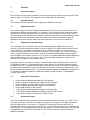
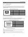
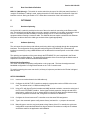
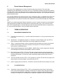
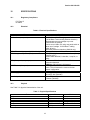
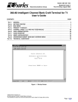
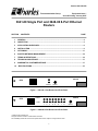
Section 364-180-202
Telecommunication Group
Equipment Issue 1
Second Printing, January 2007
3641-80 Single Port and 3648-80 8-Port Ethernet
Routers
SECTION
CONTENTS
PAGE
1
GENERAL ..................................................................................................................................2
2
INSPECTION..............................................................................................................................5
3
APPLICATION GUIDELINES ....................................................................................................6
4
INSTALLATION .........................................................................................................................9
5
OPTIONING..............................................................................................................................11
6
ROUTER NETWORK MANAGEMENT....................................................................................14
7
TERMS & DEFINITIONS..........................................................................................................14
8
TECHNICAL ASSISTANCE.....................................................................................................17
9
WARRANTY & CUSTOMER SERVICE...................................................................................17
10
SPECIFICATIONS...................................................................................................................19
100 Base-t
3641-80
RTR
RTR MGMT
LINK/Act
RESET
Figure 1. 3641-80 1-Port Router Card Front Panel
LINK/Act
RTR
3648-80
100 B-T
RTR MGMT
1
2
3
4
5
6
7
8
Figure 2. 3648-80 8-Port Router Card Front Panel
©2006 Charles Industries Ltd.
All rights reserved. Printed in United States of America
The availability of features and technical specifications herein subject to change without notice
1
RESET
Section 364-180-202
1
General
1.1
Document Purpose
This document provides general, installation and testing information for the Ethernet Router (RTR) cards
shown in Figure1 and Figure2. This document covers models 3641-80 and 3648-80.
1.2
Document Status
This document reissued to add information regarding the 3648-80 8-port router.
1.3
Equipment Function
The routers are part of the 360-80 Intelligent Channel Bank (ICB). They can function as a router or as a
bridge between the Ethernet port and the T1/E1 transport. They allow point-to-point connection between
two Ethernet IP networks using Point-to-Point Protocol over HDLC (PPPoH) or Frame Relay. The only
differences between the 3641-80 and the 3648-80 is that the 3648-80 has an unmanaged Ethernet switch
designed into the card to eliminate the need of an external hub or switch and does not support E1
applications. Since both units are similar, they will be referred to as ‘the router’ in this document.
1.4
Equipment Location/Mounting
The router plugs into one of the full size slots of the Charles Industries 360-80 ICB shelf and one
controller unit must be installed in the shelf for the unit to operate. The 360-80 routers require an issue 2
or later 3603-81 T1-S Controller with software version v3.1/fpga10 or higher. The 3641-80 one port
router will operate with the issue 1 3603-81 E1-S controller. The Controller GUI or craft terminal can be
used to verify the software for the controller. If the GUI based Network Management System (NMS) is
used, the NMS version must be version v3.5/v5.2 or higher. If the SNMP based Network Node Manager is
used, the MIB must be version 4.4 or higher. See T1 Controller NMS management or craft terminal
practices to for procedure to verify software versions.
If upgrading of the T1-S Controller is required, files are included on the CD shipped with the router unit.
To upgrade the 3603-81 T1-S Controller software, see the 3603-81 T1-S Controller Software Upgrade
Procedure on the CD. To upgrade the NMS version, delete the old software in the ‘Charles’ directory from
the PC and then automatically load the new software from the CD by executing the ‘Setup.exe’ file. The
files are located in CD directory under /T1-S Controller Upgrade Software and MIB/NMS3.5_IADmgmt5.2.
To upgrade the SNMP MIB, delete the old MIB and load the new MIB (filename – CharlesIADmibrv4.4.my) from the CD.
1.5
Reference Documentation
•
•
•
•
•
•
•
•
1.6
Router Guide and Web Browser Manual (LT364-180-N02)
Router Command Line Interface (CLI) Manual (LT364-180-C02)
Router installation and Quick Start-up Guide (LT364-180-802)
Router Troubleshooting Reference Guide (LT-364-180-R02)
Router SNMP Manual (LT364-180-S02)
T1-S Controller Software Upgrade Procedure (LT360-381-U03)
T1-S Controller Network Management Software Guide (LT360-381-S02)
T1-S Controller Craft Port Users Guide (LT360-381-C02)
General Description
The router card provides a point-to-point connection between Ethernet IP networks over a T1/E1. The T1
connection can be set to any rate from 56 Kbps (1 timeslot set to 56 Kbps) to 1.536 Mbps (24 timeslots
set to 64 Kbps) with the T1 controller or to 1.920 Mbs (30 timeslots set to 64 Kbps with the E1-S
controller). With the E1 controller, the unit can use from 1 to 30 timeslots at a rate of 56 or 64 Kbps for the
used timeslots. The assigned timeslots used must be contiguous. The timeslot allocation is done through
a management port on the T1/E1-S Controller unit. See T1/E1-S Controller unit documentation for
additional information.
2
Section 364-180-202
The router functionality can be grouped into 6 different management blocks. Provisioning each of these
blocks creates a wide range of possible applications for the router. Refer to figure 3.
•
•
•
•
•
•
General management of the router.
General LAN functions.
Bridging or routing between the LAN and the WAN.
Creation of virtual private networks (VPNs) between the LAN and remote sites over the WAN.
This feature is typically used for secure transfer of information over the Internet.
The use of a firewall for filtering and translating information from the WAN.
The protocol used by the WAN.
L
A
N
Router
or
Bridge
VPN
Firewall
W
A
N
Management
Figure 3. Ethernet Router Management group Diagram
1.7
Equipment Features
The router provides the following features:
MANAGEMENT/ADMINISTRATION OPTIONS
•
•
•
•
•
•
•
•
•
•
Configurable over Command Line Interface (CLI) RS-232 port
Configurable over a Web Browser via the LAN or T1/E1 port
Configurable using Telnet via the LAN or T1/E1 port
Can be monitored using Simple Network Management Protocol (SNMP)
File Transfer Protocol (FTP) for configuration download/upload
Trivial File Transfer Protocol (TFTP) for system software upgrades
Restores system configuration from nonvolatile memory that was stored or from factory defaults
Bandwidth configurable from 56 Kbps to 1.536 Mbps (1.920 Mbps with E1-S) through timeslot
provisioning on the T1/E1 Controller
Three levels of password security
System Logging protocol (SYSLOG)
IP LAN PROTOCOLS
•
•
•
•
•
•
•
•
•
•
•
Eight Ethernet RJ-45 ports IEEE 802.3 compatible
10/100 BaseT auto sensing
Transmission Control Protocol (TCP)
User Datagram Protocol (UDP)
Passes Point-to-Point Protocol over Ethernet (PPPoE)
Internet Control Message Protocol (ICMP)
Address Resolution Protocol (ARP)
BOOTP supported
Dynamic Host Configuration Protocol (DHCP) server or client
Domain Name Server (DNS) client
Simple Network Time Protocol (SNTP) to allow synchronization to network time
3
Section 364-180-202
IP Bridging and Routing
•
•
•
•
•
•
IP Bridge or Router connectivity over the T1/E1
Static Routing
Classless Inter-Domain Routing (CIDR)
Routing Information Protocol (RIP) V1 and V2
Bridging Control Protocol (BCP)
Internet Group Management Protocol (IGMP) for Web broadcasts
Virtual Private Network Security
•
•
•
•
•
•
Link Control Protocol (LCP)
Layer 2 Tunneling Protocol (L2TP)
Point-to-Point Tunneling Protocol (PPTP)
Generic Routing Encapsulation (GRE) when using L2TP, PPTP or IPSec
Internet Protocol Security (IPSec) with Internet Key Exchange (IKE)
DES, 3DES and Blowfish encryption
FIREWALL
•
•
•
•
•
Port Filtering
Validation
Intrusion Detection
Network Address Translation (NAT)
Network Address Port Translation (NAPT)
Point-to-Point WAN PROTOCOLS
•
•
•
•
1.8
Internet Protocol Control Protocol (IPCP) over HDLC
Password Authentication Protocol (PAP)
Challenge Handshake Authentication Protocol (CHAP)
Frame Relay (bridge or routed)
Management Interfaces
The router operation is provisioned using two separate managers. Timeslot and bandwidth provisioning is
done using the management interfaces for the T1/E1 Controller. Management of the T1/E1 card can be
done through the craft port or the T1 card Ethernet port. The Ethernet port supports both the Network
Management system software (NMS), which is a proprietary GUI based software package, and a Network
Node Manager, which is SNMP based, and requires a SNMP network manager. See the T1/E1 Controller
management documentation for more information.
All other features of the router are controlled using the router management interfaces. One interface is the
Router Management port (RTR MGMT) or Command line Interface, which is accessed through the front
panel DB-9 connector. This interface is an RS-232 interface and uses a standard terminal emulation
program such as HyperTerminal. The interface will accept command scripts to simplify provisioning of
multiple router units. The specific commands available are defined in the Router Command Line
Interface Manual document.
The router features can also be managed over the Router Ethernet LAN port (rear panel access) using a
Web browser or Telnet. The Ethernet is accessed through the rear panel RJ connector. It is 10/100 BaseT auto sensing. Telnet will connect the user to the Command Line Interface. The Web browser will
provide a graphical interface for control of the router. The operation of the Web interface is defined in the
Router Guide / Web Browser Manual document.
4
Section 364-180-202
1.9
Indicators/Switches
The router has 2 indicators per port on the front of the unit.
100 Base-T LED indicates when the Ethernet connection has detected that it is connected to a network
device that supports 100 Base-T. When the indicator is OFF, the Ethernet connection is running at 10
Base-T.
Link/Act LED indicates Ethernet activity detected on the Local Area Network (LAN) Ethernet port.
The router has one switch on the front of the unit.
RESET switch located on the front of the unit will force a ‘soft’ reset. This will restore the router
configuration to the last ‘saved’ configuration.
The 3641-80 has one switch on the rear of the unit.
HUB/PC switch is located on the rear of the 3641-80 unit. In the HUB position the Ethernet connection
should be connected to an Ethernet hub or switch. In the PC position the Ethernet connection should be
connected directly to a PC.
The 3648-80 has no switches on the rear of the unit.
2
INSPECTION
2.1
Inspection for Damages
Inspect the equipment thoroughly upon delivery. If the equipment has been damaged in transit,
immediately report the extent of damage to the transportation company.
2.2
Equipment Identification
Charles Industries’ equipment is identified by a model and issue number imprinted on the front panel or
located elsewhere on the equipment. Each time a major engineering design change is made on the
equipment, the issue number is advanced by 1 and imprinted on subsequent units manufactured.
Therefore, be sure to include both the model number and its issue number when making inquires about
the equipment.
2.3
Static Concerns
Each unit is shipped in static-protective packaging to prevent damages from electrostatic charges. Use
approved static-preventive measure, such as static-conductive wrist straps and a static-dissipative mat,
when handling units outside of their protective packaging. A unit intended for future use should be tested
as soon as possible and returned to its original protective packaging for storage.
This equipment contains static-sensitive electronic devices. To prevent electrostatic charges from
damaging static-sensitive units:
• Use approved static-preventive measures (such as static-conductive wrist straps and staticdissipative mats) at all times whenever touching units outside of their original, shipped, protective
packaging.
• Do not ship or store units near strong electrostatic, electromagnetic, or magnetic fields.
• Always use the original static-protective packaging for shipping or storage. Return a tested unit to
its original protective packaging for storage.
5
Section 364-180-202
3
APPLICATION GUIDELINES
Provisioning each of the feature sets creates a wide range of possible applications for the router. This
section will show the most common use of these features but not the only combinations that could be
used.
A form is included to assist in determining the provisioning of the system. See optioning section for form.
3.1
LAN General Features
The router card provides support for IP through TCP, UDP, ICMP, BOOTP and ARP. For address and
domain resolution the router supports DHCP (client, relay or server) and DNS (client and relay).
Administrators can use both FTP and TFTP for code and configuration updates. To maintain a log of
router activity SYSLOG is supported. The ability to handle broadcasts over the network is supported by
IGMP. SNTP will allow the system to set its time to a network device.
The router will work in either bridge or routed modes in both client-client or client-server end-to-end
configurations. When used in conjunction with non-Charles routers, the router should be used in the client
configuration.
3.2
Private Network Bridge Extension
To extend a private network to a new location you can do this using the bridge or router feature. Figure 4
illustrates a typical private network application. The unit can be provisioned to provide routing or bridging
over the T1/E1 to the remote network. If the router is provisioned for bridge mode, all IP traffic from the
Ethernet interface will be sent to the remote router and output to the remote network.
360-80
LAN
Ethernet
T1/E1
R
O
U
T
E
R
360-80
R
O
U
T
E
R
LAN
Ethernet
Figure 4. Point-to-Point Private Network Application
The advantage of using a bridge is that it requires less provisioning and bridges the same LAN subnet. In
this application the LAN Bridge and the WAN protocol feature sets are the only ones that need to be
configured. In this application the router is transparent to all IP traffic. The LAN general feature set can be
provisioned as desired. An IP address can be provisioned if Ethernet management is desired. The WAN
interface is normally configured for PPPoH with no authentication since the network is private. For more
detailed information on the provisioning of the router, see the Quick Start-up reference guide and script
library.
3.3
Private Network Router Extension
For private networks that want to reduce the amount of data over the WAN interface to only the data that
is going from the local LAN to the remote LAN should configure the router as a router. In this application
the router feature set and the WAN protocol need to be provisioned. In this application the router will
6
Section 364-180-202
check data on the LAN and determine if it is to be routed to the remote LAN. This requires the configuring
of routing information protocol (RIP) tables unless static routing tables are used. The LAN general feature
set can be provisioned as desired. An IP address is required for both the LAN side interface and the WAN
side interface. The WAN interface is normally configured for PPPoH with no authentication since the
network is private. For more detailed information on the provisioning of the router, see the Quick Start-up
reference guide and script library.
3.4
Firewall Protection from Internet Service Provider
For applications that will feed directly into the Internet (through a service provider) the router can provide
firewall protection. This is done through filtering, translation and intrusion detection. The router can
translate IP addresses (NAT) and ports (NAPT) to reduce visibility of the LAN and therefore protect the
LAN. The router is normally configured as a router to eliminate transmission of local LAN traffic to the
WAN. The LAN general feature set can be provisioned as desired. An IP address is required for both the
LAN side interface and the WAN side interface. The WAN interface is normally configured for PPPoH with
no authentication to the service provider. If authentication for the PPPoH link is needed, the router
through ICMP using PAP or CHAP provides it. Another option for the WAN is frame relay. The WAN
frame relay interface can be configured for either frame relay bridge or frame relay routed. This would
depend on the type of frame relay service provided by the service provider. For more detailed information
on the provisioning of the router, see the Quick Start-up reference guide and script library.
3.5
Virtual Private Network through an Internet Service Provider
For applications that require virtual private networks (VPNs) through the Internet, connection to the
Internet is shown in figure 5. In this application the T1/E1 timeslots containing the data from the router are
sent to an Internet Service Provider (ISP) and interfaced to the Internet.
360-80
LAN
Ethernet
T1/E1
R
O
U
T
E
R
Internet
Figure 5. Broadband Connection to an ISP Application
The router provides multiple tunneling protocols (PPTP, L2TP) and the ability to encrypt the data using
GRE. Encryption is done using the IP Security feature of the router. With this feature the router provides
certification, keys (IKE) and different methods of encryption to ensure security across the public network.
The VPN feature is normally used in conjunction with the firewall feature to protect the LAN. The router is
normally configured as a router to eliminate transmission of local LAN traffic to the WAN. The LAN
general feature set can be provisioned as desired. An IP address is required for both the LAN side
interface and the WAN side interface. The WAN interface is normally configured for PPPoH with no
authentication to the service provider. If authentication for the PPPoH link is needed, the router through
ICMP using PAP or CHAP provides it. Another option for the WAN is frame relay. The WAN frame relay
interface can be configured for either frame relay bridge or frame relay routed. This would depend on the
type of frame relay service provided by the service provider. For more detailed information on the
provisioning of the router, see the Quick Start-up reference guide and script library.
7
Section 364-180-202
3.6
Drop and Insert Area Network Extension
For applications that require connection of multiple LANs, utilization of the 360-80 and its Drop and Insert
capability can be used to connect the networks and allow traffic between them. See Figure 6 for an
example of this equipment configuration. This configuration is similar to the private point-to-point
application. In this application two routers are required at each ‘drop and insert’ location.
LAN
Ethernet
LAN A
ROUTER
360-80
Ethernet
T1
LAN
ROUTER
Ethernet
LAN B
360-80
ROUTER
Ethernet
T1
Ethernet
LAN C
LAN
ROUTER
Ethernet
360-80
Figure 6. Broadband Connection using Drop and Insert
8
Section 364-180-202
4
INSTALLATION
4.1
Attaching the Rear Panel
The rear panel of the unit should be installed before the unit is installed in the shelf and before wiring
begins.
LAN
HUB
PC
Figure 7. 3641-80 1-Port Ethernet Router Rear Panel
LAN 8
LAN 1
Figure 8. 3648-80 8-Port Ethernet Router Rear Panel
4.2
Installing the Unit
The router card installs in a full size slot of the 360-80.
4.2.1
Step
1.
2.
3.
4.
5.
6.
4.2.2
Installing a New Unit
Action
If not already installed, install the rear panel, screwing it to the appropriate mounting location on
the shelf using the provided hardware
Insert the unit into the shelf, making sure that the unit is aligned with the card guides inside the
shelf.
CAUTION
If there is already a rear panel installed on the shelf, check for interference. The rear may need
to be removed and replaced with the rear panel shipped with the new unit.
Slide the unit fully into the shelf. Use the insertion lever to fully seat the unit.
Once the unit is fully inserted, tighten the securing screw on the front panel of the unit.
Connect the Ethernet cable at the rear of the unit. If the RTR is connected to a hub, insure that
the HUP-PC switch is positioned toward HUB
After the RTR has completed it’s self test and powered up, check the RTR IP address and
software provisioning through the front panel RTR MGMT interface.
Installing a Replacement Unit
If you are replacing a unit that is already in service, insure that the new unit is the same as the unit being
replaced.
Step
1.
2.
3.
4.
Action
Upload the provisioning for the router through the management (CLI) interface using ‘ftp’. See
section 8.2 of Router Guide and Web Browser Manual
Remove the wiring connectors from the front and rear of the unit.
Unscrew the front panel securing screw to release the unit from the shelf.
Using the card ejector, remove the unit from the shelf.
9
Section 364-180-202
5.
Follow the procedure for installing a new unit.
4.3
4.3.1
Connector Definitions
Ethernet Interface Wiring
Table 1 shows the standard interface pinouts for the RJ45 rear panel connector on the 3641-80 and pin
designations for the Ethernet interface. This interface is used to connect to the local Ethernet LAN. The
3648-80 has auto crossover detection and will automatically switch the pinouts based on the detection of
signal on the connector.
TABLE 1. 3641-80 RJ45 Jack Pinouts
1 2 3 4 5 6 7 8
4.3.2
Pin #
1
2
3
4
5
6
7
8
Use (PC selected)
XMT (TD+)
XMT (TD-)
RCV (RD+)
NC
NC
RCV (RD-)
NC
NC
Use (HUB selected)
RCV (RD+)
RCV (RD-)
XMT (TD+)
NC
NC
XMT (TD-)
NC
NC
Router Management Interface Wiring
Table 2 show the standard interface pinouts for the female 9 pin front panel connector and pin
designations for the Console interface. The interface is designed as the DCE side to allow a straight DB-9
male to DB-9 female cable to be used between a PC and the router console interface port.
Table 2. Router Management Jack Pinouts
Pin 1
Pin 6
4.4
Pin #
1
2
3
4
5
6
7
8
9
Use
-Received Data – router output
Transmitted Data – router input
Data Terminal Ready – router input
Signal Ground
Data Set Ready – router output
----
Front Panel Switch and LED Definitions
RESET – Pressing this button will initiate a ‘soft’ reset of the router. The router configuration will be the
last ‘saved’ configuration after reset is complete.
100 Base-t – This LED will turn ON when 100 Base-T activity is detected on the LAN interface.
LINK/Act – This LED will turn ON when connected and blink when packets are detected on the LAN
interface.
10
Section 364-180-202
4.5
Rear Panel Switch Definition
HUB PC (3641-80 only) – This switch is used to switch the pinouts of the LAN (rear panel) interface. If
‘straight’ 10/100 Base-T cabling is used, setting the switch to ‘HUB’ allows direct connection of the LAN
interface to a hub. Setting the switch to ‘PC” allows direct connection of the LAN interface to a PC.
5
OPTIONING
5.1
Hardware Optioning
On the 3641-80, a switch is provided on the rear of the unit to assist in connecting to the Ethernet LAN
port. The switch will provide the ability to provide a ‘straight’ connection for use when connecting to a hub
or a PC. The switch provides the ability to connect directly to a PC or other terminating piece of
equipment without creating a crossover cable. The 3648-80 does not require a switch since its Ethernet
LAN ports are able to detect the cable type and switch the signals appropriately.
5.2
Software Optioning
The unit comes from the factory with default provisioning which can be altered through the management
interfaces. The configuration can be changed locally through the RTR MGMT CLI (Command Line
Interface) or remotely by using a WEB Browser such as Microsoft’s Internet Explorer on the LAN or WAN
network.
The optioning and operation of the router through the RTR MGMT CLI port is explained in the Router
Command Line Interface Manual. The optioning and operation of the router through the Web browser is
explained in the Router Guide and Web Browser Manual.
Default Unit Configurations
The router card stores its operating configuration on the router card. The time slot assignment and
bandwidth configuration is configured and stored on the T1/E1 Controller card.
To assist in optioning the router over the CLI, a library of scripts are provided on the CD that is shipped
with the router.
SETUP PROCEDURE
5.2.1
Insert router card and attach the LAN cable only.
5.2.2
Configure the 360-80 T1/E1 Controller to assign the appropriate number of DS0s to the router
card. The default value is 12 DS0s at 64kb per DS0.
5.2.3
Using a PC, with HyperTerminal emulator and ANSI terminal emulation, connect the serial port of
the PC to the RTR MGMT interface. Under HyperTerminal properties, settings tab and ASCII
setup button, configure a 10 ms or greater delay for both the line delay and the character delay.
Under the properties connection tab, configure the connection for 9600 8-N-1.
5.2.4
Configure the far end router and T1 controller to use the same DS0 assignment.
5.2.5
Type in the command ‘system config restore factory’ and wait for --> prompt to be returned.
5.2.6
Manually type or use the ‘copy’ and ‘paste to host’ feature of the PC to transfer the quick start
configuration commands listed below into HyperTerminal. Remember to modify the IP address
and subnet mask for the application and installation.
11
5.2.7
5.2.8
Section 364-180-202
Make sure there is a carriage return entered after the “system config save” command and the
message “wait for ‘configuration saved’ message...” is displayed. This takes about 15 seconds.
Restart the router by pushing the front panel RESET button or enter “system restart” at the
Æ prompt to activate the new configuration. It can take up to 6 minutes for the router link to be
established and traffic to start to be exchanged.
NOTE: The router must be RESET after any change in the card rate over the T1 (using a T1/E1
Controller management interface). The router must also be RESET after any change in router
configuration. The configuration must be SAVED before the unit it RESET.
See section 8.4 (CLI Applications) of the Router Guide and Web Browser Manual for other detailed
application examples.
The CD shipped with the router contains a library of command scripts examples; PPP bridge client v1.0,
PPP routed client v1.0, PPP routed Cisco v1.0, PPP bridge Cisco v1.0.
EXAMPLE CONFIGURATION FOR PPP
In this example the LAN address is 192.168.0.1 with a subnet of 255.255.255.0 and the WAN address is
10.10.10.1 with a subnet of 255.255.255.0. Be sure to change IP address as needed to insure each
router address is unique.
Type in or ‘copy’ and ‘paste to host’ the following commands into HyperTerminal:
ip clear interfaces
ip clear routes
transports clear
port fr set AutoStart false
port fb set AutoStart false
dhcpclient update
ethernet add transport eth1 ethernet
ip add interface ip1 192.168.0.1 255.255.255.0
ip attach ip1 eth1
pppoh add transport ppp1 dialout 1 hdlc
pppoh set transport ppp1 welogin none
pppoh set transport ppp1 subnet 255.255.255.0
ip add interface ip2
ip attach ip2 ppp1
system config save
12
Section 364-180-202
5.3
Router Configuration Worksheet
To assist in keeping track of the configuration of the router, a worksheet has been provided.
Router A
LAN
IP:
Mask:
“ethernet”
port
LAN “IP”
WAN “IP”
Name:
Name:
Addr:
Addr:
Transport
other LAN devices
Transport
Name:
Name:
Device:
Addr:
Options
Device:
Addr:
“Bridge” “IP”
(for mgmt when using bridge)
Addr:
WAN “Bridge”
Dial-in/out (hdlc):
Username (hdlc)
Name:
Name:
Password (hdlc)
Addr:
Addr:
VPN
TP:
IKE:
NAP:
NAPT:
LAN “Bridge”
Device:
Addr:
DHCP:
DNS:
SNTP:
Device:
Addr:
Options
DLCI (fr):
Encap (fr):
Name:
SNMP
Community Name:
“fr” port
(frame relay)
or
“hdlc” port
(PPPoH)
Router B
LAN
IP:
Mask:
“ethernet”
port
LAN “IP”
WAN “IP”
Name:
Name:
Addr:
Addr:
Transport
other LAN devices
Transport
Name:
Name:
Device:
Addr:
Options
Device:
Addr:
Device:
Addr:
Device:
Addr:
“Bridge” “IP”
(for mgmt when using bridge)
Addr:
WAN “Bridge”
Dial-in/out (hdlc):
Username (hdlc)
Name:
Name:
Password (hdlc)
Addr:
Addr:
VPN
TP:
IKE:
NAP:
NAPT:
LAN “Bridge”
DHCP:
DNS:
SNTP:
Options
DLCI (fr):
Encap (fr):
Name:
SNMP
Community Name:
“fr” port
(frame relay)
or
“hdlc” port
(PPPoH)
13
Section 364-180-202
6
Router Network Management
The router can be managed over a variety of interfaces using many protocols. The router has a
management port (RTR MGMT) on the front of the unit. This interface provides a command line interface
(CLI) that can be used to provision and monitor the status of the local router. This interface must be used
to provision the router for communication over the LAN and WAN interfaces. The CLI provides 3 levels of
password authentication
The LAN and WAN Ethernet interfaces support many management options. A standard web browser (like
Internet Explorer) can be used to connect to the router to view and modify provisioning. Telnet can be
used and provides a command line interface that is identical to the CLI provided through the craft/console
port.
SNMP can be used through either Ethernet interfaces to provide a means to monitor the router operation
and read provisioning. SNMP also supports traps to indicate the status of the T1/E1 connection of the
shelf. The CD shipped with the router provides a manual that shows what MIB objects are supported by
the router and also the MIBs for use by an SNMP browser application.
7
TERMS & DEFINITIONS
7.1
MANAGEMENT/ADMINISTRATION
7.1.1
Command Line Interface (CLI) – An ASCII based serial interface. It can only communicate to the
local router.
7.1.2
Web Browser – an application program (i.e. Netscape or Internet Explorer) that uses HTTP to
make requests on behalf of the browser user using a graphical user interface.
7.1.3
Telnet – a protocol that allows a remote computer terminal the ability to access a local computer
interface and look like it is part of the computer’s local system. On a PC this command is
executed from the MSDOS prompt.
7.1.4
Simple Network Management Protocol (SNMP) – SNMP utilizes a node manager with a browser
and a Management Information Base (MIB) to monitor unit status.
7.1.5
File Transfer Protocol (FTP) – FTP uses TCP and is a simple protocol used to exchange files
between computers. It requires clients to authorize themselves with a login and password before
requesting file transfers. It is commonly used to download programs and files from servers to
computers.
7.1.6
Trivial File Transfer Protocol (TFTP) - TFTP is simpler to use than FTP but does not support user
authentication or directory visibility. It uses UDP and not TCP.
7.1.7
System Logging protocol (SYSLOG) – SYSLOG is a feature that will send a message to a log file.
7.2
7.2.1
IP LAN PROTOCOLS
Transmission Control Protocol (TCP) - TCP is a communication protocol that is used to keep
track of the individual packets a message is divided into for efficient routing through the Internet.
It is connection-oriented which means that a connection is established and maintained until the
message or messages to be exchanged by the application programs have been exchanged.
14
7.2.2
Section 364-180-202
User Datagram Protocol (UDP) - UDP is a message protocol (different from TCP) that does not
provide sequencing of packets. Therefore the application program must be able to make sure that
the entire message has arrived and in the right order. It does provide port numbers to distinguish
different user requests and optionally a checksum to verify data arrived intact.
7.2.3
Point-to-Point Protocol over Ethernet (PPPoE) provides a way for multiple different users to share
the same physical connection to a remote service provider.
7.2.4
Internet Control Message Protocol (ICMP) – ICMP is a communication protocol that is used for
error reporting and message control between hosts and routers. It uses IP datagrams that are
processed at the IP software level. This is the basis for ping (Protocol INternet Gopher)
7.2.5
Address Resolution Protocol (ARP) - ARP is a protocol for mapping IP addresses to a physical
machine address (Media Access Control, MAC). A table, usually called the ARP cache, is used to
maintain a correlation between the MAC and the corresponding IP address.
7.2.6
DHCP Relay uses the BOOTP (BOOTstrap Protocol) relay agent behavior to eliminate the need
of having a DHCP server on each physical network segment.
7.2.7
Dynamic Host Configuration Protocol (DHCP) lets network administrators centrally manage and
automate the assignment of IP addresses in a network. It uses the concept of a ‘lease’ or the
amount of time that a given IP address will be valid for a computer. The lease time can vary
depending on how long the user will require the Internet connection. It also supports static
addresses for computers needing a permanent IP address. DHCP Server is the host that
provides the parameters. DHCP Client is the host requesting parameters
7.2.8
Domain Name Server (DNS) client uses a Domain Name server to locate and translate Internet
domain names into IP addresses.
7.2.9
Simple Network Time Protocol (SNTP) is used to allow equipment on a network to synchronize to
network time using a SNTP server.
7.3
IP Bridging and Routing
7.3.1
Static Routing is the ability to input directly into the routing table of a router. When a route is
statically entered into the table, it usually takes precedence over the dynamic route information
7.3.2
Classless Inter-Domain Routing (CIDR) is the ability to mask on an individual bit basis. Originally
Class A, B or C allowed the mask to be set on an octet level instead of a bit level. Classless
routing provides for bit level LAN subnetting. This provides the ability to further segregate the
LANs into smaller LANs to minimize LAN traffic.
7.3.3
Routing Information Protocol (RIP) V1 and V2 – RIP is used to manage router information within
a local/corporate LAN. The gateway host sends its entire router table to its closest neighbor host
every 30 seconds. This continues until all hosts have the same knowledge of routing paths
(referred to as network convergence). RIP uses hop count to determine network distance.
7.3.4
Bridging Control Protocol (BCP) is responsible for configuring, enabling and disabling the bridging
protocol features on both ends of a point-to-point connection.
7.3.5
Internet Group Management Protocol (IGMP) – IGMP is a protocol that provides a way for a
computer to report its multicast group membership to adjacent routers. Multicast allows a
computer to send content to multiple other computers that have identified themselves as
interested in the originating computer’s content.
15
Section 364-180-202
7.4
Virtual Private Network Security
7.4.1
Link Control Protocol (LCP) is used in point-to-point protocols to establish, configure and test the
data link Internet connection.
7.4.2
Layer 2 Tunneling Protocol (L2TP) is an extension of PPTP and provides a means of
encapsulation to transmit multi-protocol packets over layer 2 point-to-point links.
7.4.3
Point-to-Point Tunneling Protocol (PPTP) is used to extend a corporate network through a private
tunnel over the public network.
7.4.4
Generic Routing Encapsulation (GRE) allows any network protocol to be transmitted over a
network running a different protocol by encapsulating the packets of the network protocol within
GRE packets.
7.4.5
Internet Protocol Security (IPSec) with Internet Key Exchange (IKE) is a set of protocols for
security at the network or packet-processing layer. It is useful for virtual private networks and
remote user access.
7.4.6
Data Encryption Standard (DES), 3DES and Blowfish are encryption algorithms for a more secure
exchange using IPSec.
7.5
FIREWALL
7.5.1
Port Filtering is a series of rules that determine how a packet should be handled. The routes
define the protocol type, the range of source and destination ports numbers and an indication of
whether or not the packet should be allowed. When a packet arrives the filter list is searched for a
match that will indicate if the packet. Filters may overlap as the search finds the most specific
rule.
7.5.2
Validation is similar to port filters. They are rules to define handling of packet based on source or
destination IP address. The validation allows ranges of IP addresses to be specified and the
action to be taken on packets from or to addresses in that range. This is a powerful mechanism
that allows users to block packets from certain addresses while allowing others.
7.5.3
Intrusion Detection provides a means to identify possible security attacks. Some attacks will
cause a host to be blacklist (i.e., no traffic from that host is accepted under any circumstances)
for a period of the time. Other attacks are simply logged.
7.5.4
Network Address Translation (NAT) is the translation of an IP address used within one network to
a different IP address used within another network.
7.5.5
Network Address Port Translation (NAPT) is more correctly called PAT. PAT will store addresses
and the translated port tables for each active clients and assigns new port numbers to new clients
that are on the network. It defines the number of port reassignments assigned to each active IP
client. It provides a similar functionality to NAT, but is a more specific tool. PAT forwards requests
for a particular IP and port pair to another IP port pair. This feature is commonly used on publicly
connected hosts to make an internal service available to a larger network.
7.6
7.6.1
Point-to-Point WAN PROTOCOLS
Internet Protocol Control Protocol (IPCP) is responsible for configuring, enabling and disabling
the IP protocol features on both ends of a point-to-point connection.
16
7.6.2
Section 364-180-202
Password Authentication Protocol (PAP) connects one computer to another and sends a plain
text login and password.
7.6.3
Challenge Handshake Authentication Protocol (CHAP) uses a 3-way type handshake process
that uses a dial back routine and encrypted password. In addition the server sends a randomly
generated challenge string to the client, along with its hostname. The client uses the hostname to
look up an appropriate key, combines this with the challenge and encrypts it with a one-way
hashing mechanism. The resulting string is returned to the server, along with the client’s
hostname. The server performs the same computation, as the client, on the challenge string. The
server will only allow the client to connect if its computation result is identical to that received from
the client.
7.6.4
Frame Relay (bridge or routed) is a service that provides cost-efficient data transmission for
intermittent traffic between local area networks or between endpoints in a wide area network. It is
based on packet-switched technology where the protocol does not correct errors but depends on
the end points to detect and request retransmission of bad packets.
8
TECHNICAL ASSISTANCE
If technical assistance is required, contact Charles Industries’ Technical Services Center at
847-806-8500
847-806-8556 (FAX)
800-607-8500
[email protected] (e-mail)
9
WARRANTY & CUSTOMER SERVICE
9.1
Warranty
Charles Industries, Ltd. offers a 2-year warranty on this product. Contact your local Sales Representative
at the address or telephone numbers below for warranty details. The warranty provisions are subject to
change without notice. The terms and conditions applicable to any specific sale of product shall be
defined in the resulting sales contract.
Charles Industries, Ltd.
5600 Apollo Drive
Rolling Meadows, Illinois 60008-4049
847-806-6300 (Main Office)
847-806-6231 (FAX)
9.2
Field Repairs (In-Warranty Units)
Field repairs involving the replacement of components within a unit are not recommended and may void
the warranty and compatibility with any applicable regulatory or agency requirements. If a unit needs
repair, contact Charles Industries, Ltd. for replacement or repair instructions, or follow the Repair Service
Procedure below.
9.3
Advanced Replacement Service (In-Warranty Units)
Charles Industries Ltd. offers an “advanced replacement” service if a replacement unit is required as soon
as possible. With this service, the unit will be shipped in the fastest manner consistent with the urgency of
the situation. In most cases, there are no charges for in-warranty repairs, except for the transportation
17
Section 364-180-202
charges of the unit and for a testing and handling charge for units returned with no trouble found. Upon
receipt of the advanced replacement unit, return of out-of-service unit in the carton in which the
replacement was shipped, using the pre-addressed shipping label provided. Call your customer service
representative at the telephone number above for more details.
9.4
Standard Repair and Replacement Service (Both In-Warranty and Out-Of-Warranty
Units)
Charles Industries, Ltd. offers a standard repair or exchange service for units either in- or out-of-warranty.
With this service, units may be shipped to Charles Industries for either repair and quality testing or
exchanged for a replacement unit, as determined by Charles Industries. Follow the Repair Service
Procedure below to return units and to secure a repair or replacement. A handling charge applies for
equipment returned with no trouble found. To obtain more details of this service and a schedule of prices,
contact the Charles Service Center at 217-32-5288 (FAX 217-932-2943).
Repair Service Procedure
1. Prepare, complete, and enclose a purchase order in the box with the equipment to be returned.
2. Include the following information:
- Company name and address
- Contact name and phone number
- Inventory of equipment being shipped
- Particulars as to the nature of the failure
- Return shipping address
3. Ship the equipment, purchase order, and above-listed information, transportation prepaid, to
the service center address shown below.
Charles Service Center
503 N.E. 15th Street
P.O. Box 339
Casey, IL 62420-2054
4. Most repaired or replaced units will be returned within 30 to 45 days, depending on the product
type and availability of repair parts. Repaired units are warranted for either 90 days from the date
of repair or for the remaining unexpired portion of the original warranty, whichever is longer.
18
Section 364-180-202
10
SPECIFICATIONS
10.1
Regulatory Compliance
FCC Part 15
UL60950
10.2
Electrical
Table 6. Electrical Specifications
Parameter
Transmission Rate
LAN interface (rear panel)
HUB – PC switch (rear panel) (3641-80 only)
RTR Management (On front panel)
LEDs (front panel, one per port)
RESET switch (front panel)
Power supply input voltage range
Power supply current
Heat dissipation
10.3
Specification
56 Kbps to 1.536 Mbps
RJ45 LAN and Web Management Interface:
(10/100 Base-T auto-sensing Ethernet interface)
Web management can manage any router
connected to the network.
Can be set to HUB or PC using rear panel switch to
allow use of ‘straight’ 10/100 Base-T cabling.
(3641-80 only)
Auto cable crossover detection (3648-80 only)
See specification on LAN interface
DB-9 (RS-232) Command Line Interface: (directly
connects to PC)
Default: data rate 9600, 8 data bits, 1 stop bit, no
parity
100 Base-t: ON indicates 100 Base-T LAN
connection detected.
LINK/Act: ON indicates LAN detected
Pressing switch will cause a ‘soft’ reset of the
router. This will restorer the router to the last
‘saved’ configuration.
-42V to –56V
50 mA @ -48V (3641-80)
80 mA @ -48V (3648-80)
2.4 watts (3641-80)
3.9 watts (3648-80)
Physical
See Table 7 for physical characteristics of the unit.
Table 7. Physical Specifications
Feature
U.S.
Metric
0.75 inch
1.9 centimeters
9.625 inches
24.45 centimeters
9.25 inches
23.49 centimeters
11.3 ounces
320 grams
-40° F to +149° F
-40° C to +65° C
<95% (non-condensing)
Height
Width
Depth
Weight
Temperature
Humidity
19