1
ADSL
Bridge/Routers
AT-AR240E
AT-AR250E
K
User’s
Guide
PN 613-50197-00 Rev A
®
Copyright 2001 Allied Telesyn International, Corp.
960 Stewart Drive Suite B, Sunnyvale, CA 94085 USA
All rights reserved. No part of this publication may be reproduced without prior written permission from
Allied Telesyn International, Corp.
All other product names, company names, logos or other designations mentioned herein are trademarks
or registered trademarks of their respective owners.
Allied Telesyn International, Corp. reserves the right to make changes in specifications and other
information contained in this document without prior written notice. The information provided herein is
subject to change without notice. In no event shall Allied Telesyn International, Corp. be liable for any
incidental, special, indirect, or consequential damages whatsoever, including but not limited to lost
profits, arising out of or related to this manual or the information contained herein, even if Allied
Telesyn International, Corp. has been advised of, known, or should have known, the possibility of such
damages.
FCC Notice
FCC NOTICE
According to Federal Communications Commission (FCC) Rules
regarding radio frequency emissions, the ADSL device complies
with FCC Part 15 for Class B computing devices. The following
paragraph is required by the FCC.
This equipment generates, uses and can radiate radio frequency
energy and if not installed and used in accordance with this
document, may cause interference to radio communications. It
has been tested and found to comply with the limits for a Class B
computing device pursuant to Part 15 of FCC Rules. These limits
are designed to provide reasonable protection against such
interference when the equipment is operated in a commercial
environment. Operation of this equipment in a residential area is
likely to cause interference, in which case, the user, at his own
expense, is required to take whatever measures may be necessary
to correct the interference. If this equipment does cause harmful
interference to radio or television reception, the user is
encouraged to try to correct the interference by one or more of the
following measures:
•
Turn the equipment “OFF” and “ON”.
•
Reorient or relocate the receiving antenna.
•
Increase the distance between the equipment and the receiver.
•
Connect the equipment to an outlet on a circuit different from
that to which the receiver is connected.
iii
FCC Notice
NOTE
Any changes or modifications not
expressly approved by the grantee of
this device could void the user’s
authority to operate the equipment.
Meets Canadian D.O.C.
This product conforms with Canadian Class B Emissions
Regulations.
Meets Approvals
Safety
: FCC Part 68, EN60950, UL 1950, C/UL to CSA 22.2
No.950, TUV, IC CS03
Emissions : FCC Part 15 Class B, EN55022 / CISPR2 Class B
Immunity : EN55024
Warning
Use minimum of 26 AWG line cord for the DSL
connection.
iv
Table of Contents
TABLE OF CONTENTS
FCC Notice ........................................................................................iii
Introduction ....................................................................................viii
Package Contents ............................................................................... ix
Minimum PC Requirements ............................................................... ix
Chapter 1
Product Description .......................................................................... 1
1.1 Introduction .................................................................................. 1
1.2 Product Description ...................................................................... 2
1.3 Front Status Indicators .................................................................. 3
1.4 AT-AR240E Rear Panel ............................................................... 4
1.5 AT-AR250E Rear Panel ............................................................... 5
1.6 System Inter-operability ............................................................... 6
1.7 System Interface (LAN) ............................................................... 7
1.8 System Interface (DSL) ................................................................ 8
1.9 Installation and Configuration ...................................................... 8
Chapter 2
Operation ........................................................................................... 9
2.1 Introduction .................................................................................. 9
2.2 System Description ..................................................................... 10
2.3 Routing ....................................................................................... 10
2.4 Network Address Translation ..................................................... 11
2.5 Static Routing ............................................................................. 12
2.6 Bridging ...................................................................................... 12
2.7 Point-to-Point Protocol ............................................................... 13
2.8 Security ....................................................................................... 14
2.9 PC Setup for Telnet .................................................................... 15
v
Table of Contents
2.10
2.11
2.12
2.13
2.14
USB Port Setup ........................................................................ 16
ADSL Transmission ................................................................. 17
ATM Transmission ................................................................... 17
BOOTP Download Procedure .................................................. 18
Updating Firmware via TFTP .................................................. 22
Chapter 3
Applications ..................................................................................... 25
3.1 Introduction ................................................................................ 25
3.2 High-Speed Internet Access ....................................................... 26
3.3 Remote Locations Connectivity ................................................. 27
3.4 LAN-to-LAN Connectivity ........................................................ 28
Chapter 4
Advanced Configuration ................................................................. 29
4.1 Introduction ................................................................................ 29
4.2 Accessing the Advanced Configuration Mode ........................... 30
4.3 Main Statistics Screen ................................................................ 31
4.4 File Drop-down Menu ................................................................ 32
4.5 Configuration Drop-down Menu ................................................ 33
4.5.1 Configuration Menu - Advanced Configuration .............. 34
4.5.2 Configuration Menu - Security ........................................ 35
4.6 Operation Drop-down Menu ...................................................... 37
4.6.1 Operation Menu - View Performance .............................. 37
4.7 Help Menu .................................................................................. 38
Chapter 5
Command Line Interface Commands ........................................... 39
5.1 Introduction ................................................................................ 39
5.2 Changing the Password .............................................................. 40
5.3 Update Flash Memory ................................................................ 40
5.4 System Console Commands ....................................................... 41
5.4.1 Bridge Commands .......................................................... 41
5.4.2 DHCP Client Commands ................................................. 44
vi
Table of Contents
5.4.3 DHCP Server Commands ................................................ 46
5.4.4 NAT Commands .............................................................. 48
5.4.5 PPP Commands ................................................................ 52
5.4.6 RFC1483 Commands ....................................................... 59
5.4.7 TCP/IP Commands .......................................................... 59
5.4.8 TFTP Commands ............................................................. 70
5.5 ADSL Commands ...................................................................... 71
5.5.1 Help .................................................................................. 71
5.5.2 Info ................................................................................... 72
5.5.3 Setting .............................................................................. 72
5.5.4 Activate ............................................................................ 75
5.5.5 Loopback ......................................................................... 76
5.5.6 Status ................................................................................ 77
5.5.7 ATM ................................................................................. 79
5.5.8 Performance ..................................................................... 80
5.5.9 Debug ............................................................................... 81
5.5.10 HTUType ....................................................................... 84
5.6 Advanced CLI Commands ......................................................... 84
5.6.1 Bridge Settings ................................................................. 84
Appendix A
Troubleshooting Guide ................................................................... 97
Appendix B
Specifications of AT-AR240E ....................................................... 107
Appendix C
Specifications of AT-AR250E ....................................................... 111
Appendix D
Interface Pin Assignments ............................................................ 115
Appendix E
Default Settings .............................................................................. 116
vii
Introduction
Introduction
The Broadband Intelligent Home Gateway (BIHG) is an emerging
new class of CPE device that grows with the home network without
requiring Service Providers to change their DSL provisioning.
Regardless if the connection is through the USB or the Ethernet
port, you are always on. For network expansion, a hub can be connected to the Ethernet port.
The AT-AR240E and the AT-AR250E capabilities save money
during deployment by provisioning longer reach with more reliable
turn up, less truck rolls and more customer satisfaction by using the
BIHG feature. Both the AT-AR240E and the AT-AR250E’s
flexibility enables it to be set as a router to accommodate more
advanced business applications.
With the ADSL device, investments are protected through the
support of popular DSL connection models which are also industrystandard interface options such as PPP over Ethernet (PPPoE) and
PPP over ATM (PPPoA), Bridging and Routing.
viii
Introduction
Package Contents
1.
2.
3.
4.
5.
6.
7.
AT-AR240E OR AT-AR250E ADSL Bridge/Router
DSL Cable (RJ-11, green cable)
Ethernet Cable (RJ-45, yellow cable)
USB Cable (grey cable)
Power Cord (not included with the AT-AR250E)
Power Adapter
CD with the GUI, USB Drivers and Documentation
Minimum PC Requirements
=
=
=
=
ix
A PC with an installed 10BaseT Ethernet card or USB interface.
TCP/IP network protocol installed on the PC.
Windows 95 (USB port may have some compatibility issues),
Windows 98, Windows 2000, Windows NT 4.0 (no support for
USB) or Windows Me.
For Ethernet connectivity to the ADSL devices, any Operating
System with the TCP/IP protocol such as Linux, Mac, OS2 may
be used.
Chapter 1
CHAPTER
1
PRODUCT DESCRIPTION
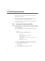
1.1 Introduction
This chapter describes the physical and functional properties of the
AT-AR240E and the AT-AR250E ADSL Bridge/Router.
1
Chapter 1
1.2 Product Description
Using industry-standard Discrete Multi-Tone (DMT) technology, the ADSL
device interfaces to any ITU G.dmt, UAWG, G.lite and ANSI T1.413, Issue 2
compliant, Central Office equipment at speeds of 8 Mbps downstream and
1 Mbps upstream (depending on the distance from the Central Office, selectable
in increments of 32kbps). The Central Office equipment provides
Asynchronous Transfer Mode (ATM) aggregation over ADSL on each copper
loop.
A fully integrated IP router featuring Network Address Translation (NAT)
automatically assigns local IP addresses and protects network security by not
advertising the internal address or network topology. A built-in Dynamic Host
Configuration Protocol (DHCP) Server assigns IP addresses to all LAN stations.
The AT-AR250E includes an integral 4-port Ethernet Bridge/Router supporting
a directly connected PC from any of its Ethernet ports. or a network of cascaded
LAN hubs.
The AT-AR240E and the AT-AR250E both offer Password Protection and User
Authentication (PAP/CHAP) with PPP to prevent inadvertent access to the
router through the Internet. It also enables Telnet management access.
2
Chapter 1
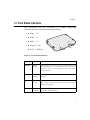
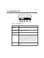
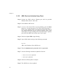
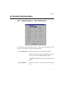
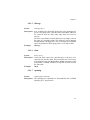
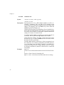
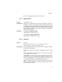
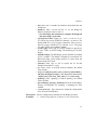
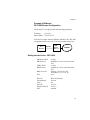
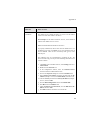
1.3 Front Status Indicators
NC
SY
R
ATM ACT
ALARM
SYNC
WE
PO
" Height : 1.5"
"Width : 8"
" Depth : 6"
"Weight : 1.5 lbs
"Color : Off White
light-weight
M
AR
AL
T
AC
M
AT
The AT-AR240E and the AT-AR250E are compact,
communications devices with the following dimensions:
POWER
Figure 1: Front Status Indicators
LED
COLOR
EXPLANATION
POWER
Green
(solid)
It will illuminate as soon as the device is powered ON and will
remain on till the device is turned OFF. If this LED remains OFF,
the device needs to be serviced. Please refer to the Repair
Service Procedure.
SYNC
Green
(solid)
It illuminates to indicate successful DSL connection to the
Network.
ALARM
Red
(solid)
It indicates the device encountering an error. If this LED remains
ON, it means it cannot sync up to the device. Check the cable
connections or settings.
ATM ACT
Green
(blinking)
The ATM Activity LED shows data traffic. During normal
operation, it should be blinking.
3
Chapter 1
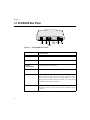
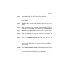
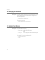
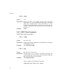
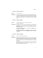
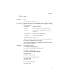
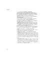
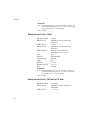
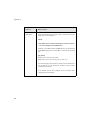
1.4 AT-AR240E Rear Panel
POWER
SYNC
ATM ACT
ALARM
DSL
POWER
ON
ETHERNET
USB
OFF
12V
RJ11
DSL
Port
Power
Switch
Power
Connector
RJ45
Reset Ethernet USB
Port
Port
Switch
Figure 2 : AT-AR240E Rear panel
EXPLANATION
4
DSL PORT
RJ-11 port for DSL connection and requires a RJ-11 cable (provided).
POWER SWITCH
Permits the device to be turned ON or OFF.
POWER
CONNECTOR
A receptacle for the Power Adapter.
RESET SWITCH
To return the device to factory settings.
ETHERNET PORT
Allows the AT-AR240E to establish a connection directly to a PC or a
Hub and requires a RJ-45 auto crossing cable (provided). It has 2
LEDs. The (green) LED remains solid when linked to an active
Ethernet port and will blink when there is traffic. The (yellow) LED
indicates the speed utilized by the device.
USB PORT
Allows a direct connection to a PC for greater flexibility and
simultaneous sharing of local resources and the ADSL line (cable
provided).
Chapter 1
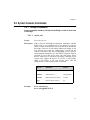
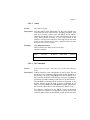
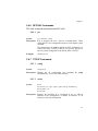
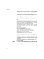
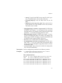
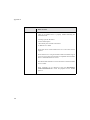
1.5 AT-AR250E Rear Panel
POWER
SYNC
ATM ACT
ALARM
DSL
POWER
RJ11
12V
DSL
Port
Reset
Switch
ETHERNET
1
Power
Connector
2
3
USB
4
Ethernet
Ports
USB
Port
Figure 3: AT-AR250E Rear panel
EXPLANATION
DSL PORT
RJ-11 port for DSL connection and requires a RJ-11 cable
(provided).
RESET SWITCH
To return the device to factory settings.
POWER
CONNECTOR
A receptacle for the Power Adapter.
ETHERNET PORTS
Allows the AT-AR250E to establish a connection directly to a PC or
a Hub from any of its 4 ports. It requires a RJ-45 auto crossing cable
(provided). The ports have the auto-crossing feature which allows
connection to any of the Ethernet ports. Each of the 4 ports have 2
LEDs. The (green) LED remains solid when linked to an active
Ethernet port and will blink when there is traffic. The (yellow) LED
indicates the speed utilized by the device. It will be lit when the
speed is at 100Mbps and will be off when the speed is 10Mbps.
USB PORT
Allows a direct connection to a PC for greater flexibility and
simultaneous sharing of local resources and the ADSL line (cable
provided).
5
Chapter 1
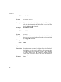
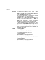
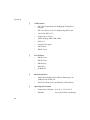
1.6 System Inter-operability
The ADSL device’s implementation of protocol standards ensures
inter-operability with PCs, LANs, Routers, Servers and Central Office
equipment such as voice and ATM switches. It also provides inter-operability
on the Physical, Data Link and Network layers.
The Physical Layer includes the hardware and electrical signaling
characteristics supported by the ADSL device’s Ethernet and IP router
interfaces. Compliance to ITU ADSL standards guarantees connectivity of the
ADSL device to the DSL Access Multiplexer (DSLAM) ports.
The Data Link Layer defines the transmission path of the data packets between
the two systems over the LAN and WAN physical links.
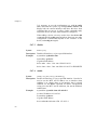
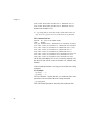
DSL
POWER
ETHERNET
12V
RJ-45
USB
ON
OFF
RJ-11
Figure 4: The AT-AR240E’s 10BaseT Ethernet port attaches directly to a
PC Ethernet port or an external Ethernet hub.
DSL
RJ-11
POWER
ETHERNET
USB
RJ-45
Figure 5: Any of the 4 Ethernet ports of the AT-AR250E attach directly to a
PC Ethernet port or an external Ethernet hub.
6
Chapter 1
1.7 System Interface (LAN)
The AT-AR240E supports Ethernet LANs through its {RJ-45} Ethernet
10BaseT port which acts as a mini-hub. AT-AR250E may be configured to
cascade hubs through its {RJ-45} Ethernet 10/100BaseT ports which acts as a
mini-hub too.
DSL
POWER
ETHERNET
USB
ON
OFF
12V
RJ-11
RJ-45
Hub1
Hub2
Figure 6: Demonstrates cascading hubs using the Ethernet port of the ATAR240E.
DSL
RJ-11
POWER
ETHERNET
USB
RJ-45
Hub1
Hub2
Figure 7: Demonstrates cascading hubs using any of the 4 Ethernet ports of
the AT-AR250E.
7
Chapter 1
1.8 System Interface (DSL)
The ADSL device is connected by a RJ-11 connector to an ADSL line.
Central
Office
POWER
DSL
ETHERNET
USB
ON
Ethernet Hub
OFF
RJ-11
ADSL
Wall
Jack
12V
RJ-45
AT-AR240E
POTS
Splitter
DSLAM
Wall
Jack
Telephone
Figure 8: For a typical installation, the voice terminals of the splitter are
connected to the existing house phone wiring. A separate line is
connected from the data terminals of the splitter to a RJ-11 wall
jack. The ADSL device is connected through the DSL {RJ-11}
jack on the Rear panel to this ADSL {RJ-11} wall jack.
1.9 Installation and Configuration
For information on:
•
Hardware installation procedures
•
Connecting the PC to the ADSL device
•
How to install the USB driver
•
Configuring the PC for the USB
Please refer to the User’s Manual
8
Chapter 2
CHAPTER
2
OPERATION
2.1 Introduction
The following section describes the ADSL devices, their Ethernet and USB
ports transmission, ATM and ADSL transmission as well as Security and
System Management.
9
Chapter 2
2.2 System Description
The ADSL devices provide asymmetric data transport from the Customer’s
network to a DSLAM at the Central Office. It can be deployed over existing
copper loops already supporting a plain old telephone service (POTS).
The ADSL devices configuration consists of the device at the Customer
premises interfacing with an ADSL standard compliant line card in a Digital
Subscriber Line Access Multiplexer (DSLAM) at the Central Office. Its very
rich feature set includes an easy-to-use Setup Wizard and DHCP support for
Plug-and-Play installation. It also provides an extensive Firewall for network
protection, and VPN capabilities for reduced cost of remote access
communications.
The AT-AR240E and the AT-AR250E can be configured and managed locally
or remotely via a PC connected to the remote unit, or using the Command Line
Interface (CLI) through a Telnet session, or through a Windows-based
configuration tool.
The ADSL devices support Permanent Virtual Circuits (PVC). Each PVC is
represented by a numeric pair denoted as a Virtual Path Identifier (VPI) and
Virtual Circuit Identifier (VCI). A VPI is a number used to switch a logical
group of Virtual Circuits as a unit. A VCI is a number assigned to a single
circuit to distinguish its cell traffic from other circuits. Each 12-bit VPI has the
address range 0-4095 and each 16-bit VCI has the address range 0-65535.
The ADSL devices supports all PCs using standard Ethernet 10BaseT or
100BaseT and TCP/IP protocols.
2.3 Routing
The ADSL devices include full-featured integrated IP routers. To route a
packet, two basic functions are used:
1 A path determination function- enables the device to select the
most appropriate interface to
transmit a packet.
10
Chapter 2
2 A switching function
- allows the device to accept a
packet from one protocol and
forward it to a second protocol.
When routing, the device accesses routing address tables to determine the best
path for each packet to take. Routing tables can either be seeded as a static path
or built dynamically from broadcast packet information. The ADSL devices
switch the internet protocol (IP) between the 10BaseT/LAN interface and the
ADSL/ATM interface. The device also supports the Routing Information
Protocol, RIP[v1.0] and RIP[v2.0] to collect path routing information.
2.4 Network Address Translation
Network Address Translation (NAT) provides a mechanism for private
networks to access registered networks, such as the Internet, without requiring a
registered subnet address. NAT eliminates the need for host IP numbering and
allows the same IP addresses to be used in multiple Internet.
With NAT, the LAN addresses are private. These addresses are translated to
public IP addresses when IP addresses are forwarded. The NAT translation
function is compatible with standard IP routing.
11
Chapter 2
2.5 Static Routing
The ADSL devices support IP Static Routing. With Static Routing, a Network
Administrator makes specific LAN IP addresses available for WAN access.
The easiest form of routing is establishing predefined routes through a network.
A router that has been programmed for static routing forwards packets out of
predetermined ports. Configuring static routing to a sub-network avoids the
overhead of dynamic routing.
The many benefits of Static Routing are that they form a more safe and secure
network system, since there is only one path a network is connected in to and
out of.
Another benefit is that it is more efficient in Resource Management. Since it
uses less bandwidth, the router CPU cycles trying to calculate routes are not
wasted and it also conserves memory.
2.6 Bridging
The ADSL devices support IEEE 802.1d Transparent Learning Bridge
connecting Ethernet LANs. Ethernet Bridging is a Data Link Layer function
connecting Ethernet addresses, independent of higher layer Internet protocols.
When IP routing is disabled and bridging is enabled in the unit, the incoming
frames are forwarded based on MAC layer addresses. The ADSL device
supports Transparent Bridging, which forwards frames one hop at a time
towards the destination. The Learning Bridge, which performs MAC address
learning, reduces traffic on the network by maintaining a table of MAC
addresses and interfaces associated with each address.
12
Chapter 2
2.7 Point-to-Point Protocol
The ADSL devices support PPP over ATM. PPP is a WAN protocol
transmitting multi-protocol data grams over serial links. PPP addresses are:
• Standardized Internet encapsulation of IP over point-to-point links
• Used in assignment and management of IP address
• Asynchronous (start/stop) and bit-oriented encapsulation
• Network protocol multiplexing
• Based on link configuration
• Link quality tested
• Based on error detection
• An option to negotiate for network layering addresses and data
compression
To accomplish the above functions, PPP includes the following protocols:
• Link Control Protocol (LCP)
: To establish, configure and test the
data link connections.
• Network Control Protocol (NCP): TCP/IP Routing Internet Protocol
Control Protocol (IPCP)
• PAP/CHAP Security Protocols
: Establish a link from the point of
origin to the point of destination.
PPP sends LCP frames to configure and (originally) test the data link. After the
link has been established and facilities have been negotiated, the originating
PPP sends NCP frames to choose and configure IP. This link remains until LCP
or NCP frame close the link. PPP maintains the local address to be translated
and the pool of addresses from which to allocate outside addresses.
13
Chapter 2
2.8 Security
The ADSL devices include security features such as Password Protection, User
Authentication, Password Authentication and Protocol/Challenge Handshake
Authentication Protocol (PAP/CHAP) to prevent unauthorized or inadvertent
access to the router through the Internet.
PAP/CHAP must be enabled by both ends of the link. The following sequence
describes how authentication occurs:
PAP verifies passwords between the ADSL devices using a two-way
handshake. A device (known as the Peer) sends the system name and
password to a destination device (or other PPP servers). The
destination ADSL device (known as the Authenticator) checks the
password against the configured password and returns either an
‘accept’ or a ‘reject’ reply.
CHAP provides additional security with a three-way handshake. The
‘Authenticator’ challenges the originating ADSL device by
generating a random number and sending it along with the system
name. The ‘Peer’ then applies a one-way encryption algorithm to the
random number and returns this encrypted information along with the
system name. The Authenticator then runs the same algorithm and
compares the result with the expected value. This authentication
method depends upon a password known only to both ends.
The ADSL devices support Virtual Private Networks (VPNs) with PPTP and
L2TP.
14
Chapter 2
2.9 PC Setup for Telnet
Connect any of the ADSL device’s Ethernet ports with the provided Ethernet
cable (yellow) to the PC’s NIC card.
The user needs to set his PC IP address to be of the same subnet as the device.
For Example: The default IP address of the device is 10.0.0.1. The PC
IP address can be set to 10.0.0.2.
On a Windows PC (example: Windows 95, 98, Me or 2000), select Start and
then the Run option. Verify the Telnet link by entering the following string in
the Open dialog box:
For Example:
ping 10.0.0.1
Click OK and a DOS window will pop up with the following reply:
pinging 10.0.0.1 with 32 bytes of data
Reply from 10.0.0.1: bytes=32 time=_ TTL=_ (ICMP reply packet from 10.0.0.1)
If “Request timed out” OR any other error message is received, check the PC IP
Address and restart the PC.
15
Chapter 2
2.10 USB Port Setup
The Rear panel of the device also includes an USB port marked “USB” for
direct PC connection. Connect the ADSL device’s USB port with the provided
USB cable (grey) to the PC’s USB port. Load the Driver provided on to the PC
to simulate Ethernet connections.
The user needs to set his PC IP address to be of the same subnet as the device.
For Example: The default IP address of the device is 10.0.0.1. The PC
IP address can be set to 10.0.0.2.
On a Windows PC (example: Windows 95, 98, Me or 2000), select Start and
then the Run option. Verify the Telnet link by entering the following string in
the Open dialog box:
For Example:
ping 10.0.0.1
Click OK and a DOS window will pop up with the following reply:
pinging 10.0.0.1 with 32 bytes of data
Reply from 10.0.0.1: bytes=32 time=_ TTL=_ (ICMP reply packet from 10.0.0.1)
If “Request timed out” OR any other error message is received, check the PC IP
Address and restart the PC.
Follow the instructions on loading the Driver provided and configuring the
PC from ‘Connecting the PC to the ADSL device - USB Installation’ in the
User’s Manual.
16
Chapter 2
2.11 ADSL Transmission
The ADSL transmission is based on ITU G.dmt, UAWG, G.lite and ANSI
T1.413 standard DMT line codes. The device’s DMT line rate is up to 8 Mbps
downstream and up to 1 Mbps upstream. The DMT transceiver is rate adaptive
and capable of providing faster rates over shorter distances and slower rates
over longer distances. The ADSL device’s transceiver can adjust to changing
line conditions to maximize the data throughput over the given distance. Rate
adaptation is supported in increments of 32 kbps.
A Service Provider will set the ADSL device’s data-rates at the DSLAM
network interface depending on the service contract the subscriber buys. The
upstream and downstream rates can be set in various ways:
• Maximum bit rate
• Minimum bit rate
• A range between minimum and maximum bit rates
• Maximum bit rate with a threshold in Decibels (dB)
2.12 ATM Transmission
ATM over ADSL transmission is based on ITU G.DMT, UWAG, G.Lite and
ANSI standard T1.413, Issue 2, standards incorporating ADSL Forum TR-0002
“ATM over ADSL Recommendations”.
17
Chapter 2
2.13 BOOTP Download Procedure
NOTES:
•
These are generic directions for successfully updating the Firmware on to
the ADSL device via BOOTP.
•
There are many Firmware versions. Please contact Customer Service
before beginning the download for additional information.
•
Connect the ADSL device’s Ethernet port with the provided Ethernet
cable to the PC’s NIC card.
2.13.1
Launching the Firmware Upgrade Utility
NOTE: The MAC address of the ADSL device is required before beginning
the download procedure. If the MAC address is not known, follow the
steps as shown below:
=
Start a DOS application and type in the following command:
telnet <IP>
<IP> is the IP address of the ADSL device.
password: ********
logged on; type ‘@close’ to close connection.
10.0.0.1> chips info
ADSL USB Modem - ADSL device version 1.35 (Dec. 13 2000)
Machine Name:
MAC address: 0:e0:b2:0:0:0
=
=
=
18
Enter the Administrator’s password (default is password).
Type in the following command:
10.0.0.1>chips info
The MAC address will be shown on the screen.
Chapter 2
Step 1 Launch the Firmware Upgrade Utility by double-clicking the
BootP.exe.
Step 2 Enter the IP address of the ADSL device.
Step 3 Enter the MAC address of the ADSL device (as shown above).
Step 4 Select Choose File icon to locate the image file from the Firmware
Upgrade Utility screen.
Step 5 The Firmware Upgrade Utility has been activated.
Step 6 If the ADSL device has a Console port, follow the instructions as
shown in Section C.
19
Chapter 2
2.13.2
ADSL Device’s Activation Using Telnet
Step 1 Connect the ADSL device’s Ethernet port with the provided
Ethernet cable to the PC’s NIC card.
Step 2 Power ON the ADSL device.
Step 3 As soon as the Alarm LED (red) starts flashing, press the Reset
button for a second and release. The LEDs in the Front panel i.e.:
Power, Sync, and the ATM ACT will begin to flash. The image is
now being downloaded from the Firmware Upgrade Utility. If the
Alarm LED (red) stops flashing before the Reset button is pushed,
power OFF the ADSL device and try step 2 and 3 again.
Step 4 Wait for the Sync LED to begin flashing.
Step 5 Open a DOS window and type in the following command:
telnet <IP>
<IP> is the IP address of the ADSL device.
Step 6 Enter the Administrator’s password (default is password).
Step 7 Issue the following commands to update the firmware:
• flashfs rewrite boot.bin <password>
• flashfs update <password>
Step 8 Wait for the Flash update to complete.
Step 9 The ADSL device is now updated.
20
Chapter 2
2.13.3
ADSL Device’s Activation Using Console Port
Step 1 Connect the device’s Ethernet port with the Ethernet cable to the
PC’s NIC card.
Step 2 Connect a Serial cable from the PC’s Serial port to the Console port
of the device.
Step 3 Launch Hyper Terminal or ProComm and set the connection to:
Bits per second: 9600
Data bits: 8
Parity: None
Stop bits: 1
Flow Control: None
Step 4 Power ON the unit.
Step 5 The words StartUp from [Bootp/Ethernet/USB/Flash] ,,, will
show in Hyper Terminal. Promptly, press the “e character” on the
keyboard to initiate the Firmware update sequence. A series of dots
across the screen means the file is being downloaded.
Step 6 Wait for the new Firmware image to be updated and the device
successfully rebooted.
Step 7 Type the following commands in the Hyper Terminal application:
• flashfs rewrite boot.bin <password>
• flashfs update <password>
Step 8 Wait for the Flash update to complete.
Step 9 The ADSL device is now updated.
21
Chapter 2
2.14 Updating Firmware via TFTP
NOTES:
22
•
These are generic directions for successfully updating the Firmware on to
the device via TFTP.
•
There are many Firmware versions. Please contact Customer Service
before beginning the download for additional information.
•
Connect the ADSL device’s Ethernet or USB port with the provided
Ethernet cable to the PC’s NIC card or USB port.
Step 1:
Launch the Firmware Application by double-clicking on the file
“TFTP.exe”.
Step 2:
Enter the IP address of the ADSL device (default is 10.0.0.1) or the
one provided by the Service Provider.
Chapter 2
Step 3:
Select Choose File from the Firmware Upgrade Utility.
Step 4:
In the pop-up dialog box, locate the Image File for downloading and
select Open.
Step 5:
NPImage File: Select Choose File from the Firmware Upgrade
Utility.
Step 6:
In the pop-up dialog box, locate the NPImage file that needs to be
downloaded and select Open. The file name may be ‘NPimage.crc’.
Step 7:
Boot File: Select Choose File from the Firmware Upgrade Utility.
Step 8:
In the pop-up dialog box, locate the Boot file for downloading and
select Open. The file name may be ‘Boot.crc’.
Step 9:
Enter the Administrator’s password of the ADSL device in the
Password field (default is password).
Step 10:
The Firmware Upgrade Utility is now ready for downloading. Please
ensure that the ADSL device is connected and powered ON for at
least a minute.
Step 11:
Select Update Firmware button to initiate the download procedure.
Step 12:
In the first phase, the images will be downloaded and the following
screen will appear showing images being downloaded.
23
Chapter 2
24
Step 13:
It is very important that the device is not powered OFF at this point.
Turning OFF the device could cause it to be in-operational. Please
wait for at least 3 minutes for the device to be ready as this is the
minimum required time for the memory of the device to be totally
reprogrammed with the new information.
Step 14:
The device will be ready when the Alarm LED (red) goes off and the
Sync LED (green) starts flashing.
Step 15:
Congratulations! The ADSL device is now ready.
Chapter 3
CHAPTER
3
APPLICATIONS
3.1 Introduction
The ADSL devices allow Network Service Providers (NSPs) such as Regional
Bell Operating Companies (RBOCs), Competitive Local Exchange Carriers
(CLECs), Internet Service Providers (ISPs) and independent telephone
companies to expeditiously and economically provide high-speed data access to
their customers.
Some typical applications are described on the following pages.
25
Chapter 3
3.2 High-Speed Internet Access
Figure 9:
Demonstration of High-Speed Internet Access
For high-speed Internet Access, connect an ADSL device to a DSLAM. The
DSLAM back haul connects to any Content Provider, Corporate Headquarters
or to another ADSL device.
A single Internet Service Provider (ISP) can assign a static IP address to each of
the Customer’s connected equipment.
It may, however, be more practical to allow the ADSL device’s DHCP server to
automatically assign IP addresses to customer equipment.
26
Chapter 3
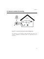
3.3 Remote Locations Connectivity
Figure 10: Connectivity with remote locations for applications
The ADSL device can be utilized as a link between the Central Office to the
Corporate Headquarters and Remote Offices for applications such as
e-commerce.
27
Chapter 3
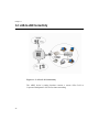
3.4 LAN-to-LAN Connectivity
Figure 11: LAN-to-LAN Connectivity
The ADSL device’s routing functions connect a remote office LAN to
Corporate Headquarter LANs for fast intra-networking.
28
Chapter 4
CHAPTER
4
ADVANCED CONFIGURATION
4.1 Introduction
This chapter introduces the Advanced Mode of the ADSL device’s GUI. The
GUI is provided in a CD and requires configuration. If the GUI has not been
configured, please refer to Chapter 3 - Configuration in the User’s Manual.
For more information on Configuration of the ADSL devices, please refer to the
Help File of the GUI software.
29
Chapter 4
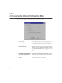
4.2 Accessing the Advanced Configuration Mode
The GUI has 3 options to begin accessing the ADSL devices.
30
•
Easy Setup
- The default mode to be chosen by the User. It
is explained in detail in the User’s Manual.
•
Advanced Setup
- Allows the User to access and configure the
ADSL device’s advanced statistics. Choose
the Advanced SetUp after logging in to the
GUI.
•
Automatic Configuration - The initial Configuration File used to set up
(from ISP supplied file)
the device for use with the Service Provider.
•
Cancel
- Allows the User to exit the GUI.
Chapter 4
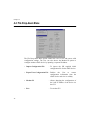
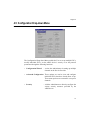
4.3 Main Statistics Screen
Once the Advanced Setup is selected, the Main Statistics screen will be
displayed.
Disconnects the configuration session
to the ADSL devices.
•
•
Exits Configuration
Loads online Help.
The Main Statistics screen provides a quick view of the current
configuration.
It allows the Administrator to configure and access the internal data via the
following 4 Drop-down Menus:
•
File Menu
•
Configuration Menu
•
Operation Menu
•
Help Menu
31
Chapter 4
4.4 File Drop-down Menu
The File Drop-down Menu option enables the User to save and restore valid
configuration settings. The User can also choose the Modem IP option to
configure another ADSL device by inputting a separate IP address.
• Import Configuration File
- To import the ISP supplied initial
configuration file for the ADSL device.
• Export/View Configuration File - Enables
the
User
to
extract
configuration information from the
ADSL device and view its validity.
32
• Modem IP
- Allows changing the configuration of
the LAN IP address of the device via
the GUI.
• Exit
- To exit the GUI.
Chapter 4
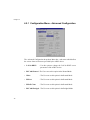
4.5 Configuration Drop-down Menu
The Configuration Drop-down Menu enables the User to set up multiple PVCs,
modify individual PVCs, set the ADSL device’s security or set the protocol
parameters through the following functions:
• Configuration Wizard
- Assists the Administrator in setting up multiple
channels to the Service Provider.
• Advanced Configuration- These options are used to view and configure
individual PVCs that have already been set up.
These menu options are not meant to set up new
channels.
• Security
- Aids the Administrator to directly configure the
various security measures provided by the
ADSL device.
33
Chapter 4
4.5.1 Configuration Menu - Advanced Configuration
The Advanced Configuration drop-down Menu has a sub-menu which defines
the various forms of measures provided by the ADSL device.
• LAN & DHCP
- Use this option to change the LAN & DHCP server
parameters of the ADSL devices.
• RFC1483 Routed - The User can use this option in the Routed Mode.
• IPOA
- The User can use this option in the Routed Mode.
• PPPOA
- The User can use this option in the Routed Mode.
• PPPoE Client
- The User can use this option in the Routed Mode.
• RFC1483 Bridged- The User can use this option in the Bridged Mode.
34
Chapter 4
• PPPoE Relay
- The User can use this option in the Bridged Mode.
• RFC1483 Gateway- The User can use this option in the Routed Mode.
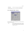
4.5.2 Configuration Menu - Security
The Security Menu has a sub-menu which defines the various forms of security
measures provided by the device.
• NAT
- Used to configure the Network Address Translation
(NAT) on the channels that have been set up. It can be
used to share a single IP address among multiple
computers on the LAN.
35
Chapter 4
• Forwarding
- Allows configuration of the ADSL device’s IP
forwarding tables.
• PPTP
- The Point-to-Point Tunneling feature creates secure
Virtual Private Networks (VPNs).
• Filter
- Allows the User to use the ADSL device as a Firewall.
• Change Password - Option for the Administrator
Administration password.
• User Access
36
to
change
the
- Manages a list of User who have Read-Only access to
the ADSL device.
Chapter 4
4.6 Operation Drop-down Menu
4.6.1 Operation Menu - View Performance
The Operations Drop-down Menu allows viewing of the performance of the
device. Its sub menu provides the following options:
• View Performance - Under this option are 2 of the following options:
The IP option retrieves the essential statistics from the
device for TCP, UDP, ARP,RAW and IP traffic.
The DSL option displays performance statistics of the
device.
• Restart Modem
- It allows the User to restart the device through the
GUI.
37
Chapter 4
4.7 Help Menu
The Help Drop-down Menu option enables the User to access the Help File.
• Contents
- Shows the contents of the Help File for additional
assistance.
• About GUI
- Shows the Configuration GUI version number.
• About Firmware - Shows the Firmware and Image version of the ADSL
device.
IMPORTANT
38
: Hitting F1 at any point of configuration, shows
the relevant portion of the Help File.
Chapter 5
CHAPTER
5
COMMAND LINE INTERFACE COMMANDS
5.1 Introduction
This chapter provides information on the System Console Commands, the
ADSL Commands and the Advanced CLI Commands.
39
Chapter 5
5.2 Changing the Password
Description: After the system has booted up, the password needs to be set up,
before configuring the device in the Router or Bridge Mode.
Enter the old password
....> flashfs password <old password>
Enter the new password
....> flashfs config password <new password>
5.3 Update Flash Memory
Description: To update Flash File System.
....> flashfs update updates Flash File System
OR
....> config save
saves configuration files to Flash File System
For example: To save the configuration file
....> config save <password>
....> restart
40
Chapter 5
5.4 System Console Commands
5.4.1
Bridge Commands
Console commands should be prefixed with the Bridge in order to direct them
to the Bridge.
5.4.1.1
device add
Syntax:
device add <device>
Description: Adds a device to the Bridge configuration. Attempts to add the
bridge itself or an existing device to the bridge are rejected.
There is a limit on the number of devices that can be attached to
the bridge. If a device is successfully added to the bridge, it will
only become active after the configuration is saved and the
system is rebooted. If the device being added is from a process
which supports multiple devices, the /DEVICE attribute must be
specified as part of the device name. The table below shows
devices which may be attached to the bridge, although not all
systems may support all devices. If a device is successfully
added to the bridge, it will only become active after the
configuration is saved and the system is rebooted.
Example:
Device
Remarks
Source
lec1
Forum LAN emulation
alecjade
ethernet
Ethernet driver
edd, etherjade
rfc1483
RFC1483 protocol (PVC)
rfc1483
ppp
Point-to-Point protocol
pp
device add ethernet
device add ppp/DEVICE=2
41
Chapter 5
5.4.1.2
Syntax:
device delete
device delete <device>
Description: Deletes a device from the bridge configuration. The changes
will only take place after the configuration is saved and the
system is rebooted. The syntax of the device name is the same as
that for the device add command.
Example:
device delete rfc1483
5.4.1.3
device list
Syntax:
device list
Description: Lists all the devices that are currently attached to the bridge. It
does not show the stored configuration (which can be seen with
the config print command).
Example:
device list
5.4.1.4
filter
Syntax:
filter
Description: Shows the current contents of the bridge’s filter table. The MAC
entries for each device are shown together with the time that the
MAC address was last seen by the bridge. The command also
shows the current filter ageing time (seconds), and the number
of creation failures since the system was started. Creation
failures occur when there is no room left in the filter table for a
new entry.
Example:
filter
42
Chapter 5
5.4.1.5
filterage
Syntax:
filterage [<age>]
Description: Sets, or displays the filter table ageing time (if no arguments are
given). The ageing time is the time after which MAC addresses
are removed from the filter table when there has been no
activity.
The time is specified in seconds and may be any integer value in
the range 10…100,000 seconds. This value may also be changed
through SNMP. Changing the value of filterage has immediate
effect. By default, the filter ageing time is set to 300 seconds.
Example:
filterage
5.4.1.6
flush
Syntax:
flush [<port>]
Description: Allows the MAC entries for a specified port, or all ports, to be
removed from the filter table. The port number for a device may
be determined using the device list or status commands. If the
port number is omitted, all entries for all ports are removed from
the filter table.
Example:
flush
5.4.1.7
spanning
Syntax:
spanning [sub-command]
Description: The spanning tree commands are documented in the “ATMOS
Spanning Tree” specification.
43
Chapter 5
5.4.1.8
status
Syntax:
status
Description: Shows the status of the bridge and its ports. The status
information for a port includes the SNMP type information
about time exceeded packets, packets discarded, etc. It also
includes the broadcast history of the port over the last five
seconds. A high water mark of packets queued on the bridge for
this device.
Example:
status
5.4.2 DHCP Client Commands
DHCP Client console commands.
5.4.2.1
config
Syntax:
dhcpclient config
Description: Displays the current configuration of the DHCP client, including
selected DHCP options.
Example:
adsl> dhcpclient config
5.4.2.2
help
Syntax:
dhcpclient help <command | all>
Description: Provides help on the Console commands. Specifying the
command name gives detailed help, and specifying the argument
all gives detailed help on all commands.
Example:
adsl> dhcpclient help
Help is available on the following commands:
config help pool status trace untrace
44
Chapter 5
5.4.2.3
status
Syntax:
dhcpclient status [all]
Description: Provides DHCP status information for the active bound lease
associated with each valid interface, including IP address, time
until lease renewal, subnet mask and DHCP server address.
Including the all flag shows, for each valid interface, the active
lease, leases which are being, or have been offered to the
interface, and any leases which are still being held by the client
which are not currently active (since a single interface can only
have one active lease at a time).
Example:
adsl> dhcpclient status
DHCP Client Lease Status (active lease only)
Interface 'ethernet'
5.4.2.4
Syntax:
Status
Server ID
IP address
Subnet mask
Renewal
*ACTIVE*
192.168.219.151
192.168.219.1
255.255.255.255.0
31 secs
IP Commands
ip device add <i/f> <type> <file> [mtu <size>] [<IP address>|dhcp] ip
device
Description: Adds an interface to the configuration of the IP stack. The last
parameter of the command would normally be the IP address of
the interface; use of the string dhcp causes the IP address to be
discovered by the DHCP client software. Using the flag dhcp on
an interface precludes running a DHCP server on that interface.
The ip device command lists the current configuration of any
devices attached to the IP stack. A device configured to use
DHCP will show dhcp in the IP address column, followed by
the actual IP address discovered and bound by DHCP, if any.
For interfaces configured to use DHCP, saving configuration
only marks the interface as using DHCP; it does not save the
actual IP address discovered by DHCP, which must be renewed.
45
Chapter 5
Example:
A useful method of automatically configuring suitable IP
devices is to put a device add statement into the file //isfs/
resolve and downloading it upon booting the image.
adsl> ip device add ethernet ether //edd dhcp
adsl> ip device
#
type
dev file
IP address
device ethernet ether //edd
mtu 1500 dhcp
5.4.3 DHCP Server Commands
DHCP Server Console commands.
5.4.3.1
config
Syntax:
dhcpserver config [add <text>|confirm|delete|flush]
Description: This command displays or edits the current configuration of the
DHCP server. To display current configuration, provide no
arguments to the command. Use of the add argument adds the
line <text> to the configuration file. Use of the confirm
argument reparses the configuration file, confirming the changes
made if the parse is successful. Use of the delete argument
deletes the last line from the configuration file. Use of the flush
argument deletes the whole configuration. Following any
change to the configuration file, it is necessary to confirm the
changes, issue a flashfs update to commit the change to
FLASH, and then restart the system before the changes can take
effect.
Example:
adsl> dhcpserver config
allow unknown-clients;
allow bootp;
subnet 192.168.219.0 netmask 255.255.255.0 {
range 192.168.219.10 192.168.219.30;
max-lease-time 5000;
}
46
Chapter 5
adsl> dhcpserver config flush
Configuration file flushed.
adsl> dhcpserver config
Current DHCP server configuration
(Issue dhcpserver config confirm followed by flashfs update
to confirm new configuration).
5.4.3.2
help
Syntax:
dhcpserver help <command | all>
Description: Provides detailed help on the Console commands. Specifying all
gives specific help on all available commands.
Example:
adsl> dhcpserver help
Help is available on the following commands:
config help pool status trace untrace
5.4.3.3
status
Syntax:
dhcpserver status
Description: Provides a summary of all leases of the server on each interface
and shows remaining available IP addresses.
47
Chapter 5
Example:
adsl> dhcpserver status
DHCP Server Lease Status
Interface “ethernet”
IP address
| Client UID
| Expiry
--------------------+----------------------------+-----------------192.168.219.1 | 01:00:20:af:20:6f:59 | 11 hours
192.168.219.2 | 01:00:20:af:11:2a:ac | 8 hours
192.168.219.3 | Myclient
| 140 seconds
192.168.219.4 | 00:20:af:20:00:2b
| 2 days
192.168.219.5 | <unknown>
| Never
192.168.219.6 | <unknown>
| Never
192.168.219.7 | <unknown>
| Never
192.168.219.8 | <unknown>
| Expired
192.168.219.9 | <unknown>
| Expired
192.168.219.10 | Foobarbozzle
| Expired
5.4.4 NAT Commands
5.4.4.1
ip nat
Syntax:
ip nat add | delete <i / f name>
Description: Adds or removes NAT from the named interface. The interface
name is the name as listed by the ip device command. NAT
should be enabled only on the interface connecting to the public
network, not the interface connecting to the private network.
Example:
adsl> ip nat add ethernet
48
Chapter 5
5.4.4.2
event
Syntax:
nat event [n]
Description: Displays or sets the current level of event tracing in the NAT
process. Larger values of n result in more verbose trace output.
All trace messages are printed as background output, and
therefore will not be displayed asynchronously on the console
unless the event show command has been issued.
Example:
adsl> nat event
Event level: 1
adsl> nat event 2
5.4.4.3
help
Syntax:
nat help [command]
Description: Lists NAT commands.
5.4.4.4
Syntax:
inbound
nat inbound list
nat inbound add <i/f> <port>/<proto> <new IP> [quiet]
nat inbound delete <#>
nat inbound flush
Description: Enables the user to list or to set up a series of rules, to determine
what happens to incoming traffic. By default, all incoming
packets, other than packets arriving in response to outgoing
traffic, will be rejected.
The nat inbound add command allows packets arriving on a
specific port and IP protocol to be forwarded to a machine on the
private network.
<i/f> is an interface name as shown by the nat interface list
command.
49
Chapter 5
Example:
5.4.4.5
<port> is the destination UDP or TCP port number to match in
the incoming traffic.
<proto> is the IP protocol, either udp or tcp.
<new IP> is the new IP address on the private network which
the packet’s destination IP address should be translated to.
If a rule is added for an interface on which NAT is not enabled,
the rule is added, but a warning is printed to alert the user.
quiet is a special option which should not normally be issued at
the console, and causes this warning to be suppressed. The quiet
option is automatically added by NAT to when writing its
configuration to flash; this is because when a system boots, the
NAT process reads in these rules before IP has registered any
interfaces.
nat inbound list shows the current rules for inbound traffic,
including all the arguments to the nat inbound add command.
nat inbound delete removes a rule, where <#> is the rule
number as shown by the nat inbound list command.
nat inbound flush removes all the rules.
adsl> nat inbound add ethernet 80/TCP 192.168.219.38
adsl> nat inbound list
# InterfacePort/IP ProtocolNew IP address
1 ethernet80/tcp192.168.219.38
2 rfc148321/tcp192.168.219.40
adsl> nat inbound delete 2
protocol
Syntax:
nat protocols
Description: Lists the Application Level Gateways (ALGs) provided in the
current image in order to support particular higher-level
protocols, and the port or ports which each ALG monitors.
50
Chapter 5
Example:
5.4.4.6
adsl> nat protocols
NamePort/IP protocol
ftp21/tcp
sessions
Syntax:
nat sessions <i/f> [all | summary]
Description: Displays active NAT sessions on the interface <i/f>.
A session is a pair of source IP addresses and port numbers and
corresponding new port numbers that NAT regards as one side
of an active connection. For each active TCP or UDP session,
the source/destination IP address, port number, the local port
number and the age of the session are printed.
all causes the sessions command to print out information on
every session, including timed out sessions. The sessions
command only shows active sessions.
summary shows total of active, timed out and available
sessions.
Example:
adsl> nat sessions ppp
Protocol
Age
NAT
port
Private address/
port
Public/address
port
TCP
34
1024
192.168.219.38/35
194.129.50.6/21
Protocol
Age
NAT
port
Private address/
port
Public/address
port
TCP
10
1025
192.168.219.64/35
185.45.30.30.80
Total : 2 sessions active
101 sessions timed out
126 sessions available
51
Chapter 5
5.4.5 PPP Commands
PPP commands are prefixed with PPP.
5.4.5.1
channels
Description: A channel is a single PPP connection and is numbered from 1.
Many PPP Console commands affect only a single channel and
is prefixed with the channel number.
5.4.5.2
5.4.5.2.1
Console Commands
<channel> clear
Syntax:
<channel> clear
Description: Clears all aspects of the channel back to the default settings. If
there is an active connection, it is torn down.
5.4.5.2.2
<channel> enable
Syntax:
<channel> enable
Description: Sets the enable flag for a PPP channel. By default, this is
disabled.
5.4.5.2.3
<channel> event
Syntax:
<channel> event [<n>]
Description: Read or set the overall trace output level. Configuration saving
does not save this value. The default event level is 1.
52
Chapter 5
Event levels are:
5.4.5.2.4
1
only very serious errors reported (default)
2
definite protocol errors or very significant events reported
3
links going up/down are reported
4
every packet and significant state change is reported
5
every packet sent/received is disassembled and hex is dumped
<channel> disable
Syntax:
<channel> disable
Description: Clears the enable flag for a PPP channel and is the default
setting. Disabling does not remove other configured information
about this channel. By default, all channels are disabled.
5.4.5.2.5
<channel> interface
Syntax:
<channel> interface <n>
Description: Logically associates the specified channel with the specified
interface. Interface 1 is always the router port. It should be used
for any PPP channel over which IPCP communication with the
local system’s IP router is desired. Other interfaces can be
created for bridging. A single PPP channel can only be
associated with a single interface, or a single tunnel.
Use info to find the current setting.
Calling with n=0 removes any association and is the default
state.
53
Chapter 5
5.4.5.2.6
Syntax:
<channel> pvc
<channel> pvc [[<port>] <vpi>] <vci> [ip | mac] [listen]
<channel> pvc none
Description: Attach an ATM PVC to the given PPP channel. The port as well
as the VPI (default is 0), and the VCI can be specified (only for a
multi-port device).
The allowable range of the ports, VPI and VCI depends on the
ATM driver. Normal limits are 0 only for VPI and 1 to 1023 for
VCI.
If a single argument none is supplied, any current connection is
torn down. This is equivalent to svc none on the channel.
In the PPP state machine, providing a link of this form causes
the link to be ‘up’. Enable must also be used, to allow the link to
become operational.
The IP or mac indicates which form of data is transported over
the connection: one is IP data (controlled by the IPCP protocol),
or it is the MAC data (for BCP). If neither is provided, IP is
assumed. If the channel is not linked to an interface, and the
channel is for IP data, the channel is linked to interface 1.
If the channel is not linked to an interface, and the channel is for
MAC data, the channel is linked to interface 2. Providing a PVC
setting changes any SVC setting. See the svc command.
It is possible for a PVC to become ‘down’ in the PPP state
machine even though the PVC is still there, for example, due to
an authentication failure. If in this state, an incoming packet will
cause the PPP state machine to go ‘up’.
If listen is specified then this is the server end of a PVC. It will
not send out PPP Configure Requests until it first receives a
packet over the PVC. When a connection is torn down it goes
returns to this state.
Use the info command to read this information. By default, a
channel has no connection information.
54
Chapter 5
Example:
5.4.5.2.7
ppp 3 pvc 3 32set channel 3 to be (VPI=3, VCI=32)
ppp 4 pvcread PVC settings for channel 4
ppp 5 pvc 0remove any PVC settings from channel 5
<channel> qos
Syntax:
<channel> qos [cbr | ubr] [pcr <pcr-tx> [<pcr-rx>]]
Description: Specify that the VC for a PPP channel should be Constant Bit
Rate or Unspecified Bit Rate, and (optionally for UBR) give a
Peak Cell Rate for the connection. If two values are specified
then they are the transmit and receive PCRs respectively.
If called while not attached to a VC then the settings are saved.
If the channel is already attached to a VC then it is closed, and
re-opened with the new values. If it cannot be reopened, it
remains closed. By default, channels are established UBRs.
Example:
ppp 3 qos cbr pcr 10000set channel 3 to be CBR limited at
10000 cells/sec
5.4.5.2.8
<channel> remoteip
Syntax:
<channel> remoteip [<ipaddress>]
Description: If a PPP link is established using IPCP, this call causes the
channel to provide the given IP address to the remote end of the
connection. PPP will not complete the connection if the other
end will not accept.
This is normally used for channels on which the remote party
dials in, to allocate the IP address to that remote party.
Call with no argument to find the current setting. Call with
0.0.0.0 to remove any setting and is the default state.
55
Chapter 5
5.4.5.2.9
Syntax:
<channel> svc
<channel> svc listen | <addr> [ip | mac]
<channel> svc none
Description: Specify that the VC for a PPP channel should be an SVC (i.e.
created by signalling). This can either be by listening for an
incoming call, or by making an outgoing call to a specified ATM
address. The outgoing call, or the listen, only occurs while the
enable flag for this channel is set.
Outgoing and incoming UNI signalling calls are identified by a
BLLI value that identifies PPP. If the channel is already attached
to an SVC or PVC then it is closed and re-opened with the new
settings. If it cannot, it remains closed.
If a single argument none is supplied, any current connection is
torn down. This is equivalent to pvc none on the channel.
In the PPP state machine, providing a link of this form causes
the link to be ‘up’ or ‘down’. Enable must also be used, to allow
the link to become operational.
The IP or mac indicates which form of data is transported over
the connection: one is IP data (controlled by the IPCP protocol),
or it is the MAC data (for BCP). If neither is provided, IP is
assumed. Providing an SVC setting changes any PVC setting.
See the pvc command. By default, a channel has no connection
information.
Example:
ppp 3 svc
47.00.83.01.03.00.00.00.00.00.00.00.00.00.00.20.2b.00.03.0b.0
0
ppp 4 svc listen (listen for incoming call)
ppp 7 svc none (tears down connection and removes setting)
56
Chapter 5
5.4.5.2.10 <channel> tunnel <n>
Syntax:
<channel> tunnel <n>
Description: Associates the specified channel with the specified PPTP tunnel.
A single PPP channel can only be associated with a single
interface, or a single tunnel.Use info to find the current setting.
Calling with n=0 removes any association and is the default
state.
5.4.5.2.11 <channel> welogin
Syntax:
<channel> welogin <name> <password> [pap | chap]
<channel> welogin none
Description: Describes how to log in to the far end when a connection is
established. A name and password are supplied, and these
should be used with the PAP or CHAP authentication protocol.
The default is chap.
To remove this information on a channel, use welogin with a
single argument of none.
If chap is specified, log in using pap if the other end prefers
this. If pap is specific log in using pap. By default, no login is
performed.
5.4.5.2.12 <channel> theylogin
Syntax:
<channel> theylogin pap | chap | none
Description: Describes what is required from the far end to log in on this
channel. Requiring the other end to log in most frequently
happens when they dial us (rather than the other way round), so
this is likely to be one of several channels which are set using
svc listen.
Because of this, exact names and passwords are not attached to
individual channels but are matched to particular users, as
defined using the user command.
57
Chapter 5
It specifies that when using this channel, the user must log on
using the specified protocol, and that they must provide any
name/password combination which has been defined for that
protocol, using the user command.To remove this information
on a channel, call theylogin with a single argument of none. By
default, no login is required.
5.4.5.2.13 bcp
Syntax:
bcp stp | nostp
Description: Describes parameters for BCP (Bridge Control Protocol), which
is used to transport MAC (Ethernet) packets over the PPP link.
See the protocol conformance section of this spec for bcp option
settings which are not controllable.
If Spanning Tree Protocol (stp) is specified then it is used by the
Bridges to control bridge loops. STP frames should be carried
over any links using BCP.If nostp is specified, then the frames
will not be carried. By default, stp is not supported.
5.4.5.2.14 user
Syntax:
user add <name> [pwd <passwd> [pap | chap]]
user [<name>]
user delete <name> | all
Description: Stores information about a particular login name/password
combination. This is referred to as a user.
When user is called on its own, information about all existing
users is listed. When user <name> is called, details of that user
alone are printed. Passwords are not shown.
Use user delete to delete an individual user by name, or to
delete all users.
Use user add <name> to create a new user or update an existing
one. The password is stored, and the authentication protocol
which must be used for this user. If a user is deleted or changed,
existing sessions are not affected.
58
Chapter 5
5.4.6 RFC1483 Commands
RFC1483 commands are prefixed with RFC1483.
5.4.6.1
pvc
Syntax:
pvc [<channel> | none]
Description: Sets or displays the PVC used for communications. When
setting the PVC, the configuration must be saved and the system
restarted.
The argument may be none to indicate no PVC configured, or a
value in the range 1..maxVCI. MaxVCI is typically 1023 but is
fixed by system configuration. By default, there is no PVC.
Example:
rfc1483 pvc 12
5.4.7 TCP/IP Commands
5.4.7.1
config
Syntax:
config [save]
Description: Displays the IP configuration (not including the snmp
configuration), or saves it in Flash memory.
5.4.7.2
Syntax:
device
device
device add <i/f> <type> [<file>] [mtu <size>] [<IP address>]
device delete <i/f>
device flush
Description: Displays the interfaces IP is configured to use, or adds an
interface to the configuration, or deletes an interface, or all
interfaces, from the configuration.
59
Chapter 5
It is necessary to save the configuration (e.g. with ip config
save) and restart the system (e.g. with ip restart). Device will
display both the current interfaces and those that have been
configured but are not yet in effect. (Other commands apply
only to the devices in effect, rather than those configured.
When adding a device, one may need to issue the device add
command, then the config save and reboot, then issue any other
configuration command that depend on the existence of the
device, and config save again).
5.4.7.3
disable
Syntax:
disable [<i/f>]
Description: Disables all interfaces, or just a specified interface.
Example:
mymachine> ip disable vlane
mymachine> ip device
# typedevfileIP address
device ether ether //nice mtu 1500192.168.2.1
device vlane ether //lane mtu1500 192.168.55.1# DISABLED
5.4.7.4
enable
Syntax:
enable [<i/f> [mtu <size>] [<IP address>]]
Description: Enables all interfaces, or just a specified interface. Can also be
used to set the MTU and IP address on an interface when
enabling it (or change them on an interface that is already
enabled); see the device command for details. Configuration
saving saves the MTU and IP addresses, but not the disabled/
enabled state.
Example:
mymachine> ip enable vlane 192.168.56.3
ip/vlane: IP address 192.168.56.3
mymachine> ip device
# typedevfileIP address
device etherether//nicemtu 1500 192.168.2.1
60
Chapter 5
device vlaneether//lanemtu 1500 192.168.56.3
5.4.7.5
ipatm lifetime
Syntax:
ipatm lifetime <secs>
Description: Displays or sets idle time-out for IP-over-ATM SVCs. If there is
no traffic on an SVC for this period, then it will be disconnected.
(It might be disconnected before this period to make room for
new connections.) There is no way to disable the time-out, but ip
ipatm lifetime 999999 will have the same effect. The default,
lifetime is 60 seconds.
Example:
mymachine> ip ipatm lifetime
Idle lifetime for connections: 1m
mymachine> ip ipatm lifetime 90
Idle lifetime for connections: 1m30s
5.4.7.6
Syntax:
ipatm pvc
ipatm pvc
ipatm pvc add <i/f> [<port>] <vci>/[<IP address>][/<pcr>]
ipatm pvc delete <vci> [<port>] ipatm pvc flush
Description: Lists configured PVCs for use by IPoA; configures another;
deletes one; or deletes all.
<i/f> is the name of an interface configured for IPoA using
PVCs.
<vci> is the VCI to use for the PVC. The range of possible
VCI’s depends on the system.
<IP address> is the IP address of the machine at the other end
of the PVC. If it is not specified, ATMOS TCP/IP will use
Inverse ATMARP (RFC 1577) to determine the IP address; if it
is specified, then Inverse ATMARP will not be used.
<pcr> is the peak cell rate, in cells per second. The default is
60000. (If neither IP address nor PCR is specified, the “/” after
the VCI can be omitted.)
61
Chapter 5
Example:
5.4.7.7
<port> is the port name and must be specified if the machine is
a switch.
myswitch> ip ipatm pvc add atm 60 a3
myswitch> ip ipatm pvc add atm 61//50000 b1
myswitch> ip ipatm pvc add atm 62/192.168.4.32 b1
myswitch> ip ipatm pvc
ipatm pvc atm 60//60000 A3
ipatm pvc atm 61//50000 B1
ipatm pvc atm 62/192.168.4.32/60000 B1
ping
Syntax:
ping <IP address> [<ttl> [<size>]]
Description: Sends an ICMP Echo message to the specified IP address.
<ttl> (default 30) is the TTL (time-to-live) to use. A crude
traceroute functionality can be obtained by repeating the ping
command with increasing TTL values, starting with 1.
<size> (default 56) is the data size of the Echo message. This
does not include the IP header (20 bytes) and the ICMP header
(8 bytes).
Example:
mymachine> ip ping 192.168.4.13 1
ip: ping - 192.168.1.9 reports pkt #5834 to 192.168.4.13: timeto-liveexceeded
mymachine> ip ping 192.168.4.13 2
ip: ping - reply received from 192.168.4.13
mymachine> ip ping 192.168.77.77
ip: ping - no reply received
62
Chapter 5
5.4.7.8
Syntax:
relay
relay
relay all | <i/f> [<i/f>] [forward]
Description: Displays or sets what forwarding ATMOS TCP/IP will do
between interfaces. The combinations of setting forwarding
behave as follows:
Example:
Command
Enables forwarding
Relay all
from every interface to every non-loopback interface
Relay if1
from if1 to every non-loopback interface, and from every
interface to if1
Relay if1 forward
from if1 to every non-loopback interface
Relay if1 if2
from if1 to if2 and from if2 to if1
Relay if1 if2 forward
from if1 to if2
(Don’t confuse the “forward” keyword, which indicates oneway relaying, with the term “forwarding”).
To disable forwarding, use the norelay command. By default,
all forwarding is disabled.
mymachine> ip relay
No relaying is being performed
mymachine> ip relay ether vlane forward
relay ether vlane forward
mymachine> ip relay ether forward
relay ether ether
relay ether vlane forward
mymachine> ip relay ether vlane
relay ether ether
relay ether vlane
mymachine> ip relay all
relay ether ether
63
Chapter 5
relay ether vlane
relay vlane vlane
5.4.7.9
restart
Syntax:
restart
Description: Reboots the system.
Example:
mymachine> ip restart
5.4.7.10 rip accept
Syntax:
rip accept [all |<i/f>] [none | <version>*]
Description: Controls version or versions of RIP (RIP version 1, RFC 1058,
or RIP version 2, RFC 1723). ATMOS TCP/IP will accept
incoming information on each interface.By default, both RIP
versions are accepted on all interfaces (rip accept all 1 2).
Example:
mymachine> ip rip accept all 1 2
mymachine> ip rip accept ether 2
mymachine> ip rip allowed
rip send ether none
rip send vlane none
rip accept ether 2
rip accept vlane 1 2
5.4.7.11 rip allowed
Syntax:
rip allowed
Description: Displays the RIP versions that will be accepted and sent on each
interface.
64
Chapter 5
Example:
mymachine> ip rip allowed
rip send ether 2
rip send vlane 2
rip accept ether 1 2
rip accept vlane 1 2
5.4.7.12 rip boot
Syntax:
rip boot
Description: Broadcasts a request for RIP information from other machines.
TCP/IP does this automatically when it starts up. The routing
information must be kept up to date by regular broadcasts from
the other machines.
5.4.7.13 route
Syntax:
route
route add <name> <dest> <relay> [<mask> [<cost> [<timeout>]]]
route delete <name>
route flush
Description: Lists routes; adds or deletes a static route; or deletes all routes.
<name> is an arbitrary name specified to route add that can be
used to delete the route using route delete.
<dest> is the IP address of the network being routed to (only
those bits of <dest> corresponding to bits set in <mask> are
relevant).
<relay> is the IP address of the next-hop gateway for the route.
<mask> (default ff:ff:ff:00) is the subnet mask of the network
being routed to, specified as four hexadecimal numbers
separated by colons. For example, 0:0:0:0 is a default route
(matches everything without a more specific route), ff:ff:ff:0
would match a Class C network, and ff:ff:ff:ff is a route to a
single host.
65
Chapter 5
Example:
66
(Note: the default is not always sensible; in particular, if <dest>
is 0.0.0.0 then it would be better for the mask to default to
0:0:0:0. This may change in future versions).
<cost> (default 1) is the number of hops counted as the cost of
the route, which may affect the choice of route when the route is
competing with routes acquired from RIP. (Note: using a
mixture of RIP and static routing is not advised.)
<timeout> (default 0, meaning that the route does not time out)
is the number of seconds that the route will remain in the routing
table.
Note: The routing table does not contain routes to the directly
connected networks, without going through a gateway. ATMOS
TCP/IP routes packets to such destinations by using the
information in the device and subnet tables instead.
The route command (with no parameters) displays the routing
table. It adds a comment to each route with the following
information:
How the route was obtained;
MAN— configured by the route command
RIP— obtained from RIP
ICMP— obtained from an ICMP redirect message
SNMP— configured by SNMP network management
time-out, if the route is not permanent.
original time-out, if the route is not permanent.
The name of the interface (if known) that will be used for the
route.
An asterisk (*) if the route was added recently and RIP has not
yet processed the change (the asterisk should disappear within
30 seconds, when RIP next considers broadcasting routing
information).
Only the routes configured by the route command are saved or
displayed by config.
mymachine> ip route add default 0.0.0.0 192.168.2.3 0:0:0:0
mymachine> ip route add testnet1 192.168.101.0 192.168.2.34
mymachine> ip route add testnet2 192.168.102.0 192.168.2.34
ff:ff:ff:0 1 60
Chapter 5
mymachine> ip route
route add testnet2 192.168.102.0 192.168.2.34 ff:ff:ff:00 1 #
MAN 58s/1m via ether *
route add testnet1 192.168.101.0 192.168.2.34 ff:ff:ff:00 1 #
MAN via ether
route add default 0.0.0.0 192.168.2.3 00:00:00:00 1 # MAN via
ether
5.4.7.14 stats
Syntax:
stats arp | icmp | ip | tcp | udp [reset]
stats help [<cmd> | all]
Description: Displays or clears a subset of IP statistics.
Example:
mymachine> ip stats udp
ip: UDP receptions delivered to users: 0
ip: UDP receptions with no users: 170
ip: Otherwise discarded UDP receptions: 0
ip: Transmitted UDP packets: 35
mymachine> ip stats udp reset
mymachine> ip stats udp
ip: UDP receptions delivered to users: 0
ip: UDP receptions with no users: 0
ip: Otherwise discarded UDP receptions: 0
ip: Transmitted UDP packets: 0
5.4.7.15 subnet
Syntax:
subnet
subnet add <name> <i/f> <IP address> <mask>
subnet delete <name>
subnet flush
67
Chapter 5
Description: Lists defined subnets; defines a subnet; deletes a subnet
definition; or deletes all subnet definitions.
<name> is a label, that can be specified by subnet add and later
used by subnet delete to delete the subnet.
<i/f> is not used, but is present for historical reasons and must
be specified as either “.” or a valid interface name.
<IP address> is the IP address of the subnet being defined (only
those bits of <dest> corresponding to bits set in <mask> are
relevant).
<mask> is the subnet mask of the subnet being defined,
specified as four hexadecimal numbers separated by colons.
A subnet is defined automatically for each interface, with a
name formed by appending .home to the device name. The only
significant use for the subnet command is to change the masks
for these automatic subnet, if the default masks (see device
command) are not correct. Subnet definitions for other subnet
can also be useful in conjunction with RIP v1.0, which does not
communicate subnet masks.
Example:
mymachine> ip device
# typedevfileIP address
device etherether//nicemtu 1500 192.168.2.1
device vlaneether//lanemtu 1500 192.168.55.1
mymachine> ip subnet
subnet vlane.home. 192.168.55.0ff:ff:ff:00 vlane
subnet ether.home. 192.168.2.0ff:ff:ff:00 ether
mymachine> ip subnet add vlane.home.192.168.55.1 ff:ff:fc:0
mymachine> ip subnet
subnet vlane.home. 192.168.52.0ff:ff:fc:00 vlane
subnet ether.home. 192.168.2.0ff:ff:ff:00 ether
68
Chapter 5
5.4.7.16 trace
Syntax:
trace [<option>]
Description: Turns on an IP tracing option, or lists the available options.
Note: tracing messages are written to background output, so
with the standard console one must use the event commands to
see them.
An option can be:
One of the various keywords. The details of just what tracing
messages are enabled by each keyword are not documented
here; examine the source if needed.
For a TCP association, this turns on detailed tracing of events
(including all packet transmission and reception) on that
association. For a UDP association, it has no effect. The files
command shows (by appending TRACE) whether each
association has tracing enabled.
ip - Turns on tracing for all interfaces.
all - Turns on all tracing.
Note: trace does not display which associations and interfaces
are being traced; one must use the files and device commands.
The trace command is hidden and not shown by ip help. It is
useful mainly for debugging and troubleshooting.
Example:
mymachine> ip trace
ip: try trace - <assoc no> <i/f name> all ip errors resolve ipatm
atmarp
iploop arp ipether icmp udp tcp tcphdr tcpstate routes riptx riprx
names
ip: currently tracing nothing
mymachine> ip trace tcp
ip: currently tracing tcp
69
Chapter 5
5.4.7.17 untrace
Syntax:
untrace [<option>]
Description: Turns off IP tracing options. The syntax is the same as untrace
all turns off all tracing.The trace command is hidden and not
shown by ip help.
5.4.8 TFTP Commands
TFTP commands are prefixed with TFTP.
5.4.8.1
init
Syntax:
init
Description: Causes all sessions to be initialized to an idle state. It can be
used during testing but is not required in normal operation. The
command does not appear in the Help text.
5.4.8.2
put
Syntax:
put [local_file] <remote_file> (client mode only)
Description: The put command requests TFTP to transmit a file to the remote
host previously specified using the connect command. By
default, the file is named remotely as the local file name but by
specifying a second file name, renaming is performed.
Example:
put ipaddresses
70
Chapter 5
5.5 ADSL Commands
Documentation Conventions:
•
Italics
All italic letters shown in this document for the Console
command can be omitted.
•
[option]
Brackets around a word indicate an optional item.
•
{this that}
The vertical bar indicates that you have a choice.
•
<Number>
Indicates that you need to input a digital number.
•
<Boolean>
Indicates that you need to input a Boolean value.
•
•
•
<Boolean>: {<true> <false>}
<true>:
{true yes on enable 1}
<false>:
{false no off disable 0}
5.5.1 Help
Syntax:
help
Description: Displays the list of commands supported.
Example:
… adsl>help
info
HTUType setting
activate
loopback status
atm
performance debug
“.” Repeats the last command
Type help all or help <command> for more details.
71
Chapter 5
5.5.2 Info
Syntax:
info
Description: Displays information about the current ADSL version.
Example:
… adsl>info
5.5.3 Setting
Syntax:
setting
Description: Displays the current default ADSL parameters.
Example:
10.0.0.1 adsl>setting
ADSL: Line Status -- Activating
[ADSL Parameters]
ADSLMode = G.LITE 3.6.70
Trellis encoding ---- disable
EC/FDM mode ---- FDM
Coding Gain ---- auto
Power attenuation ---- auto
Up Stream Boost ---- disable
[Control Parameters]
AutoConnect ---- Enable
ActivationRetries = 3
ActivationBackoffPeriod = 0 seconds
[LED control Parameters]
LEDFlashTime = 3 * 100 msec
10.0.0.1 adsl>
72
Chapter 5
5.5.3.1
Auto Connect Setting
Syntax:
setting AutoConnect [<Boolean>]
Description: Enables the Auto Connect. The Auto Connect indicates the
startup process connecting the line automatically when the
ADSL line disconnects. The default value is Enable.
Examples:
1) … adsl>setting AutoConnect
Enables AutoConnect.
2) … adsl>setting AutoConnect Disable
Disables Auto Connect.
5.5.3.2
Auto Deativation Setting
Syntax:
Setting AutoDeactivation [<Boolean>]
Description: Enables the Auto Deactivation and indicates the firmware
deactivating the line automatically when the ADSL line drops
(SNR < 22dB). The default value is Enable.
Examples:
1) … adsl>setting AutoDeactivation
Enables Auto Deactivation.
2) … adsl>setting AutoDeactivation Disable
Disables Auto Deactivation.
5.5.3.3 Activation Retries Setting
Syntax:
setting ActivationRetries <number>
Description: Sets the number of retries the startup process will require when
Auto Connect is disabled. The default value is 3.
Example:
… adsl>setting Retries 3
Sets the Activation number of retries to 3.
73
Chapter 5
5.5.3.4
Activation Backoff Period Setting
Syntax:
setting ActivationBackoffPeriod <number>
Description: Sets the Activation Backoff Period (seconds). The startup
process will wait the Activation Backoff Period and then
activate the ADSL line, when it is deactivated. The default value
is 0.
Example:
… adsl>setting BackoffPeriod 0
Sets Activation Backoff Period to 0.
5.5.3.5
LED Flash Time Setting
Syntax:
setting LedFlashTime <number>
Description: Sets the LED Flash Time, (when the line starts up, the sync LED
will flash). The LED delay time ON and OFF is controlled by
this time (100ms). The default value is 3 * 100ms.
Example:
… adsl>setting LedFlashTime 3
Sets the LED Flash delay time to 300ms.
5.5.3.6
SNR Threshold Setting
Syntax:
Setting SNRThreshold <number>
Description: Sets the SNR (Signal to Noise Ratio) Threshold. A SNR
Threshold alarm will be set when it is low. The default value is
22dB.
Example:
… adsl>setting SNRThreshold 22
Sets SNR Threshold to 22dB.
5.5.3.7
Syntax:
74
Attenuation Threshold Setting
Setting AttenuationThreshold <number>
Chapter 5
Description: Sets the Attenuation Threshold. An Attenuation Threshold
Alarm will be set when attenuation is high. The default value is
128dB.
Example:
… adsl>setting AttenuationThreshold 20
Sets the SNR Threshold to 20dB.
5.5.4 Activate
Syntax:
activate [<subcommand parameter> | <Boolean>]
Description: Displays and controls the ADSL line startup or shutdown.
5.5.4.1
Display Activation Status and Control Parameters
Syntax:
activate
Description: Displays ADSL activation status and control parameters.
Example:
… adsl>activate
ActivateLine ---- Enable
5.5.4.2
Startup or Shutdown ADSL Line
Syntax:
activate <Boolean>
Description: Starts up (activate) or shuts down (deactivate) the ADSL line.
Examples:
1)… adsl>activate ON
Activates the ADSL line.
2)… adsl>activate OFF
Forces the ADSL line to deactivate.
75
Chapter 5
5.5.4.3
Reset ADSL Line
Syntax:
activate reset
Description: Forces the ADSL line to deactivate and startup again.
Example:
… adsl>activate reset
Resets the ADSL line.
5.5.5 Loopback
Syntax:
loopback [<subcommand parameter> | <Boolean>]
Description: Displays ADSL line loopback status and control parameters.
5.5.5.1
Display Loopback Status and Control Parameters
Syntax:
loopback
Description: Displays ADSL line loopback status and control parameters.
Example:
… adsl>loopback
Loopback ---- Disable
LoopbackBackoffPeriod = 0 minutes
5.5.5.2
Enable or Disable ADSL Line Loopback
Syntax:
loopback <Boolean>
Description: Enables or disables the ADSL line remote loopback.
Examples:
1)… adsl>loopback Enable
Starts the ADSL line loopback.
2)… adsl>loopback Disable
Disables the ADSL line loopback.
76
Chapter 5
5.5.5.3
Loopback Backoff Period Setting
Syntax:
loopback loopbackBackoffPeriod <number>
Description: Sets the Loopback Backoff Period (unit is minute). When the
line runs loopback, the loopback process will wait for the
Loopback Backoff Period, and then disables the ADSL line
loopback. If the Period is 0, the loopback operation will run
continuously. The default value is 0 minute.
Example:
… adsl>loopback BackoffPeriod 0
Sets Loopback Backoff Period to 0 (continuous).
5.5.5.4
ADSL Line Digital Loopback
Syntax:
loopback Digital
Description: Executes ADSL line Digital loopback (local loopback).
Example:
… adsl>loopback Digital
Sets the ADSL line Digital Loopback.
5.5.5.5
ADSL Line Analog Loopback
Syntax:
loopback Analog
Description: Executes ADSL line Analog Loopback (local loopback).
Example:
… adsl>loopback Analog
Starts the ADSL line Analog Loopback.
5.5.6 Status
Syntax:
status
Description: Displays information about the current ADSL status.
Example:
… adsl>status
77
Chapter 5
The command displays:
Local Unit
78
Remote Unit
Line Status
Connected
Line Rate
2312
Loss Sync Detected
NO
Loss Sync Failure
NO
SNR (dB)
43.9
SNR Margin
19
16
SNR Alarm
NO
NO
Attenuation
00
00
Attenuation Alarm
NO
NO
ATM Status
ok
ok
HEC Error
07
14
Power Backoff
00
00
Trip/Ring Reversal
NO
NO
NO
Chapter 5
5.5.7 ATM
Syntax:
atm [<subcommand parameter>]
Description: Displays ATM status and control parameters.
5.5.7.1
Displays ATM Status and Control Parameters
Syntax:
atm
Description: Displays I.4.32 framer control parameters and status.
Example:
… adsl>atm
[ATM Cell Count]
Received Cells = 47990
Transmit Cells = 47962
[ADSL Cell Count]
Received Cells = 47990
Transmit Cells = 47962
Drop Cells = 0
[LED control Parameters]
LedFlashTime = 3 * 100 msec
LedCountWait = 1
5.5.7.2
ATM LED Flash Time Setting
Syntax:
atm LedFlashTime <number>
Description: Sets the LED Flash Time. It controls the LED ON or OFF delay
time (100ms), default value is 3 * 100 ms.
Example:
… adsl>atm LedFlashTime 3
Sets the LED Flash delay time to 300 ms.
79
Chapter 5
5.5.7.3
ATM LedCountWait Setting
Syntax:
atm LedCountWait <number>
Description: Sets when ATM cell is received/transmitted, default value is 1.
Example:
… adsl>atm LedCount 1
Sets the received cells to 1 to turn on the ATM LED.
5.5.8 Performance
Syntax:
performance [<subcommand parameter>]
Description: Displays ADSL line performance or sets control parameters.
5.5.8.1
Displays ADSL Performance
Syntax:
performance
Description: Displays the ADSL performance.
Example:
… adsl>performance
Interval
Global
Remote
Seconds
00015135
00015135
00013730
CRC
00000167
00000167
00000157
LOSW
00000010
00000010
00000002
ES
00000030
00000030
00000002
SES
00000029
00000029
00000002
UAS
00000019
00000019
00000000
RemoteEOCRequest ----Enable
RemoteRequestPeriod = 5 seconds
80
Chapter 5
5.5.8.2
Interval Count Reset
Syntax:
performance reset
Description: Resets the Interval performance count.
Example:
… adsl>performance reset
Restarts the interval performance count.
5.5.8.3
Remote EOC Request
Syntax:
performance RemoteEOCRequest [<Boolean>]
Description: Enables the unit to request remote unit status through EOC. For
COT unit, the EOC request is always enabled. For RT, the
default value is disable.
Example:
… adsl>performance EOCRequest
Enables Request Remote status through EOC.
5.5.8.4
Remote EOC Request Period
Syntax:
performance RemoteRequestPeriod <number>
Description: Sets the period (seconds) to request remote unit status through
EOC, the default value is 10 seconds.
Example:
… adsl>performance RequestPeriod 10
Sets the Request Period to 10 seconds.
5.5.9 Debug
Syntax:
debug [<subcommand parameter>]
Description: Displays the ADSL line debug information and control
parameters.
81
Chapter 5
5.5.9.1
Displays ADSL Debug Information
Syntax:
debug [<subcommand parameter>]
Description: Displays the ADSL debug information.
Example:
… adsl>debug
[Show]
ShowStatus ---- Disable
ShowSNR ---- Disable (0)
ShowCell ---- Disable (0)
ShowEthernet ---- Disable (0)
ShowTransmitEOC ---- Disable (0)
ShowReceivedEOC ----Disable (0)
[DSP Interrupt Count]
A valid = 31
Error = 0
[Framer Interrupt Count]
Total = 12081
Receive = 12080
[EOC Transfer Count]
Transmit Request = 11030
Transmit Success = 11030
Transmit Drops= 0
Received Success = 11030
Received Drops = 0
Received CRC Err = 0
Received TanspErr = 0
Received len Err = 0
82
Chapter 5
5.5.9.2
Show Status Settings
Syntax:
debug ShowStatus [<Boolean>]
Description: Enables or disables to display ADSL startup Information.
Examples:
1)… adsl>debug ShowStatus
Displays the ADSL line startup information.
2)… adsl>debug Status off
Disables the display of the ADSL line startup information.
5.5.9.3
Show Cell Settings
Syntax:
debug ShowCell [<number> | <Boolean>]
Description: Enables or disables to display ATM received and transmit EOC
for <number> of times.
Examples:
1)… adsl>debug EOC 10
Displays received and transmitted EOC information 10 times.
2)… adsl>debug EOC off
Disables display of EOC information.
5.5.9.4
Show SNR Setting
Syntax:
debug ShowSNR [<number> | <Boolean>]
Description: Enables or disables to display Signal to Noise Ratio for
<number> of times. After the SNR has changed, the new SNR
will be displayed.
Examples:
1)… adsl>debug SNR 10
Displays SNR information 10 times.
83
Chapter 5
2)… adsl>debug SNR off
Disables the display of SNR information.
5.5.10 HTUType
Syntax:
HTUType [{CPE}]
Description: Displays or sets the ADSL Terminal Unit type.
Examples:
1)… adsl>HTUType
HTUType = HTU-CPE
5.6 Advanced CLI Commands
5.6.1 Bridge Settings
Note: Type in the commands exactly as shown to avoid errors.
Command:
Syntax:
1) ...>flashfs config bridge [usb] [ [vpi/]vcifirst[-vcilast] [ ( [{r1483 |
ppp},] [{llc|hdlc |vcmux},] [{ubr|cbr},] [pcr] ) ] ...] [Ipaddress |
bridge({LocalIp|dhcp[(lease_time)}[,Gateway[,SubnetMask]]
[dhcplow-dhcphigh[([routeip] [, dns( dnsserver1, dnsserver2)]
[,default_lease_time, max_lease_time])])}] [spanning [ ( [forwarddelay,] [maxage,] [hellotime] ) ] ] <your password>
2) ...>bridge config [usb] [[vpi/]vcifirst[-vcilast] [ ( [{r1483 | ppp},]
[{llc|hdlc |vcmux},] [{ubr|cbr},] [pcr] ) ] ...] [Ipaddress |
bridge({LocalIp|dhcp[(lease_time)}[,Gateway[,SubnetMask]]
[dhcplow-dhcphigh[([routeip] [, dns( dnsserver1, dnsserver2)]
[,default_lease_time, max_lease_time])])}] [spanning [ ( [forwarddelay,] [maxage,] [hellotime] ) ] ] <your password>
84
Chapter 5
• usb: enter ‘usb’ to include usb interface, the default does not
include usb.
• Ipaddress: Enter ‘xxx.xxx.xxx.xxx’ to set the Bridge IP
address, the default value is 10.0.0.1.
* Now the Bridge sub-command to configure the Bridge IP
and other things can be used.
• [vpi/]vcifirst[-vcilast]: Typing ‘xx’, ‘xx/xx’, ‘xx/xx-xx’ or ‘xxxx’ will set one or more ATM PVC channels - vpi and vci. The
default ATM PVC is 0/35. If vpi is omitted, the value is set to 0.
Specify a group of ATM PVCs by entering ‘xx-xx’. The group
vci values will be from vcifirst to vcilast.
• {r1483 | ppp}: Enter ‘ppp’ to set these channels as ppp device
or enter ‘r1483’ as rfc1483 bridge. The default type is rfc1483
bridge.
• {llc|hdlc|vcmux}: For PPP Bridge, specify the PPP record head
of LLC or HDLC. The default is learning for record head. For
RFC1483 bridge, specify bridge with llc or vcmux mode, the
default mode is llc mode.
• {ubr|cbr}: Enter ‘ubr’ or ‘cbr’ to specify the VC for this
channel, the default VC is ubr.
• pcr: Enter ‘xxxxx’ to set PCR for these channels, the default
value is 8000.
• bridge({LocalIp|dhcp[(lease_time)}[,Gateway[,SubnetMask]]
[dhcplow-dhcphigh[([routeip] [, dns( dnsserver1, dnsserver2)]
[,default_lease_time, max_lease_time])]: See route config
• spanning: Enter ‘spanning’ to enable spanning, the default
value is disable.
• [forwarddelay,] [maxage,] [hellotime]: Sets the forwarddelay,
maxage and hellotime for spanning, if spanning has been
enabled.
• <your password>: Type password to enable the configuration
to be saved to Flash Memory.
Description: Sets the configuration parameters for the Bridge operation.
Examples:
1) ...>flashfs config bridge usb 35-42(cbr) 10.10.10.180 password
85
Chapter 5
Example of Ethernet:
RFC1483 Bridged Configuration
Firstly, the PC is configured with the following parameters:
IP address
: 10.0.0.50
Subnet Mask : 255.255.255.0
Each device bridges between Ethernet and RFC1483. The
RFC1483 encapsulated frames run over a PVC between the two
devices.
PC 1
10.0.0.50
Ethernet
ADSL
Device
10.0.0.1
INTERNET
Setting the device for - Bridge:
Ethernet & USB LAN IP: 10.0.0.1
PVC
: 0/35
Protocol
: RFC1483 Bridged
Encapsulation
: llc-mux
Class
: ubr
Command:
10.0.0.1>flashfs config bridge 10.0.0.1usb 0/35 (r1483, llc, ubr)
password
10.0.0.1>restart
Setting the device for - PPPoE Relay:
Ethernet & USB LAN IP: 10.0.0.1
PVC
: 0/38
Protocol
: RFC1483 PPPoE Relay
Encapsulation
: hdlc
Class
: cbr
86
Chapter 5
Command:
10.0.0.1>flashfs config bridge 10.0.0.1 usb 0/38 (ppp, hdlc, cbr)
password
10.0.0.1>restart
5.6.2
Router Settings
Note: Type in the commands exactly as shown to avoid errors.
Command:
Syntax:
1) ...>flashfs config route [ether( [{Ipaddress[, SubnetMask] |
dhcp[(lease_time)]},] [dhcplow-dhcp-high [([routeip] [,dns(
dnsserver1,dnsserver2)] [, default_lease_time, max_lease_time])])]
[usb[( [{Ipaddress[,SubnetMask] |dhcp [(lease_time)]},] [dhcplowdhcphigh [([routeip] [, dns( dnsserver1, dnsserver2)] [,
default_lease_time, max_lease_time])])]] [dns(dnsip1,[dnsip2])] [
[vpi/]vcifirst[-vcilast]
([{ipoa|r1483|ppp|pppoe|pptp|server|bridge|pppridge},]
[{llc|vcmux|hdlc},] [{ubr |cbr},] [pcr,] [ip([index,] [{pap|chap},]
{localip|dhcp[( lease_time)]}, remoteip[,SubnetMask]),...]
[route([index,] {targetip |default}[, {ipmask |a |b |c}]),...] [dhcplowdhcphigh[ ([routeip] [,dns( dnsserver1, dnsserver2)]
[,default_lease_time, max_lease_time])] [login([{pap| chap},] username, userpassword), ] [bind ([{ether | usb | bridge}),] [pcip]] [nat]
)...] [{Ipaddress | bridge({Localip|dhcp[( lease_time)]} [, Gateway[,
SubnetMask]] [dhcplow-dhcphigh[([routeip] [, dns(
dnsserver1,dnsserver2 )] [, default_lease_time, max_lease_time])])}]
user([{pap|chap},] username, userpassword ),... <your password>
87
Chapter 5
2) ...>ip config [ether( [{Ipaddress[, SubnetMask] |
dhcp[(lease_time)]},] [dhcplow-dhcp-high [([routeip] [,dns(
dnsserver1,dnsserver2)] [, default_lease_time, max_lease_time])])]
[usb[( [{Ipaddress[,SubnetMask] |dhcp [(lease_time)]},] [dhcplowdhcphigh [([routeip] [, dns( dnsserver1, dnsserver2)] [,
default_lease_time, max_lease_time])])]] [dns(dnsip1,[dnsip2])] [
[vpi/]vcifirst[-vcilast]
([{ipoa|r1483|ppp|pppoe|pptp|server|bridge|pppridge},]
[{llc|vcmux|hdlc},] [{ubr |cbr},] [pcr,] [ip([index,] [{pap|chap},]
{localip|dhcp[( lease_time)]}, remoteip[,SubnetMask]),...]
[route([index,] {targetip |default}[, {ipmask |a |b |c}]),...] [dhcplowdhcphigh[ ([routeip] [,dns( dnsserver1, dnsserver2)]
[,default_lease_time, max_lease_time])] [login([{pap| chap},] username, userpassword), ] [bind ([{ether | usb | bridge}),] [pcip]] [nat]
)...] [{Ipaddress | bridge({Localip|dhcp[( lease_time)]} [, Gateway[,
SubnetMask]] [dhcplow-dhcphigh[([routeip] [, dns(
dnsserver1,dnsserver2 )] [, default_lease_time, max_lease_time])])}]
user([{pap|chap},] username, userpassword ),... <your password>
• ether(): Enter ‘ether(..)’ to set Ethernet parameters.
• usb(): enter ‘usb’ to include usb interface and ‘usb(...)’ to set
usb parameters, the default does not include usb.
• bridge(): Enter ‘bridge(...)’ to set bridge port parameters.
• {Ipaddress|dhcp[(lease_time)]}: Enter ‘xxx.xxx.xxx.xxx’ to set
the Ethernet, Bridge or USB IP address. Entering ‘dhcp’ means
configuring this port as DHCP Client. The Lease time can be
set by the User, its default is 900. The IP address default value
is 10.0.0.1 for Ethernet or Bridge and 10.0.1.1 for the USB
port.
• [vpi/]vcifirst[-vcilast]: Typing ‘xx’, ‘xx/xx’, ‘xx/xx-xx’ or ‘xxxx’ will set one or more ATM PVC channels - vpi and vci. The
default ATM PVC is 0/35. If it is omitted, vpi is set as 0. Specify a group of ATM PVCs by entering ‘xx-xx’. The group vci
values will be from vcifirst to vcilast.
88
Chapter 5
• [{ipoa|r1483|ppp|pppoe|pptp|server|bridge|pppridge}: Enter
‘ipoa’ to specify these channels as ipoa route. Enter ‘r1483’ to
specify RFC1483 route, ‘ppp’ to PPP Client, ‘pppoe’ to PPPoE
Client, ‘pptp’ to PPTP Tunneling, ‘server’ to PPP Server,
‘bridge’ for RFC1483 Bridge and ‘pppbridge’ for PPP Bridge.
The default type is ipoa route. For the Bridge device, only the
first IP and NAT parameters are valid. The bridge ip and config
ip are really as NAT.
• {llc|hdlc|vcmux}: For PPP routing, specify the PPP record
head of LLC or HDLC, the default is learning for these record
heads. For RFC1483 route, specify the route with LLC or
VCMUX Mode. The default mode is llc mode.
• {ubr|cbr}: Enter ‘ubr’ or ‘cbr’ to specify the VC for these
channels, the default VC is ubr.
• pcr: Enter ‘xxxxx’ to set the PCR for these channels. The
default value is 8000.
• ip([index,] [{pap|chap},] {localip|dhcp[(lease_time)]},
remoteip[,SubnetMask]): Enter ‘ip(..)’ to set an ATM channel
to local IP and remote IP.
• index: For more channels, enter an index ‘xx’ to specify
which channel needs to be set as the local IP and remote IP.
If the index is omitted, it will automatically increase 1 with
the before 1 index of ‘ip(..)’. The starting default index is 1.
• {pap|chap}: For the PPP server, enter ‘pap’ or ‘chap’ to
specify the channel login protocol. The default is none.
• {Ipaddress|dhcp[(lease_time)]}: Enter ‘xxx.xxx.xxx.xxx’ to
set the channel local ip address. Entering ‘dhcp’ means configuring this channel as DHCP Client (only the RFC1483
channel can support DHCP). The Lease Time can be set to
900. The local IP default value is 10.0.2.1 for the first ATM
channel, 10.0.3.1 for the second channel,......
89
Chapter 5
• remoteip: Enter ‘xxx.xxx.xxx.xxx’ or ‘xx’ to set the channel’s remote IP address. If the local IP and the remote IP are
on the same subnet, only the last area ‘xxx’ is needed. For
example: the local IP is 192.101.33.72 and the remote IP is
192.101.72.90, the remote IP default value is 10.0.2.2 for the
first ATM channel, 10.0.3.2 for the second ATM channel,.....
Normally, there is no need to set the remote IP.
• SubnetMask: Enter ‘xxx:xxx:xxx:xxx’ or ‘a’, ‘b’ or ‘c’ to
set the Subnet Mask. The default value is min mask dependence on local IP and, or remote IP.
• If any of the channels are not defined, then they are specified
with the same login protocol, local IP and remote IP with the
channel before this one, but the third area of IP ‘xxx’ is
increased. For example, the channel before has an IP address
of 192.168.4.4 and 192.168.4.7. Hence the next channel is
specified to 192.168.5.4 and 192.168.5.7.
• route([index,] {targetip|default} }[, {ipmask|a|b|c}]): Enter
‘route(..)’ to set which target IP will pass through the ATM
channels.
• index: For more channels, enter an index ‘xx’ to specify
which channel are needed to set the local IP and remote IP. If
there is a need to specify the vpifirst channel, then index is
from 1.If the index is omitted, it will automatically increase
to 1 with the index before the ‘ip(..)’. The starting default
index is 1.
• {targetip|default}: Enter ‘xxx.xxx.xxx.xxx’ to specify the
target IP for the route through the channel, or enter ‘default’
to set the channel as a default route. The default route
channel is the first ATM channel.
• {ipmask|a|b|c}: Enter ‘xxx:xxx:xxx:xxx’ to specify the target mask, or enter ‘a’, ‘b’ or ‘c’ to set the target ip class. The
default is FF:FF:FF:FF or 0:0:0:0.
• dhcplow-dhcphigh: Type ‘xx-xx(...)’ to enable the DHCP
server IP range. The default is disable.
90
Chapter 5
• routeip: To specify the DHCP server route IP (for PC gateway). The default value is the local IP of this port.
• dns(dnsip1,[dnsip2])]: Sets the DNS server IP (for PC
DNS).
• default_lease_time, max_lease_time: Type ‘xxxx[,xxxx]’ to
set the default Lease Time and Max Lease Time (seconds).
The default value is 86400.
• login([{pap|chap},] username, userpassword): For PPP client
and PPPoE, enter ‘login(...)’ to set login user name, password
and login protocol. The default is chap. If the input for the login
parameter (..) is not made, the login parameter is none.
• bind([{ether|usb},] [pcip]): For PPTP, enter ‘bind(...)’ to specify the local binding port and PC IP address. The default is the
Ethernet port. If the PC IP address is specified, then PPTP will
be the PPTP client, otherwise PPTP is the server.
• nat: Enter ‘nat’ to enable NAT. The default is disable.
• user([{pap|chap},] username, userpassword): For PPP server,
enter ‘user(...)’ to set user name and password that allows
remote users to login through the login protocol PAP or CHAP.
The default is chap.
• <your password>: Type password to enable the configuration
to be saved to Flash Memory.
Description: Sets the configuration parameters for the Router operation.
1) ...>flashfs config route ether(2-102) usb(10.10.0.1, 2-102) 35Examples:
42(r1483, 10000, route(2,default)) password
This command will set:
Ethernet: IP = 10.0.0.1 (default), DHCP rang (10.0.0.2-10.0.0.102)
USB:
IP = 10.10.0.1, DHCP rang (10.10.0.2 - 10.0.0.102)
0/35: rfc1483. PCR=10000. LocalIP=10.0.2.1, RemoteIP=10.0.2.2
0/36: rfc1483. PCR=10000. LocalIP=10.0.3.1, RemoteIP=10.0.3.2
0/37: rfc1483. PCR=10000. LocalIP=10.0.4.1, RemoteIP=10.0.4.2
0/38: rfc1483. PCR=10000. LocalIP=10.0.5.1, RemoteIP=10.0.5.2
0/39: rfc1483. PCR=10000. LocalIP=10.0.6.1, RemoteIP=10.0.6.2
91
Chapter 5
0/40: rfc1483. PCR=10000. LocalIP=10.0.7.1, RemoteIP=10.0.7.2
0/41: rfc1483. PCR=10000. LocalIP=10.0.8.1, RemoteIP=10.0.8.2
0/42: rfc1483. PCR=10000. LocalIP=10.0.9.1, RemoteIP=10.0.9.2
default route channel is 0/36
2) ...>ip config ether(10.10.10.180) 35(nat), 36-42(r1483,vcmux, cbr,
ip(2, 10.9.6.2, 1), ip(5,10.10.2.3, 5), route(10.10.10.1)) password
This command will set:
Ethernet: IP = 10.10.10.180, DHCP disable
USB:
Disable
0/35: ipoa. LocalIP=10.0.2.1, RemoteIP=10.0.2.2 (default), nat enable
0/36: r1483. vcmux, cbr, LocalIP=10.0.3.1, RemoteIP=10.0.3.(default)
0/37: r1483. vcmux, cbr, LocalIP=10.9.6.2, RemoteIP=10.9.6.1 (set)
0/38: r1483. vcmux, cbr, LocalIP=10.9.7.2, RemoteIP=10.9.7.1
0/39: r1483. vcmux, cbr, LocalIP=10.9.8.2, RemoteIP=10.9.8.1
0/40: r1483. vcmux, cbr, LocalIP=10.10.2.3, RemoteIP=10.10.2.5 (set)
0/41: r1483. vcmux, cbr, LocalIP=10.10.3.3, RemoteIP=10.10.3.5
0/42: r1483. vcmux, cbr, LocalIP=10.10.4.3, RemoteIP=10.10.4.5
All IP date with address 10.10.10.xx is routed to channels 0/36,
the other IP data will be routed to channel 0/35 (default route
channel).
If the command parameter is too long, use more than one Config
command.
For Example:
...>ip config...........#
...>ip config...........#
The last character # means that this is a continuous line, more
parameters can be written at the next Config command.
...>ip config flush
This will flush all parameters entered by that continuous line.
92
Chapter 5
Example of Ethernet
RFC1483 Routed Configuration
Firstly, the PC is configured with the following parameters:
IP address
: 10.0.0.50
Subnet Mask : 255.255.255.0
Each device bridges between Ethernet and RFC1483. RFC1483
encapsulated frames run over a PVC between the two devices.
PC 1
10.0.0.50
Ethernet
ADSL
Device
10.0.0.1
INTERNET
Setting the device for - RFC1483:
Ethernet LAN IP
DHCP Server
PVC
: 10.0.0.1
: enabled for 9 users, max-lease-time:
300
: 11.0.0.1
: enabled for 9 users, max-lease-time:
300
: Primary: 222.222.222.222
Secondary: 111.111.111.111
: 8/36
Protocol
Encapsulation
Class
WAN IP
Remote WAN IP
NAT
: RFC1483 Routed
: llc-mux
: cbr
: 10.2.2.1
: 10.2.2.2
: enabled
USB LAN IP
DHCP Server
DNS Server IP
93
Chapter 5
Command:
10.0.0.1>ip config ether(10.0.0.1, 2-10, 300) usb(11.0.0.1, 2-10,
300) dns(222.222.222.222, 111.111.111.111) 8/36(r1483,
llc, cbr, ip(10.2.2.1, 2), nat) password
10.0.0.1>restart
Setting the device for - IPoA:
Ethernet LAN IP
DHCP Server
USB LAN IP
DHCP Server
DNS Server IP
PVC
Protocol
Encapsulation
Class
WAN IP
Remote WAN IP
NAT
Command:
: 10.0.0.1
: enabled for 9 users, max-leasetime:300
: 11.0.0.1
: enabled for 9 users, max-leasetime:300
: Primary: 222.222.222.222
Secondary: 111.111.111.111
: 8/36
: IPOA Routed
: llc-mux
: cbr
: 12.1.1.1
: 12.1.1.2
: enabled
10.0.0.1>ip config ether(10.0.0.1, 2-10, 300) usb(11.0.0.1, 2-10,
300) dns(222.222.222.222, 111.111.111.111) 8/36(ipoa,
llc, cbr, ip(12.1.1.1, 2), nat) password
10.0.0.1>restart
Setting the device for - PPPoA On CO Side:
Ethernet LAN IP
DHCP Server
USB LAN IP
94
: 10.10.10.1
: enabled for 9 users, max-leasetime:86400
: 11.11.11.1
Chapter 5
DHCP Server
DNS Server IP
PVC
Protocol
Header Control
Class
WAN IP
Remote WAN IP
User
Password
Authentication
Command:
: enabled for 9 users, max-leasetime:86400
: Primary: 222.222.222.222
Secondary: 111.111.111.111
: 9/37
: PPPoA
: hdlc
: cbr
: 13.1.1.1
: 14.1.1.1
: admin
: password
: PAP
10.0.0.1>ip config ether(10.10.10.1, 2-10, 86400) usb(11.11.11.1,
2-10, 86400) dns(222.222.222.222, 111.111.111.111) 9/
37(server, hdlc, cbr, 1500, ip(pap, 13.1.1.1, 14.1.1.1),
user(pap, admin, password) password
10.0.0.1>restart
Setting the device for - PPPoA On CPE Side:
Ethernet LAN IP
DHCP Server
USB LAN IP
DHCP Server
DNS Server IP
PVC
Protocol
Header Control
Class
User
Password
: 10.10.10.1
: enabled for 9 users, max-leasetime:86400
: 11.11.11.1
: enabled for 9 users, max-leasetime:86400
: Primary: 222.222.222.222
Secondary: 111.111.111.111
: 9/37
: PPPoA
: hdlc
: cbr
: admin
: password
95
Chapter 5
Authentication
NAT
Command:
: PAP
: enabled
10.0.0.1>ip config ether(10.10.10.1, 2-10, 86400) usb(11.11.11.1,
2-10, 86400) dns(222.222.222.222, 111.111.111.111) 9/
37(ppp, hdlc, cbr, login(pap, admin, password), nat) password
10.0.0.1>restart
Setting the device for - PPPoE Client:
Ethernet LAN IP
DHCP Server
USN LAN IP
DHCP Server
DNS Server IP
: 10.0.0.1
: enabled for 9 users, max-leasetime:300
: 11.0.0.1
: enabled for 9 users, max-leasetime:300
: Primary: 222.222.222.222
Secondary: 111.111.111.111
: 8/36
: PPPoE Client
: hdlc
: cbr
: admin
: password
: PAP
: enabled
PVC
Protocol
Encapsulation
Class
User
Password
Authentication
NAT
Command:
10.0.0.1>ip config ether(10.0.0.1, 2-10, 300) usb(11.0.0.1,
2-10, 300) dns(222.222.222.222, 111.111.111.111)
8/36(ppp, hdlc, cbr, login(pap, admin, password),
nat) password
10.0.0.1>restart
96
Appendix A
APPENDIX
A
TROUBLESHOOTING GUIDE
This reference section provides information on how to resolve issues related to
the ADSL devices.
Some of the sections are also included for an experienced operator.
When applied in conjunction with the Chapters on Operation and Configuration,
the troubleshooting sections provides help for successful equipment
configuration and internet access.
The following pages will guide the user through general problem resolutions.
97
Appendix A
POWER ON SEQUENCE
STEPS
EXPLANATION
Power Plug
The Power cord can work with 12V input and plugs into
standard AC outlets. Be sure to use the correct plug for the
outlet.
For the AT-AR240E, connect one end of the Power cord to
the AC wall output and the other end to the Power Adapter.
Connect the round cable end of the Power Adapter to the
“Power” receptacle on the back of the AT-AR240E.
The AT-AR250E has either a 5V or a 9V DC Power plug.
Connect one end of the Power Adapter to the wall jack and
the other end to the Power plug located in the Rear panel of
the AT-AR250E. It will be powered automatically as soon
as the Power Adapter is plugged in.
ON/OFF Power Switch
The AT-AR240E has a two-position switch, ON and OFF
in the Rear panel.
When the switch is ON, it means that the power is supplied
through the AC Power Adapter. After the AC Power
Adapter is connected, flip the switch into the ON position.
The AT-AR240E will show a steady (green) Power LED.
The Sync LED will be a blinking (green) LED initially and
will become steady (green) once the connection is
established.
Check if the LEDs are ON for proper connections and initial
power-on operation.
NOTE: The AT-AR250E does not have the Power
Switch. It will automatically connect the device when the
Power Adapter is connected.
98
Appendix A
ADSL DEVICE LEDS
LED S
POWER
C OLOR
Green
(solid)
EXPLANATION
With the Power Adapter connected and the
Power switch ON, this LED must be ON.
If this LED is not ON, power OFF the device.
Check if all the cables are correctly connected
and power ON the ADSL device again.
If this LED remains OFF, the device needs to
be serviced. Please refer to the Repair Service
Procedure in Chapter 6, Warranty and
Shipping Information.
SYNC
Green
(solid)
It illuminates to indicate successful DSL
connection to the network.
If after powering up the ADSL device, the
LED does not become solid:
a. Power OFF the unit.
b. In a DOS window, use the Ping Utility to
check the connections to the ADSL device.
Continued
99
Appendix A
ADSL DEVICE LEDS
LED S
ALARM
C OLOR
Red
(solid)
EXPLANATION
It indicates the device encountering an error.
If immediately after powering up the ADSL
device, the LED does not flash:
It means that the device has not been able to
sync up. Check the DSL cable connections and
settings of the ADSL device.
If this LED continues to remain ON, the
device needs to be serviced. Please refer to the
Repair Service Procedure.
100
ATM ACT
Green
(blinking)
The ATM Activity LED shows data traffic.
During normal operation, it should be
blinking.
ETHERNET
Yellow
(blinking)
Green
(solid)
Without an Ethernet cable attached, the
Ethernet port LED must be OFF. If the
Ethernet cable is attached, the green LED
must be ON indicating Ethernet link integrity.
From a PC, use the ‘Ping Utility’ to test
connectivity and find out the ADSL device’s
LAN IP address. The LED (green) remains
solid when linked to an active Ethernet port
and will blink when there is traffic. The LED
(yellow) indicates the speed utilized by the
device.
Appendix A
R EAR PANEL PORTS & CABLE C ONNECTIONS
PORTS
EXPLANATION
DSL port
The DSL port accepts household grade (Category 2 or 3) single
twisted-pair wire terminating in a RJ-11 connector.
When the ADSL device is properly configured and the DSL cable
(green) is connected, the SYNC LED (Front panel) will change from
blinking to a steady green LED after 30 seconds, indicating
synchronization to the Service Provider.
See Appendix D: “Digital Subscriber Line (RJ-11)” for cable
pinouts.
Power
The Power cord can work with 12V input and plugs into standard AC
outlets. Be sure to use the correct plug for the outlet.
For the AT-AR240E, connect one end of the Power cord to the AC
wall output and the other end to the Power Adapter. Connect the
round cable end of the Power Adapter to the “Power” receptacle on
the back of the AT-AR240E.
The AT-AR250E has either a 5V or a 9V DC Power plug. Connect
one end of the Power Adapter to the wall jack and the other end to the
Power plug located in the Rear panel of the AT-AR250E. It will be
powered automatically as soon as the Power Adapter is plugged in.
Reset Switch
The Reset Switch located on the Rear Panel of the devices will return
the device to factory default settings. Use this switch only after
consulting Technical Support.
Continued
101
Appendix A
R EAR PANEL PORTS & CABLE C ONNECTIONS
PORTS
EXPLANATION
Ethernet Port/s
The Ethernet ports of the ADSL devices accepts 10BaseT, 10 megabits per second, RJ-45 connector. Ethernet cables are Category 5 with
5 twists per foot, terminating in a RJ-45 8 pin connector.
Attach the yellow auto crossing Ethernet cable (provided) from the
PC’s NIC card to the AT-AR240E’s Ethernet port and power ON the
device to check for an Ethernet connection.
NOTE: The AT-AR250E does not have a ON/OFF switch. It will be
automatically powered on when the Power Adapter is connected.
The ADSL device accepts an auto crossing Ethernet cable. For
correct connection of the LEDs, check the green LED on the port.
NOTE: Any of the 4 Ethernet 10/100BaseT ports of the AT-AR250E
can be used to directly connect to a Hub or a PC.
See Appendix D: “Ethernet (RJ-45)” for cable pinouts.
USB Port
Connect one end of the grey USB cable (provided) to the USB port of
the PC and the other end to the USB port on the ADSL device.
The USB port will be detected as soon as the PC is started for the 1st
time.
102
Appendix A
SETTING UP THE PC IP A DDRESS
HOW T O
EXPLANATION
IP Address
The ADSL device’s default IP address is 10.0.0.1. The IP address
needs to be of the same subnet as the device.
For Example: The IP address should be 10.0.0.2, if the default IP
address of the ADSL device is 10.0.0.1.
Note: The Subnet Mask should be 255.255.255.0.
To properly communicate, the PC must reach the ADSL device over
the Ethernet port of the AT-AR240E or any of its 4 Ethernet ports of
the AT-AR250E. Check for the connectivity LED (green) of the
Ethernet port.
The following steps are recommended to configure the PC. The
Service Provider may provide part of the following information to be
entered on the PC:
a. Click Start on the Task Bar of the PC, select Settings and select
Control Panel.
b. Double-click the Network icon.
c. In the Configuration window, select the TCP/IP Protocol
associated with the installed Ethernet card.
d. Click on the Properties dialog box and select IP Address tab.
e. Select Specify an IP address and fill in the fields with the IP
Address (example: 10.0.0.2) and Subnet Mask (255.255.255.0).
f. Click the Gateway tab. Enter the Gateway IP address (example:
10.0.0.1) and click Add.
g. Click the DNS Configuration tab and click Enable DNS.
h. Enter Host name and Domain name.
i. Under the DNS Server Search Order, enter the DNS Server IP
address and click Add.
j. Click OK and follow instructions to restart the PC.
103
Appendix A
TESTING PC TO ADSL DEVICE’S ETHERNET CONNECTIVITY
UTILITY
EXPLANATION
PING SYNC
For GUI management, the PC must be able to communicate with the
ADSL device over the Ethernet.
NOTE:
a. The ADSL device’s default LAN IP address is 10.0.0.1, but may
have been changed by the Administrator.
On the PC, select Start and then the Run option. Type the following
in the Open dialog box and select OK. It will show the following
text:
ping 10.0.0.1
Pinging 10.0.0.1 with 32 bytes of data;
Reply from 10.0.0.1: bytes=32 time=10 secs, TTL=32”
Any other message means that the PC cannot reach the ADSL device
over the Ethernet. To test the Ethernet connection, check the cable
connections to the device.
If the problem persists, then configure the PC IP address from
“Setting up the PC IP Address”.
104
Appendix A
ADSL D EVICE’S GUI C ONNECTIVITY
HOW T O
EXPLANATION
GUI
The ADSL device’s GUI program ships on a CD provided in the
package.
The following procedures are recommended to configure the device
through the GUI.
a. Insert the CD with the GUI provided in the package from
Allied Telesyn into the PC’s CD drive.
b. Double-click the file ‘GUI Setup’.
c. Click ‘Unzip’. The program will automatically extract all
the GUI files to a new directory called ‘ADSLRouter’ on
the C drive.
d. After the files are unzipped, click ‘OK’ and select
‘Close’ to terminate the Winzip Application.
e. Open the directory ‘ADSLRouter’ in the C drive.
f. Double-click on the executable file ‘ADSLRouter’ to
begin accessing the GUI.
105
Appendix A
CANNOT CONNECT TO THE ADSL R OUTER
EXPLANATION
Check if the ADSL device is properly installed following the
instructions from:
a: Setting up the PC IP address
b: Power ON Sequence
c: Rear Panel ports and Cable Connections
d: ADSL device’s LEDs
Ensure that the PC and the ADSL device are on the same network
segment.
Ensure that the PC is using an IP address within the default range of
10.0.0.2 to 10.0.0.254. This will make it compatible with the ADSL
Device’s default IP address of 10.0.0.1.
The Subnet Mask should be set to 255.255.255.0 to match the ADSL
device’s subnet.
These parameters can be checked by using the Start/Settings/
Control Panel/Network to check the properties for the TCP/IP
protocol.
106
Appendix B
APPENDIX
B
SPECIFICATIONS OF AT-AR240E
[
[
[
ADSL Features
•
Compatible with all leading DSLAMs
•
Supports DMT line modulation
•
Supports full-rate ADSL: up to 8 Mbps downstream and up
to 1 Mbps upstream (G.992.1 & T1.413, Issue 2)
•
Supports G.lite ADSL: up to 1.5 Mbps downstream and up
to 512 Kbps upstream (G.992.2)
•
Supports DSL handshaking (G.994.1)
Routing Features
•
TCP/IP with RIP v1.0, v2.0
•
Static Routing
Bridging Features
•
Transparent Learning Bridging including Spanning Tree
Protocol (IEEE 802.1D)
107
Appendix B
[
[
[
[
108
ATM Features
•
RFC1483 Encapsulation (IP, Bridging & Encapsulated
Routing)
•
PPP over ATM (LLC & VC multiplexing) (RFC2364)
•
Classical IP (RFC1577)
•
Supports up to 8 PVCs
•
Traffic Shaping (UBR, VBR, CBR)
•
ILMI v4.0
•
OAM (I.610) support
•
PPPoE Relay
•
PPPoE Client
LAN Features
•
DHCP Server
•
DHCP Client
•
DHCP Relay
•
DNS Relay
•
IP Multicast
Physical Interfaces
•
ADSL Router/Bridge with a 10BaseT Ethernet port, an
USB port & an ADSL port
•
WAN/LAN Status, Power and Ethernet LED indicators
Operating Environment
•
Temperature Conditions : 0° to 40° C, 32° to 104° F
•
Humidity
: 5% to 90% RH non-condensing
Appendix B
[
[
Management Features
•
Plug-and-Play Installation
•
Local & Remote Management
•
Microsoft Windows configuration
•
Telnet Configuration
•
Command Line Interface
•
Firmware upload/download via TFTP/BOOTP
•
Alarm Status and Power Indicators
•
Event & History logging
•
Network Ping & Traceroute
•
SNMP Support
Security Features
•
Fire wall
• Packet Filtering
• NAT
• NAPT
•
VPN
• PPTP Support
• L2TP Support
•
Password protected configuration access
•
User authentication (PAP/CHAP) with PPP
109
Appendix B
[
[
110
LEDs
•
Front Panel:
- Power
- ADSL Sync
- Alarm
- ATM ACT
•
Rear Panel:
- Ethernet Link Status (Green)
- Ethernet Tx/Rx (Blinking Yellow for data traffic)
Physical Specifications
•
Height
: 1.5"
•
Depth
: 6"
•
Width
: 8"
•
Weight
: 1.5 lbs
•
Color
: Off White
Appendix C
APPENDIX
C
SPECIFICATIONS OF AT-AR250E
[
[
[
ADSL Features
•
Compatible with all leading DSLAMs
•
Supports DMT line modulation
•
Supports full-rate ADSL up to 8 Mbps downstream and up
to 1 Mbps upstream (G.992.1 & T1.413, Issue 2)
•
Supports G.lite ADSL up to 1.5 Mbps downstream and up
to 512 Kbps upstream (G.992.2)
•
Supports DSL handshaking (G.994.1)
Routing Features
•
TCP/IP with RIP v1.0, v2.0
•
Static Routing
Bridging Features
•
Transparent Learning Bridging including Spanning Tree
Protocol (IEEE 802.1D)
111
Appendix C
[
[
[
[
112
ATM Features
•
RFC1483 Encapsulation (IP, Bridging & Encapsulated
Routing)
•
PPP over ATM (LLC & VC multiplexing) (RFC2364)
•
Classical IP (RFC1577)
•
Supports up to 8 PVCs
•
Traffic Shaping (UBR, VBR, CBR)
•
ILMI v4.0
•
OAM (I.610) support
•
PPPoE Relay
•
PPPoE Client
LAN Features
•
DHCP Server
•
DHCP Client
•
DHCP Relay
•
DNS Relay
•
IP Multicast
Physical Interfaces
•
ADSL Router/Bridge with a 4-port 10/100BaseT Ethernet
switch, an USB port & an ADSL port
•
WAN/LAN Status, Power and Ethernet LED indicators
Operating Environment
•
Temperature Conditions : 0° to 40° C, 32° to 104° F
•
Humidity
: 5% to 90% RH non-condensing
Appendix C
[
[
Management Features
•
Plug-and-Play Installation
•
Local & Remote Management
•
Microsoft Windows configuration
•
Telnet Configuration
•
Command Line Interface
•
Firmware upload/download via TFTP/BOOTP
•
Alarm Status and Power Indicators
•
Event & History logging
•
Network Ping & Traceroute
•
SNMP Support
Security Features
•
Fire wall
• Packet Filtering
• NAT
• NAPT
•
VPN
• PPTP Support
• L2TP Support
•
Password protected configuration access
•
User authentication (PAP/CHAP) with PPP
113
Appendix C
[
[
114
LEDs
•
Front Panel:
- Power
- ADSL Sync
- Alarm
- ATM ACT
•
Rear Panel:
- Ethernet Link Status (Green)
- Ethernet Tx/Rx (Blinking Yellow for data traffic)
Physical Specifications
•
Height
: 1.5"
•
Depth
: 6"
•
Width
: 8"
•
Weight
: 1.5 lbs
•
Color
: Off White
Appendix D
APPENDIX
D
INTERFACE PIN ASSIGNMENTS
[
Digital Subscriber Line (RJ-11)
•
[
Signal Name
Pin
Tip
3
Ring
4
Ethernet (RJ-45)
•
Signal Name
Pin
RD+
1
RD-
2
TD+
3
TD-
6
115
Appendix E
APPENDIX
E
DEFAULT SETTINGS
[
[
116
System Module
•
IP Address
: 10.0.0.1
•
Access Level : Admin/Full Access
•
Password
: password (minimum 4 alphabetic characters)
•
Language
: English
ATM Module
•
VPI
:0
•
VCI
: 35
•
Encap type
: LLC
•
encap protocol: RFC1483 (Bridged)
•
encap protocol: RFC1483 (Routed) FOR AT-AR250E