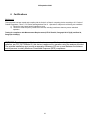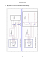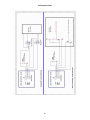
1
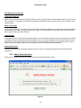
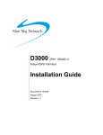
USER MANUAL
Ctek Z Series Router
Model Z4300
Ctek – Things That Move Data
.
22 September 2009
Table of Contents
TABLE OF CONTENTS
I PREFACE
1 1 INTRODUCTION
1 1.1 Theory Of Operation
1 1.2 Features
1 2 CONNECTORS, LIGHTS, SWITCHES, AND JUMPERS
3 2.1 Switches
3 2.2 Lights
3 2.3 Connectors
4 3 START UP
5 3.1 Power
6 3.2 Connecting the Antenna
6 3.3 Connecting to the Ethernet Port – Administrative Connection
6 4 ADMINISTRATION, CONFIGURATION AND STATUS
6 4.1 7 Getting Started
4.2 Interfaces
4.2.1 Configuring The Wireless Interface
4.2.2 Configuring The Ethernet Interace
4.2.1 The RS232 Interface
4.2.2 Configuring The Relay Input Interface
4.2.3 Configuring The Relay Output (Driver) Interface
8 8 11 13 14 15 4.1 Status
4.1.1 Wireless Status
4.1.2 View All Networks
4.1.3 Ethernet Status
16 16 18 19 4.2 Services
4.2.1 Password Administration
4.2.2 Routing and Forwarding Services
4.2.3 TCP PAD Services
4.2.4 UDP PAD Services
20 20 20 23 28 i
22 September 2009
4.2.5 4.2.6 29 30 Admin Screen Services
SIM Management Tools
4.3 Options
4.3.1 Applications
4.3.2 Tools
31 31 31 5 SPECIFICATIONS
31 6 CERTIFICATIONS
33 7 APPENDIX A – DISCRETE I/O ELECTRICAL DRAWINGS
34 ii
22 September 2009
Preface
Welcome to the Ctek Z4300 Router User’s Guide. The Z4300 is an EDGE model with GPRS fallback. The configuration
and administration of the 4300 model is identical to previous generations of SkyRouters with the exception of a few small
differences noted in the text. The User’s Guide will explain the basic operation of the routers and take you through the
necessary settings to get your wireless application online. Additional information and applicable technical notices can be
found at www.ctekproducts.com.
1 Introduction
Wireless routers provide application and network designers with a bridge between the world of IT infrastructure and the
evolving wireless data networks. With the Z Series the wireless transport is fully integrated into the product’s routing fabric
meaning that you can approach the setup and operation of this product much as with any other IP addressable device.
Wireless considerations are reduced to the absolute minimum necessary to register and make connections on a network.
1.1
Theory Of Operation
The Z Series router is a complete IP router that routes traffic over LAN Ethernet (10/100baseT) connections. The wireless
features of the router simply extend the IP routing capabilities to include routing and network address translation (NAT)
over GSM EDGE wireless networks. A fallback GPRS transport is also provided. As with most routers Ctek’s Z Series can
be viewed as having a Local Area Network (LAN) side and a Wide Area Network (WAN) side. Traffic originating at the
router’s Ethernet or Serial port is considered LAN traffic. The Wide Area Network connection is over the wireless
network’s EDGE/PRS transport.
1.2
Features
This manual covers Ctek Z4300 and contains the following feature and functions.
1) Ethernet
a. Static Addressing
b. Dynamic (DHCP) Server
c. DHCP Client
d. Configurable DNS address
e. Configurable Gateway, Sub net mask, and Broadcast address
f. Port Forwarding
g. Service management
2) EDGE/GPRS Interface
a. Enable/Disable Wireless Routing
b. Enable/Disable inbound IP requests
c. Name Server Interoperability with UDP or SMS
d. DDNS Interoperability with BIND or MS Server
e. Administration web server port address selection
f. Home Network Selection
3) RS232
a.
b.
c.
d.
Configurable Bit Rate
Configurable for Start/Stop Bits, Flow Control, and Parity
Local and remote Telnet Access
Enhanced Packet Assembly and Disassembly (PAD) function.
1
22 September 2009
4) USB Host – Z4300U Model Only
5) Relay Contact Closure (detection and operation)
a. NO/NC detection
b. SMS or email cry out alarm
6) Relay Driver Output
a. SMS Activation
b. Web Activation
7) General Administration
a. Modify Password
8) Status – Ethernet Status
a. Currently Assigned IP Address
b. Current MAC Address
9) Status – EDGE/GPRS Status
a. IMEI – Equipment ID
b. Network Assigned IP Address
c. Telephone Number (MSISDN)
d. Current Network Status Active/Inactive
e. Signal Level (RSSI)
2
22 September 2009
2 Connectors, Lights, Switches, and Jumpers
2.1
Switches
Referring to Figure 1, there are two switches on the front of the Z Series router. S1 (Reset) causes a hard reset of unit.
S2 (DFLT) is used to completely restore the firmware settings that were included when the product was shipped from the
factory. To restore factory defaults, the unit must be running. Press the Restore Defaults (inner) switch and hold it down
for 10 seconds. After 10 seconds, you will see both the green and yellow lights go off. At that time you may either press
the reset (outer) switch or cycle power on the unit.
Reset Default
LINK SERVICE LAN
Figure 1
2.2
Lights
The Z Series router has indicators as shown in Figure 1.
LAN – The LAN light indicates that the Ethernet port is connected to an active Ethernet device.
The network status indicators LINK and SVC are interpreted as follows:
SVC – Multi-color (yellow/green). Indicates:
a) Power
b) RSSI
Display
Definition
Off
Yellow Blinking
Yellow Solid
Green Solid
No Power
Power On – No Signal (RSSI)
Power On – RSSI < -88
Power On – RSSI >= -88
3
22 September 2009
Link - Multi-color (red/green). Indicates:
a) Status of IP connection
b) Type of transport (EDGE or GPRS)
2.3
Display
Definition
Off
Green
Red
No Connection (IP address)
Connection established on GPRS
Connection established on EDGE
Connectors
RS232 Connector – This connector is a standard RS232 DCE interface. A straight-through RS232 cable should be used.
The RS232 connector pin out diagram is shown below.
Figure 2
Ethernet Connector
The Ethernet connector on the Z Series is a standard RJ45 connector with auto polarity sensing and can be used with
either a standard Ethernet cable or a reverse (cross over) Ethernet cable.
Terminal Block
Connector J1 supports four separate functions, power, relay contact closure detection, relay driver output, and auxiliary
serial port serial data. Contact closure pins 2 and 4 are shared with the auxiliary serial port. To option remove the circuit
board and locate 3-pin headers JP1 & JP2 behind the green connector. Facing the end of the board containing the green
connector JP1 and JP2 should have jumpers center to right to use the discrete I/O (Din, Dout), and JP1 and JP2 should
have jumpers center to left to use the auxiliary serial port. Auxiliary serial port parameters (baud, parity, etc.) are set using
the RS232 screen. From the factory the unit ships with the auxiliary serial port enabled.
.
The pin out configuration is as follows:
4
22 September 2009
Terminal Block Pin
JP1 & JP2 (internal) Center to Right
Pin 1
Pin 2
Pin 3
Pin 4
Pin 5
Pin 6
Din – Discrete Input (See Appendix A)
Din Src – Discrete Input Source
Dout Gnd – Discrete Output Ground
Dout - Discrete Output
Power supply Ground
Power supply +12VDC
JP1 & JP2 (internal) Center to Left
RxD of auxiliary serial port
Ground of auxiliary serial port
TxD of auxiliary serial port
Power supply Ground
Power supply +12VDC
Figure 3 – Z4300S Model
Figure 4 – Z4300U Model
3 Start Up
Warning – You must connect antenna(s) to the SMA style antenna connectors on the router before turning it on.
Failure to do this could result in erratic start up behavior and could possibly damage the unit.
Note – Z Series routers ship from the factory with DHCP server enabled. The Default Gateway address for the
unit is 192.168.1.10. The address of the web based administration is also 192.168.1.10. After you have activated
your unit on the wireless network it WILL NOT have a DNS address, meaning that public Internet web access will
not work. To load DNS values go to the Ethernet Interface screen, select “Acquire From Wireless Network” and
press the update button. At this point the Primary and Secondary DNS addresses in the Ethernet Interface screen
will be populated with the DNS addresses provided by your wireless network. As a last step restart both the
router and the connected PC.
5
22 September 2009
3.1
Power
Before starting connect the supplied 12VDC power adapter to the power connector described in Section 2. The adapter
supplied with your router is suitable for use with 120VAC 60-hertz wall power. If you need a different power solutions
contact Ctek.
3.2
Connecting the Antenna
Antennas should be attached to the SMA style antenna connectors described in section 3. The antenna must be
connected before powering the unit on.
3.3
Connecting to the Ethernet Port – Administrative Connection
For a direct Ethernet connection between a PC connect to the Ethernet port using a standard or reverse Ethernet cable.
For initial configuration and administration with a PC or workstation Ctek recommends that the PC be set to obtain an IP
address and obtain a DNS address automatically. For Windows PCs make the following settings under the networking
control panel
Figure 5
4 Administration, Configuration and Status
About Addressing – Devices connecting to GSM/EDGE/GPRS networks are assigned an IP address by the serving
network. Address assignment may either be static or the unit will be dynamically assigned an IP address, depending on
arrangements that you have made with your wireless network operator. Dynamically assigned IP address remain in effect
for a period of time assigned by the network operator, usually at most a small number of hours.
Ctek’s Z Series includes features that manage the temporal nature of dynamically assigned wireless IP addresses. Using
the Wireless Configuration screen you can configure your router to use a Dynamic DNS (DDNS) service. Ctek operates a
DDNS test bed that allows our customers to observe the performance and reliability of DDNS with their applications. For
large-scale commercial applications Ctek recommends that users configure their own DDNS, managed and maintained
with the customers ongoing IT operations. The Z Series may also be configured to operate with a standard DNS having
Dynamic DNS capabilities. Examples of this type of service would be Berkeley Internet Name Daemon (BIND) and Microsoft
Server 2000 and up. For detailed information see Ctek’s TechNote S001.
6
22 September 2009
Even if you elect to use a static IP address a DDNS service will add value in two ways. First, when the networks static
addressing assignment fails there is a mandatory waiting period before the endpoint is allowed to reinitiate the request for
a static address registration. During this period of time the network will dynamically assign addresses to the end point. A
DDNS service will make the end point network addressable (by name) during this period of time. Secondly, a name
service allows your end point to be known by a name that is independent of network addressing. Addressing a unit by
name may be easier for end users to remember and will, over a long period of time, reduce maintenance problems.
4.1
Getting Started
Once the PC has been set up properly and physically connected to the router you are ready to begin configuring the
router for your application. To access the Administration menu use a conventional web browser pointed at http://
192.168.1.10. A login screen appears as shown below. The default User ID is “ctek” (without the quotes) and the default
Password is also “ctek”. Be sure to change the user ID and password and record your new selections.
Figure 6
When you have completed the login process you will be presented with the top-level administration menu.
7
22 September 2009
Figure 7
Note that the administration menu is divided into four sections. The Interfaces section deals with physical connectivity,
managing the connection and subtended devices. Status screens are provided for the EGPRS/GPRS and Ethernet
interfaces. Services are applications that are within the router core to modify the behavior of a specific interface or to
change system wide parameters within the router core. Under the Options category users can find any optional or custom
applications and tools provided to maintain the router.
Important Note – The Restart button must be used to apply any changes made on specific Interface
or Service screens.
4.2
Interfaces
4.2.1 Configuring The Wireless Interface
The configuration screen for the wireless interface is shown below. The actual wireless interface is provisioned and
configured by the wireless Network Operator. The router’s Wireless Interface Configuration screen is used to establish
select from those capabilities available such as inactivity timeouts and Name Server selections.
8
22 September 2009
Figure 8
Network Select – Available settings are Automatic, Prefer A Network, or Demand a Network.
Automatic – Allow radio to select network based on SIM and signal quality
Prefer a Network – Similar to Automatic with a bias towards the network ID specified in the Network ID field
Demand a Network – Make every effort to use the network specified in the Network ID field
User Name and Password – Normally blank. Required for activation on some networks. See TechNotes for specific
usage.
Wireless Connection – Used to enable/disable the wireless WAN connection.
Disabled – Turn off WAN connection
Enabled – Turn off WAN connection
Inactivity Timer – Used to specify a duration of no outbound or incoming traffic after which the WWAN connection will be
re-established.
APN – Provided by the network operator. Determines what IP addresses are assigned to the mobile station, what security
methods are used, and how the GSM data network connects to the customer’s network.
9
22 September 2009
PDP Address – Provided by the network operator. Specifies the address of a particular device’s Packet Data Protocol
context area in the network.
Authentication – Available settings are None, PAP, CHAP, BOTH. Usually set to none but may be required on some
networks.
Enable LCP echo packets – Used on some International networks. For all US networks LCP echo packets should be
turned off, meaning this box should be unchecked. If you have questions check with Ctek support.
SMSC Address – Short Message Service Center Address. A number prefixed with a plus (+) sign that specifies the
service center that will handle SMS traffic. Provided by the network operator.
Email Gateway – A number (address) specifying a gateway that will transform email to SMS and SMS to email. Provided
by the network operator. Note that emails targeted at SMS delivery have network dependent formats.
Select DNS Type – Used to select the appropriate protocol for your Dynamic DNS.
1)
2)
3)
4)
None – DDNS will not be used.
EW/SMS – Use Ctek Enhanced Wireless DDNS with SMS updates. Not currently supported.
EW/UDP - Use Ctek Enhanced Wireless DDNS with UDP updates over the GPRS/EDGE Air Interface
Standard UDP – Use a standard BIND, MS2000, or MS2003 DDNS server
Device Name – Establishes the name by which this particular router will be known at the Name Server. This entry must
be a fully qualified device name and domain and is limited to 40 characters in total. It is limited to one level of name space
definition meaning that all characters to the right of the first “dot” will be assumed to be a component of the resolving
server. An example would be ctek01.thingme.net where ctek01 is the name of an individual router and thingme.net is the
name of the resolving server.
Primary and Secondary Name Server – Enter the IP address of the designated Name Server. Name resolution is not
performed on this entry meaning that a numeric IP address of the resolving server is required.
Provide Network Name Server Facilities – Selecting Yes causes this router to provide Name Server services to client
Ctek routers configured to use it. If this option is selected additional set up in the Name Services screen will be required.
10
22 September 2009
4.2.2 Configuring The Ethernet Interace
The Ethernet configuration determines how devices connected to the LAN side of router will be addressed, and what the
actual address of this router will be on the LAN.
Figure 9
Media Type – Determines the type of Ethernet connection. Auto allows router to determine what the connection is. This
setting is appropriate for most cases. Other settings are to select either 10Mb (10baseT), 100Mb (100baseT), Full Duplex
(FD), or Half Duplex (HD). Again, in almost all cases Auto will correctly determine the proper setting.
DHCP Configuration – These settings determine the network topology of the LAN side of router’s network.
Disabled – You must manually configure the IP address and other addressing parameters described in the next
section . It is recommended that the router be assigned a private static address of 192.168.1.10.
Enable Server - This router must be assigned a private static IP address, as defined in the next section. It is
recommended that an address of 192.168.1.10 be used. The DHCP server will issue dynamic IP addresses to
other devices connected to the LAN side. IP addresses will be assigned for up to 50 devices. Address assignment
is sequential in the range of 192.168.1.100 – 192.168.1.150.
11
22 September 2009
Enable Client – Some other device on the LAN side of the network is acting as a DHCP server. The router will be
assigned a dynamic IP address by the DHCP server.
DNS Address Source – In most cases this parameter should be set to Acquire From Wireless Network. In this case,
when you click on the Update button, the router will verify that it has been connected to the wireless network and that the
wireless network has provided DNS addresses. If DNS addresses have been provided, they will be displayed in the
Primary and Secondary Address boxes. If addresses have not been provided, you will receive an error indication. At that
point, you should allow the router to establish a connection with the wireless network so that it can acquire the DNS
addresses. You should then go back into the Ethernet Configuration screen and click on submit again. At this point, the
DNS addresses should appear.
If you application requires a specific DNS setting check the User Defined box and manually fill in the DNS IP Address
fields below.
DNS IP Address (Primary and Secondary) – The address of the Domain Name Server that your network uses. This
should not be confused with the Name Server entries on the Wireless Interface screen. The DNS referenced by these
addresses will resolve outbound queries.
IP Address – The IP address assigned to the LAN segment of this router.
NetMask – This parameter is also known as Subnet Mask. Network Mask determines which portion of an IP address is
the network portion and which portion belongs to the host. As an example a setting of 255.255.255.0 would indicate that
the first three groups of this address (255.255.255) identify the network and that the last group (000 – 254) identify a
particular host.
Default Gateway – The Default Gateway is the address of a device that the router will use to reach remote networks or
servers. In many cases this will be a firewall address. In a normal situation where the Z4300 is acting as a fringe router
and is expected to pass incoming Ethernet traffic through to the network, this field should be left blank. If the router is
acting as a RAS where traffic is coming in from the network so that it can be routed through to some sort of host/server,
this field must set to an address on the Z4300’s LAN segment.
Broadcast Address
If applications on the router need to do a broadcast operation, this is the address that will be used on the Ethernet
segment to fulfill the broadcast request.
12
22 September 2009
4.2.1 The RS232 Interface
This screen sets basic parameters for the RS232 port and the auxiliary serial port. These settings should be made to
correspond to those on the far end of the serial connection or serial over IP emulation. The RS232 serial port is available
for al applications and can be connected to the TCP or UDB PAD feature. The auxiliary port is available for selected
applications.
Figure 10
Bit Rate – Selects transmit and receive speed. This setting is available on both the serial and auxiliary ports.
Character Length – Selects the number of bits representing a character. This setting is available on both the serial and
auxiliary ports.
Parity – Selects the parity bit setting that will match the far end. This setting is available on both the serial and auxiliary
ports.
13
22 September 2009
Flow Control – Selects No flow control, Hardware Flow Control (RTS/CTS), or Software Flow Control (XON/XOFF). If
RTS/CTS is selected make sure that the cable you are using has those pins connected on both ends. Many premanufactured cables either do not terminate these signals or else jumper them into a permanent True state.
Service – determines the mode of operation for the RS232 port.
None - Indicates that a custom application and protocol has been implemented.
TCP PAD - Selects the Packet Assembly and Disassembly Service.
4.2.2 Configuring The Relay Input Interface
This screen configures the connection characteristics of the relay input interface and defines the service associated with
this interface. Currently, the relay interface can cause an SMS message to be sent to another wireless device or an email message to be sent to any valid email address.
Appendix A contains schematic information concerning the relay input configuration.
Figure 11
Relay Input Trigger – Establishes the conditions under which the Relay Service will be invoked. Unless it is disabled the
relay input is sampled at 1000 millisecond (1 second) intervals.
Disabled – Never respond to relay activity
On Closure – Respond when relay contacts go closed
On Opening - Respond when relay contacts go open
14
22 September 2009
Maximum Trigger Rate – This setting determines how often the router will send a “relay event” message. If the relay
event is recurring at a rapid rate this setting will prevent an undesirable “flood” of messages. If Maximum Trigger Rate is
set to "Always" the relay input is operating in edge triggered mode. In this mode the router will invoke its assigned
service any time that the input transitions to the selected state. So if ON CLOSURE is selected an SMS is sent every time
that the contacts close. This means that once closure is sensed there can be no other closure event until the contacts are
first sensed to be open.
All other modes where Max Trigger Rate has a time value are level sensitive. So if the contacts close an SMS is sent and
then the state of the relay input is ignored for a defined period of time. For instance, if Max Trigger Rate is set to 5
minutes an SMS is sent and then the relay input is sampled again in 5 minutes. If the contacts are still closed another
SMS is sent. If the relay input is not closed the router reverts to monitoring the relay every second.
SMS Destination Address – The MIN (mobile phone number) or email address to which the SMS message will be sent.
MIN must be 10 numeric characters with no spaces or punctuation. Any email address in the form
Anything@Any_Domain will be accepted.
SMS Alert Message – The text of the message to be sent when the relay interface activates. Limited to 100 characters
maximum. Only printable ASCII characters in the range of 32 – 126 decimal (20 – 7E hex) can be included in the
message.
4.2.3 Configuring The Relay Output (Driver) Interface
This screen configures the connection characteristics of the relay output interface and defines the service associated with
this interface. Currently, the relay output interface can be activated by an SMS message or from a button that can be
defined on the Advertising screen described in the Services section.
Appendix A contains schematic information concerning the relay output configuration.
Figure 12
15
22 September 2009
Set Relay Output State – Used to set the current state of the relay driver circuit. The relay driver can be activated and
deactivated by changing this setting and pressing update.
Relay Shut Off Timer – The relay driver circuit will revert to its default setting after the number of minutes or seconds
specified by this parameter. The two second setting is useful for resetting end point equipment.
Allow SMS Control of Relay – If Yes is checked the relay driver may be activated by sending an SMS with the command
“R1” and deactivated by sending an SMS with the command of “R0”.
Allow Web Browser Control of Relay – If set to yes a button will appear on the Advertising screen to enable and disable
the relay driver circuit.
Text For Web Link To Relay – This text will appear on the advertising screen next to the relay activation button.
4.1
Status
4.1.1 Wireless Status
The Wireless Status interface provides information on the Z4300 Series router’s wireless network connection, local
operating conditions, and predefined information contained within the radio module. Wireless status information can be
refreshed (updated) in real time using the Refresh button at the bottom of the page. The Wireless Status interface is
display only.
Figure 13
16
22 September 2009
Carrier – Often referred to as the Mobile Operator
Network Status – Possible values are “In Service”, “No Service”, or “Service Denied”. Indicates the state of the network
as seen through your particular router
Service Type – Indicates whether EGPRS (EDGE) is available or failing that whether GPRS is available. Possible values
are “None”, “EGPRS”, or “GPRS”.
Current IP Address – The Internet Protocol (IP) address assigned to this router by the serving wireless network. If this
field is blank a connection does not currently exist.
Signal Level (RSSI) – A measure of the strength of the wireless signal that your router is currently seeing. A larger
negative number indicates a marginal network connection. Typically this number will be in the range of -75 - -95dBm
although there are many locations where the value will be outside of the typical range.
Roam Status – Indicates the network’s view of the current geographic location of your router. The possible values are
“Not Roaming”, or “Roaming”. An indication of Roaming may or may not impact your data transmission costs. Charges
are a function of your rate plan, not necessarily linked to the networks notion of roaming.
Call Status – Indicates the current status of network registration. Possible values are “Attached”, or “Not Attached”.
Subscriber ID (IMSI) – Identifies the subscriber. IMSI is contained in the SIM.
Equipment ID (IMEI) – Identifies a particular piece of hardware, specifically the radio within the SkyRouter
Radio Type – Displays the Radio Manufacturer
Firmware Rev. – Displays the firmware revision level of the radio.
Phone Number (MSISDN) – The network address of the unit
Short Message Service Center Address. - A number prefixed with a plus (+) sign that specifies the service center that
will handle SMS traffic. Provided by the network operator.
Model – The model number of the radio installed.
Hardware Rev. – If available displays the revision level of the radio module
17
22 September 2009
4.1.2 View All Networks
The View All Available Networks button at the bottom of the wireless status screen will display all networks seen by the
SkyRouter in an expanded wireless status screen. The network IDs displayed in this function can be used in the Wireless
Interface function to constrain a unit to a specific network.
Figure 14
18
22 September 2009
4.1.3 Ethernet Status
Indicates the current LAN side IP address that the router is using. MAC Address is a vendor and machine specific
identification code.
Figure 15
19
22 September 2009
4.2
Services
4.2.1 Password Administration
Used to change passwords and create users. Be sure to record this information in a secure location.
Figure 16
4.2.2 Routing and Forwarding Services
The Routing and Forwarding Services screen provides two separate but related functions. First it allows you to forward
WAN side IP traffic arriving on a specific IP Port to a specific Port at a LAN side address. In addition to this conventional
forwarding feature this screen also allows you to make a Named Service publicly available over the WAN interface. In
Figure 17 below WAN side UDP and TCP traffic arriving on Port 88 is redirected to Port 80 of LAN address
192.168.1.102.
The second function performed by this set up screen to allow named services to be made publicly available to WAN side
users. Referring again to Figure 17 a service named “Ctek SkyRouter Demo – San Pedro, CA” will be advertised or made
publicly available. Security for this advertised service is left up to the specific service. If the Advertising feature is used the
Administrative Login screen will no longer greet incoming WAN users, instead they will be presented with a Services
screen as shown in Figure 18.
20
22 September 2009
Figure 17
Block Inbound IP Traffic From Wireless Network – If set to Yes the router’s firewall is configured to block any inbound
originated (but not response) packets from the wireless network (WAN). This firewall is then selectively modified by the
forwarding entries defined through this screen. If this parameter is set to No, the router’s firewall is disabled.
Use NAT on all Ethernet traffic to wireless network – For normal operation this parameter should be set to “Yes”. In
some unique situations, you may connect the router to a network where you will be given public address to use on your
LAN’s Ethernet segment. In such cases, NAT should be turned off. NAT is currently required for operation on all US
networks such as T-Mobile USA or AT&T. Typical environments where NAT would be turned off would be private
networks or some types of VPNs and in these cases, the network operator will most likely provide configuration
assistance.
Forward Inbound Port – This table allows WAN side packets addressed for specific IP ports to be routed to a specified
address on the LAN side.
Of Local Address – Used to specify the LAN side address of the routing operation.
TCP – Route TCP/IP traffic
UDP – Route UDP/IP traffic
Enable – Activate this routing setting
Advertise This Service – Display this named service for WAN users
With Title – The name assigned to this service
21
22 September 2009
Figure 18
22
22 September 2009
4.2.3 TCP PAD Services
TCP PAD OVERVIEW – The TCP PAD was designed to work with any application that would typically use either a dial-up
or leased line modem.
Figure 19
23
22 September 2009
Dial Mode Call Initiation - In dial mode, the PAD offers two standard methods for call initiation:
AT Command Initiated Dialing
DTR Controlled Dialing
Dial Mode Call Answering - In dial mode, the PAD offers two standard methods for call answering:
Auto Answer
AT Command Initiated Answer
Auto Dial (leased line) Mode - In auto dial (leased line) mode, the PAD provides auto-dial and auto-recovery facilities so
that a connection is always available. The PAD may be configured to auto-dial as many as four destinations. If a
connection cannot be established with one destination, the PAD will automatically attempt to connect with other
configured destinations. Auto dial mode may be configured so that is controlled by DTR to implement DTR dialing.
Selective Call Acceptance - In all modes, the TCP PAD may be configured to selectively accept or reject incoming calls. If
this feature is enabled, up to ten incoming IP addresses may be defined as acceptable.
Packet Forming – The TCP PAD accepts characters from the RS-232 interface and assembles them into an outbound
TCP message. The PAD provides a number of data management parameters for controlling the formation and
transmission of the TCP message.
TCP PAD CONTROL SIGNALS
The PAD uses the following RS-232 control signals:
Data Set Ready (DSR) Pin 6 – This output signal, sometimes known as Modem Ready, is controlled by the PAD. When
the PAD begins operating, DSR will be turned on. Please not that this only indicates that the PAD is operating. It does not
indicate that there is a data connection.
Data Carrier Detect (DCD) Pin 1 – This output signal is controlled by the PAD. When a TCP data connection has been
established, this signal will be turned on. When a data connection disconnects, this signal will be turned off.
Ring Indicator (RI) Pin 9 – This output signal is controlled by the PAD. It will toggle at a normal ring cadence if there is an
incoming call and the PAD is configured for an AT Command answer mode.
Data Terminal Ready (DTR) Pin 4 – This is an input signal. The PAD may be configured to either monitor or ignore this
signal. If the signal is being monitored, DTR must be on in order to establish a call. If a call is established and DTR is
turned off, the call will be terminated.
TCP PAD PARAMETER DETAIL – Before configuring the TCP PAD, be sure to review the RS-232 configuration screen
and ensure that you have selected the proper physical characteristics for the RS-232 hardware interface. Also ensure
that you have selected the TCP PAD as the service that will be connected to the RS-232 interface.
Call Setup Parameters
Answer Mode
AT Cmd – PAD accepts ATA command for acceptance of an incoming call.
Auto - Pad will automatically accept an incoming call
Dial Mode
AT Cmd – PAD accepts a variety of ATD command formats for establishment of an outbound call.
24
22 September 2009
Auto – PAD automatically attempts to connect to the destinations defined in the Outbound IP Parameters. The PAD
will start with destination 1 and will continue to sequence through all defined destinations until a connection is
established.
*** NOTE ***: If Auto is selected for Dial Mode, then Answer Mode is effectively disabled since the PAD will be
continuously attempting to establish an outbound connection.
AT Command Response
On – Response and error messages generated
Off – No responses or error messages generated
AT Command Echo
On – All characters echoed in command mode
Off - No echo of command characters
AT Escape Sequence – When the PAD is in data mode, it accepts the standard +++ escape sequence to return to data
mode. In some applications, this is not desirable.
On – Enables the standard +++ escape sequence
Off – Disables the escape sequence
DTR Control
On – Enables call control based on the state of DTR
Off – PAD ignores state of DTR
Local Echo
On – All characters received in both command and data mode will be echoed.
Off – No echo of local characters will be done. Command characters will still be echoed if AT Command Echo is on.
Outbound IP Parameters – The user may define as many as four destinations that will be used by the PAD
Inbound IP Parameters
Listen port number – Defines the port that the PAD will listen on for incoming connections.
Accept calls from all IP addresses or Accept calls from only the following IP addresses – Allows the user to selectively
accept inbound calls based on the source IP address.
Data Management Parameters
Termination Character – The user may define a termination character that will cause any buffered characters to be sent.
In conjunction with the Termination Character parameter, the user may define the length of a block check sequence
(Block Check Length) that follows the termination character. This will ensure that LRC or CRC characters following the
Termination Character are included in the same outbound message.
25
22 September 2009
Transmit Timer – The user may define a timeout value that will cause any buffered characters to be sent.
Maximum Block Size – The user may define a block size threshold that will cause buffered characters to be sent.
Strip Telnet Line Feed – If selected, line feeds following carriage returns will be deleted from inbound and outbound data
streams.
Inactivity Timer – The user may choose to configure the PAD to terminate a connection if no inbound or outbound data
traffic occurs for a defined period of time.
Please note: Any Data Management Parameter may be disabled by setting its value to zero.
TCP PAD COMMAND DETAIL – The following is a summary of supported AT commands. Although all commands are
shown in upper case, this is not a requirement. Commands may be either upper or lower case. Please note that all
unsupported commands will return a standard OK response for compatibility.
Dial Command – The dial command is used to establish a TCP connection. The following is a summary of all supported
forms of the dial command:
In the following cases, both the IP address and port number are provided as parameters:
ATD Address Port
ATDAddress Port
ATDT Address Port
ATDTAddress Port
ATDP Address Port
ATDPAddress Port
In the following cases, the port number is retrieved from default Destination 1 of Outbound IP Parameters:
ATD Address
ATDAddress
ATDT Address
ATDTAddress
ATDP Address
ATDPAddress
In the follwoing cases, the IP address is retrieved from default Destination 1 of Outbound IP Parameters:
ATD Port
ATDPort
ATDT Port
ATDTPort
ATDP Port
ATDPPort
In the following case, both the IP address and port number is retrieved from default Destination 1 of Outbound IP
Parameters:
ATD
In the following cases, both the IP address and port number is retrieved from the specified Destination of Outbound IP
Parameters:
ATDS=1
ATDS=2
ATDS=3
ATDS=4
26
22 September 2009
Hang Up Command – The following command will disconnect a TCP connection:
ATH
Go Back To Online Mode – The following command is used when the user has escaped from data mode to command
mode. By issuing this command, the PAD will be returned to data mode
ATO
Escape sequence – When the PAD is in data mode, an escape sequence can be entered that will cause the PAD to go to
command mode. The main reason for doing this would be to then issue a Hang Up Command. The escape sequence is
the following three characters:
+++
TCP PAD COMMAND RESPONSES – The following is a summary of supported AT command responses. Responses will
always be upper case characters.
Response to a valid command
OK
Response to an invalid command
ERROR
Response when connection is established
CONNECT
Response when connection attempt fails or connection is lost
NO CARRIER
When the PAD is in AT answer mode in there is an incoming call, the following message will be displayed at a normal
ring cadence:
RING
27
22 September 2009
4.2.4 UDP PAD Services
Figure 20
PAD Operational Mode
Outbound IP Parameters.
Inbound IP Parameters
This setting is used to select whether the UDP PAD will operate in client or server mode. In client mode the PAD will
transmit to a server defined by the Outbound IP Parameters. In Server mode the PAD will listen for UDP traffic on the
Port defined in Inbound IP Parameters. The IP address table found in Inbound IP Parameters allows the user to specify
certain IP addresses that will be listened for. Traffic from all other IP addresses is ignored.
28
22 September 2009
Data Management Parameters
Termination Character
When receiving characters from the RS-232 interface, receipt of this character will cause buffered data to be sent over the
TCP connection. If no character is defined buffered data is transmitted based on maximum block size or character timer
(defined below).
Block check length
In many cases, there are 1 or 2 bytes of CRC or LRC after a termination character is received and it is usually desirable to
have those bytes included in the same packet with the data. This field allows the PAD to buffer those block check bytes
before acting on the termination character.
Transmit timer
In the case where the router has buffered transmit data, has not reached the maximum block size, and has not received a
termination character, it will transmit the buffered data if it does not receive a character from the RS-232 interface in this
period of time. For instance, if this timer is set to 200msc, every time another character is received this timer is reset to
200msc. If the timer expires before the next character is received all buffered data is transmitted.
Maximum Block Size
If router receives this many characters without a timeout or without a termination character the buffered data will be
transmitted.
4.2.5 Admin Screen Services
This service allows the user to control overall local and remote administrative access.
Figure 21
29
22 September 2009
Port Number For Admin Screen Access – Causes the WAN side web server to listen on a port other than the default of
Port 80.
Allow Network Access To Admin Screens – If set to Yes administrative users will be able to connect to router’s Admin
interface over the wireless network connection. If this selection is set to No only local administration is possible.
4.2.6 SIM Management Tools
In M2M deployments it is common to receive SIM cards that do not have an MSISDN assigned (burned in). The SIM will
work find but this may prove to be an annoyance for field personnel. The SIM Management Tool will allow you to program
the MSISDN into your SIM card.
Figure 22
30
22 September 2009
4.3
Options
4.3.1 Applications
The Z Series router is capable of installing and managing custom applications. The Applications Services screen is the
user interface to manage custom applications. The individual application release documentation will document the
individual applications behavior.
Figure 23
4.3.2 Tools
The Tools category offers a limited subset of the TCOPlus feature group. Currently the Over-The-Air Firmware update
mechanism is provided.
The entire TCOPlus feature group is available as a purchase option for the Z Series models. For details refer to Ctek
Application Programming Note APN001.
5 Specifications
Controller
Axis Etrax 100LX MCM 4+16
Linux 2.6
Interfaces
Ethernet - RJ45 Ethernet 10/100baseT Full or Half Duplex auto polarity sensing
RS232 – 9 pin D type RS232 serial interface
Relay Input Interface - Designed to detect closure or opening of relay contacts.
Physical – 2 Pin Terminal Block
See Appendix A for details
Relay Output Interface
Physical – 2 Pin Terminal Block
See Appendix A for details
31
22 September 2009
Wireless Interface
Class 12 EGPRS (EDGE) with Class 12 GPRS fall back
Physical – SMA Antenna (removable)
.FCC: Part 22, 24 and 15.
Power Requirements
Standard – 9 - 18VDC
115VAC -> 12VDC Wall Transformer included.
Power Consumption @12VDC nominal
Dormant – Ethernet Connected 106ma
Transmitting – Ethernet Connected – 160ma
Environmental
Operating and storage temperature range: - 30C to +70C. Humidity: 90% non-condensing.
Physical
Dimensions Z4300S: 4.5"L x 5.3"W x 1.2"H. Weight: 10oz.
Dimensions Z4300U: 5.25"L x 5.3"W x 1.2"H. Weight: 12oz.
Mounting – Self standing or wall mount
32
22 September 2009
6 Certifications
FCC Part 15
This equipment has been tested and complies with the limits for a Class A computing device according to U.S. Code of
Federal Regulations, Title 47, FCC Rules and Regulations Part 15. Operation is subject to the following two conditions:
1) This device may cause harmful interference, and
2) This device must accept any interference received, including interference that may cause undesired
operation.
Testing for compliance with Measurement Requirements (CFR 47 Part 22, Paragraph 22.917(b)(2) and Part 24,
Paragraph 24.238(a))
WARNING: To reduce any possible hazard due to exposure of the human body to electromagnetic
radiation, per FCC OET Bulletin 65, this device is approved for operation using the antenna provided.
The antenna installation must provide a separation distance of 20 cm or more between the antenna
and all persons to satisfy Maximum Permissible Exposure (MPE) compliance.
33
22 September 2009
7 Appendix A – Discrete I/O Electrical Drawings
34
22 September 2009
35
22 September 2009
36