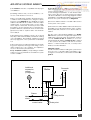
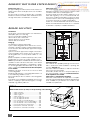
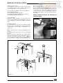
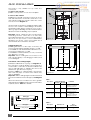
1
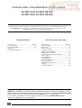
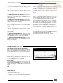
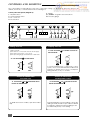
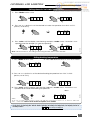
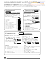
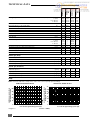
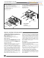
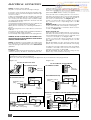
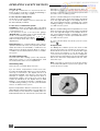
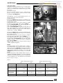
Heating and hot water for the professionals
ECOSY
ECOSY 24 E, ECOSY 5B 24 E is CAT
II2H3+ appliances
IN WARRANTY
TECHNICAL HELPLINE
01773 828400
ECOSY 28 E, ECOSY 5B 28 E is CAT
I2H appliances
01773 828100
1
INSTALLATION AND OPERATING INSTRUCTIONS
ECOSY 24 E, ECOSY SB 24 E
ECOSY 28 E, ECOSY SB 28 E
Note!
The boiler serial number is marked on the label attached to the top of the inner bulkhead. Refer to
the 'Introduction' section page 3 for a description of the basic functions of the boiler. The 'Users'
section describes how to safely operate the boiler.
USERS SECTION
Introduction .................................................. Page 3
Commissioning ....................................................... 3
Controls & lighting ............................................ 4 - 6
Draining ................................................................... 7
Servicing/maintenance ........................................ 7
INSTALLATION SECTION
Introduction ................................................. Page 3
Technical data ...................................................... 8
Dimensions ............................................................. 9
Boiler schematic ................................................... 9
Connections plate .............................................. 10
Piping system installation ................................... 10
Heating system design ....................................... 11
Domestic hot water system design .................. 12
Boiler location ..................................................... 12
Boiler installation ................................................. 13
Flue installation ............................................. 14 - 15
Electrical installation ........................................... 16
Commissioning .................................................... 17
Operating safety devices .................................. 18
Settings ................................................................. 19
Changing gas type ............................................ 20
Mandatory warning for CEE countries
Warning: This appliance is designed, approved and inspected to meet the requirements of the
English market. The identification plate located on the inside of the appliance certifies the origin
where the product was manufactured and the country for which it is intended.
If you see any exception to this rule, please contact your nearest Saunier Duval dealer.
Thank you in advance for your assistance.
2
INTRODUCTION
The ECOSY 24 E and ECOSY 28 E boilers are wall
mounted combination boilers providing central
heating and instantaneous hot water.
The ECOSY SB 24 E and ECOSY SB 28 E boilers are
wall mounted system boiler providing central
heating only.
The ECOSY 24 E and ECOSY SB 24 E boilers are of the
II2H3+ category for use with Natural Gas (G20) and
Liquide gas (G30 and G31)as distributed in the
United Kingdom.
The ECOSY 28 E and ECOSY SB 28 E boilers are of the
I2H category for use with Natural Gas (G20) as
distributed in the United Kingdom.
The boilers have a fan assisted balanced flue which
both discharges the products of combustion to and
draws the combustion air from the outside of the
room.
The boilers are suitable for top outlet flue connection
only but, can be fitted with horizontal flue, vertical
flue or twin-pipe flue. Refer to flue catalogue for
further details.
On ECOSY 24 E and ECOSY 28 E, both the central
heating and domestic hot water temperature are
user adjustable from the boiler control panel.
On the ECOSY 24 E and ECOSY 28 E, domestic hot
water demand always has priority over heating
demand.
The boiler is designed for use as part of a sealed
water central heating system with fully pumped
circulation. The pump, expansion vessel and
associated safety devices are all fitted within the
boiler.
The boiler can be installed against either an external
wall or on an adjacent inside wall, that is, the flue
system will pass directly to the rear or to either side
to the terminal fitted on the outside wall face.
The installation must be carried out by a competent
person in accordance with the relevant
requirements of The Building Regulations, The Water
Byelaws, The Building Standards (Scotland)
Regulations and any applicable local regulations.
These instructions should be carefully followed for
the safe and economical use of your boiler.
Ancillary equipment
A range of flue accessories are available including
vertical flues, twin-pipe flues, bends etc.
For further information contact your supplier.
On ECOSY SB 24 E and ECOSY SB 28 E, the central
heating temperature is user adjustable from the
boiler control panel.
COMMISSIONING
Gas safety (Installation and use) Regulations
In your interests and that of gas safety, it is the law
that ALL gas appliances are installed and serviced
by a competent person in accordance with the
above regulations.
Diagram. 1
OPENING THE CONTROL PANEL COVER
Ins 048a
Gas leak or fault
If a gas leak or fault exists or is suspected, turn the
boiler off and consult the local gas supply company
or your installation/service company.
Boiler controls
The control panel, located at the lower front of the
boiler casing, see diagram 1, allows the boiler to be
started, shut down, controlled and monitored during use.
Flue
Do not obstruct the outside terminal of the boiler.
Starting the boiler
Before starting the boiler check that:
- The gas meter tap is open.
- The boiler gas service cock is open.
- The boiler is connected to the electrical supply and
turned on.
3
CONTROLS AND LIGHTING
The control panel, located at the lower front of the boiler casing, see diagram 2, allows the boiler to be
started, shut down, controlled and monitored during use.
Control panel description (diagram 2):
1 - ON/OFF switch
2 - Summer/winter switch
3 - PC connector
4 - Reset button
5 - Display
6, 7, 8 and 9 - Program selection buttons
10 - Pressure gauge
Diagram 2
1
2
3
4
5
6 7 8
9
10
2
bAR
1
65
IMIT
PC
SET
ENTER
Stopping the boiler
Make sure that:
● The boiler is connected to the electrical supply.
● The boiler gas service cock is open.
● The pressure gauge reads between 1 and 2 bar.
➜
MODE
➜
PUSH IN BUTTON 2 IN SUMMER POSITION TO
STOP THE BOILER
➜
Starting the boiler
PUSH IN BUTTON 1 TO START BOILER
ON
➜
ON
OFF
➜
PUSH BUTTON 2 TO
POSITION TO SET THE
BOILER TO SUMMER MODE
OFF
To ensure maximum life of the boiler control
system, it is recommended that the mains is left
switched on all the time. Power consumption
during stand by is only 7 to 8 watts.
SETTING TO WINTER MODE
(heating and hot water)
SETTING TO SUMMER MODE
(Hot water only)
➜
PUSH BUTTON 2 TO
BOILER TO WINTER MODE
POSITION TO SET THE
➜
➜
ON
OFF
To obtain domestic hot water, open a hot water
tap.
4
3
4
Hab 197a
0
O
ON
OFF
Assuming that any remote heating controls are
calling for heat, the above procedure is all that
is required to start the boiler in heating mode.
Hot water has priority over heating.
CONTROLS AND LIGHTING
Setting domestic hot water temperature
1 - Press «Mode» button once
➭ 1.
65
set
➭ 2.
65
➜
mode
2 - Press «+» or «-» button to set the desired hot water temperature from 40°C to 65°C
(factory set at 65°C)
2. 6 0
➭
-
+
➭ 2.
60
set
➭ 1.
65
twice
Hab 198a
enter
➜
3 - Press «enter» until the display starts flashing, and press «mode» twice : the boiler is now
operational at the desired hot water temperature.
Note : On the SB versions, this setting is done using the tank thermostat in the tank.
Setting heating temperature
1 - Press «Mode» button once
➭ 1.
-
2 - Press «Set» button 4 times to show 5 on the left
60
mode
3 - Press «+» or «-» button to set the desired heating temperature from 20°C to 90°C
(factory set at 70°C)
mode
➭ 1.
65
set
➭ 6.
70
4 - Press «enter» until the display starts flashing, and press «mode» twice : the boiler is now
operational at the desired heating temperature.
twice
-
➭
6. 8 5
Hab 198a
+
Note :
1/ In case of under floor heating systems, the CH flow temperature can be set to between 20 ° C and
45°C - contact the Saunier Duval Technical Helpline 01773 828400.
In all cases, by pressing the «Mode» button until the decimal point disappears, the display reverts to
normal position :
0 65
No decimal point displayed
5
BOILER OPERATING MODES AND DISPLAY READINGS
The Ecosy display has three display modes :
A - Reading mode only - this gives information about the operation in progress.
B - Programming mode - this allows the user to change selected settings of the boiler.
C - Diagnostic mode - this allows the user to check selected temperatures during boiler operation.
A- Reading mode only
70
Flashing decimal point displayed
No decimal point displayed
Allows the user to check selected temperatures
during boiler operation.
During boiler operation, the display gives information about the operation in progress (left
hand digit) and the temperature of that
operation (right hand digits).
1 - Press «Mode» button twice : The number 1
will be displayed with a flashing decimal point
after it.
Flow temperature
➭ 1.
mode
➜
1 - Safety purge
➜
B - Programming mode
65
65
65
65
65
65
65
65
65
65
➭ 1.
2 - Press «Set» button to select the setting that
you wish to check (see table below).
➭ 3.
set
Hab 206
0
1
2 - Ignition
➜
2
3 - Boiler on - central heating
➜
3
4 - Boiler on - hot water
➜
4
5 - Waiting for closing air pressure switch ➜
5
6 - Boiler off after reaching temp.
➜
6
7 - Pump overrun after heating
➜
7
8 - Pump overrun after hot water
➜
8
9 - Boiler safety shut down
➜
9
0 - No demand
70
50
Reg 025
0 65
➭ 1.
C - Diagnostic mode :
1 - Central heating flow temperature
2 - Central heating return temperature
3 - Cylinder temperature
4 - Not applicable
5 - Not applicable
6 - Not applicable
7 - Calculated temperature set
8 - Temperature rise of central heating flow
9 - Temperature rise of cylinder
7 0 Decimal point displayed
Five settings of the boiler can be changed by
the user.
1 - Press «Mode» button once : The number 1
will be displayed with
a decimal point after
➭
mode
it.
1. 7 0
set
Programme
➭ 3.
00
➭
3. 0 1
4 - Press «Enter» button and then press «Mode»
button twice to exit from the programming
mode into the display mode.
enter
➭ 2.
60
➜
2 - Press «Set» button to select the setting that
you wish to change (see table below).
3 - Press «+» or «-»
button to adjust the settings according to the table below
set
➭ 1.
65
Setting
1 ➜ Domestic hot water temperature ............................... adjustable from 40°C to 65°C (factory set at 65°C)
2 ➜ Domestic hot water comfort level ............................... factory set at 02 - do not adjust
3 ➜ Pump operation ............................................................. 00 = do not use
......................................................................................... 01 = Intermittent pump (factory setting)
......................................................................................... 02 = continuous pump
4 ➜ Heating economy .......................................................... factory set at 02 - do not adjust
5 ➜ Heating flow temperature ............................................ adjustable from 20°C to 90°C (factory set at 70°C)
6
DRAINING
Protection against freezing
If the boiler is to be out of use for any long periods
during severe weather conditions, it is
recommended that the whole system, including the
boiler, be drained to avoid the risk of freezing.
If in doubt, consult your servicing company.
The ECOSY boilers have a built in frost protection
device that protects the boiler from freezing. If the
boiler is to be left and there is a risk of frost, ensure
that the gas and electrical supplies are left
connected and that the ON/OFF switch is left in the
ON position.The frost protection device will switch
the pump when the temperature of the boiler water
falls below 7°C and light the boiler when the
temperature falls below 3°C. When the temperature
reaches 10°C, the boiler stops. The pump will run
again 15 minutes.
Note: This device works irrespective of any room
thermostat setting and only protects the boiler.
Always ensure that adequate frost protection is
given to the entire system where necessary.
Draining and filling
Caution: The boiler is installed as part of a sealed
system which must only be drained and filled by a
competent person.
Heating safety valve
CAUTION: A safety valve with a discharge pipe is
fitted to these boilers.
The valve MUST NOT BE TOUCHED except by a competent person. If the valve discharges at any time,
switch the boiler off and isolate it from the electrical
supply. Contact your installation/service company.
SERVICING/MAINTENANCE
To ensure the continued efficient and safe operation of the boiler, it is recommended that it is
checked and serviced at regular intervals. The frequency of servicing will depend upon the installation conditions and usage but, in general, once a
year should be enough.
Cleaning
The boiler casing can be cleaned with a damp cloth
followed by a dry cloth to polish.
Do not use abrasive or solvent cleaners.
Boiler casing
CAUTION. Do not remove or adjust the casing in any
way, as incorrect fitting may result in faulty operation. If in
7
Heating output
Efficiency
Part load efficiency 30% (50°C/30°C)
Maximum heating temperature
Expansion vessel effective capacity
Expansion vessel charge pressure
Maximum system capacity at 75°C
Safety valve, maximum service pressure
Products outlet
Fresh air inlet
Hot water output
Maximum hot water temperature
automatically adjustable from (kW)
to (kW)
from (Btu/H)
to (Btu/H)
(%)
(%)
(°C)
(l)
(bar)
(l)
(bar)
(mm)
(mm)
ECOSY SB
28 E
ECOSY 28 E
ECOSY SB
24 E
ECOSY 24 E
TECHNICAL DATA
6,8
6,8
24,5
24,5
23217 23217
83649 83649
98,9
98,9
109,3 109,3
90
90
7
12
0,5
1
150
215
3
3
Ø 60 Ø 60
Ø 100 Ø 100
8,9
28,8
30386
98330
97,5
106,8
90
7
0,5
150
3
Ø 60
Ø 100
8,9
28,8
30386
98330
97,5
106,8
90
12
1
215
3
Ø 60
Ø 100
automatically variable from (kW)
to (kW)
from (Btu/H)
to (Btu/H)
(°C)
6,8
24
23,21
81,89
65
—
—
—
—
—
8,9
28,8
30386
98330
65
—
—
—
—
—
l/min
(bar)
11,4
8
—
—
13,3
8
—
—
(V)
(W)
230
115
230
115
230
132
230
132
Specific flow rate (for 30°C temperature rise)
Maximum supply pressure
Electrical supply
Maximum absorbed power
Natural gas (G20)
Ø Burner injector
(mm)
4,9
4,9
5,6
5,6
Supply pressure
(mbar)
20
20
20
20
Gas rate (maximum)
(m3/h)
2,6
2,6
3,0
3,0
Gas rate (minimum)
(m3/h)
0,7
0,7
0,9
0,9
(mm)
Liquide gas (G30/G31)
Ø Burner injector
4,15
4,15
/
/
Supply pressure
(mbar)
28
30/37
/
/
Gas rate (maximum)
(m3/h)
0,86
0,86
/
/
Gas rate (minimum)
(m3/h)
0,36
0,36
/
/
Pump :
Note : Curves 1,2 and 3 correspond to each of the three pump speed settings.
ECOSY 24 E, ECOSY SB 24 E
ECOSY 28 E, ECOSY SB 28 E
30
2
20
10
0
1
500
1000
1500
60
50
40
30
20
10
0
flow rate through heating system (l/h)
Diagram 3
8
2
Pom 048
40
Available pressure between
heating flow and return
3
Pom 043 c
Available pressure between
heating flow and return
70
50
(10 kPa = 1 mWG)
500
1000
1500
2000
flow rate through heating system (l/h)
DIMENSIONS
Diagram 4
201,5
227
890 (Ecosy 24 E/SB 24 E)
890
985 (Ecosy 28 E/SB 28 E)
The boiler is delivered in three
separate packages :
- the boiler itself
- the fixing jig
- the flue system
ECOSY 24 E
Net weight : 68 kg
Gross weight : 72 kg
ECOSY SB 24 E
Net weight : 58 kg
Gross weight : 62 kg
Hab 204a
ECOSY SB 28 E
Net weight : 63 kg
Gross weight : 77 kg
140
ECOSY 28 E
Net weight : 73 kg
Gross weight : 87 kg
520
373
BOILER SCHEMATIC
Diagram 5
2
➞
1
17
3
4
5
16
15
6
8
18
7
19
9
14
10
13
11
12
Hab 205
-
➞
Automatic air vent
Air inlet/ flue products outlet
Heat exchanger
Central heating flow thermistor
Burner
Viewing window with ignition electrode
Air pressure switch
Fan
Electronic control box
Gas valve
Condense drain
Pressure gauge
Pump
3-way valve (ECOSY 24 E/28 E only)
Expansion vessel
Cylinder (ECOSY 24 E/28 E only)
Cylinder automatic air vent
(ECOSY 24 E/28 E on&ly)
18 - Central heating return thermistor
19 - Domestic hot water thermistor
(ECOSY 24 E/28 E only)
1
2
3
4
5
6
7
8
9
10
11
12
13
14
15
16
17
9
CONNECTION PLATE
ECOSY SB 24 E, ECOSY SB 28 E
From left to right, the connection plate is equipped with:
A - Heating return with isolating valve (m).
C - Heating flow with isolating valve (q), drain screw (r)
and safety valve (s).
E - Electrical connector.
F - Gas service cock.
ECOSY 24 E, ECOSY 28 E
From left to right, the connection plate is equipped with:
A - Heating return with isolating valve (m).
B - Cold water inlet with isolating valve (p).
C - Heating flow with isolating valve (q), drain screw (r)
and safety valve (s).
D - Domestic hot water outlet.
E - Electrical connector.
F - Gas service cock.
0
1
1
23
3
11
2
m
1
p
5
5
s
25
,5
7
5
m
p
3
A
r
4
B
Diagram 7
E
q
C
Filters and washers :
1 - Fibre washer
2 - Metal filter
3 - Plastic filter
4, 5 & 6 - Black graphite
s
5
6
D
Diagram 6
7
F
Pla 144a
33
2
C
,5
7
5
34
1
q
5
5
3
11
5
Pla 202
r
A
23
5
1
1
25
F
E
PIPING SYSTEM INSTALLATION
Heating system connections - Pipe diam 22 mm
Hot water system connections (ECOSY 24 E/ 28 E
only) - Pipe diam 15 mm
● Gas connection - Pipe diam 22 mm
● Safety valve discharge - Pipe diam 22 mm
●
Water connection
Connect the copper tails and isolating cocks supplied, to the boiler, see diagram 6 or 7. Connect the
system pipework to the boiler observing the correct
flow and return format as shown in diagram 6 or 7.
boiler, the discharge must be extended using not
less than 15 m o.d. pipe, to discharge in a visible
position outside the building, facing downward preferably over a drain. The pipe must have a continuous fall and be routed to a position so that any discharge of water, possibly boiling or steam, cannot
create any danger to persons, damage to property or external electrical components and wiring.
Tighten all pipe connection joints.
Gas connection
The supply from the governed gas meter must be
of adequate size to provide a constant inlet working pressure of 20 mbar (8 in w.g.).
To avoid low gas pressure problems, it is recommended that the gas supply is connected using 22
mm pipe.
● On completion, the gas installation must be tested
using the pressure drop method and purged in accordance with the current issue of BS6891.
●
Safety valve discharge
WARNING. It must not discharge above an entrance
or window or any type of public access area.
Connect the safety valve discharge pipe to the
boiler, the discharge must be extended using not
less than 15 m o.d. pipe, to discharge in a visible
position outside the building, facing downward preferably over a drain. The pipe must have a continuous fall and be routed to a position so that any discharge of water, possibly boiling or steam, cannot
create any danger to persons, damage to property or external electrical components and wiring.
Tighten all pipe connection joints.
Connect the safety valve discharge pipe to the
10
Gas Safety (Installation and use) Regulations
In your interests and that of gas safety, it is the law
that ALL gas appliances are installed and serviced
by a competent person in accordance with the
above regulations.
HEATING SYSTEM DESIGN
Ecosy SB 24 E/SB 28 E : 1 bar (corresponding to a
static head of 10 m w.g.) and allows a maximum
system volume of 215 l,
for an average temperature of 75°C and a maximum service pressure of 3 bar. This pressure setting
can be modified at commissioning stage if the static
head differs. An additional expansion vessel can be
fitted to the system if required, see diagram 8.
The ECOSY boilers are compatible with any type
of installation.
●
● Heating surfaces may consist of radiators, convectors or fan assisted convectors.
● Pipe sectional areas shall be determined in accordance with normal practices, using the output/
pressure curve (diagram 3). The distribution system
shall be calculated in accordance with the output
requirements of the actual system, not the maximum output of the boiler. However, provision shall
be made to ensure sufficient flow so that the temperature difference between the flow and return
pipes be less than or equal to 20°C. The minimum
flow is 400 l/h.
● Provision shall be made for a drain valve at the
lowest point of the system.
● Where thermostatic radiator valves are fitted, not
all radiators must be fitted with this type of valve,
and in particular, where the room thermostat is installed.
In the case of an existing installation, it is ESSENTIAL that the system is thoroughly flushed prior to installing the new boiler using a propietary cleanser
such as Sentinel X 400. In addition, it is recommended that an inhibitor Sentinel X 100, is added
to the system in accordance with the recommendations of Betz-Dearbourn Ltd., Foundry Lane
Widnes, Cheshire WA8 8UD.
●
The piping system shall be routed so as to avoid
any air pockets and facilitate permanent venting
of the installation. Bleed fittings shall be provided
at every high point of the system and on all radiators.
●
● The total volume of water permitted for the heating system depends, amongst other things, on the
static head in the cold condition. The expansion
vessel on the boiler is pressurised at :
Ecosy 24 E/28 E : 0,5 bar (corresponding to a static
head of 5 m w.g.) and allows a maximum system
volume of 150 l.
Filling the system
Provision must be made for filling the system at low
level. The use of a WRC approved filling loop is
strongly recommended, connected as shown in diagram 8.
Diagram 8
Return
Cold supply
Domestic
water
Boiler
Hot
Additional
expansion
vessel
(if required)
Bypass
valve
Filling device
Flow
control valve
Drain point
Sch 173a
Heating
circuit
11
DOMESTIC HOT WATER SYSTEM DESIGN
ECOSY 24 E/ 28 E only
● Copper tubing must be used for the domestic hot
water system. Unnecessary pressure losses should be
avoided.
● A flow restrictor is factory fitted in the cold water
inlet before the thermostatic valve. This limits the flow
through the boiler to a maximum of 12 l/min.
Hard water areas
The temperatures within the heat exanger are
limited by the boiler control system to minimise scale
formation within the hot water pipework.
However, areas where the water is "hard" (i.e. more
than 200 mg/litre), it is recommended that the
domestic hot water temperature is reduced to 55°C
or below. Refer to the Controls and lighting section
to reset the domestic hot water temperature.
It is also recommended that a scale reducer is fitted.
Refer to the manufacturers instructions or consult the
local water company for additional advice.
BOILER LOCATION
103
33
20
3%
1,5
ØA
ØB
ØA
ØA
ØA
ØA
ØB
ØB
1,5
20
40 mini
40 mini
Diagram 9
Ins 033AT
65
Clearances
The position of the boiler must be such that there is
adequate space for servicing.
The recommended clearances are:
40 mm either side of the boiler.
600 mm at the front of the boiler.
300 mm below the boiler.
Fixing jig
The fixing jig comprises three parts:
1) The connecting plate which allows the connection and soundness testing of all the pipework before the boiler is fitted and helps support the weight
of the boiler.
2) The hook which supports the weight of the boiler.
3) The template which ensures the hook and connecting plate are correctly fitted relative to one
another.
● Place template on wall in required position, making allowances for the necessary clearances etc.
Note: It is permissible to install the boiler with reduced
clearances at the bottom and sides of the boiler
PROVIDING that adequate consideration is given
for Servicing/Repairs at a later date. If any doubt
exists, contact the Saunier Duval Technical Helpline
01773 828400.
● Mark the position of the holes for the hook and
connecting plate.
● Drill, plug and fix the connecting plate and hook
to the wall using suitable screws.
● Check that both the hook and connecting plate
are level.
If the boiler is not installed immediately, protect the
various couplings to prevent any ingress of foreign
materials e.g. plaster, paint etc.
42
Terminal position
The minimum acceptable spacings from the terminal to obstructions and ventilation openings are
shown in diagram 10.
The boiler must be installed so that the terminal is
exposed to the external air.
Should any doubt exist as to the permissible position of the terminal, contact the Saunier Duval Technical Helpline 01773 828400.
Cupboard or compartment ventilation
The boiler can be fitted in a cupboard or compartment as long as adequate permanent high and low
level ventilation is provided in accordance with
ventilation requirements
Diagram 10
Minimum dimensions (in mm) for the positioning of flue terminals
12
-
under a window ............................................ 300
under an air vent .......................................... 300
under a gutter ................................................. 75
under a balcony ........................................... 300
from an adjacent window ........................... 300
from an adjacent air vent ........................... 300
from vertical or horizontal air pipes ............... 300
from an external corner of the building ..... 300
from an internal corner of the building ...... 300
from the ground or from another floor ........... 300
between two terminals vertically .............. 300
between two terminals horizontally ........... 600
G
N
C
E
F
M
A
B
D
I
H
L
Ven 060b
A
B
C
D
E
F
G
H
I
L
M
N
BOILER INSTALLATION
Statutory requirements
The installation of this boiler must be carried out by
a competent person in accordance with the relevant requirements of the current issue of:
Connect the various couplings between boiler
and connection plate.
● Fit water trap supplied (diagram 11) to the condense outlet located underneath and to the left rear
of the boiler. The outlet of the trap must then be
connected to the household drainage system via
a suitable water trap, such as a washing machine
type trap.
●
The Gas Safety (Installation and Use) Regulations
The Building Regulations
The local water company Byelaws
The Building Standards Regulations (Scotland)
The Health and Safety at Work Act
BEFORE STARTING THE BOILER, THE TRAP MUST BE
FILLED WITH WATER.
Sheet metal parts
WARNING. When installing or servicing this boiler,
care should be taken when handling the edges of
sheet metal parts to avoid the possibility of personal
injury.
Diagram 11
Installing the boiler
Prior to starting work, the system must be thoroughly
flushed so as to eliminate any foreign bodies and
contaminants such as filings, solder particles, oil,
grease etc.
Hose to be connected to
a drain
Ins 030
120
20
1,
5
Note. Solvent products could cause damage to the
system.
● Engage boiler upper part onto the hanging
bracket.
● Allow the boiler to seat down onto support plate.
● Fit filter and washers, strictly adhering to the sequential order and directions shown on diag. 6
(Ecosy 24 E/28 E) or diag. 7 (Ecosy SB 24 E/SB 28 E).
20
1,
5
227
227
12
Ø
Ø
80
0
Hab 212a
80
Diagram 12
13
FLUE INSTALLATION
20
B - Flue to side of boiler
● Mark the horizontal centre line for the hole on the
rear wall. Extend the horizontal centre line to the
side wall and mark the vertical centre line of flue
hole as shown in diagram 13.
33
103
The boiler is only suitable for top outlet flue
connection.
A - Flue to rear of boiler
● Mark correct position of hole from template.
3%
1,5
ØA
ØB
ØA
ØA
ØA
ØA
ØB
ØB
1,5
20
40 mini
40 mini
Ins 033AT
Important : When cutting the flue hole and when
extending the flue centre line to a side wall,
remember that the flue system must have a fall of
about 35 mm per metre of flue DOWNWARD
TOWARDS the boiler. There must NEVER be a
downward incline towards the terminal.
65
Under normal circumstances, it will be possible to gain
access to the outside of the building to fit the flue
terminal assembly. Where outside access is not possible e.g. high rise buildings, the flue terminal can be
fitted from inside the building only if required.
42
Diagram 13
Cutting the flue hole
● Making allowance for the slope of the flue, cut
hole in external wall, preferably using a core drill.
For installations with internal and external access Use a 105 mm diameter core drill.
For installations with internal access only - Use a 125
mm diameter core drill.
Important : Before cutting the hole for flues to the
rear of boiler, always cover fixing jig to make sure it
is not damaged.
e
a
X
X
Diagram 14
Table 1
Flue option
Rear flue
Cutting length (mm)
outer pipe inner pipe
e + 196
e + 271
maximum wall
thickness "e" without
extension 554 mm
maximum
distance "X" without
extension 755 mm
Side flue right e + a + 288 e + a + 363
maximum
distance "X" without
extension 755 mm
Outer pipe
Cutting length
Table 2
Inner pipe
Cutting length
Ven 089a
Terminal end
Comments
Side flue left e + a + 222 e + a + 297
Diagram 15
14
e
a
Hab 210b
Calculation of flue cutting lengths
● Measure wall thickness e (mm), see diagram 14.
● For side flues, measure distance from inside face
of side wall to centre line of flue and subtract 293
mm for right hand flue or subtract 227 mm for left
hand flue to get dimension a (mm).
● Refer to table 1 for cutting lengths of both inner
and outer flue pipes for each of the various flue
options available.
Important : All flue cutting lengths must be measured
from the terminal end of the flue pipes, see diagram
15.
When the dimension X measured on site is greater
than that given in table 1, a flue extension kit will be
required, refer to table 2 for details.
Flue option
Dimension "X"
N° of
extension kits
Side flue
left or right
756 to 1756 mm
1757 to 2757 mm
1
2
FLUE INSTALLATION
Extended flue
The horizontal flue is extended by using one or more
of the 1000 mm extension pipes part number 85452.
These are connected together by push fit type joints.
Calculation of flue cutting lengths for extended flue
● Using the correct number of extension kits as table 2, measure dimensions a and e, see diagram
14. Cut both the inner and outer pipe to the dimension given in table 3.
Table 3
Flue option
Cutting length (mm)
outer pipe inner pipe
Comments
Side flue left
e + a - 493
e + a - 483
maximum
dimension "X" without
extension 755 mm
Side flue right e + a - 427
e + a - 417
maximum
dimension "X" without
extension 755 mm
Important : All cutting lengths should be measured
from the push fit joint end of the extension pipe. Do
not leave any burrs or sharp edges on the cut end
of the pipes.
Diagram. 16
Installation of flue assembly (see diagram 16)
● Fit rubber sealing collar (A) into groove at the outer
end of pipe (B).
● For internal access only installation, that is with 125
mm diameter hole, fit rubber spacer (D) to outer
flue to support flue in wall.
Fit outer pipe (B) into wall with line marked on flue
uppermost and groove to the outside.
●
E
A
B
D
C
F
G
Ven 094b
Pull pipe inwards to bring rubber sealing collar hard
up against external wall.
●
● For both internal and external access installation,
fit the rubber sealing flange (C) against the inside
wall.
● From inside, insert inner pipe (E) into outer pipe,
ensuring that groove on terminal end of pipe engages into tongue on outer pipe end cap.
●
Engage boiler upper part onto hanging bracket,
●
Allow boiler to seat down onto support plate,
Diagram. 17
Fit filters and washers, strictly adhering to the
sequential order and directions shown on diagram
6 or 7. Connect the various couplings between boiler
and connection plate.
●
● From inside boiler, remove wire clip on flue adapter pipe. Push adapter pipe down into flue outlet
pipe, see diagram 17.
● Fit rubber air inlet dome (F) to elbow, engaging it
on the outer part.
● Push flue adapter pipe up and engage it onto
inner part of elbow. Refit wire clip
Ins 047
● Fit elbow ( G) onto inner and outer flue ensuring
inner flue is correctly engaged into elbow.
Note : To allow easier engagement of elbow onto
flue, use a small quantity of silicone grease.
● Secure rubber air inlet dome (F) to top of boiler
with plate and screws.
15
ELECTRICAL CONNECTION
Warning. This boiler must be earthed
All system components must be of an approved type.
Connection of the whole electrical system and any heating system controls to the electrical supply must be through
a common isolator.
Isolation should preferably be by a double pole switched
fused spur box having a minimum contact separation of 3
mm on each pole. The fused spur box should be readily
accessible and preferably adjacent to the boiler. It should
be identified as to its use.
A fused three pin plug and shuttered socket outlet may be
used instead of a fused spur box provided that:
a) They are not used in a room containing a fixed bath or
shower.
b) Both the plug and socket comply with the current issue
of BS1363.
The mains electrical supply must be maintained at all times
in order to provide domestic hot water.
Do not interrupt mains supply with time switch/programmer.
WARNING: ON NO ACCOUNT MUST ANY EXTERNAL VOLTAGE BE APPLIED TO ANY OF THE TERMINALS ON THE HEATING
CONTROLS CONNECTION PLUG.
Warning: This appliance must be wired in accordance with
these instructions. Any fault arising from incorrect wiring
cannot be put right under the terms of the Saunier Duval
guarantee.
External controls
The ECOSY condensing boilers are designed to operate at
maximum efficiency at all times. The boiler will run at its’
maximum efficiency when connected to a programmable electronic room thermostat. A programmable room
thermostat is available as an accessory, Saunier Duval
part number 40010. Please contact your supplier.
The boiler will work for heating without a room thermostat and/or timeswitch being connected provided that
the wire link fitted between the upper two terminals of
the connector is left in place, see diagram 18 a.
A 230V room thermostat can be used but do not make
any connection to the compensating resistor, see diagram 18a.
ON NO ACCOUNT must any electrical voltage be applied
to any of the terminals of the external controls plug.
For use with a timeswitch or timeswitch and room thermostat, see diagram 18 a.
ECOSY SB 24 E/SB 28 E
The boiler will work for heating without a room thermostat and/or timeswitch being connected provided that
the wire link fitted between the top two terminals of the
connector is left in place, see diagram 18 b.
A 230V room thermostat can be used but do not make
any connection to the compensating resistor, see diagram 18b.
ON NO ACCOUNT must any electrical voltage be applied to any of the terminals of the external controls plug.
A voltage free storage cylinder thermostat, where fitted,
should be connected to the lower two terminals of the
external controls plug, see diag. 18 b.
ON NO ACCOUNT must any electrical voltage be applied to any of the terminals of this plug.
Warning:
- All external controls must be voltage free
- On no account must any external voltage be applied to any of the external controls plug terminals
Diagram 18a
Diagram 18b
ECOSY 24 E, ECOSY 28 E
ECOSY SB 24 E, ECOSY SB 28 E
No external controls
No external controls
Factory
fitted link
Factory
fitted link
Boiler
connector
Voltage free room
thermostat
Room thermostat only
External controls
plug
External controls
plug
Do not
connect
Do not
connect
Timeclock, room thermostat and cylinder thermostat
Time clock
External
controls plug
16
Voltage free room
thermostat
Do not
connect
External
controls
plug
Time clock
Voltage free
room thermostat
Voltage free
cylinder
thermostat
Sch 070UK
Room thermostat and time clock
Do not
connect
Room thermostat only
Voltage free room
thermostat
COMMISSIONING
The commissioning and first firing of the boiler must
only be done by a competent person.
Gas installation
It is recommended that any air is purged from the
supply at the gas inlet test point on the lower right
hand side of the gas valve, see diagram 19.
Filling the system
● Open shut off valves (see diag. 6 or 7 as appropriate) (slot of screw corresponds to flow direction), and
caps on automatic air vents on top RHS of boiler.
● Bleed each radiator until a continuous jet of water
is obtained.
● Do not close automatic air vent caps on top of
boiler.
● Open various hot water taps to bleed system.
● Make sure that pressure gauge reads between 1
and 2 bar. Re-pressurise system as necessary.
Important:
- When venting air from boiler, do not touch the
schrader valve on the expansion vessel, it is NOT a
vent.
- When the mains supply is connected to the boiler,
or after a reset, the three way valve (Ecosy 24 E and
Ecosy 28 E only) is activated for approx. 15 seconds
and switched to the heating circuit. The pump will
run for 1 minute. After this period, the three way valve
returns to the cylinder circuit.
- If, during a 24 hour period, there has been no heating demand, the above procedure is automatically
repeated. This is quite normal and is a function of the
electronic control to prevent the possibility of the
valve and pump sticking.
Starting the boiler
Before starting the boiler check that:
- The gas meter tap is open.
- The boiler gas service cock is open.
- The boiler is connected to the electrical supply.
perature is reached. Shut down boiler and vent heating system. If necessary, top up heating system and
make sure that a pressure of 1 bar is indicated on the
pressure gauge when system is COLD.
Gas pressures
The Ecosy boilers are fully automatic in operation,
adjusting the gas rate to the optimum for the type of
system and conditions. It is not possible to manually
adjust the burner pressure but it is necessary to ensure that there is a constant inlet working pressure of
20 mbar measured at gas valve. Proceed as follows:
● Shut down boiler.
● Undo screw on gas inlet test point on lower right
hand side of gas valve, see diagram 19.
● Connect a suitable pressure gauge.
● Start boiler as described in 'Instructions for Use'.
To check the inlet working pressure, the boiler has to
be held at full gas rate. Proceed as follows:
● Press the 'Mode' and '+' buttons simultaneously - the
letter H is displayed and the boiler is now running at
full gas rate.
● Check that there is a pressure of 20 mbar (G20), 2830 mbar (G30), 37 mbar (G31).
If the pressure is insufficient, it is necessary to check
the gas supply/pipework and correct any fault.
Note. The central heating operation of the boiler may
seem to operate correctly with less inlet working
pressure but the economy of the boiler will not be
optimum. In any case, an insufficient inlet pressure
will adversely affect hot water performance.
● Press the 'Reset' button. The boiler will revert to normal running, that is, will not be held at full gas rate.
Note.
1) After a period of 20 minutes, the boiler will automatically revert to normal running.
2) During full gas rate operation, all safety devices
can function fully.
● Shut down boiler.
● Remove pressure gauge, tighten up test point screw
and check for gas soundness.
Diagram 19
The temperature rise will cause release of the gases
contained in the water of central heating system.
- Gases driven towards the boiler will be automatically released through the automatic air vents.
- The gases trapped at the highest point of the system must be released by bleeding the radiators.
On reaching maximum temperature, the boiler should
be turned off and the system drained as rapidly as
possible whilst still hot.
● Refill system to a pressure of 1 bar and vent as before.
● Restart boiler and operate until a maximum tem-
b
Reg 026
First starting up
● Following the instructions given in the 'Controls and
Lighting' section, set boiler to run in central heating mode.
● Set room thermostat for maximum temperature and
check that external controls, if fitted, are calling for heat.
● Allow the temperature to rise to the maximum value, with all radiator valves open.
Note: The Ecosy boilers start at reduced output for 10
minutes before running at full output. This is a function
of the adaptive electronic boiler control and is quite
normal.
17
OPERATING SAFETY DEVICES
Gas leak or fault
If a gas leak or fault exists or is suspected, turn the
boiler off and consult the local gas undertaking or
your installation/servicing company.
attempt to relight. If the fault persists after 20
attempted relights, the boiler shuts down and
requires a manual reset. Check pump speed and
flow rate of the circulating system.
In case of power supply failure
The boiler no longer operates.
As soon as power supply is restored, the boiler will
be automatically restarted.
3) If the central heating flow temperature exceeds
100°C, the boiler shuts down and requires a manual
reset. The right-hand digits of the display will show
18. - Check that the pump is operating, the central
heating isolating cocks are open and that there is
circulation in the system.
0 1 2
Important notice : A central heating system cannot
operate satisfactorily unless it is properly filled with
water and unless the air initially contained in the
piping systems has been properly bled off. If these
conditions are not satisfied, air noise will occur within
the system.
Air in the heating system
Persistent air in the heating system may indicate
leaks in the system or corrosion taking place. Call
the nearest after sales service department.
Overheating safety
There are four overheat safety functions :
1) If the water temperature inside the boiler
increases at greater than 4°C per second, the boiler
will stop for 10 minutes. The display will show 9
alternaded with E 25. After this time, the boiler will
attempt to relight. If the fault persists after 5
attempted relights, the boiler shuts down and
requires a manual reset. The display will show 9 25
blinking. - Check that the pump is operating, the
central heating isolating cocks are open and that
there is circulation in the system.
2) If the temperature difference between the central heating flow and return pipes exceeds 40°C, the
boiler will stop for 2,5 minutes. The display will show
9 alternaded with E 30. After this time, the boiler will
18
4) If the central heating return temperature exceeds
95°C, the boiler shuts down and requires a manual
reset. The right-hand digits of the display will show
19. - Check that the pump is operating, the central
heating isolating cocks are open and that there is
circulation in the system.
In case of boiler safety shut down, press the reset
button
Frost protection
The Ecosy has a built in protection device that
protects the boiler from freezing. If the boiler is to
be left and there is a risk of frost, ensure that the gas
and electrical supplies to the boiler are left
connected. The frost protection device will light the
boiler when the temperature of the boiler water falls
below 3°C. When the temperature reaches 10°C,
the boiler stops.
Note : This device only protects the boiler. Always
ensure that adequate frost protection is given to the
system where necessary.
Diagram 20
Hab 196
In case of loss of water in the system
CAUTION :The boiler is installed as part of a sealed
system which must only be drained and filled by a
competent person.
If the pressure shown on the pressure gauge
(diagram 20) is less than 1 bar or if the number 12 is
shown on the flashing display, the
system must be filled up immediately.
Call the nearest after sales service
department.
SETTINGS
Alternatively, connect a CO2 analyser to the combustion test point on the flue elbow.
● Start the boiler.
● Press the «Mode» and «+» buttons simultaneously,
the letter H is displayed and the boiler is now running
at high gas flow rate.
● Allow the boiler to run for a few minutes to stabilise and check the CO2 value, refer to table 4.
● At the 28E and SB28E the CO2 at high gas flow
rate is automatically controlled.
● At the 24E and SB24E the CO2 at high gas flow
rate can be adjusted. To adjust the CO2, turn the
gas valve adjuster until the correct CO2 value is
obtained according to table 4.
Press the «Mode» and «-» buttons simultaneously,
the letter L is displayed and the boiler is now running
at low gas flow rate.
Allow the boiler to run for a few minutes to stabilise
and check the CO2 value, refer to table 4.
● To adjust the CO2, remove protective cap (b) from
the gas valve, see diagram 22. Turn the gas valve
adjuster until the correct CO2 value is obtained
according to table 4.
Note :This adjustment must only be carried out by a
suitably qualified engineer.
Diagram 21
Ins 046
Gas valve setting
All boilers are tested and factory set during manufacture. Should it be necessary to reset a gas
valve, for example after replacement, proceed
as follows :
● Shut down boiler.
● Connect a CO2 analyser to the combustion test
point on the products outlet from the heat
exchanger, see diagram 21.
Diagram 22
●
Reg 026
b
Diagram 23
Bypass
The built-in bypass must be adjusted according to
the requirements of the system. Refer to the flow
rate pressure curve (diagram 3) The boiler is supplied
with the built-in bypass open a half a turn. It is
adjusted by turning the bypass screw (a), see
diagram 23. Turn the screw clockwise to close the
bypass.
When using thermostatic radiator valves (TRV’s), a
separate adjustable bypass of 15 mm minimum
diameter must be fitted between the flow and return
of the heating circuit. Any bypass must be fitted
before system controls.
Reg 033
a
Table 4
ECOSY 24 E/ECOSY SB 24 E
G20
ECOSY 28 E/ECOSY SB 28 E
G30
G31
G20
Output
6,8 kW
24,5 kW
9,9-20,4 kW
11,4-24,5 kW
8,3 kW
28,0 kW
Fan speed
1600 rpm
5300 rpm
2400-4800 rpm
2400-4800 rpm
1900 rpm
5700rpm
9,0 %
9,2 %
10,1-10,3 %
11,9-12,1 %
9,4 %
9,4 %
casing fitted
9,2 %
9,4 %
10,4-10,6 %
12,3-12,5 %
9,6 %
9,6 %
Start (%)
80 %
80 %
90 %
90 %
80 %
80 %
CO2 with sealed
casing removed
CO2 with sealed
19
CHANGING GAS TYPE
Conversion to a different type of gas only for ECOSY
24 E and ECOSY SB 24 E :
Note : Conversion to a different type of gas is only
possible with category II2H3+ appliances !
Conversion to a different type of gas must only be
carried out by a specialist registered with the GVU
or specialist authorised by Unical.
Note : The appliances are normally supplied with
the desired type of gas.
Gas conversion units for other types of gas must be
ordered separately.
Detailed instructions for gas conversion are enclosed
with these conversion units and must always be
followed.
A different gas jet is required for the conversion.
Conversion units and their order numbers are shown
in our current price list.
Performing the conversion
● Remove the front cover of the appliance.
● Loosen the upper gas union and unscrew the gas
jet
● Screw the new jet in tightly after checking it again
for size ant tighten the union once more
● Check the union for tightness using leak detector
spray
● After the details accordingly on the plate showing
gas type.
20
104605 E 07/99