1
www.conairnet.com
USER GUIDE
UGD031/0106
Hopper Temperature
Controller
Process Air Heater, 30 to 270 kW.
For use with Conair Carousel Plus Series W Dryers and HADs.
INTRODUCTION • Purpose of the User Guide • How the guide is organized • Your responsibilities as a user • ATTENTION:
Read this so no one gets hurt • How to use the lockout device • DESCRIPTION • What is the HTC process air
heater? • Typical applications • How it works • Specifications: HTC Carousel Plus process air dryer • Specifications:
HTC models 600 - 5000 • Specifications: HTC for HAD • INSTALLATION • Unpacking the boxes • Preparing for installation • Installation of the HTC control models 30, 60, and 90 • Installation of the HTC control model 120 • Installation of
the HTC control models 180 and 270 • Location and mounting of the HTC heater assembly models 30, 60, and 90 •
Location and mounting of the HTC heater assembly model 120 • Location and mounting of the HTC heater assembly models 180 and 270 • Connecting the HTC heater assembly to the dryer or blower and hopper • Installing the isolation valves
• Connecting the power on models HTC 180 and 270 • Connecting the control wiring on models 180 and 270 •
Corporate Office: 412.312.6000 l Instant Access 24/7 (Parts and Service): 800.458.1960 l Parts and Service: 814.437.6861
Please record your equipment’s
model and serial number(s) and
the date you received it in the
spaces provided.
It’s a good idea to record the model and serial number(s) of your equipment and
the date you received it in the User Guide. Our service department uses this information, along with the manual number, to provide help for the specific equipment
you installed.
Please keep this User Guide and all manuals, engineering prints and parts lists
together for documentation of your equipment.
Date:
Manual Number: UGD031/0106
Serial Number(s):
Model Number(s):
DISCLAIMER: The Conair Group, Inc., shall not be liable for errors contained in this User Guide or
for incidental, consequential damages in connection with the furnishing, performance or use of
this information. Conair makes no warranty of any kind with regard to this information, including,
but not limited to the implied warranties of merchantability and fitness for a particular purpose.
Copyright 2006 l The Conair Group l All rights reserved
Ta b l e o f C o n t e n t s
1-1 I n t r o d u c t i o n
Purpose of the user guide . . . . . . . . . . . . . . . . . . . . . . . . . . . . . . . . 1-2
How the guide is organized . . . . . . . . . . . . . . . . . . . . . . . . . . . . . . 1-2
Your responsibilities as a user . . . . . . . . . . . . . . . . . . . . . . . . . . . . . 1-3
ATTENTION: Read this so no one gets hurt . . . . . . . . . . . . . . . . . . . 1-4
How to use the lockout device . . . . . . . . . . . . . . . . . . . . . . . . . . . . 1-5
2-1 D e s c r i p t i o n
What is the HTC process air heater? . . . . . . . . . . . . . . . . . . . . . . . .2-2
Typical applications . . . . . . . . . . . . . . . . . . . . . . . . . . . . . . . . . . . . .2-3
How it works . . . . . . . . . . . . . . . . . . . . . . . . . . . . . . . . . . . . . . . . . .2-4
Specifications: HTC Models 600 - 5000 . . . . . . . . . . . . . . . . . . . . . 2-6
Specifications: HTC for Hot Air Dryers (HAD) . . . . . . . . . . . . . . . . . . 2-7
3-1 I n s t a l l a t i o n
Unpacking the boxes . . . . . . . . . . . . . . . . . . . . . . . . . . . . . . . . . . . 3-2
Preparing for installation . . . . . . . . . . . . . . . . . . . . . . . . . . . . . . . . . 3-3
Installation of the HTC control models HTC 30, 60, and 90 . . . . . . . 3-3
Installation of the HTC control model HTC 120 . . . . . . . . . . . . . . . . 3-4
Installation of the HTC control models HTC 180 and 270. . . . . . . . . 3-4
Location and mounting of the HTC heater assembly
models 30, 60, and 90 . . . . . . . . . . . . . . . . . . . . . . . . . . . . . 3-5
Location and Mounting of the HTC heater assembly
model HTC 120 . . . . . . . . . . . . . . . . . . . . . . . . . . . . . . . . . . . 3-5
Ta b l e o f C o n t e n t s l i
Location and mounting of the HTC heater assembly
models 180 and 270. . . . . . . . . . . . . . . . . . . . . . . . . . . . . . . 3-5
Connecting the HTC heater assembly to the dryer or blower
and hopper . . . . . . . . . . . . . . . . . . . . . . . . . . . . . . . . . . . . . . 3-6
Installing the isolation valves. . . . . . . . . . . . . . . . . . . . . . . . . . . . . . 3-7
Connecting the power on models HTC 180 and 270 . . . . . . . . . . . . 3-8
Connecting the control wires on models HTC 180 and 270 . . . . . . 3-10
Connecting the RTD sensors . . . . . . . . . . . . . . . . . . . . . . . . . . . . . 3-11
Testing the installation . . . . . . . . . . . . . . . . . . . . . . . . . . . . . . . . . 3-15
4-1 O p e r a t i o n
The HTC process air heater: control panel DC . . . . . . . . . . . . . . . . . 4-2
HTC DC control functions . . . . . . . . . . . . . . . . . . . . . . . . . . . . . . . . 4-3
Control function flow charts . . . . . . . . . . . . . . . . . . . . . . . . . . . . . . 4-3
Control function descriptions. . . . . . . . . . . . . . . . . . . . . . . . . . . . . . 4-6
HTC DC control alarms . . . . . . . . . . . . . . . . . . . . . . . . . . . . . . . . . 4-19
Initial operation (for HAD only). . . . . . . . . . . . . . . . . . . . . . . . . . . . 4-20
Initial operation (for Carousel Plus dryer HTC) . . . . . . . . . . . . . . . . 4-21
Autotuning . . . . . . . . . . . . . . . . . . . . . . . . . . . . . . . . . . . . . . . . . . 4-22
Normal operation to start heating . . . . . . . . . . . . . . . . . . . . . . . . . 4-24
Normal operation to stop heating . . . . . . . . . . . . . . . . . . . . . . . . . 4-25
5-1 M a i n t e n a n c e
Preventative maintenance schedule . . . . . . . . . . . . . . . . . . . . . . . . 5-2
6-1 Tr o u b l e s h o o t i n g
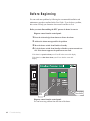
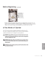
Before beginning. . . . . . . . . . . . . . . . . . . . . . . . . . . . . . . . . . . . . . . 6-2
A few words of caution . . . . . . . . . . . . . . . . . . . . . . . . . . . . . . . . . 6-3
i i l Ta b l e o f C o n t e n t s
DIAGNOSTICS
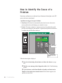
How to identify the cause of a problem . . . . . . . . . . . . . . . . . . . . . 6-4
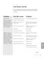
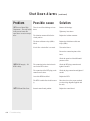
Shut down alarms . . . . . . . . . . . . . . . . . . . . . . . . . . . . . . . . . . . . . 6-5
Passive alarms . . . . . . . . . . . . . . . . . . . . . . . . . . . . . . . . . . . . . . . 6-8
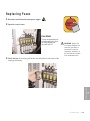
REPAIR
Replacing fuses. . . . . . . . . . . . . . . . . . . . . . . . . . . . . . . . . . . . . . . . 6-9
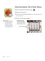
Checking heater solid state relays. . . . . . . . . . . . . . . . . . . . . . . . . 6-10
Checking or replacing temperature sensors . . . . . . . . . . . . . . . . . 6-11
Replacing the heating elements . . . . . . . . . . . . . . . . . . . . . . . . . . 6-12
Replacing the air flow differential pressure switch . . . . . . . . . . . . 6-14
A
Appendix
We’re here to help . . . . . . . . . . . . . . . . . . . . . . . . . . . . . . . . . . . . . A-1
How to contact customer service . . . . . . . . . . . . . . . . . . . . . . . . . . A-1
Before you call... . . . . . . . . . . . . . . . . . . . . . . . . . . . . . . . . . . . . . . A-1
Equipment guarantee . . . . . . . . . . . . . . . . . . . . . . . . . . . . . . . . . . A-2
Performance warranty . . . . . . . . . . . . . . . . . . . . . . . . . . . . . . . . . . A-2
Warranty limitations . . . . . . . . . . . . . . . . . . . . . . . . . . . . . . . . . . . . A-2
AD
Addendum
Blower installation and maintenance . . . . . . . . . . . . . . . . . . . . . . AD-1
✐
Note: This addendum applies only if you have purchased a Conair Hot
Air Dryer (HAD).
Ta b l e o f C o n t e n t s l i i i
i v l Ta b l e o f C o n t e n t s
SECTION
1
Purpose of the user guide . . . . . . . . . . . . . . 1-2
How the guide is organized . . . . . . . . . . . . . 1-2
Yo u r r e s p o n s i b i l i t i e s a s a u s e r . . . . . . . . . . . 1 - 3
AT T E N T I O N :
Read this so no one gets hurt . . . . . . . . 1-4
How to use the lockout device . . . . . . . . . . . 1-5
Introduction l 1-1
1
Introduction
Introduction
Purpose of the User Guide
This User Guide describes the Conair Hopper Temperature Controller
(HTC) process air heater and explains step-by-step how to install, operate, maintain and repair this equipment.
Before installing this product, please take a few moments to read the User
Guide and review the diagrams and safety information in the instruction
packet. You also should review manuals covering associated equipment in
your system. This review won’t take long, and it could save you valuable
installation and operating time later.
How the Guide is Organized
Symbols have been used to help organize the User Guide and call your
attention to important information regarding safe installation and operation.
Symbols within triangles warn of conditions that could be hazardous to users or
could damage equipment. Read and take precautions before proceeding.
1
Numbers indicate tasks or steps to be performed by the user.
◆
A diamond indicates the equipment’s response to an action performed by the user.
❒
An open box marks items in a checklist.
•
A circle marks items in a list.
✒
✐
Indicates a tip. A tip is used to provide you with a suggestion that will help you with
the maintenance and the operation of this equipment.
Indicates a note. A note is used to provide additional information about the steps
1-2 l Introduction
Yo u r R e s p o n s i b i l i t y a s a U s e r
• Thorough review of this User Guide, paying particular attention
•
•
•
to hazard warnings, appendices, and related diagrams.
Thorough review of the equipment itself, with careful attention
to voltage sources, intended use, and warning labels.
Thorough review of instruction manuals for associated equipment.
Step-by-step adherence to instructions outlined in this User Guide.
Introduction l 1-3
1
Introduction
You must be familiar with all safety procedures concerning installation, operation and maintenance of this equipment. Responsible safety procedures include:
AT T E N T I O N :
Read this so no one gets hurt
We design equipment with the user’s safety in mind. You can avoid the potential
hazards identified on this machine by following the procedures outlined below and
elsewhere in the User Guide.
WA R N I N G : I m p r o p e r i n s t a l l a t i o n , o p e r a t i o n , o r
servicing may result in equipment damage or
p e r s o n a l i n j u r y.
This equipment should be installed, adjusted, and serviced by qualified
technical personnel who are familiar with the construction, operation,
and potential hazards of this type of machine.
All wiring, disconnects, and fuses should be installed by qualified electrical technicians in accordance with electrical codes in your region.
Always maintain a safe ground. Do not operate the equipment at power
levels other than what is specified on the machine serial tag and data
plate.
WA R N I N G : Vo l t a g e h a z a r d
This equipment is powered by three-phase alternating current,
as specified on the machine serial tag and data plate.
A properly sized conductive ground wire from the incoming power
supply must be connected to the chassis ground terminal inside the
electrical enclosure (control center). Improper grounding can result in
severe personal injury and erratic machine operation.
Always disconnect and lock out the incoming main power source before
opening the control center or performing non-standard operating procedures, such as routine maintenance. Only qualified personnel should
perform troubleshooting procedures that require access to the control
center while power is on.
1-4 l Introduction
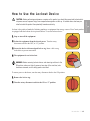
How to Use the Lockout Device
ON
2 Isolate the equipment from the electric power. Turn the rotary
O OFF
1 Stop or turn off the equipment.
disconnect switch to the OFF, or “O” position.
3 Secure the device with an assigned lock or tag. Insert a lock or tag
in the holes to prevent movement.
ON
O
OFF
4 The equipment is now locked out.
WARNING: Before removing lockout devices and returning switches to the
ON position, make sure that all personnel are clear of the machine, tools
have been removed, and all safety guards reinstalled.
To restore power to the heater, turn the rotary disconnect back to the ON position:
1 Remove the lock or tag.
OFF
O
2 Turn the rotary disconnect switch to the ON or “I ” position.
ON
Introduction l 1-5
1
Lockout is the preferred method of isolating machines or equipment from energy sources. Your Conair product
is equipped with the lockout device pictured below. To use the lockout device:
Introduction
CAUTION: Before performing maintenance or repairs on this product, you should disconnect and lockout electrical power sources to prevent injury from unexpected energization or start-up. A lockable device has been provided to isolate this product from potentially hazardous electricity.
1-6 l Introduction
SECTION
2
What is the HTC process air heater? . . . . . . . 2-2
Ty p i c a l a p p l i c a t i o n s . . . . . . . . . . . . . . . . . . 2 - 3
How it works . . . . . . . . . . . . . . . . . . . . . . 2-4
Specifications: HTC models 600 - 5000 . . . . . 2-6
Specifications: HTC for Hot Air Dryers (HAD) . 2-7
Description l 2-1
2
Description
Description
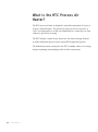
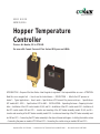
What is the HTC Process Air
Heater?
The HTC process air heater is designed to control the temperature of dry air as
it enters a material hopper. This process air heater can be set to increase, or
“raise”, the temperature of air that was dehumidified at a central dryer or from
a blower as part of hot air drying.
The HTC includes a control center, heater box with electric heating elements,
an airflow differential pressure switch, and an RTD temperature probe(s).
The differential pressure switch places the HTC in standby mode to save energy
and prevent heating element damage when air flow is not present.
2-2 l Description
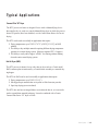
Ty p i c a l A p p l i c a t i o n s
Carousel Plus “W” Dryer
The HTC process air heater is designed for use with a dehumidifying device
that supplies dry air, such as a central dehumidifying dryer in which the process
heaters (if present) have been disabled, or with a stand alone blower for hot air
drying.
Hot Air Dryer (HAD)
The HTC process air heater, for use with a hot air dryer such as a Conair model
HAD, connects plant air motivated by a Conair blower assembly to a material drying hopper.
The HTC for HAD can be used successfully in applications that require:
• Drying temperatures up to 250°F (121.1°C).
• Non-hygroscopic materials that are in pellet or flake form (not powder).
• Open loop drying (not recirculated).
The HTC does not have an integral blower to circulate the hot air, so it can not be
used as a stand-alone material preheater. It must be combined with a Conair
Carousel Plus Series “W” dryer or HAD.
Description l 2-3
2
Description
The HTC can be used successfully in applications that require:
• Drying temperatures up to 350°F (176.7°C) (250°F [121.1°C] on HAD
models).
• The ability to dry multiple materials requiring different drying temperature
setpoints in a central drying system. (Requires separate HTCs / hoppers.)
• The ability to easily take a hopper “off-line” for cleaning without shutting
down the entire central drying system.
H o w i t Wo r k s
The HTC process air heater works a lot like the thermostat and heater in your
house. The RTD probe measures the temperature of the air entering the hopper.
If this air is not warm enough to properly dry the material in the hopper, the
RTD sends a message to the temperature controller which tells the heater to
begin heating. The heating elements inside the heater enclosure heat until the
RTD probe senses that the air entering the hopper is at the setpoint entered by
the user.
The HTC has a process protection RTD (over-temperature safety). The temperature controller shuts off power to the heating elements if they get too hot and
an alarm is generated.
An air flow differential pressure switch detects air flow by sensing the natural
drop of pressure due to flow through the heater. This prevents damage to the
heater elements or material in the hopper on loss of air flow.
The temperature controller alarms if the heating elements are heating too hot. It
also alarms if the heating elements are not heating enough.
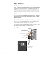
How the HTC Works
Hopper Inlet
Process Temperature RTD
Process Protection RTD
Heater Box
Heating Element
Startup /
Shutdown
Drying Hopper Temperature Control
Heaters
Enable
Standby
For Startup:
1. With heaters in
Standby, turn on
blower or dryer.
2. Enable heaters.
For Shutdown:
1. Switch heaters to
Standby.
2. Wait 60 seconds
before turning off
blower or dryer.
Temperature Controller
Control Center
2-4 l Description
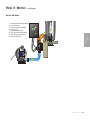
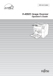
H o w i t Wo r k s
(continued)
How the HAD Works
Centrifugal Blower Assembly
Control Center
Electric Heater Assembly
Hose (15 ft)
Insulated Hose (3 ft)
RTD Process Temperature
RTD Process Protection
Outlet Filter Sock
Drying Hopper Temperature Control
8
6
2
5
7
3
1
4
Description l 2-5
2
Description
1
2
3
4
5
6
7
8
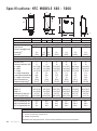
Specifications: HTC MODELS 600 - 5000
C
B
D
A
F
E
I
G
MODEL HTC
Carousel Plus dryer model
Performance characteristics
Temperature range
Flow rate cfm
Pressure drop@flow rate
inches WC†
{mm} WC†
HTC-30H*
HTC-60H*
HTC-90H*
HTC-120H*
HTC-180H*
HTC-270H*
W600
W800 W1000
W1600
W2400
W3200
W5000
1600
2500
300
3.0
{76.2}
400
500
150° - 375° F {66° - 191° C}
800
1200
1.8
2.3
{45.7} {58.4}
4.0
{101.6}
3.8
{96.5}
5.9
{149.9}
6.4
{162.6}
8
8
31.4 {79.8}
10.1 {25.7}
10.7 {27.2}
1.75
{4.4}
10.6
{26.9}
38 {17}
8
8
27.5 {69.9}
13.6 {34.5}
10.9 {27.7}
1.5
{3.8}
7.1
{18.0}
37 {17}
12
12
27.0 {68.6}
16.0 {40.6}
10.9 {27.7}
2.0
{5.1}
8
{20.3}
78 {35}
12
12
31.0 {78.7}
16.0 {40.6}
16.0 {40.6}
1.0
{2.5}
10
{25.4}
93 {43}
12
12
34.0 {86.4}
18.0 {45.7}
17.0 {43.2}
2.0
{5.1}
13
{33.0}
102 {46}
12
12
36.4 {92.5}
24.2 {61.5}
17 {43.2}
1.0
{2.5}
15.4
{39.1}
131 {59}
24.0 {61.0}
24.0 {61.0}
10.0 {25.4}
3.0 {7.6}
150.0 {68.0}
24.0 {61.0}
24.0 {61.0}
10.0 {25.4}
3.0 {7.6}
150.0 {68.0}
36.0 {91.4}
48.0 {122.0} 60.0 {152.4}
30.0 {76.2}
36.0 {91.4} 42.0 {106.7}
10.0 {25.4}
10.0 {25.4} 12.0 {30.5}
3.0 {7.6}
3.0 {7.6}
3.0 {7.6}
180.0 {81.6} 250.0 {113.0} consult Conair
60.0 {152.4}
42.0 {106.7}
12.0 {30.5}
3.0 {7.6}
43.3
37.7
30.1
86.6
75.4
60.2
Dimensions inches {cm} and weight lb {kg}
Heater box dimensions
Inlet size (OD)
Outlet size selection (OD)
A - Height
B - Width
C - Depth
D - Height of discharge
nozzle above the heater box
E - Height of inlet nozzle
below the heater box
Installed weight lb {kg}‡
Control center dimensions
Height - F
Width - G
Depth - H
Clearance for heat sink - I
Installed weight lb {kg}
Voltage Full Load Amps
400 V/3 phase/50-60 Hz
480 V/3 phase/50-60 Hz
575 V/3 phase/50-60 Hz
TPDS022-0106
129.9
113.1
90.3
173.2
150.8
120.4
259.8
226.2
180.6
SPECIFICATION NOTES:
*
†
The HTC model number reflects the kilowatts of each unit. For example, HTC-60 has a 60 kilowatt heater.
The unit of measure WC is water column.
‡ Weights are approximate.
Specifications may change without notice. Consult a Conair representative for the most current information.
2-6 l Description
consult Conair
389.7
339.3
270.0
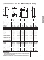
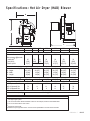
Specifications: HTC for Hot Air Dryers (HAD)
C
B
D
F
A
E
I
Hot air dryer model
Performance characteristics
Temperature range
Flow rate cfm
Pressure drop@flow rate
inches WC†
{mm} WC†
HTC-30B*
HTC-30A*
HTC-60A*
HTC-90A*
HTC-120A*
HTC-180A*
800
1000
1600
2400
3200
5000
300 400
500
1600
2500
3.0 5.0
{76.2} {127}
3.2
{81.2}
5.4
{137.2}
6.1
{155.0}
6.4
{163.0}
8.0
{203.2}
5
5
31.4 {79.8}
10.1 {25.7}
10.7 {27.2}
0 {0}
5
5
27.5 {69.9}
13.6 {34.5}
10.7 {27.2}
5.9 {15.0}
8
8
27.5 {69.9}
13.6 {34.5}
10.9 {28.0}
2.0 {5.1}
8
8
32.0 {81.3}
15.9 {40.4}
16.0 {40.6}
1.0 {2.5}
8
8
31.0 {79.0}
16.0 {40.6}
17.0 {43.2}
2.0 {5.1}
12
12
34.0 {86.3}
18.0 {45.7}
20.0 {50.8}
1.0 {2.5}
8.0 {20.3}
37 {17}
11.4 {30.0}
58 {26}
8.0 {20.3}
78 {35}
11.0 {27.9}
93 {42}
13.0 {33.0}
102 {46}
13.0 {33.0}
131 {59}
24.0 {61.0}
24.0 {61.0}
10.0 {25.4}
3.0 {7.6}
150.0 {68.0}
24.0 {61.0}
24.0 {61.0}
10.0 {25.4}
3.0 {7.6}
150.0 {68.0}
24.0 {61.0}
24.0 {61.0}
10.0 {25.4}
3.0 {7.6}
150.0 {68.0}
36.0 {91.4}
30.0 {76.2}
10.0 {25.4}
3.0 {7.6}
180.0 {81.6}
48.0 {122.0}
36.0 {91.4}
10.0 {25.4}
3.0 {7.6}
250.0 {113.0}
60.0 {152.4}
42.0 {106.7}
12.0 {30.5}
3.0 {7.6}
43.3
37.7
30.1
43.3
37.7
30.1
86.6
75.4
60.2
129.9
113.1
90.3
173.2
150.8
120.4
259.8
226.2
180.6
600
120° - 250° F {49° - 121° C}
800
1200
Dimensions inches {cm} and weight lb {kg}
Heater box dimensions
Inlet size (OD)
Outlet size selection (OD)
A - Height
B - Width
C - Depth
D - Height of discharge
nozzle above heater box
E - Height of inlet nozzle
below the heater box
Installed weight lb {kg}
Control center dimensions
F - Height
G - Width
H - Depth
I - Clearance for heat sink
Installed weight lb {kg}
Voltage Current Amps
400V/3 phase/50-60 Hz
460 V/3 phase/50-60 Hz
575 V/3 phase/50-60 Hz
SPECIFICATION NOTES:
*
The HTC model number reflects the kilowatts of each unit. For example, HTC-60 has a 60 kilowatt heater.
†
The unit of measure WC is water column.
Specifications may change without notice. Consult a Conair representative for the most current information.
consult Conair
TPDS024-0106
Description l 2-7
2
MODEL HTC
H
Description
G
2-8 l Description
SECTION
3
Installation
Unpacking the boxes . . . . . . . . . . . . . . . . . 3-2
Preparing for installation . . . . . . . . . . . . . . 3-3
Installation of the HTC control models
HTC 30, 60 and 90 . . . . . . . . . . . . . . . . 3-3
Installation of the HTC control model
Installation of the HTC control models
HTC 180 and 270 . . . . . . . . . . . . . . . . . 3-4
Location and mounting of the HTC heater
assembly models 30, 60, and 90 . . . . . . 3-5
Location and mounting of the HTC heater
assembly model HTC 120 . . . . . . . . . . . 3-5
Location and mounting of the HTC heater
assembly models 180 and 270 . . . . . . . . 3-5
Connecting the HTC heater assembly
to the dryer or blower and hopper . . . . . 3-6
Installing the isolation valves . . . . . . . . . . . 3-7
Connecting the power on models
HTC 180 and 270 . . . . . . . . . . . . . . . . . 3-8
Connecting the control wires on
models HTC 180 and 270. . . . . . . . . . . 3-10
C o n n e c t i n g t h e RT D s e n s o r s . . . . . . . . . . . 3 - 1 1
Te s t i n g t h e i n s t a l l a t i o n . . . . . . . . . . . . . . . 3 - 1 5
Installation l 3-1
3
Installation
HTC 120 . . . . . . . . . . . . . . . . . . . . . . . 3-4
Unpacking the Boxes
The HTC process air heater comes in two boxes. Depending on the model and
options ordered, the boxes could include:
Standard Equipment
•
•
•
•
•
•
•
Heater assembly;
Control center;
1 insulated hose;
1 non-insulated hose;
4 hose clamps;
2 RTD probes (1 process and 1 process protection);
Blower (HAD models only).
Optional Equipment
• 1 RTD probe (1 setback).
1 Carefully remove all components from their shipping containers.
2 Remove all packing material, protective paper, tape, and plastic.
3 Carefully inspect all components to make sure no damage occurred during
shipping, and that you have all the necessary hardware.
4 Take a moment to record serial numbers and electrical power specifications
in the blanks provided on the back of the the User Guide’s title page. The information will be helpful if you ever need service or parts.
5 You are now ready to begin installation. Follow the preparation steps on the
next page.
3-2 l Installation
Preparing for Installation
The HTC process air heater is easy to install, if you prepare the mounting area
properly.
1 Make sure the mounting area provides:
❒ A grounded power source supplying the correct current for your
HTC model. All models require three-phase power. Check the HTC’s
serial tag for the correct amps, voltage, and cycles. Field wiring
should be completed by qualified personnel to the planned location for
the HTC. All electrical wiring should comply with your region’s electrical codes.
❒ Process air lines installed from the dryer to the HTC location. For
easy maintenance, we recommend using flexible hose to make the final
connection between the process outlet of the dryer or blower and the
HTC.
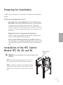
Installation of the HTC Control
Models HTC 30, 60, and 90
✐
HTC Control
Center
CAUTION: You are responsible for the structural integrity of this
installation.
NOTE: The HTC control is shipped mounted on the left side of the
floor stand on models 30, 60, and 90 (see figure to the right).
✐
NOTE: If, by using your own provisions, you change the mounting
arrangement of the control center to a wall mount unit, it must be
mounted 6 inches off of the wall to provide clearance for the heat
sink.
Installation
l 3-3
3
Description
❒ Minimum clearance for safe operation and maintenance.
The HTC control center should be mounted so that its display panel
can be seen and touched easily by an operator.
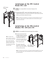
Installation of the HTC Control
Model HTC 120
HTC Control
Center
CAUTION: You are responsible for the structural integrity of this
installation.
1 Securely bolt the HTC control to the left side of the floor stand. Use the
supplied locking fasteners to securely mount the HTC control center to the floor
stand to prevent vibration-induced loosening.
✐
NOTE: If, by using your own provisions, you change the mounting arrangement of the control center to a wall mount unit, it must be mounted 6 inches off of the wall to provide
clearance for the heat sink.
Installation of the HTC Control
Models HTC 180 and 270
CAUTION: You are responsible for the structural integrity of this installation.
1 Move the control center into
✐
Note: If the length of the
process and process protection
RTD is too short for your installation, contact Conair Parts
Department (800.458.1960) to
its final location for operation
(see figure to the right). The
control center must be positioned close enough to the hopper to allow connection of the
RTD temperature probe.
purchase an extension cable.
From outside the United States,
call 814.437.6861.
✐
The control center can be
HTC Control Center
mounted to a wall, the hopper
frame, or a floor stand with cus- (Free-Standing)
tomer provided provisions.
Note: If, by using your own provisions, you change the mounting arrangement of the control
center to a wall mount unit, it must be mounted 6 inches off of the wall to provide clearance for the heat sink.
3-4 l Installation
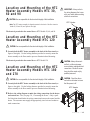
Location and Mounting of the HTC
Heater Assembly Models HTC 30,
60 and 90
✐
IMPORTANT: Always refer to
the wiring diagrams that came
with your heater before making
electrical connections.
CAUTION: You are responsible for the structural integrity of this installation.
HTC Heater
Note: The HTC heater assembly is shipped mounted to the back of the floor stand on
Models 30, 60 and 90 (see Figure to the right).
The heater is prewired to the control box on HTC Models 30, 60, and 90.
Location and Mounting of the HTC
Heater Assembly Model HTC 120
CAUTION: You are responsible for the structural integrity of this installation.
figure to the right). Use the locking fasteners provided to securely mount the
heater assembly to the floor stand to prevent vibration induced loosening.
The heater is prewired to the control box on HTC Model 120.
Location and Mounting of the HTC
Heater Assembly Models HTC 180
and 270
CAUTION: You are responsible for the structural integrity of this installation.
1 Securely bolt the HTC heater assembly to the back of the floor stand (see
figure to the right). Use the locking fasteners provided to securely mount the
heater assembly to the floor stand to prevent vibration induced loosening.
CAUTION: Always disconnect
and lock out the main power
sources before making electrical
connections. Electrical connections should be made only by
qualified personnel.
CAUTION: Check the disconnect with a volt meter to insure
that the power is off.
HTC Heater
2 Refer to the wiring diagram to make the wiring connections for the heater
and control box. Also, see page 3-8, “Connecting the Power.” Only a qualified electrician should make the wiring connections between the control and the
heater. The customer must supply the appropriately sized wire and conduit to
make connections.
Installation l 3-5
3
Description
1 Securely bolt the HTC heater assembly to the back of the floor stand (see
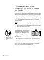
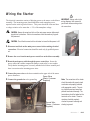
Connecting the HTC Heater
Assembly to the Dryer or Blower
and Hopper
The inlet of the HTC heater assembly should be plumbed to the air source (usually
a blower or central dehumidification dryer). This inlet hose should be at least the
size of the heater inlet (lower) connection size (hoses provided). Also, the hose
should be as short and straight as possible to prevent unnecessary frictional losses.
This hose is the un-insulated and will normally be at ambient temperature plus 50
to 90°F. This hose should be properly supported so no weight will be on the
heater inlet connection.
The connection between the heater assembly outlet and the hopper should
be made with the supplied insulated hose. The insulation is important from
an energy standpoint and for personnel protection. Be careful not to block
off any heater sensor mounting locations.
Make sure all hoses are securely clamped to
prevent wasteful leaking. The hoses should be
routed neatly and supported where possible to
prevent undue stress on the heater and hopper
assemblies. Also, the bends should be made
with gradual radiuses. Sharp turns will cause
undue pressure drop.
✐
NOTE: Do not allow the
flexible hoses to kink or
crimp.
✒
TIP: Units with elliptical or oval shaped inlets or outlets require forming the hose to fit
this shape. When tightening the hose clamp, position the screw head on the long radius
portion of the duct.
Connect the filter sock or optional dust collector or cyclone to the hopper discharge. Verify the connections are secure and do not leak.
3-6 l Installation
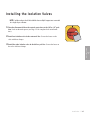
I n s t a l l i n g t h e I s o l a t i o n Va l v e s
✐
NOTE: Isolation valves should be installed when multiple hoppers are connected
to a single dryer or blower.
ON
O
tion. Lock out the main power (see Page 1-5 for complete lock out information).
OFF
1 Turn the disconnect dial on the control center door to the Off or “O” posi-
2 Install one isolation valve in the return air line. Secure the hoses on the
valve with hose clamps.
3 Install the other isolation valve in the delivery air line. Secure the hoses on
the valve with hose clamps.
3
Description
Installation l 3-7
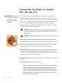
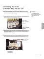
C o n n e c t i n g t h e Po w e r o n m o d e l s
HTC 180 and 270
IMPORTANT: Always refer
to the wiring diagrams that
came with your heater
before making electrical
connections.
The electrical connection consists of bringing power into the control center and
wiring the heater power from the control center to the heater assembly. The incoming power should match the rated nameplate power required on the serial tag on the
control center. This power should be clean and have a voltage variation of no more
than +/- 5% of the nameplate voltage. Unless the actual voltage is equal to the
nameplate voltage, the actual kW output of the HTC will vary slightly. The output
varies with the square of the voltage difference.
CAUTION: Always disconnect and lock out the main power sources before making electrical connections. Electrical connections should be made only by qualified personnel.
O
OFF
ON
CAUTION: Check the disconnect with a volt meter to insure that the power is off.
1 Disconnect and lock out the main power sources before making electrical
connections. Electrical connections should be made only by qualified personnel.
2 Turn the disconnect dial on the control center door to the Off or “O” position. Turn the captive screw, and swing the control center door open.
3 Insert the main power cable through a knockout in the side of the control center.
Secure the power cable with a rubber compression fitting or strain relief or use
conduit. Verify that the incoming power is securely attached to the control center
and there is no strain on the incoming power.
4 Connect the power wires to the three terminals at the top of the power disconnect
holder.
5 Connect the ground wire to the ground lug.
✐
Note: The connection between the heater and control center should be made with
properly sized conductors and properly protected with appropriate conduit (customer supplied). The routing should be neat and away from potential mechanical
damage. The terminations should be landed on the terminals in the control center
and heater junction area. These terminations should be regularly checked to prevent loosening and shorting to ground.
3-8 l Installation
C o n n e c t i n g t h e Po w e r ( c o n t i n u e d )
on models HTC 180 and 270
6 Insert the supplied heater power wire through a knockout in the side or
bottom of the control center. Secure the wire with a rubber compression fitting or strain relief if conduit is not used.
7 Connect the heater power wires to the control center’s terminal block and
IMPORTANT: Always refer to
the wiring diagrams that
came with your heater before
making electrical connections.
heater ground wire to the ground lug as shown.
Power Wires
(Gray - Customer
Supplied)
8 Insert the other end of heater power wire through the knockout in the side
of the heater assembly. Secure the wire with a rubber compression fitting or
strain relief if conduit is not used.
9 Connect the heater power wires to the top terminals of the heater assembly’s terminal block and heater ground wires to the ground lug as shown.
Insert the Power
Wires Here
Ground Wires
(Green/Yellow)
Installation l 3-9
3
Description
Ground Wires
(Green - Customer
Supplied)
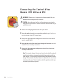
Connecting the Control Wires
Models HTC 180 and 270
ON
OFF
IMPORTANT: Always refer to the proper wiring diagram supplied with your
equipment before making electrical connections.
O
CAUTION: Always disconnect and lock out the main power sources before
making electrical connections. Electrical connections should be made only by
qualified personnel.
1 Refer to the wiring diagram that came with your control.
2 Insert the supplied control wires encased in conduit through a knockout in
the side or bottom of the HTC control center.
3 Connect the high temperature and pressure switch wires to the control
center's terminal block.
4 Insert the other end of the control wires through the knockout in one side
of the HTC heater assembly terminal box.
5 Connect the high temperature and pressure switch wires to the heater
assembly terminal block.
✐
Note: The connection between the heater and control center should be made with
properly sized conductors and properly protected with appropriate conduit (customer supplied). The routing should be neat and away from potential mechanical
damage. The terminations should be landed on the terminals in the control center
and heater junction area. These terminations should be regularly checked to prevent loosening and shorting to ground.
3-10 l Installation
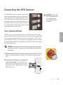
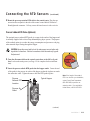
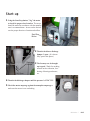
C o n n e c t i n g t h e RT D S e n s o r s
The lower RTD could be the return air sensor for the
setback option if installed or the process protection
sensor depending on the configuration of the system.
The routing of the sensor cables should be neat and
not parallel with the power connections. When a sensor cable must cross over power wiring, the intersection should be made at right angles to reduce the RFI
noise transmitted to the sensor cable.
IMPORTANT: Always refer
to the wiring diagrams that
came with your heater
before making electrical
connections.
Process Temperature RTD Probe
CAUTION: Always disconnect and lock out the main power sources before making electrical connections. Electrical connections should be made only by qualified personnel.
1 Turn the disconnect dial on the control center door to the Off or “O” posi-
OFF
tion. Lock out the main power (see Page 1-5 for complete lock out information).
O
ON
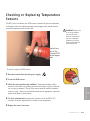
2 Insert the process RTD probe into the delivery
air inlet on the hopper. Center the end of the
probe in the inlet so that the tip does not touch
the inlet tube walls. Tighten the nuts to lock the
RTD probe in place.
(continued)
Installation l 3-11
3
Description
The RTD sensor connections should be made to the control center via the upper
female connections in the side of the control center. The process temperature RTD
is to be located in the hopper delivery air inlet. The connection is 1/8 NPT. The
sensor should be located ¼ to ¾ of the way in to the diameter of the inlet to obtain
the best temperature reading. The controller uses this RTD to monitor and control
the setpoint temperature.
C o n n e c t i n g t h e RT D S e n s o r s
(continued)
3 Route the process temperature RTD cable to the control center. Plug the connector into receptacle in the side of the control center labeled “Process”. Hand
tighten the connector. Coil any excess cable and secure it with a wire tie.
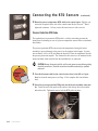
Process Protection RTD Probe
The optional process protection RTD probe is a safety sensor that prevents the
heater from overheating in case of a process temperature sensor failure or insulated
hose failure.
The process protection RTD sensor senses the temperature leaving the heater
assembly to prevent damage to the process or the product in the hopper. It generates an alarm (A-49 or A-50) and shuts the heater off if the air temperature exceeds
the process protection setpoint. The element for this sensor is to be mounted in the
heater assembly outlet nozzle before the insulated hose is connected.
O
OFF
ON
CAUTION: Always disconnect and lock out the main power sources before making
electrical connections. Electrical connections should be made only by qualified
personnel.
1 Turn the disconnect dial on the control center door to the Off or O position. Lock out the main power (see Page 1-5 for complete lock out information).
2 Insert the process protection RTD probe into the heater assembly outlet nozzle. Center the end of the probe in the outlet so that the tip does not touch the
inlet tube walls. Tighten the nuts to lock the RTD probe in place.
Process
Protection
RTD
Probe
3-12 l Installation
C o n n e c t i n g t h e RT D S e n s o r s
(continued)
3 Route the process protection RTD cable to the control center. Plug the connector into the receptacle in the side of the control center labeled “Protection”.
Hand tighten the connector. Coil any excess cable and secure it with a wire tie.
Process Setback RTD Probe (Optional)
The optional process setback RTD probe is a sensor in the outlet of the hopper and
is normally supplied with a closed loop dehumidifying dryer system. The purpose
of the setback option is to reduce the energy consumption and prevent over drying
when material stops flowing through the hopper.
ON
OFF
1 Turn the disconnect dial on the control center door to the Off or O posi-
O
tion. Lock out the main power (see Page 1-5 for complete lock out information).
2 Insert the process setback RTD probe into the hopper outlet. Center the end
of the probe in the process air outlet of the hopper so that the tip does not touch
the outlet tube walls. Tighten the nuts to lock the RTD probe in place.
✐
Note: If the length of the setback
Process
Setback RTD
Location
RTD is too short for your installation,
Typical Hopper
contact Conair Parts Department
(800.458.1960) to purchase an
extension cable. From outside the
United States, call 814.437.6861.
Process Air
Outlet
(continued)
Installation l 3-13
3
Description
CAUTION: Always disconnect and lock out the main power sources before making electrical connections. Electrical connections should be made only by qualified personnel.
C o n n e c t i n g t h e RT D S e n s o r s
(continued)
3 Route the process setback RTD cable to the control center. Plug the connector
into the lower receptacle in the side of the control center. Hand tighten the connector. Coil any excess cable and secure it with a wire tie.
3-14 l Installation
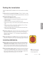
Te s t i n g t h e I n s t a l l a t i o n
You have completed the HTC installation. Now it’s time to make sure everything
works.
1 Make sure there is no material in the hopper. If there is a loader or vacuum
receiver mounted on the hopper, disconnect the material inlet hose at the source.
2 Perform the following safety checks:
•
•
•
•
3 Perform a resistance test. Check the resistance leg to leg and leg to ground to
make sure that each heater and blower are wired correctly. The three legs
should have equal resistance +/- 5%. The resistance to ground should be 20
megohms or higher.
ON
O
ON position. This powers up the control and the display lights will illuminate.
OFF
4 Turn on the main power to the HTC. Make sure the disconnect dial is in the
For Hot Air Dryer (HAD) Models Only
5 Bump (rapidly start and stop) the blower motor and verify the motor is
turning in the correct rotation according to the labels on the motor. If the
rotation is incorrect, shut off and lock out power and switch any two of the
three power legs on the line side of the disconnect provided with the blower.
6 Check the discharge damper setting. The handle on the outlet of the blower
is connected to the discharge damper. This is required to be set to the proper
position to determine the proper airflow for the heater/hopper. Adjust the discharge damper until the blower pressure is 20 to 30 in. W.C.
(continued)
✐
NOTE: See the blower specifications sheet in the appendix
for design supply pressure.
Installation l 3-15
3
•
Description
•
Make sure all components are securely mounted;
Make sure all hoses are connected to the proper locations and secured
with hose clamps;
Make sure all sensors are properly installed and secured:
Make sure all wiring is secure and away from potential mechanical damage;
Make sure the air filter is clean and has a minimum of 6 in. (15.2 cm)
clearance without any flow obstructions; and
Make sure the hopper outlet is free from obstructions that would cause
back pressure in the drying hopper.
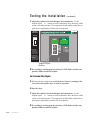
Te s t i n g t h e I n s t a l l a t i o n
(continued)
7 Adjust the setpoint to the desired hopper inlet temperature. Use the
Setpoint Adjust ▲ or ▼ buttons to set the temperature. Move the heater enable
switch to the enable position. The temperature should stabilize around the setpoint and not significantly overshoot the set temperature.
Startup /
Shutdown
Heaters
Enable
Standby
For Startup:
1. With heaters in
Standby, turn on
blower or dryer.
2. Enable heaters.
For Shutdown:
1. Switch heaters to
Standby.
2. Wait 60 seconds
before turning off
blower or dryer.
Setpoint Adjust
Buttons
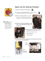
8 If everything is working properly, the heater’s LED flashes and the temperature climbs towards the setpoint.
For Carousel Plus Dryers
5 Reference the dryer manual and verify the dryer’s blower is running in the
correct direction and the dryer is ready for operation.
6 Start the dryer.
7 Adjust the setpoint to the desired hopper inlet temperature. Use the
Setpoint Adjust ▲ or ▼ buttons to set the temperature. Move the heater enable
switch to the enable position. The temperature should stabilize around the setpoint and not significantly overshoot the set temperature.
8 If everything is working properly, the heater’s LED flashes and the temperature climbs towards the setpoint.
3-16 l Installation
SECTION
4
Operation
The HTC process air heater: control
panel DC . . . . . . . . . . . . . . . . . . . . . . 4-2
Control function flow charts . . . . . . . . . . . . 4-3
Control function descriptions . . . . . . . . . . . 4-6
HTC DC control alarms . . . . . . . . . . . . . . . 4-19
Initial operation (for HAD only) . . . . . . . . . 4-20
Initial operation (for Carousel Plus
dryer HTC) . . . . . . . . . . . . . . . . . . . . 4-21
Autotuning . . . . . . . . . . . . . . . . . . . . . . . 4-22
Normal operation to start heating . . . . . . . . 4-24
Normal operation to stop heating . . . . . . . . 4-25
Operation l 4-1
4
Operation
HTC DC control functions . . . . . . . . . . . . . . 4-3
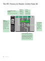
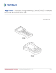
T h e H T C P r o c e s s A i r H e a t e r : C o n t r o l Pa n e l D C
Increment/Decrement
Buttons
Used to increase or decrease values.
Setpoint
Display
Actual
Display
Shows the setpoint value.
Shows the actual
temperature value.
Startup /
Shutdown
Heaters
Enable
Heater
Enable/Standby
Also is used to reset
shut down alarms (see
“Troubleshooting”
Section 6) and to
“Autotune” the controller (see
“Autotuning” Section
4).
Scroll Button
Standby
Press to scroll
through the
closed loop menu
list. Pressing the
Scroll button
moves you down
the list.
For Startup:
1. With heaters in
Standby, turn on
blower or dryer.
2. Enable heaters.
For Shutdown:
1. Switch heaters to
Standby.
2. Wait 60 seconds
before turning off
blower or dryer.
Acknowledge Alarm Button
Under an alarm condition, pushing the
Acknowledge button once turns off the
horn and displays the alarm message.
Pushing the Acknowledge button a second time turns off the alarm LED.
4-2
l Operation
HTC DC Control Functions
HTC functions are values that you can set or monitor. Press the Scroll button until
the function you want to set or monitor appears in the LED display.
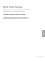
Control Function Flow Charts
The following flow charts provide a quick summary of the control functions. For
an explanation of each control function, see Control Function Descriptions.
4
Operation
Operation l 4-3
POWER ON
(Default Screen)
1
888
888
2 sec All LEDs On
2
dC
004
2 sec Software Version
3
res
in
4
250
250
Process Setpoint and Actual Temp (Default Screen)
Press + or - to change setpoint.
Press Scroll Button for Process Deviation Alarm Setpoint (Dev)
5
5
dEv
+ or - Deviation Band
Press + or - to change setpoint.
Press Scroll to enter the value
Press Scroll Button again for Setback
Return Temperature Setpoint
5A
180
Srt
(Optional)
Press + or - to change setpoint.
Press Scroll to enter the value
Press Scroll Button again for Process
Setback Temperature Setpoint
5B
140
PSt
Press + or - to change setpoint.
Press Scroll to enter the value
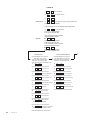
Process Screens
Press Scroll Button and + key at the
same time again for 2 sec to get in.
To get out at any time Press Scroll
button and - key at the same time
Press Scroll again to view next screen
Press Scroll again to view next screen
7
375
Hi.L Process High Limit
Press Scroll again to view next screen
8
3
Lbb Process Loop Break Band
Press Scroll again to view next screen
9
10
Lbt
Process Loop Break Time
Press Scroll again to view next screen
10
385
H.AL Process High Alarm Setpoint
17
Pro
Act
tEc
250
Protect Temperature
Press Scroll again to view next screen
18
625
H.Al
Protect Hi Alarm SP
Press Scroll again to view next screen
19
10
H.dL
Protect Hi Alarm Delay
Press Scroll again to view next screen
20
300
d.AL Differential Alarm SP
Press Scroll again to view next screen
11
21
50
12
16
Pb
Process Prop
int
Process Integral
Press Scroll again to view next screen
13
2
dEr
Process Derivative
Press Scroll again to view next screen
14
tun
OFF Process Autotune
Press + Key to Start Autotune
Press Scroll again to view next screen
15
F
unt
Units degrees F or degrees C
Press + Key to toggle between F and C
Press Scroll again to view the first screen
l Operation
16
Press Scroll again to view next screen
Press Scroll again to view next screen
4-4
Process Protection Screens
Press Scroll Button and + key at the
same time for 2 sec to get in.
To get out at any time Press Scroll
button and - key at the same time
2 Min timer then return to the default screen
6
Pro
cES
80
d.dL
Differential Alarm Delay
Press Scroll again to view the first screen
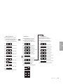
Setback Setup Screens
Press Scroll Button and + key at the
same time again for 2 sec to get in.
To get out at any time Press Scroll
button and - key at the same time
Set
bAc
31
ret
250
Press Scroll again to view next screen
32
20
ban
Press Scroll again to view next screen
33
10
sls
Press Scroll again to view next screen
34
Ldr
0
Press Scroll again to view next screen
34A Sbt
OFF
SEt
uP
43
Press Scroll again to view next screen
37
tyP
Res
Controller Type
Press Scroll again to view next screen
38
Prt
ON Process Protection Install
Press Scroll again to view next screen
39
Stb
OFF Setback Install
Press Scroll again to view next screen
40
Id
1
Not applicable to the HTC
Press Scroll again to view next screen
41
tSt
OFF Goto Test Mode
Press Scroll again to view next screen
34B SbL
35
2
P.dL
Press Scroll again to view next screen
35A
10
tE
St
Press Scroll again to view next screen
44
in.1
OFF Digital Input 1 status
Press Scroll again to view next screen
45
in.2
OFF Digital Input 1 status
Press Scroll again to view next screen
47
in.4
ON
Digital Input 4 status
Press Scroll again to view next screen
50
ou.3
OFF Press + key to jog output 3
Press Scroll again to view next screen
52
ou.5
OFF Press + key to jog output 5
Press Scroll again to view next screen
Press Scroll again to view next screen
53
42
Press Scroll again to view the first screen
OFF
Press Scroll again to view next screen
To get out at any time Press Scroll
button and - key at the same time
Ld.d
OFF Load Default
ou.6
OFF Press + key to jog output 6
Press + Key to Load Default
Press Scroll again to view the first screen
Add
res
A.dL
Press Scroll again to view next screen
0
500
24
501
2
502
23
503
4
504
Operation l 4-5
4
Press Scroll again to view next screen
36
Test Mode Screens
* The test mode screens become
visable if tSt (screen 41) is turned on.
Operation
30
Setup Screens
Press Scroll Button and + key at the
same time for 10 sec to get in.
To get out at any time Press Scroll
button and - key at the same time
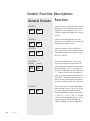
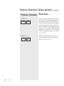
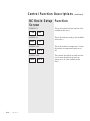
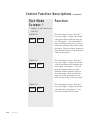
Control Function Descriptions
General Screens
Function
SCREEN 1
Once the power is turned on, this screen is
displayed for 2 seconds while the control
performs its self-checking process. All
LEDs are illuminated during this 2-second
interval.
888
888
SCREEN 2
dC
004
SCREEN 3
res
in
SCREEN 4
Setpoint
Actual
250
250
SCREEN 5
20
4-6
l Operation
dEv
After the self-checking process is complete, this screen flashes for 2 seconds and
displays the software version.
After the software version is displayed,
this screen appears for 2 seconds and identifies that the control is setup for a wheel
dryer (2) or HAD.
This is the default screen. It shows the
process air temperature setpoint and the
actual temperature measured at the inlet to
the drying hopper. The “+/-” buttons can
be used to change the setpoint. Holding the
“+/-” buttons in will cause the number to
ramp up or down faster the longer the button is held. The display will return to the
default screen from anyplace in the menu
structure if nothing is done for 10 minutes.
This is the process deviation temperature
alarm setpoint screen. It is used to set the
deviation temperature band around the
process temperature setpoint. The range is
5 - 20°F (2.8 - 11.1°C). The “+/-” buttons
can be used to change the setpoint. If the
temperature goes outside the band, the
control will display a passive alarm (P1).
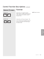
Control Function Descriptions
(continued)
General Screens
Function
SCREEN 5A
Srt
Setback Screen 1 (Setback Setpoint).
When setback is enabled, this is the hopper
outlet temperature at which the setback
becomes active.
PSt
Setback Screen 2 (Process Setpoint). The
process setpoint is the temperature the control tries to maintain when functioning in
the setback mode.
180
SCREEN 5B
140
✐
NOTE: Setback is optional.
4
Operation
Operation l 4-7
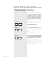
Control Function Descriptions
Process Screens
(continued)
Function
To access the process screens, press the
“Scroll” and “+” buttons at the same time
and hold for two seconds . To get out of
the Process screens at any time, press the
Scroll and “-” buttons at the same time.
After two minutes, you will be returned to
the Default screen.
SCREEN 6
Pro
cES
SCREEN 7
250
Hi.L
SCREEN 8
3
4-8 l Operation
Lbb
This is the process header screen. It indicates that all items below it pertain to the
process temperature control.
This is the process high limit screen. It is
used to set the high limit for the process
temperature setpoint. The “+/-” buttons
can be used to change this value. If set at
250°F, the operator cannot set the process
setpoint above 250°F.
This is the process loop break band screen.
It is used to set the temperature band for
the loop break alarm. The “+/-” buttons
can be used to change the setpoint. If outside the deviation band, if the actual temperature does not move toward the setpoint
by this value in the time value in screen 9,
a loop break alarm will occur.
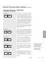
Control Function Descriptions
(continued)
Process Screens
Function
SCREEN 9
This is the process loop break time screen.
It is used to set the temperature band time
for the loop break alarm. The “+/-” buttons can be used to change the temperature
band time. When the actual temperature is
outside the deviation band, if the temperature is not moving toward the setpoint at a
rate greater than or equal to the value in
screen 8, page 4-8, for the time value in
this screen (sec.), then the heater will
alarm on loop break. Once the actual temperature is within the deviation band, the
loop break is ignored.
10
Lbt
SCREEN 10
50
Pb
SCREEN12 *
16
int
SCREEN 13 *
2
dEr
This is the process proportional band
screen. It is used to change the proportional band value for the process control
loop. The “+/-” buttons can be used to
change the proportional band setpoint.
This is the process integral screen. It is
used to change the integral value for the
process control loop. The “+/-” buttons
can be used to change the integral value
setpoint.
* These parameters will be
automatically adjusted
by the autotune procedures. Conair does not
recommend they be
adjusted individually.
This is the process derivative screen. It is
used change the derivative value for the
process control loop. The “+/-” buttons
can be used to change the derivative value
setpoint.
(continued)
Operation l 4-9
4
SCREEN 11 *
Operation
250 H.AL
This is the process alarm high temperature
setpoint screen. It is used to set the temperature at which the process high temperature shutdown alarm (A1) will shutdown
the heater and display the alarm. The “+/-”
buttons can be used to change the setpoint.
Control Function Descriptions
Process Screens
Function
SCREEN 14
This is the process heater autotune screen.
(See page 4-22 for detailed information on
the autotune function.) The autotune procedure should be performed when setting
up the system the first time or if the control is inconsistent. Autotuning may take a
minute or so to complete. When finished,
the display will read “don”. The new PID
values are automatically saved (to screens
11, 12, and 13).
tun
OFF
SCREEN 15
F
4-10
l Operation
(continued)
unt
This is the temperature units screen. It is
used to change the temperature display
from °F to °C or °C to °F.
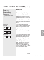
Control Function Descriptions
Process
Protection
Screens *
* Accessed from the Process
Screens.
SCREEN 16
Protection
Pro
tEc
When at screen 6, page 4-8, (or the process
screens), to access the process protection
screens, press the “Scroll” and “+” buttons
at the same time and hold for two seconds
from the Process screens. To get out of the
Process protection screens at any time, press
the “Scroll” and “-“ buttons at the same
time. (Refer to the flow charts on pages 4-4
and 4-5.)
This is the process protection header
screen. It indicates that all items below it
pertain to the process protection actual
temperature and alarms.
H.AI
This is the process protection high temperature alarm setpoint screen. If the actual
process protection temperature exceeds
this setpoint for the length of the process
protection high alarm delay (screen 19,
page 4-12), the process protection alarm
(A49) will trigger and the heater will shutdown. For example if the actual process
protection temperature exceeds 625°F
(330°C) for 10 seconds, the heater will
execute a shutdown alarm. The +/- buttons
can be used to change the setpoint.
(continued)
Operation l 4-11
4
Operation
250
SCREEN 18
625
Function
This screen shows the actual temperature
measured at the process protection RTD.
SCREEN 17
Act
(continued)
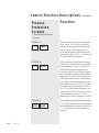
Control Function Descriptions
Process
Protection
Screens
(continued)
Function
* Accessed from the Process
Screens.
SCREEN 19
10
H.dL
SCREEN 20
325
d.AL
SCREEN 21
180
4-12
l Operation
d.dL
This is the process protection high alarm
delay screen. It is used to set the delay
time for the process protection high temperature alarm. If this time delay is
exceeded, the heater will execute a shutdown alarm (A49). The “+/-” buttons can
be used to change the setpoint.
This is the process differential alarm setpoint screen. If the actual process protection temperature (screen 17, page 4-11)
minus the actual process temperature
(screen 4, page 4-6) exceeds this setpoint
for the length of the process differential
alarm delay (screen 21), this alarm (A50)
will trigger and the heater will shutdown.
For example if the actual process protection temperature is 450°F (232.2°C) and
the actual process temperature is 124°F
(51.1°C) for 180 seconds (default) or the
time set on Screen 21, the heater will execute a shutdown alarm (A50). The “+/-”
buttons can be used to change the setpoint.
This is the process differential alarm delay
screen. This screen is used to change the
process differential alarm delay time. The
“+/-” buttons can be used to change the
setpoint.
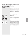
Control Function Descriptions
(continued)
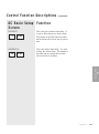
DC Resin Setup Function
Screen
To access the DC resin setup screens, press
the Scroll and “+” buttons at the same time
and hold for two seconds from the Process
Protection screens (screen 16). To get out
of the DC resin setup screens at any time,
press the Scroll and “-“ buttons at the same
time.
SCREEN 30
Set
bAc
SCREEN 31
250
20
ban
This shows the setback return band setting.
The value is used to determine when the
setback mode is disabled, once the dryer
has gone into the setback mode. This
example indicates a 20° band width, which
means when your hopper outlet temperature is 20° below your setpoint, the dryer
will come out of setback mode.
Operation l 4-13
4
SCREEN 32
This shows the actual return air temperature measured at the hopper outlet.
Operation
ret
This is the setback option setup screen. It
indicates that all items below it pertain to
the setback option.
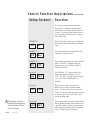
Control Function Descriptions
(continued)
DC Resin Setup Function
Screen
SCREEN 33
10
sls
SCREEN 34
Ldr
0
SCREEN 34A
Sbt
OFF
SCREEN 34B
SbL
4-14
l Operation
OFF
This is the setback load rate setpoint. (Not
available at this time.)
This is the load rate reading. (Not available
at this time.)
This is the setback on temperature. It turns
the setback on temperature option on or
off.
This controls the setback on load rate function. It turns the setback on load rate
option on or off. (Not available at this
time.)
Control Function Descriptions
(continued)
DC Resin Setup Function
Screen
SCREEN 35
2
P.dL
SCREEN 35A
10
A.dL
This is the process heater alarm delay. It
is used to delay the process heater alarm.
This number is the delay time in seconds
that an alarm will occur on loss of process
heat.
This is the airflow alarm delay. It is used
to delay the airflow alarm. This number is
the delay time in seconds that an alarm
will occur on loss of airflow.
4
Operation
Operation l 4-15
Control Function Descriptions
Setup Screens
(continued)
Function
To access the setup screens, press the
Scroll and “+” buttons at the same time
and hold for ten seconds from the Process
screens. To get out of the setup screens at
any time, press the Scroll and “-“ buttons
at the same time.
SCREEN 36
Set
uP
SCREEN 37
tyP
Res
SCREEN 38
Prt
ON
OFF
For HAD and “W” dryer models only.
This screen turns the setback “On” or
“Off”. The HTC is shipped with function
set to “On” if the setback option is
installed.
Screen 41
tSt
The setting on screen 42
should not be changed without the direction of Conair
Service Personnel.
4-16
l Operation
OFF
Screen 42
Ld.d
This screen indicates the hardware to the
controller. It will say “Res”.
This screen turns the process protection off
and on. The HTC is shipped with this
function set to “On” unless the HTC is
sold with an HAD.
Screen 39
Stb
This is the initial setup screen. It indicates
that all items below it pertain to the heater
setup.
OFF
This screen lets you access the Test
Mode.To access the test mode screens,
press "+" button when you are in the test
screen. To get out of the test mode screens
at any time, press the Scroll and "-" buttons at the same time.
This screen returns the control board to the
factory default settings (not necessarily for
a specific model). Conair does not recommend using this function unless instructed
to by a Conair Service Technician.
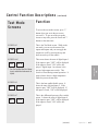
Control Function Descriptions
Te s t M o d e
Screens
(continued)
Function
To access the test mode screens, press "+"
button when you are in the test screen
(screen 41). To get out of the test mode
screens at any time, press the Scroll and "-"
buttons at the same time.
SCREEN 43
tE
St
SCREEN 44 *
in.1
OFF
in.2
ON
This is the heat enable/disable screen. It
shows the state of digital input 2. If the
input is open, "OFF" will be displayed. If
the input is closed, "ON" will be displayed.
ON
This is the differential pressure (flow switch)
screen. It shows the state of digital input 4.
If the input is open, "OFF" will be displayed.
If the input is closed, "ON" will be displayed.
SCREEN 47
in.4
(continued)
Operation l 4-17
4
SCREEN 45
This screen shows the state of digital input 1.
If the input is open, "OFF" will be displayed.
If the input is closed, "ON" will be displayed. Digital input 1 on a heater is the
process high temperature switch. This
switch is closed during normal operation. It
opens when it detects a high temperature
inside the process heater tube.
Operation
* See the supplied electrical drawings to associate instruments to
inputs.
This is the Test Mode screen. While in the
test mode, you can see the status of the
inputs and outputs and you can toggle the
outputs on or off by pressing the up and
down arrow keys on the control.
Control Function Descriptions
Te s t M o d e
Screens *
(continued)
Function
* Outputs 1, 2, and 4 are not used
in the HTC.
SCREEN 50
ou.3
OFF
SCREEN 52
ou.5
OFF
SCREEN 53
ou.6
4-18
l Operation
OFF
This is the output 3 screen. Press the "+"
key to jog output 3. Output 3 on a heater
is the process heater solid-state relay signal. Pressing the "+" key will cause the
process solid-state relays to fire. You can
observe the solid-state relay LED to check
this output. Since the isolation contactor is
open, the heater does not come on because
it does not have power.
This is the output 5 screen. Press the "+"
key to jog output 5. Output 5 on a heater
is the process heater power isolation contactor signal. Pressing the "+" key will
cause the isolation contactor to close.
Watch the isolation contactor pull in to
check this output. Since the solid-state
relays are not on, the heaters does not
come on because they do not have power.
This is the output 6 screen. Press the "+"
key to jog output 6. Output 6 on a heater
is the alarm horn. Pressing the "+" key
will cause the alarm horn to sound.
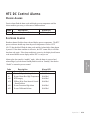
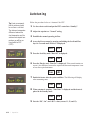
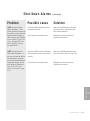
HTC DC Control Alarms
PASSIVE ALARMS
Passive alarms flash the alarm code and display process temperature until the
alarm condition goes away, or it becomes a shutdown alarm.
Code
P1
Description
Process Temperature Deviation
Alarm LED
Blinking Red
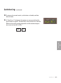
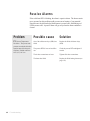
SHUTDOWN ALARMS
Shutdown alarms flash the alarm code and display process temperature. The HTC
process air heater should stop when the process temperature is below 150°F
(65.6°C) but should still flash the alarm code until the Acknowledge Alarm button
is pressed. If the alarm condition is still active, the HTC cannot start, it will flash
the alarm code again. If the alarm condition is not active, the display should return
to the normal default screen display and the HTC is ready to run.
A49
A50
Description
Process High Temperature
Process Temperature Loop Break
Process Heater Box High Temperature
RTD Integrity
EEProm Write Error-Internal Control
Board Problem
Process Protection High Alarm
Process Differential Alarm
Alarm LED
Solid Red
Solid Red
Solid Red
Solid Red
Solid Red
Solid Red
Solid Red
Operation l 4-19
4
Code
A1
A2
A3
A10
A39
Operation
Alarms place the control in “standby” mode. After the alarm is corrected and
acknowledged, cycle the heater Standby/Enable switch to “Standby” then back to
“Enable” to restart the process control.
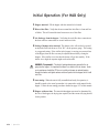
Initial Operation (For HAD Only)
1 Hopper material: Fill the hopper with the material to be heated.
2 Blower inlet filter: Verify that the area around the inlet filter is clean and free
of debris. This will extend the time between service of this filter.
3 Air discharge from the hopper: Verify that the sock filter hose connection to
the dust collector connections are secure and do not leak.
4 Setting of damper after material: The damper valve will need to be opened
to adjust the flow back down to 20 in. W.C. on the pressure gauge. This setting
is a suggested setting. If the airflow in the hopper is carrying over material out
of the hopper, then the flow rate may be adjusted downward by closing the
damper. If the airflow is too low then the heater will go into stand by. If the
airflow is too high, the setpoint might not be achievable.
WARNING: Fire potential - The electric heating elements are exposed to the air
going into the hopper. It is important that there is no debris in this air stream. Under
no circumstances should the HTC be run in a dirty air stream as material passing
through the heater could ignite embers and shoot sparks into the hopper, which could
catch fire.
5 Auto tuning: When the unit is fully assembled and ready for operation, it
should be tuned to the actual system that it is connected to with material in the
hopper. Follow the auto tuning procedure detailed on page 4-22 of this manual.
6 Hopper residence time: The material throughput rate must be determined by
the size of the hopper, the drying time required, and the extent of drying desired
for the product.
4-20
l Operation
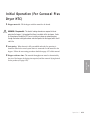
Initial Operation (For Carousel Plus
Dryer HTC)
1 Hopper material: Fill the hopper with the material to be heated.
WARNING: Fire potential - The electric heating elements are exposed to the air
going into the hopper. It is important that there is no debris in this air stream. Under
no circumstances should the HTC be run in a dirty air stream as material passing
through the heater could ignite embers and shoot sparks into the hopper, which could
catch fire.
2 Auto tuning: When the unit is fully assembled and ready for operation, it
should be tuned to the actual system that it is connected to with material in the
hopper. Follow the auto tuning procedure detailed on page 4-22 of this manual.
3 Hopper residence time: The material throughput rate must be determined by
the size of the hopper, the drying time required, and the extent of drying desired
for the product (see page 4-20).
4
Operation
Operation l 4-21
Autotuning
✒ Tip: Conair recommends
that the autotune should
be run from a cold start.
The minimum temperature
difference between the
start temperature and the
autotune and setpoint temperature you will be running should be 50ºC
(122ºF).
Follow the procedure below to “Autotune” the HTC.
1 Use the selector switch and put the HTC control into “Standby”.
2 Adjust the setpoint to a “Normal” setting.
3 Establish the normal operating air flow.
4 Access the Process menu by pressing and holding the Scroll and Plus
keys for 2 seconds until “Process” is displayed.
Pro
cES
5 Press the Scroll key until “Tune Off” is displayed.
tun
OFF
6 Press the Plus key and “Tune Set” is displayed. If the control remains on
screen 6, the difference between the setpoint and the actual temperature is not
at least the required minimum.
tun
SEt
7 Enable the heater after the system stabilizes. The following will display
when autotuning starts.
tun
Hr.u
8 When autotune is complete, “Tune Done” is displayed and the heater is
placed in the Standby mode.
tun
don
9 Note the “Pb”, “int”, and “dEr” values (screens 11, 12, and 13).
4-22
l Operation
Autotuning
(continued)
10 To return to the normal control, cycle the heater to Standby and then
back to Enable.
11 If “Tune Error 1” is displayed, the autotune was not successful and the
process must be repeated. The most likely reason for this error is that the
difference between the starting temperature and the autotune temperature was not at least 50ºC (122ºF).
tun
Er.1
4
Operation
Operation l 4-23
N o r m a l O p e r a t i o n To S t a r t H e a t i n g
1 Determine what the HTC’s setpoint must be for your process and material.
2 Make sure there is material in the hopper.
3 Start the dryer or process blower to begin air flow. Set the proper flow on
ON
the blower if equipped.
OFF
4 Turn on the main power to the HTC. Make sure the HTC’s disconnect dial
O
is in the ON position. This powers up the control and the display lights will
illuminate.
5 Set the drying temperature. Press the Adjust Setpoint ▲ or t buttons to
select the temperature.
Startup /
Shutdown
Heaters
Enable
Standby
Setpoint Adjust
Buttons
For Startup:
1. With heaters in
Standby, turn on
blower or dryer.
2. Enable heaters.
For Shutdown:
1. Switch heaters to
Standby.
2. Wait 60 seconds
before turning off
blower or dryer.
7 Turn the heater switch to “Enable” to start heating.
4-24
l Operation
N o r m a l O p e r a t i o n To S t o p H e a t i n g
Startup /
Shutdown
1 Turn the heater to “Standby”.
Heaters
Enable
IMPORTANT: Always turn off the HTC BEFORE the dryer or process blower.
Standby
For Startup:
1. With heaters in
Standby, turn on
blower or dryer.
2. Enable heaters.
For Shutdown:
2 Allow the HTC to cool to below 100°F (37.8°C).
1. Switch heaters to
Standby.
2. Wait 60 seconds
before turning off
blower or dryer.
3 Turn off the blower or dryer.
4 Be sure to disconnect and lockout the main power if you have stopped the
HTC to perform maintenance or repair.
Operation l 4-25
4
Operation
CAUTION: Improper shut down can cause damage to your heater.
4-26
l Operation
SECTION
5
Maintenance
Preventative maintenance checklist . . . . . . . 5-2
5
Maintenance
Maintenance l 5-1
Preventative Maintenance
Checklist
The HTC process air heater requires little maintenance. We recommend the following maintenance schedule and tasks.
• Whenever you change material or process
❒ Change the HTC setpoint if it must be changed.
• Daily or weekly as needed
❒ Inspect the inlet and outlet hoses.
Tighten the hose clamps if loose. Replace the hose if worn or damaged.
❒ Inspect the filter (if equipped).
Clean or replace the filter as necessary.
• Monthly or as often as needed
❒ Inspect the main power wires, heater wires and conduit, and RTD
probe wires for damage and wear.
Replace any damaged or worn wire or conduit.
❒ Check for any damage to the control panel.
Replace if damaged.
❒ Check for damage to the heater box.
Replace if damaged.
❒ Clean dirt from exterior surfaces with a cloth dampened with water.
5-2 l Maintenance
SECTION
6
Tr o u b l e s h o o t i n g
Before beginning . . . . . . . . . . . . . . . . . . . . 6-2
A few words of caution
. . . . . . . . . . . . . . 6-3
DIAGNOSTICS
How to identify the cause of a problem . . . . 6-4
Shut down alarms . . . . . . . . . . . . . . . . . . 6-5
Pa s s i v e a l a r m s
. . . . . . . . . . . . . . . . . . . . 6-8
R E PA I R
Replacing fuses . . . . . . . . . . . . . . . . . . . . 6-9
Checking heater solid state relays . . . . . . . 6-10
Checking or replacing temperature
Replacing the heating elements
. . . . . . . . 6-12
Replacing the air flow differential
pressure switch . . . . . . . . . . . . . . . . . 6-14
Tr o u b l e s h o o t i n g l 6 - 1
6
Troubleshooting
sensors . . . . . . . . . . . . . . . . . . . . . . 6-11
Before Beginning
You can avoid most problems by following the recommended installation and
maintenance procedures outlined in this User Guide. If you do have a problem,
this section will help you determine what caused it and how to fix it.
Before you start disassembling the HTC process air heater be sure to:
❏ Diagnose causes from the control panel.
1
Press the Acknowledge Alarm button to silence the alarm.
2
3
4
Address the alarm message and fix the problem.
Move the heater switch from Enable to Standby.
Cycle the heater switch from Standby to Enable to restart normal control. If the alarm reappears the problem was not fixed.
If the alarm is a passive alarm you will see P in the screen title display.
If the alarm is a shut down alarm you will see A in the screen title
display.
Startup /
Shutdown
Heaters
Enable
Standby
For Startup:
1. With heaters in
Standby, turn on
blower or dryer.
2. Enable heaters.
For Shutdown:
1. Switch heaters to
Standby.
2. Wait 60 seconds
before turning off
blower or dryer.
Scroll
Button
❏ Diagnose causes from the control panel.
You can locate any problem from the front of the heater.
6 - 2 l Tr o u b l e s h o o t i n g
Acknowledge
Alarm Button
Before Beginning
(continued)
See warnings
below. Open the
control center to
check fuses and
heater contactors.
❏ Find the wiring and equipment diagrams that were shipped with your heater. These diagrams are the best reference for correcting a problem. The diagrams also will note any custom
features, such as special wiring or alarm capabilities, not covered in this User Guide.
A Fe w Wo r d s o f C a u t i o n
The HTC process air heater is equipped with numerous safety devices. Do
not remove or disable them. Improper corrective action can lead to hazardous
conditions and should never be attempted to sustain production.
WARNING: Only qualified service personnel should examine and correct
problems that require opening the dryer’s control center or using electrical wires to diagnose the cause.
WARNING: High voltage. Always stop the HTC process air heater, disconnect and lock out the main power source before troubleshooting or performing repairs.
Tr o u b l e s h o o t i n g l 6 - 3
6
Troubleshooting
CAUTION: Hot surfaces. Always protect yourself from hot surfaces inside
and outside of the heater.
How to Identify the Cause of a
Problem
Most heater malfunctions are indicated by an illuminated Alarm light on the HTC
process air heater control panel.
A problem can trigger two types of alarms:
• Shut Down: The heater has automatically shut down because it detected a
serious problem that could damage your material or dryer.
• Passive: The heater continues to operate, but warns of a problem that could
prevent correct heating of your material. If ignored, this problem could lead to
a condition that will shut down the dryer.
Startup /
Shutdown
Heaters
Enable
Standby
For Startup:
1. With heaters in
Standby, turn on
blower or dryer.
2. Enable heaters.
Alarm Light
For Shutdown:
1. Switch heaters to
Standby.
2. Wait 60 seconds
before turning off
blower or dryer.
Acknowledge Alarm
Button
When the alarm light is displayed:
1 Press the Acknowledge Alarm button to silence the alarm (see page
4-2).
2 Find the error message in the diagnostics table of this Troubleshooting
section.
3 Cycle the heater switch from Enable to Standby and then back to
Enable to clear and restart normal control. If the alarm reappears, the
problem was not fixed.
6 - 4 l Tr o u b l e s h o o t i n g
Shut Down Alarms
If the red Acknowledge Alarm LED is solid, the alarm is a shutdown alarm.
The heater will shutdown automatically to prevent damage to the equipment
or personnel.
Possible cause
Solution
A1 Process High
Temperature – If the process
temperature exceeds the
process high temperature setpoint, it shuts down the dryer.
Defaults are set to 385°F
(196.1°C) for 20 sec. for CP
HTCs, and 360°F (182.2°C)
for 20 sec. for HADs.
The process high temperature is not at
least 10°F (5.6°C) above the setpoint.
Increase the process high temperature.
The RTD temperature probe is not
installed correctly.
Make sure the RTD temperature probe
tip is in the center of the hopper inlet
tube.
The air lines are restricted or loose.
Straighten any crimps in the hoses.
Tighten any loose hoses.
SSR has failed.
Replace the SSR.
Output on the board has failed.
Replace the board.
Process RTD is loose or has fallen out.
Check the process RTD and tighten if
needed.
The process heater has failed.
Check the heater fuses, and resistance
across each leg of the process heater.
The air lines are restricted or loose.
Straighten any crimps in the hoses.
Tighten any loose hoses.
Output on the board failed “Open”.
Replace the board.
Drying or setback setpoint is too low.
Adjust the setpoint.
A2
Process Temperature
Loop Break – If the process
temperature is outside of the
operator entered deviation,
alarm band (see Process High
Temperature Deviation passive
alarm) and the process temperature is not moving
towards the setpoint at a rate
greater than specified. It shuts
down the dryer. Defaults are
set at 3°F (1.7°C) over 20 sec.
(continued)
Tr o u b l e s h o o t i n g l 6 - 5
6
Add additional cooling, either a precooler or an aftercooler, to the circuit.
Troubleshooting
Problem
Shut Down Alarms
(continued)
Problem
Possible cause
Solution
A3
There is an air flow blockage or loose
hoses.
Remove the blockage.
Process Heater High
Temperature – The snap switch
in the process heater tube
opens due to excessive temperature.
Tighten any loose hoses.
The isolation contactor failed in the
closed position.
Replace the isolation contactor.
The heater solid state relays (SSRs)
failed.
Replace the failed heater solid state
relays (SSRs).
No air flow or the airflow is reversed.
Turn on the blower.
Reverse the connection points of the
hoses.
Check the operation of the differential
pressure switch.
A10
RTD Integrity – If a
RTD is faulty.
A39
EEProm Write Error.
6 - 6 l Tr o u b l e s h o o t i n g
The connection in the electrical enclosure for the RTD is loose.
Check the RTD plug connection and
tighten if needed.
The connection of the RTD plug on the
control board is loose.
Check the plug connection and tighten if
needed.
One of the RTDs has failed.
Replace the RTD.
The RTD is enabled but wired incorrectly.
Move the wires to the proper terminals
(see the wiring diagrams supplied with
the unit).
Internal control board problem.
Replace the control board.
Shut Down Alarms
(continued)
Problem
Possible cause
Solution
A49
Process Protection
High Temperature – If the
process protection temperature
exceeds the process protection
high temperature setpoint, it
shuts down the dryer. Defaults
are set to 600°F (315.6°C) for
10 sec. for larger HTCs and
400°F (204.4°C) for 10 sec.
for smaller HTCs.
The Process RTD temperature probe is
not installed correctly.
Make sure the RTD temperature probe
tip is in the center of the hopper inlet
tube or heater manifold.
The air lines are restricted or loose.
Straighten any crimps in the hoses.
Tighten any loose hoses.
A50
The Process RTD or Process Protection
RTD temperature probe is not installed
correctly.
Make sure the RTD temperature probe
tip is in the heater outlet (see page 3-10).
The air lines are restricted or loose.
Straighten any crimps in the hoses.
Tighten any loose hoses.
Process Protection
Differential Temperature – If
the process protection differential temperature exceeds the
process protection differential
temperature setpoint, it shuts
down the dryer. Defaults are
set to 175°F (325°C) for
180 sec. (see screen 21, page
4-12).
6
Troubleshooting
Tr o u b l e s h o o t i n g l 6 - 7
Pa s s i v e A l a r m s
If the red Alarm LED is blinking, the alarm is a passive alarm. The heater continues to operate, but this problem could prevent correct heating of your material.
Note that once the Acknowledge Alarm button is pressed once, the blinking red
LED becomes solid. A passive alarm will go away when the alarm condition is
cleared.
Problem
Possible cause
Solution
P1
One of the solid state relays (SSRs) has
failed.
Replace the failed solid state relays
(SSR).
The process RTD is loose or has fallen
out.
Check the process RTD and tighten if
needed.
The air hose connections are loose.
Tighten all air hose connections.
The heater has failed.
Replace the failed heating element (see
page 6-12).
Process Temperature
Deviation – The process temperature exceeds the deviation
band as entered for the specified time. Default values are
10°F (6°C) for 5 sec.
6 - 8 l Tr o u b l e s h o o t i n g
Replacing Fuses
ON
OFF
1 Disconnect and lockout the main power supply.
O
2 Open the control center.
Fuse Blocks
To locate the appropriate fuse
and replacement part, refer to
the wiring diagrams that
came with your HTC.
IMPORTANT: Always refer
to the wiring diagrams that
came with your heater to
locate specific electrical
components. Illustrations in
the User Guide are intended
to be representative only.
3 Check the fuse. If necessary, pull the fuse out and replace it with a fuse of the
same type and rating.
6
Troubleshooting
Tr o u b l e s h o o t i n g l 6 - 9
Checking Heater Solid State Relays
ON
2 Open the control center door.
O
OFF
1 Disconnect and lockout the main power supply.
3 Locate the process solid state relays (SSRs). Refer to the wiring diagrams that
came with your heater.
4 Check the resistance using an ohmmeter.
IMPORTANT: Always refer
to the wiring diagrams that
came with your heater to
locate specific electrical
components. Illustrations in
the User Guide are intended
to be representative only.
6 - 1 0 l Tr o u b l e s h o o t i n g
Solid state relays
Check the resistance between
the terminal screws. If ohms
equal zero, replace the relays.
Terminal Screws
C h e c k i n g o r R e p l a c i n g Te m p e r a t u r e
Sensors
The HTC process air heater uses RTD sensors to monitor the process temperature
in the hopper inlet, the setback temperature in the hopper outlet, and the process
protection temperature in the heater outlet.
IMPORTANT: Always refer
to the wiring diagrams
that came with your
heater to locate specific
electrical components.
Illustrations in the User
Guide are intended to be
representative only.
Typical location of the
Process RTD
at the hopper
inlet.
ON
O
1 Disconnect and lockout the main power supply.
OFF
To check or replace an RTD sensors:
2 Locate the RTD sensors.
3 Check the sensor positions and conditions. Temperature readings will be
4 To check with ohm meter, measure the resistance across the RTDs. The
resistance should be approximately 110 ohm at room temperature.
5 Replace the sensor, if necessary.
Tr o u b l e s h o o t i n g l 6 - 1 1
6
Troubleshooting
incorrect if the sensors are touching the wall of an air hose or pipe or if the sensor or wiring is damaged. The tip of the sensor should be centered within the
air hose or pipe. Sensor wires should be attached to the appropriate connection
points on the heater’s control center.
Replacing the Heating Elements
ON
O
OFF
1 Disconnect and lockout the main power.
2 Gain access to the heating elements by removing screws that
secure the heating element cover to the enclosure.
3 Remove the heating element cover by tilting
the top away from the enclosure slightly, then
lifting the cover up and away from the enclosure.
IMPORTANT: Always refer
to the wiring diagrams
that came with your
heater to locate specific
electrical components.
Illustrations in the User
Guide are intended to be
representative only.
4 Refer to the “Testing the Installation” section
(page 3-13) and determine which heater(s) is
not functioning.
5 Remove the screws securing the electrical
cover plate to the heating element enclosure.
Remove the electrical cover plate.
Screws to Remove
- Large Heaters
6 Note the connection points then disconnect the heating element leads from
the terminals on the terminal block.
Heater
Wires
Heater
Connection
Junction Box
6 - 1 2 l Tr o u b l e s h o o t i n g
Replacing the Heating
E l e m e n t s (continued)
✐
Note: For larger units (above 60
kW), it may be necessary to
remove the front heaters to
access the rear heaters.
Clamps
to
insulated hose to the outlet of the heatRemove
ing element. Remove the hose.
7 Remove the hose clamp securing the
8 Remove the hose clamps securing the
heating element to the heater inlet.
9 Remove the internal hose clamp.
10 Lift the heating element out of the enclosure.
11 Slide the insulation off the heater, or make a cut the entire length of
the insulation sleeve to aid removal.
12 Check the ID mark on the side of the heating element for kW rating
Clamp
and voltage. The ID mark is on the outside of the tube near the end with the
lead wires. Make sure the kW and voltage is the same as the replacement
heating element.
13 Slide the original insulation over the new heater or, if the insulation was
cut for removal, wrap the cut insulation sleeve around the new heater and
secure it with duct tape.
14 Set the new heating element into the enclosure. Secure the heating element to the heater inlet with the original three (3) hose clamps.
Secure the hose with the original hose clamp.
16 Route the heating element leads to the terminal block. Connect the heating element leads to the original terminals on the terminal block. Reinstall
the electrical cover plate.
17 Reinstall the heating element cover on the enclosure.
18 Test the system to insure that the new heating element is functioning correctly (see Page 3-13, Step 3).
Tr o u b l e s h o o t i n g l 6 - 1 3
6
Troubleshooting
15 Connect the insulated outlet hose the the outlet of the heating element.
Replacing the Air Flow Differential
Pressure Switch
If the air flow differential pressure switch fails to detect the pressure drop between
the heater inlet and outlet, it should be replaced.
1 Stop the heater, disconnect and lockout the main power.
O
OFF
ON
2 Gain access to the heating elements by removing screws that
secure the heating element cover to the enclosure.
3 Remove the heating element cover by tilting
IMPORTANT: Always refer
to the wiring diagrams
that came with your
heater to locate specific
electrical components.
Illustrations in the User
Guide are intended to be
representative only.
the top away from the enclosure slightly, then
lifting the cover up and away from the enclosure.
4 Note their location then remove the two
wires connected to the pressure switch.
5 Note their locations then disconnect the
hose coming from the heater outlet from
the low pressure side of the switch and the
hose coming from the heater inlet from
the high pressure side of the switch.
6 - 1 4 l Tr o u b l e s h o o t i n g
Replacing the Air Flow Differential
P r e s s u r e S w i t c h (continued)
6 Remove the mounting hardware securing the
pressure switch to the heating element enclosure.
7 Align the new pressure switch with the mounting holes and secure it to the heating enclosure
using the original mounting hardware.
8 Connect the hose coming from the heater outlet
to the low pressure side of the switch and the
hose coming from the heater inlet to the high
pressure side of the switch.
9 Connect the two wires to their original location on the pressure switch.
10 Test the system to insure that the new air flow differential switch is detecting the pressure drop between the heater inlet and outlet.
11 Reinstall the heating element cover on the enclosure.
12 Connect the hose coming from the heater outlet to the low pressure side
of the switch and the hose coming from the heater inlet to the high pressure side of the switch.
13 Connect the two wires to their original location on the pressure switch.
14 Test the system to insure that the new air flow differential switch is detecting the pressure drop between the heater inlet and outlet.
6
Troubleshooting
Tr o u b l e s h o o t i n g l 6 - 1 5
6 - 1 6 l Tr o u b l e s h o o t i n g
We ’ r e H e r e t o H e l p
Conair has made the largest investment in customer support in the plastics industry. Our service experts are available to help with any problem you might have
installing and operating your equipment. Your Conair sales representative also
can help analyze the nature of your problem, assuring that it did not result from
misapplication or improper use.
Additional manuals and prints for
your Conair equipment may be
ordered through the Customer
Service or Parts Department for a
nominal fee, or visit the product
section of the Conair website
www.conairnet.com.
How to Contact Customer Service
To contact Customer Service personnel, call:
✐
NOTE: Normal operating hours are 8:00 AM - 5:00 PM. After hours emergency
service is available at the same phone number.
From outside the United States, call: 814-437-6861
You can commission Conair service personnel to provide on-site service by contacting the Customer Service Department. Standard rates include an on-site hourly
rate, with a one-day minimum plus expenses.
B e f o r e Yo u C a l l . . .
If you do have a problem, please complete the following checklist before
calling Conair:
❒ Make sure you have all model, control type from the serial tag, and parts list
numbers for your particular equipment. Service personnel will need this information to assist you.
❒ Make sure power is supplied to the equipment.
❒ Make sure that all connectors and wires within and between control systems
and related components have been installed correctly.
❒ Check the troubleshooting guide of this manual for a solution.
❒ Thoroughly examine the instruction manual(s) for associated equipment, especially controls. Each manual may have its own troubleshooting guide to help you.
❒ Check that the equipment has been operated as described in this manual.
❒ Check accompanying schematic drawings for information on special considerations.
Appendix l A-1
Equipment Guarantee
Conair guarantees the machinery and equipment on this order, for a period as
defined in the quotation from date of shipment, against defects in material and
workmanship under the normal use and service for which it was recommended
(except for parts that are typically replaced after normal usage, such as filters,
liner plates, etc.). Conair’s guarantee is limited to replacing, at our option, the part
or parts determined by us to be defective after examination. The customer assumes
the cost of transportation of the part or parts to and from the factory.
Pe r f o r m a n c e Wa r r a n t y
Conair warrants that this equipment will perform at or above the ratings stated in
specific quotations covering the equipment or as detailed in engineering specifications, provided the equipment is applied, installed, operated and maintained in the
recommended manner as outlined in our quotation or specifications.
Should performance not meet warranted levels, Conair at its discretion will
exercise one of the following options:
• Inspect the equipment and perform alterations or adjustments to satisfy
performance claims. (Charges for such inspections and corrections will be
waived unless failure to meet warranty is due to misapplication, improper
installation, poor maintenance practices or improper operation.)
• Replace the original equipment with other Conair equipment that will meet
original performance claims at no extra cost to the customer.
• Refund the invoiced cost to the customer. Credit is subject to prior notice by the
customer at which time a Return Goods Authorization Number (RGA) will be
issued by Conair’s Service Department. Returned equipment must be well crated
and in proper operating condition, including all parts. Returns must be prepaid.
Purchaser must notify Conair in writing of any claim and provide a customer receipt
and other evidence that a claim is being made.
Wa r r a n t y L i m i t a t i o n s
Except for the Equipment Guarantee and Performance Warranty stated
above, Conair disclaims all other warranties with respect to the equipment,
express or implied, arising by operation of law, course of dealing, usage of
trade or otherwise, including but not limited to the implied warranties of
merchantability and fitness for a particular purpose.
A-2 l Appendix
Blower Installation and
Maintenance
✐
Note: This addendum
applies only if you have
This addendum will assist you in installing and maintaining your HAD blower.
By following the general instructions presented, you will prolong the life of the
equipment, while preventing unexpected downtime.
purchased a Conair Hot
Air Dryer (HAD).
Receiving
All shipments are F.O.B. It is, therefore, in the interest of the buyer to carefully
inspect all shipments before they are accepted from the freight carrier. Upon
delivery, be sure that all items listed on the bill of lading and packing list
(inserted in the plastic envelope attached to the shipment) have been received.
Partial shipments are sometimes made.
The units are skidded, boxed, or crated to fully comply with rail or trucking
requirements for shipment. Accessories are sometimes shipped separately due
to handling space requirements.
Although all equipment is carefully inspected and prepared for shipment at the
factory, damage to the fan and/or drive parts may occur due to rough handling
during shipment.
Any shortage, breakage, or damage noticed at time of delivery should be indicated to the carrier's representative. Damage noticed after delivery should be
reported to the carrier at once. Request their inspection of the shipment and fill
out a concealed damage inspection report.
Addendum l
AD-1
Handling
Small units should be handled carefully and lifted only by the base, never by
the shaft, coupling, motor, or housing. Large units should be lifted by the base
or by the lifting eyes. Precautions should be taken to avoid dropping or jarring
the equipment as this can cause damage to the shaft or wheel, which is not visibly noticeable, but can cause vibration problems.
Installation
✒ TIP: Extended Storage - Units
that will be held in storage for a
period of up to two (2) years
should have special provisions so
operation-readiness can be
Fans and motors should be mounted on structurally sound foundations.
Concrete is the best, however, other types designed properly are acceptable.
Equipment should be leveled on the foundation and shimmed or grouted in
place. This will prevent putting the fan structure into a bind by bolting it down
on an uneven surface.
maintained. Motors should be
equipped with internal space
heaters kept on continuously.
Units should be crated and covered with polyethylene film. In
addition, impellers should be
hand-rotated once a month. For
best results, keep the units sheltered in a cool, dry location.
AD-2 l Addendum
As a general rule, if vibration isolators are used, the fan should first be bolted to
a structural steel base and the isolation takes place between the structural steel
base and the foundation. This prevents the fan base from floating due to uneven
weight distribution and/or drive forces when mounted directly to vibration isolators.
Wiring the Starter
The electrical connection consists of bringing power to the starter on the blower
assembly. The incoming power should match the rated nameplate power
required on the serial tag on the blower. This power should be clean and have
a voltage variation of no more that +/- 5% of the nameplate voltage.
IMPORTANT: Always refer to the
wiring diagrams that came with
your blower before making electrical connections.
CAUTION: Always disconnect and lock out the main power sources before making electrical connections. Electrical connections should be made only by qualified personnel.
CAUTION: Check the disconnect with a volt meter to insure that the power is off.
1 Disconnect and lock out the main power sources before making electrical
connections. Electrical connections should be made only by qualified personnel.
2 Remove the cover from the main power control box on the blower assembly.
3 Route the main power cable through the power control box. Secure the
power cable with a rubber compression fitting or strain relief, or use conduit.
Verify that the incoming power is securely attached to the blower assembly and
there is no strain on the incoming power wires.
4 Connect the power wires to the three terminals on the upper side of the starter
power disconnect.
5 Connect the ground wire to the ground lug.
Power Wires
(Black- Customer
Supplied)
✐
Ground Wire
(Green - Customer
Supplied)
Note: The connections at the starter
should be made with properly sized
conductors and properly protected
with appropriate conduit. The routing should be neat and away from
potential mechanical damage. The
terminations should be landed on the
terminals on the starter. These terminations should be regularly
checked to prevent loosening and
shorting to ground.
Addendum l
AD-3
Before Start-up
Before start-up, the following should be verified.
1 Fasteners - All foundation bolts, wheel hub setscrews, wheel locking bolts,
and bearing locking collars must be tight.
2 Bearings - Check the bearings and make certain they are properly lubricated.
3 Fan Wheel - Turn over the rotating assembly by hand to insure that it runs
free and does not bind or strike the fan housing. If the wheel strikes the
housing, the wheel may have to be moved on the shaft.
4 Motor - Check the electrical wiring to the motor. The current characteristics
IMPORTANT: Always refer to the
wiring diagrams that came with
your blower before checking electrical connections.
of the supply line must agree with the motor nameplate rating. The motor
should be wired and fused in accordance with the National Electric Code
(NEC) and local codes.
5 Ducts - Duct connections from the fan to the duct work must not be distorted. Ducts should never be supported by the fan. All duct joints should be
sealed to prevent air leaks. All debris should be removed from the ductwork
and the fan.
6 Resistance Check - Check the resistance leg to leg and leg to ground to make
sure that the starter is wired correctly. The three legs should have equal resistance +/- 5%. The resistance to ground should be 20 megohms or higher.
AD-4 l Addendum
Start-up
1 Using the Start/Stop button, ”Jog" the motor
to check for proper wheel rotation. The motor
should be started in accordance with the manufacturer's recommendations. Arrows on the fan indicate the proper direction of rotation and airflow.
Start/Stop
Button
2 Throttle the blower discharge
damper ¼ open. (It is shown
fully open in this photo.)
Discharge
Damper
Fully Closed
Fully Open
3 The fan may now be brought
up to speed. Watch for anything
unusual such as vibration, overheating of bearings and motor,
etc.
4 Throttle the discharge damper until the pressure is 15-20" WC.
5 Check the motor amperage against the nameplate amperage to
make sure the motor is not overloading.
Addendum l
AD-5
B a l a n c e a n d Vi b r a t i o n
All fan impellers are dynamically balanced prior to installation in the fan
assembly. After assembly, fans supplied with motors are test run and fine-tune
balanced to reduce vibration levels to acceptable limits as shown in table below
(from AMCA Standard 204-96).
After field installation, fans will need to be checked prior to commissioning to
assure that the vibration levels do not change significantly from those achieved
at the factory. It is recommended that the velocity values in the table below are
not exceeded by more than 10% when field installed.
Fan Application Category
BV-3
Rigid Mounted
mm/sec (in./sec)
3.8
(0.15)
Flexible Mounted
mm/sec (in./sec)
5.1
(0.20)
The installed vibration level of any fan is not solely dependent on the balance
grade. Installation factors such as the mass and stiffness of the supporting system will influence the "as installed" vibration level (refer to AMCA Publication
202, Troubleshooting).
AD-6 l Addendum
General Maintenance
1 Inspection - A definite time schedule for inspecting all rotating parts and
accessories should be established. The frequency of inspection depends on
the severity of operation and the locality. Inspections might be weekly at
first in order to set up the schedule.
2 Alignment - The shaft must not be cocked in the bearings. Misalignment
can cause overheating, wear to dust seals, bearing failure, and vibration.
3 Hardware - Check the tightness of all bolts and setscrews.
4 Lubrication - Check the fan and motor bearings and add lubricant if necessary. Be careful not to over grease as this can damage bearing seals.
5 Air Flow - Make sure there is no debris or unnecessary obstructions to airflow in the outlet or inlet ductwork.
6 Bearings - On high-speed fans, the bearings tend to run hot. Therefore, do
not replace a bearing because it feels hot to the touch. Place a pyrometer or
contact thermometer against the pillow block and check the temperature.
Pillow block and flange mount bearings can have housing surface temperatures of 200°F (93°C) before the cause of overheating should be investigated.
7 Wheel - Inspect the wheel blades for accumulation of dust and dirt. Clean
thoroughly with a stream of water jet, compressed air, or a wire brush. This
will help prevent an unbalanced condition. If the blades are aluminum, be
careful not to damage them. Cover the bearings so water does not enter the
pillow block. The wheel should have proper clearances to prevent the blades
from striking the housing. Make sure the wheel is rotating in the proper
direction. Never run the fan at a higher speed or temperature than is shown
on the fan nameplate. Contact Conair with any questions.
CAUTION: Wear eye protection. If you use compressed air to clean the equipment, you must wear eye protection and observe all OSHA and other safety
regulations pertaining to the use of compressed air.
Addendum l
AD-7
Fa n B e a r i n g M a i n t e n a n c e
For most applications, a lithium base grease (such as Mobilith AW2) conforming to a NLGI Grade 2 consistency should be used. This type of grease inhibits
rust, is water resistant, and has a temperature range of -30 to 200°F (-34.3 to
93.3°C), with intermittent highs of 250°F (121°C). For extreme duty and higher temperature applications, use Mobilith SHC220 synthetic hydrocarbon
grease.
When greasing bearings, it is important not to over-grease. This is especially
true if the bearings are equipped with extended grease lines and the bearings are
not visible. In this case, more bearing failures occur due to over-greasing than
under-greasing. It is best to give the bearing just one "shot" of grease periodically if the bearings are not visible. When the bearings are visible, pump in
grease until a small bead of grease forms around the bearing seals. It is very
important that fan bearing greasing take place while the fan is operating.
CAUTION: Caution should be taken while working on and near rotating equipment to avoid personal injury.
AD-8 l Addendum
Motor Maintenance
Lubricate the motor bearings to the manufacturer's recommendations.
Lubrication recommendations are included with the packet attached to the fan.
Should this packet be missing, the following will apply:
Integral Horsepower Ball Bearings Motors: Motors having pipe plugs or
grease fittings should be re-lubricated while warm and at standstill. Replace
one (1) pipe plug on each end shield with a grease fitting. Remove the other
plug for grease relief. On low pressure, grease, run, and lubricate until the new
grease appears at the grease relief. Allow the motor to run for ten (10) minutes
to expel any excess grease. Replace the pipe plugs. Motors not having pipe
plugs or grease fittings can be re-lubricated by removing the end shield, cleaning the grease cavity, and refilling three-fourths or circumference of the cavity.
Recommended Re-lubrication Intervals (General Guide Only)
Horse Power
Range
Standard Duty
8 hr/day
1.5 - 7.5
10 - 40
50 - 150
5 yrs.
3 yrs.
1 yr.
Severe Duty
25 hr/day
Dirty-Dusty
3 yrs.
1 yr.
9 mos.
Extreme Duty
Very Dirty
High Ambients
9 mos.
4 mos.
4 mos.
Recommended Motor Greases
Polyrex EM - Exxon Oil Company
SRI #2 - Chevron Oil Company
Addendum l
AD-9
Vi b r a t i o n L e v e l o f R e p l a c e m e n t
Impellers
All replacement impellers are dynamically balanced by the manufacturer prior
to shipment. Occasionally, an impeller that has been factory-balanced will yield
poor balance/vibration results when installed and operated. This does not mean
that the impeller was incorrectly balanced at the factory. It can result from differences between test-stand conditions and operating conditions. A factory test
stand has different bearings, bearing spans, structural response, stiffness,
mechanical impedance, and by necessity, running speeds. The test stand cannot
duplicate the actual "fan system" and its response. For these reasons, the "fan
system" vibration levels must be checked after installing a replacement
impeller. Refer to the "Balance and Vibration" section for acceptable vibration
levels.
AD-10 l Addendum
B l o w e r Tr o u b l e s h o o t i n g
In the event that trouble is experienced in the field, the following Troubleshooting
Table lists the most common blower difficulties. These points should be checked
before contacting Conair Customer Service.
Problem
Possible cause
Solution
The blower does not meet
capacity or pressure ratings.
Total resistance of system is higher than
anticipated.
Reduce the system restrictions by shortening the hoses, reducing the number of
turns, and/or increasing the plenum size.
Dampers or variable inlet vanes are not
properly adjusted.
Open the damper to increase the flow;
close the damper to decrease flow.
Poor fan inlet or outlet conditions.
Clear all obstructions from the air inlet
and outlet.
If an inlet filter is used, clean or replace
the filter as needed.
Excessive vibration and/or
noise.
Air leaks in system.
Seal all possible air leaks in the system.
Damaged wheel.
Replace the damaged wheel.
Incorrect direction or rotation.
Reverse the electrical connections at the
motor.
Reinstall the unit following the installaUnstable foundation, fan bolted to an
uneven foundation, not shimmed or grout- tion instructions detailed in the
"Installation Instructions" on page AD-2.
ed properly.
Foreign material in fan causing unbalance.
Clean the fan and fan housing.
(continued)
Addendum l
AD-11
B l o w e r Tr o u b l e s h o o t i n g
(continued)
Problem
Possible cause
Solution
Excessive vibration and/or
noise (continued).
Worn bearings.
Replace the worn bearings.
Damaged wheel or motor.
Replace the damaged wheel and/or
motor.
Broken or loose bolts and setscrews.
Tighten or replace all loose bolts and/or
setscrews as needed.
Bent shaft.
Replace the motor.
Fan wheel or driver unbalanced.
Balance the wheel or driver following
factory instructions.
120 cycle magnetic hum due to electrical
input.
Check for high or unbalanced voltage.
Fan delivering more than rated capacity.
Reduce the flow by throttling the discharge damper.
Loose dampers or variable inlet vanes.
Tighten any loose dampers or inlet
vanes.
Fan rotation in wrong direction.
Reverse the electrical connections at the
motor starter.
Vibration transmitted to the fan from
some other source.
Make sure the fan is properly isolated
from the rest of the system.
AD-12 l Addendum
B l o w e r Tr o u b l e s h o o t i n g
(continued)
Problem
Possible cause
Solution
Overheated bearings.
Too much grease.
Remove and excess grease (see "Fan
Bearing Maintenance" [page AD-8] and
"Motor Maintenance" [page AD-9] for
lubrication instructions).
Damaged wheel or driver.
Replace the damaged wheel or driver.
Bent shaft.
Replace the motor.
Abnormal end thrust.
Make sure all spacers and shims are in
good condition. Replace as necessary.
Dirt in bearings.
Clean and lubricate the bearings (see
"Fan Bearing Maintenance" [page AD-8]
and "Motor Maintenance" [page AD-9]
for lubrication instructions).
Addendum l
AD-13
O r d e r i n g S p a r e Pa r t s
Contact Conair's Parts Department and supply the following information:
1 Conair order number/serial number.
2 Fan serial number stamped on nameplate.
3 Fan code and model stamped on nameplate.
4 Fan arrangement.
5 Description of the part required.
6 Part number, if the part is a casting.
7 Special materials, paints, and / or coatings.
AD-14 l Addendum
Wheel:
Be sure to indicate direction of rotation as viewed from drive side,
type of wheel, and the operating speed.
Shaft:
Length and diameter.
Motors:
The name of the motor manufacturer, motor model number, and
serial number from the motor nameplate must be supplied to Conair
for repairs or replacement.
Specifications: Hot Air Dryer (HAD) Blower
B
A
C
Hot Air Dryer model (HAD)
600
RECOMMENDED MODEL HTC*
HTC-30B†
800
1000
1600
2400
3200
5000
HTC-60A†
HTC-90A†
HTC-120A†
HTC-120A†
800
1200
1600
2500
32
30
{813} {762}
7.5 {5.6}
30
{762}
7.5 {5.6}
28
{711}
10 {7.5}
30
{762}
15 {11.2}
33
{838}
25 {18.6}
5
42 {107}
33 {84}
39 {99}
5
42 {107}
33 {84}
39 {99}
8
42 {107}
33 {84}
42 {107}
8
42 {107}
33 {84}
42 {107}
8
42 {107}
33 {84}
80 {203}
12
42 {107}
33 {84}
82 {208}
250 {113}
320 {145}
380 {172}
500 {227}
700 {317}
900 {408}
9.1
7.6
6.1
13.2
11
9
13.2
11
9
16.8
14
11
25.2
21
17
40.8
34
27
HTC-30B† HTC-30A†
Performance characteristics
Flow rate cfm
Disc. pressure @flow rate
inches WC‡
{mm} WC‡
Motor Hp kW
300
25
{635}
5 {3.7}
400
500
Dimensions inches {cm} and weight lb {kg}
Outlet size selection (OD)
A - Height
B - Width
C - Length
Weight
Installed weight lb {kg}§
Voltage Full Load Amps
400V/3 phase/50 Hz
460 V/3 phase/60 Hz
575 V/3 phase/60 Hz
Noise level
with standard soundproofing
< 90 dbA @ 5 ft.
TPDM024-0106
SPECIFICATION NOTES:
* For single hopper system.
† The HTC model number reflects the kilowatts of each unit. For example, HTC-60 has a 60 kilowatt heater.
‡ The unit of measure WC is water column.
§ Weights are approximate.
Specifications may change without notice. Consult a Conair representative for the most current information.
Addendum l
AD-15