1
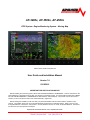
AF-3400s, AF-3500s, AF-4500s
EFIS System - Engine Monitoring System – Moving Map
Patents 6,271,769 B1 and 6,940,425
User Guide and Installation Manual
Version 7.4
03/12/2012
IMPORTANT PRE-INSTALLATION NOTICE
Before installing the monitoring system, READ THE LIMITED WARRANTY / AGREEMENT. There is information in the
Limited Warranty / Agreement that may alter your decision to install this product. IF YOU DO NOT ACCEPT THE TERMS
OF THE LIMITED WARRANTY / AGREEMENT DO NOT INSTALL THE PRODUCT. The product may be returned for a
refund if you do not accept the terms of the Limited Warranty / Agreement.
Before starting the installation, make sure that your planned installation will not interfere with the operation of any
controls. The installer should use current aircraft standards and practices to install this product. Refer to AC 43.13-2A,
Acceptable Methods, Techniques, and Practices - Aircraft Alterations and AC 43.13-1B, Acceptable Methods, Techniques,
and Practices--Aircraft Inspection and Repair.
Experimental instrument limited to use in experimental aircraft.
Advanced Flight Systems Inc. www.Advanced-Flight-Systems.com
PHONE: (503) 263-0037 FAX: (503) 263-1138
Not approved for use in aircraft with FAA type certificates.
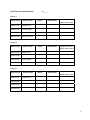
AF-3400s, AF-3500s, AF-4500s Post Installation Check
CAUTION: Do not fly the aircraft until the following check list has been completed.
Never Power the system with an automotive battery charger and the aircraft battery disconnected.
Before Power is Applied for the First Time
□ Screen mounted following the installation manual
□ Magnetometer mounted (Label up, connector forward)
□ Screen case has been properly grounded using center case screw
□ Wiring harness is properly connected to screen
□ Verify relay protection diodes are installed on all large aircraft relays (Master, Starter,
Avionics...etc)
□ Pitot/Static and AOA plumbing is secured to the correct ports on the screen
□ Trim Servo indication wires are connected per the installation manual wiring diagram
Applying Power for the First Time
□ Turn on aircraft battery power and power on the screens on.
□ Verify the unit powers up; read the warning message where the I AGREE button
is displayed. This page contains the software version installed along with any
mapping effective/expiration dates.
□ Set your clock time-zone offset
□ Set the AHRS Pitch Adjust for your aircraft's panel tilt (0 or 8 degrees typically)
□ Following the installation manual, calibrate the Fuel Tanks
□ Following the installation manual, calibrate all trim and flap position sensors
□ Set the airspeed V speeds based on your aircraft manufacturers
recommendations.
□ Set all engine temperatures/limits based on your engine manufacturers
recommendations
□ Set fuel tank, fuel pressure, fuel pressure, oil temperature, and oil pressure warning
parameters
□ Configure your Serial Ports based on devices connected
□ Configure your GPS/NAV Settings based on Serial Port selection
□ Verify all GPS and NAV sources are properly communicating with the EFIS. See
Appendix J: 430W - EFIS - Autpilot - ARINC Troubleshooting guide if you have an
autopilot and/or a Garmin GNS-430W/530W.
□ AOA Post-Installation Pre-Flight Checklist Completed
2
First Engine Start
□ With relay protection diodes installed, your AFS screen(s) can be turned on before the engine is
started.
□ After the engine has started, verify oil pressure and temperature. If none is indicated
SHUT DOWN the engine. Verify all wiring and consult your local A&P, the engine
manufacturer, and/or AFS technical support.
□ Verify all engine indications are correct per your engine manufacturers manual
Before First Flight
□ Verify you have the latest system software and mapping data (if applicable) - Visit the
AFS Website for latest software and map data.
□ Weight & Balance page updated with your aircrafts data
□ Checklist pages updated with information from your aircraft manufacturer
□ Magnetometer Alignment completed on all screens with an AHRS installed (See video on AFS
website Support Forum)
□ EFIS AOA Calibration Checklist completed
□ Pitot/Static check completed from an authorized FAA Repair Station.
□ EFIS and autopilot gains are set per the installation manual
In-Flight Configuration
□ Verify airspeed and altitude indicate correctly
□ Verify heading indicates correctly using a backup whiskey compass for reference
□ Test navigation sources and verify they function properly
□ If an autopilot is installed and coupled to the EFIS, check its functions
After First Flight
□ Calibrate Fuel Flow K-Factor (See Installation Manual)
AOA FLIGHT WARNING:
The EFIS may be shipped with AOA aircraft calibration data pre-installed. If you choose to use this data,
you must verify the validity of the data or calibrate the AOA to meet your specifications before using. You
must also read and understand the separate AOA manual before using the AOA instrument in flight.
2
3
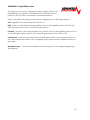
LIMITED WARRANTY / AGREEMENT
Advanced Flight Systems Inc. (“AFS”) warrants its aircraft monitoring system instrument and system components to be free from
defects in materials and workmanship for a period of one year commencing on the date of the first flight of the instrument or one
year after the invoice date, whichever comes first. AFS will repair or replace any instrument or system components under the terms
of this Warranty provided the item is returned to AFS prepaid.
This Warranty shall not apply to any unit or component that has been repaired or altered by any person other than AFS, or that has
been subjected to misuse, abuse, accident, incorrect wiring, or improper or unprofessional installation by any person. THIS
WARRANTY DOES NOT COVER ANY REIMBURSEMENT FOR ANYONE'S TIME FOR INSTALLATION, REMOVAL, ASSEMBLY
OR REPAIR. AFS reserves the right to determine the reason or cause for warranty repair.
1.
This Warranty does not extend to any engine, machine, aircraft, boat, vehicle or any other device to which the AFS monitoring
system may be connected, attached, or used with in any way.
2.
THE REMEDIES AVAILABLE TO THE PURCHASER ARE LIMITED TO REPAIR, REPLACEMENT, OR REFUND OF THE
PURCHASE PRICE OF THE PRODUCT, AT THE SOLE DISCRETION OF AFS. CONSEQUENTIAL DAMAGES, SUCH AS
DAMAGE TO THE ENGINE OR AIRCRAFT, ARE NOT COVERED, AND ARE EXCLUDED. DAMAGES FOR PHYSICAL
INJURY TO PERSON OR PROPERTY ARE NOT COVERED, AND ARE EXCLUDED.
3.
AFS is not liable for expenses incurred by the customer or installer due to AFS updates, modifications, improvements,
upgrades, changes, notices or alterations to the product.
4.
The pilot must understand the operation of this product before flying the aircraft. Do not allow anyone to operate the
aircraft that does not understand the operation of the monitoring system. Keep the operating manual in the aircraft at all
times.
5.
AFS is not responsible for shipping charges or damages incurred during shipment.
6.
No one is authorized to assume any other or additional liability for AFS in connection with the sale of AFS products.
7.
IF YOU DO NOT AGREE TO ACCEPT THE TERMS OF THIS WARRANTY, YOU MAY RETURN THE PRODUCT
FOR A FULL REFUND. IF YOU DO NOT AGREE TO ACCEPT THE TERMS OF THIS WARRANTY, DO NOT
INSTALL THE PRODUCT.
8.
This warranty is made only to the original purchaser and is not transferable. THIS WARRANTY IS IN LIEU OF ALL
OTHER WARRANTIES OR OBLIGATIONS, EXPRESS OR IMPLIED, ORAL OR WRITTEN. AFS EXPRESSLY
DISCLAIMS ALL IMPLIED WARRANTIES OF MERCHANTABILITY OR FITNESS FOR A PARTICULAR PURPOSE.
THE PURCHASER AGREES THAT IN NO EVENT SHALL AFS BE LIABLE FOR SPECIAL, INCIDENTAL OR
CONSEQUENTIAL DAMAGES, INCLUDING DAMAGES TO THE ENGINE OR AIRCRAFT, LOST PROFITS, LOSS OF
USE, OR OTHER ECONOMIC LOSS. EXCEPT AS EXPRESSLY PROVIDED HEREIN, AFS DISCLAIMS ALL OTHER
LIABILITY TO THE PURCHASER OR ANY OTHER PERSON IN CONNECTION WITH THE USE OR
PERFORMANCE OF AFS' PRODUCTS, INCLUDING BUT NOT LIMITED TO STRICT PRODUCTS LIABILITY IN
TORT.
4
THIS PAGE INTENTIONALLY LEFT BLANK
5
TableofContents
AF‐3400s, AF‐3500s, AF‐4500s Post Installation Check ___________________________________ 2 LIMITED WARRANTY / AGREEMENT __________________________________________________ 4 INTRODUCTION ________________________________________________________________________ 10 SYSTEM OPERATION ______________________________________________________________ 11 Power On / Off ________________________________________________________________________ 11 Battery Operation ______________________________________________________________________ 11 Screen Selection _______________________________________________________________________ 12 Enable/Disable Pages__________________________________________________________________________ 13 Knob List Configuration __________________________________________________________________ 13 EFIS Flight Display ______________________________________________________________________ 14 AHRS Alignment (Gyro) ________________________________________________________________________ 14 Dual AHRS Monitoring _________________________________________________________________________ 14 Screen Dimming ______________________________________________________________________________ 15 Barometric Pressure/Altitude ___________________________________________________________________ 15 Airspeed ____________________________________________________________________________________ 15 Horizon Roll and Pitch _________________________________________________________________________ 15 Altitude ____________________________________________________________________________________ 15 Heading – EFIS DG ____________________________________________________________________________ 16 Skid/Slip Ball (Inclinometer) ____________________________________________________________________ 16 Standard Rate Turn Indicator ___________________________________________________________________ 16 Vertical Speed _______________________________________________________________________________ 16 G‐Meter ____________________________________________________________________________________ 16 Flight Path Marker ____________________________________________________________________________ 17 EFIS Bugs (Airspeed, Altitude, Minimum Alt, Heading) ________________________________________________ 17 Clock/Timer Operation ________________________________________________________________________ 18 Angle of Attack (AOA) _________________________________________________________________________ 20 EFIS AOA CALIBRATION CHECK LIST ______________________________________________________________ 22 Synthetic Vision ________________________________________________________________________ 24 Terrain Awareness and Warning System (TAWS) ____________________________________________________ 24 Highway in the Sky (HITS) ______________________________________________________________________ 26 EFIS Navigation (HSI) ____________________________________________________________________ 28 GPS Navigation Display ________________________________________________________________________ 29 VOR Navigation Display ________________________________________________________________________ 31 Internal Flight Planning ________________________________________________________________________ 34 Autopilot Control / Flight Director _________________________________________________________ 36 Autopilot / Flight Director Control Settings ________________________________________________________ 39 The ABOUT Page _______________________________________________________________________ 43 Moving Map Display ____________________________________________________________________ 44 Map Features ________________________________________________________________________________ 44 Map Data Source _____________________________________________________________________________ 45 Private Airports ______________________________________________________________________________ 45 Intersections ________________________________________________________________________________ 45 Zoom Range _________________________________________________________________________________ 45 Nearest Airport ______________________________________________________________________________ 45 Direct To Navigation __________________________________________________________________________ 45 Airport Info _________________________________________________________________________________ 46 6
Airspace ____________________________________________________________________________________ 46 Track Mode _________________________________________________________________________________ 46 Map Database Files ___________________________________________________________________________ 47 Traffic Display _________________________________________________________________________ 49 Zaon XRX ___________________________________________________________________________________ 50 Garmin GTX‐330 _____________________________________________________________________________ 50 ADS‐B Traffic ________________________________________________________________________________ 50 To prevent seeing yourself called out as traffic (ghosting), connect one of the Serial outputs of the GTX‐330 configured as REMOTE + TIS to Pin 33 of the ADS600‐B box. Send the following command to the ADS600‐B. TXCP GTX330 _____________________________________________________________________________________ 50 Garmin GTS‐8xx TCAS System ___________________________________________________________________ 51 Weather Display _______________________________________________________________________ 52 XM Weather _________________________________________________________________________________ 53 ADS‐B Weather ______________________________________________________________________________ 55 IFR Approach Plates ____________________________________________________________________ 57 Engine Monitor Display __________________________________________________________________ 59 Fuel Computer _______________________________________________________________________________ 59 Fuel Flow Calibration __________________________________________________________________________ 60 % Power Display _____________________________________________________________________________ 61 EGT/CHT Display Modes _______________________________________________________________________ 63 Flight Times _________________________________________________________________________________ 63 Maintenance Log _____________________________________________________________________________ 65 Weight & Balance Screen ______________________________________________________________________ 66 Flight Data Logs ________________________________________________________________________ 67 Importing Flight Data to Excel ___________________________________________________________________ 67 AF‐3400/AF‐3500/AF‐4500 Installation _______________________________________________ 68 Mechanical Mounting ___________________________________________________________________ 68 Electrical Connections ___________________________________________________________________ 69 Audio Connections _____________________________________________________________________ 69 Volume Adjustment ___________________________________________________________________________ 69 EFIS Serial Data Connections _____________________________________________________________ 70 Serial Port # Function Hardware Setup ____________________________________________________________ 70 GPS/NAV # Data Source Software Setup ___________________________________________________________ 70 EFIS Serial Port Configuration Examples ____________________________________________________ 72 External Device Configuration ____________________________________________________________ 74 AF‐ARINC 429 ADAPTOR _______________________________________________________________________ 74 CO Guardian Display __________________________________________________________________________ 74 Garmin 430W/530W __________________________________________________________________________ 74 ARINC Module Software Updating _______________________________________________________________ 76 Garmin SL‐30 ________________________________________________________________________________ 77 Garmin 396/496 ______________________________________________________________________________ 77 Garmin GTX 327 / GTX 330 Transponder __________________________________________________________ 77 Chelton or OP EFIS ____________________________________________________________________________ 77 Magnetometer Installation _______________________________________________________________ 78 Magnetometer Alignment ______________________________________________________________________ 79 Outside Air Temperature Transducer Installation _____________________________________________ 79 Alarm Output __________________________________________________________________________ 79 EGT/CHT Installation ____________________________________________________________________ 80 7
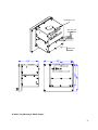
Propeller RPM Sensor Installation _________________________________________________________ 81 Oil Temperature Sensor Installation _______________________________________________________ 81 Amp Transducer Installation _____________________________________________________________ 82 Pressure Transducer Installation __________________________________________________________ 83 Oil Pressure Transducer Installation _______________________________________________________ 83 Fuel Pressure Transducer Installation ______________________________________________________ 83 Fuel Flow Transducer Installation _________________________________________________________ 84 Manifold Pressure Transducer Installation __________________________________________________ 85 Fuel Tank Level Sensor __________________________________________________________________ 86 Float Type __________________________________________________________________________________ 86 Capacitance Type _____________________________________________________________________________ 86 Trim & Flap Position Installation __________________________________________________________ 86 Instrument Calibration ____________________________________________________________ 87 Airspeed Color Range Settings ____________________________________________________________ 88 Altimeter Check ________________________________________________________________________ 88 RPM Calibration _______________________________________________________________________ 89 Fuel Tank Calibration ___________________________________________________________________ 89 Trim/Flap Calibration ___________________________________________________________________ 90 Test Audio ____________________________________________________________________________ 91 Switch Inputs __________________________________________________________________________ 91 Administrative Settings____________________________________________________________ 92 System Files _________________________________________________________________________________ 92 Multiple Screen Setup _________________________________________________________________________ 93 Dual AHRS Configuration _______________________________________________________________________ 93 APPENDIX A: Specifications ________________________________________________________ 95 Physical ____________________________________________________________________________________ 95 Power Requirements __________________________________________________________________________ 95 SD Card _____________________________________________________________________________________ 95 Clock Battery ________________________________________________________________________________ 95 Backup Battery _______________________________________________________________________________ 95 APPENDIX B: Hardware Specificiations _______________________________________________ 97 AF‐4500s Tray Mounting & ARINC Adapter __________________________________________________ 99 APPENDIX C: Electrical Connections _________________________________________________ 100 APPENDIX D: Metric Units ________________________________________________________ 103 APPENDIX E: Software Updates ____________________________________________________ 104 APPENDIX F: EFIS Activation Keys __________________________________________________ 105 APPENDIX G: Aerosance FADEC Interface ____________________________________________ 106 APPENDIX H: Eagle EMS Interface __________________________________________________ 107 APPENDIX I: AOA Pressure Port Location _____________________________________________ 108 8
APPENDIX J: Troubleshooting _____________________________________________________ 109 GNS‐430W/530W ‐ EFIS ‐ Autopilot ‐ ARINC Interface Troubleshooting _________________________ 110 APPENDIX K: Vertical Power VP‐X/PRO Interface _____________________________________ 116 APPENDIX L: Flight Director/AF‐Pilot Procedures flying an Approach ______________________ 117 Flying an LPV Approach _______________________________________________________________________ 117 Flying an ILS Approach ________________________________________________________________________ 121 APPENDIX M: SCHEMATICS ________________________________________________________ 122 Registration Information _________________________________________________________ 127 MANUAL REVISION HISTORY
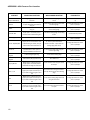
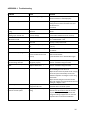
REVISION 6.7 7.0 DATE 2010 07/13/10 7.1 10/19/10 7.2 01/05/2011 7.3 09/01/2011 DESCRIPTION Updated Calibration Menu access Updated for new "s" CPU with Synthetic Vision updated autopilot control Updated post‐installation checklist Updated Weather & Traffic features Updated Trim & Flap indication calibration procedure Updated autopilot gain settings Updated ADS‐B traffic functions Added several screenshots Added wiring to prevent ghost traffic Updated ADS‐B wiring Added Appendix H: EagleEMS Added GTS‐8xx TCAS System to Traffic Display section Added HITS and Internal Flight Plan sections 9
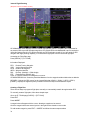
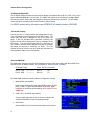
INTRODUCTION
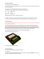
Advanced Flight Systems Inc. manufactures three different size EFIS and Engine Monitor systems. The AF-3400 uses a
6.5” display and the AF-3500 and AF-4500 use an 8.4” display. The new “s” CPU systems utilize our new high speed
CPU and support Synthetic Vision. The systems can be purchased as an EFIS only “EF”, Engine Monitor only “EM”, Multi
Function Display “MFD”, or as a single screen with both EFIS and Engine Monitor boards installed “EE”. Multiple systems
can be easily connected to share all data between screens. Install an EFIS “EF” and an Engine Monitor “EM” screen and
you will have the ability to display flight and engine instruments on both screens. Our EFIS Systems utilize
a Crossbow AHRS which is an AFS customized version of the certified Crossbow AHRS500.
WARNING
It is possible for any instrument to fail and display inaccurate readings. Therefore, you must be able to recognize an
instrument failure and you must be proficient in operating your aircraft safely in spite of an instrument failure. If you do not
have this knowledge, contact the FAA or a local flight instructor for training. The ability for this product to detect a problem is directly
related to the pilot’s ability to program proper limits and the pilot’s interpretation and observation skills. The pilot must understand the
operation of this product before flying the aircraft. Do not allow anyone to operate the aircraft that does not know the operation of this
product. A copy of this manual must be kept in the aircraft at all times.
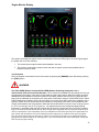
The AF-3400/3500/4500 will automatically turn on any time power is applied to the unit.
NOTE: The system is designed to remove a gauge needle from the screen if a transducer is disconnected.
Each gauge can have an upper and lower caution and warning limit. If a gauge is in the caution area the needle and value
will turn yellow. If a gauge is in the warning area the needle and value will turn red.
If the engine RPM is greater than 500rpm and a gauge is in the warning area the gauge name will be displayed over button
1 in red and an audible warning will generated. For example if the oil pressure is low you should hear “Check Oil
Pressure”, this will repeat every 5 seconds until the gauge is no longer in the warning area or you press button 1 to
acknowledge the error and stop the audible warning for that gauge.
The system will give the audible warning “Check Fuel Computer” on startup if the fuel computer’s gallons remaining value
does not match the fuel tanks level. This feature (if turned on in Instrument Calibration) should warn you if you have added
fuel and forget to adjust the fuel computer. The number of gallons that will generate an error is adjusted in Instrument
Calibrate. Since the fuel levels are NOT accurate when the tanks are near full this value is doubled when the tanks show
full.
See Instrument Calibration for directions on setting the upper and lower caution and warning limits.
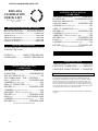
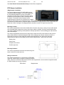
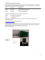
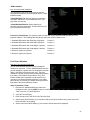
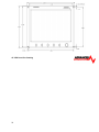
SD Card Slot
SD Card ICON
[Left Knob/Button]
(AF-4500 Only)
10
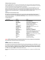
[Button1] [Button2] [Button3] [Button4] [Button5] [Right Knob/Button]
(Joystick AF-4500 Only
Knobs and Buttons
The AF-3400 and 3500 have 5 buttons and one rotary knob with a push button for data input.
The AF-4500 has a left rotary knob, 5 buttons and one rotary/joy stick knob on the right side with a push
button for data input.
SYSTEM OPERATION
Power On / Off
For wiring information see APPENDIX K
Turning the Unit ON
The AF-3400/3500/4500 will turn on anytime power is applied to the Master or Backup power input and will
stay running as long as there is power supplied to one of the inputs. If you have the optional internal battery
the system can be turned on by pressing and holding [Button 1] for 2 seconds.
Turning the Unit OFF
The AF-3400/3500/4500 will turn off when power is removed from the Master and Backup power inputs. If
power is turned off and you have the optional battery installed you will get the following message:
If you press any of the buttons the EFIS will stay on using battery power.
Battery Shutdown
The AF-3400/3500/4500 can be turned off when on battery power by pressing and holding [Button 2],
[Button 3], or [Button 4] for three seconds. The unit will also turn off when on battery power if you do not
have airspeed or RPM for 5 minutes or if the battery drained.
Battery Operation
The optional internal battery is designed to allow the unit to operate in the event of an external power failure.
• The internal battery is a lithium ion battery and is recharged whenever input power is connected.
• When new, a fully charged battery is rated for 1 hour of normal operation. The screen will
automatically dim when running on battery power to help conserve battery life.
If you lose external power in flight and the system is running on the internal battery you should land at the next
available airport. There are many factors that can reduce battery life.
DO NOT ASSUME THAT YOU HAVE ONE HOUR OF BATTERY LIFE.
NEVER TAKE OFF USING BACKUP BATTERY POWER.
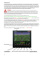
When the unit is running on internal battery power a battery status ICON is displayed on the lower right hand
corner of the display.
Low Battery
Full Battery
11
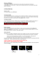
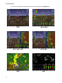
Screen Selection
You can rotate through the enabled screens on the unit by pressing the [PAGE] button.
12
EFIS
EFIS & EMS
EFIS - EMS - MAP
EFIS & MAP
MAP
EMS
Six-Pack Panel Page ("s" CPU)
AIR and EMS (non “s” CPU only)
Enable/Disable Pages
You can select what pages are in the screen rotation from the [EFIS] -> [Settings] -> [More] menu by
pressing the <Page List> knob button. The knob is used to enable or disable each item. After selecting the
desired pages be sure and press the [SAVE] button. Some pages on the list may be grayed out if you didn't
purchase those features or disabled them in the Calibration Menu (MAP & VPX).
Knob List Configuration
You can select which items appear on the knob pop up list when you press the
knob button from the [EFIS] -> [Settings] -> [More] -> [Page List] -> [Knob
List] menu. The knob is used to enable or disable each item. After selecting the
desired items be sure and press the [SAVE] button. Some items will appear on
the list on certain pages even when turned off; DIM is always available on the
checklist page, ZOOM is always available on a map page.
The knob pop-up menu selection can be configured for PUSH SEL (press the
knob to select next item in list) or TURN SEL (turn the knob to select item in
list) from the KNOBLIST menu.
13
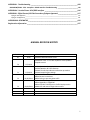
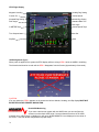
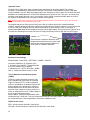
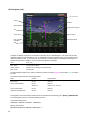
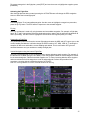
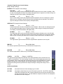
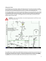
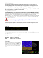
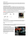
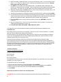
EFIS Flight Display
Magnetic Heading
Heading Bug Setting
Current G’s
Vertical Speed
Airspeed Bug Setting
Altitude Bug Setting
Pitch Angle
Standard Rate Turn
Roll Angle
G METER Tape
Vertical Speed Tape
True Airspeed
Baro Set
Slip Ball
Wind
AHRS Alignment (Gyro)
When power is applied to the system the EFIS display will have a large RED X while the AHRS in initializing.
The Aircraft should not be moved until the RED X disappears from the Screen (Approximately 40 seconds).
CAUTION:
If for any reason the RED X appears on the screen the Horizon Attitude, Heading, and Slip display MUST NOT
BE RELIED ON FOR PRIMARY NAVIGATION.
Dual AHRS Monitoring
If you have a dual screen system with two AHRS units you can configure the
screens to monitor both AHRS units. If a screen detects that there is an AHRS
mismatch error in Roll, Pitch, or Heading you will get an AHRS MISMATCH error displayed on the center of
the screen. See Dual AHRS configuration for proper setup.
14
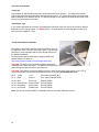
Screen Dimming
The screen can be dimmed from the Checklist page by turning the right knob anytime the
word DIM is displayed. If DIM is not displayed press the knob and select DIM from the list.
Barometric Pressure/Altitude
The current barometer setting is displayed in the box below the altitude tape. The
value is shown in either inches of Mercury or millibars. The current barometer setting
can be adjusted by turning the knob anytime the word BARO is displayed. If BARO
is not displayed press the knob until it is displayed. The current field elevation is
stored in memory so that the altitude should be correct on power on.
Airspeed
The airspeed is displayed on the left side of the screen using an analog 4 colored tape and digital
readout. The airspeed range marks can be adjusted in Instrument Calibration under Airspeed. The
airspeed units are displayed in both the upper Indicated Airspeed box and the lower True Airspeed
box. A barber pole style hash will automatically show above Vne.
Horizon Roll and Pitch
The horizon (roll and pitch) works the same way that you would
expect a traditional artificial horizon to work. The white zero pitch line
stays parallel to the actual horizon regardless of the aircrafts pitch and
roll. If you have the new “s” CPU and have the SV enabled you will
notice that the zero pitch line is not always on the horizon. If the
display is showing terrain above the zero-pitch line, your aircraft is
below the upcoming terrain.
The parallel lines above and below the horizon line are the pitch
indicator lines. Similarly the arrow rotating around the roll indicator
gives you visual representation of your current roll angle. Each mark
represents 10 degrees of roll with longer marks at 0, 30, 45, and 60.
The pitch line can be adjusted for level flight from the main EFIS page
by pressing the following buttons [EFIS] -> [SETTINGS] -> [PITCH
ADJ] The right knob is then used to adjust for level flight pitch.
Altitude
The altitude tape gives you a visual representation of your altitude.
The digital readout points to your current altitude, thousands of feet
are displayed using large numbers while hundreds of feet are
displayed using smaller numbers. The green chevrons are located at
1000’ intervals for IFR cruising altitudes and the white chevrons are
located at 500’ indicating VFR cruising altitudes. Above the tape are
two boxes showing the value of the two altitude bugs. The main ALT
bug is for the Flight Director altitude pre-select. It's altitude is shown
in the upper box. The lower box displays altitude for the MIN ALT bug
which is used to program a DH/MDA for an IFR approach.
15
Heading – EFIS DG
This heading is displayed like a standard slaved directional gyro.
The digital readout in the pointer shows your current heading. If
the EFIS DG is red, the heading should not be relied on and you
should check the magnetometer wiring.
Skid/Slip Ball (Inclinometer)
The skid/slip ball works like any standard mechanical
gauge. If the ball is within the black lines, then you are in coordinated flight. The ball on the
outside of a turn indicates a skid, while the ball on the inside of a turn indicates a slip.
Standard Rate Turn Indicator
The required bank angle for a standard rate turn is indicated by a white triangle on
the roll scale. If you align the yellow bank angle pointer with one of the white triangles
you should complete a 180º turn in 1 minute. The required bank angle will change
with airspeed and the triangles will disappear below 30 kts.
Vertical Speed
The vertical speed is displayed using a green bar located on the right side of the altimeter tape. The bar
will increase upward for climbing flight and increase downward for descending flight. The digital vertical
speed will be displayed on the top of the gauge in a climb and on the bottom of the gauge for a descent.
G-Meter
The G-Meter is located next to the Airspeed tape. The current G loading will be displayed with a
green bar. The G-Meter options are selected from the following menu:
[EFIS] -> [G METER]
From the G Meter menu you can:
Turn the G Meter On/Off
Reset the G Meter.
The G Meter is limited to +/- 5 G’s and will record the maximum and minimum G’s that
the aircraft has seen since the last time the Reset button was pressed with a green
marker on the scale.
16
Flight Path Marker
The green flight path marker (FPM) or velocity vector shows where the aircraft is
actually moving. Think of it as a visual representation of GPS Track. The green
target will only be centered under steady state flight conditions with no wind.
Usually the target will be moving around the display showing where the airplane
is going, not where the nose is pointed. If you have a strong cross wind from the
left you will see the FPM move to the right. If you keep the FPM on the horizon
line you will maintain level flight, even during steep turns. The FPM requires a
valid GPS signal be present and Synthetic Vision enabled. The FPM will be red
if there is no GPS signal or there is not enough room on the screen to show the FPM deviation.
EFIS Bugs (Airspeed, Altitude, Minimum Alt, Heading)
Altitude Bug
The Altitude Bug can be turned on and off from the [EFIS] -> [NAVIGATION] -> [BUGS] -> [ALT]
menu. If the Altitude Bug is on and the text over the knob is <-ALT-> the knob will set the desired
altitude bug location. If the text is not <-ALT-> you should press the knob button until it appears.
Holding the knob down for two seconds will sync the altitude bug to the current altitude. The box on
the top of the altitude tape shows the current bug location and will have a black background when
selected.
Altitude Alerting
The Altitude Alerting function provides visual and voice “ALTITUDE” alerts when approaching the Altitude Bug.
Upon passing through 100 feet of the Selected Altitude, the Altitude Bug changes from White to Yellow
When the aircraft passes within 200 ft of the Selected Altitude, the Altitude Bug changes from Yellow to
Cyan, and the voice alert “ALTITUDE” is generated.
After reaching the Selected Altitude the pilot flies outside of the deviation band (±200 feet of the Altitude
Bug), the Altitude Bug changes from Cyan to Yellow, and the voice alert “ALTITUDE” is generated.
Altitude > 1000’ of Bug
1000’ > Altitude > 200’ of Bug
Altitude < 200’ of Bug
Minimum Descent Altitude/Decision Height Bug
A barometric Minimum Descent Altitude Bug (MDA, or Decision Height, DH) is displayed whenever the
altitude bug is turned on. If the MDA Bug is on and the text over the knob is <-MIN ALT-> the knob will set
the desired MDA bug location. If the text is not <-MIN ALT-> you should press the knob button until it appears.
Holding the knob down for two seconds will sync the bug to the current altitude. The second box on the top of the
altitude tape shows the current bug location and will have a black background when selected.
MDA/DH Alerting
The MDA Alerting function provides visual and voice “MINIMUMS” alerts when approaching the Bug.
17
Upon passing through 100 feet of the Selected Altitude, the Bug changes from Cyan to White.
After reaching the Selected Altitude the Bug changes from White to Yellow, and the voice alert
“MINIMUMS” is generated.
Altitude > 100’ of MDA Bug
100’ > Altitude > MDA Bug
Altitude < MDA Bug “MIMIMUMS”
Airspeed Bug
The Airspeed Bug can be turned on and off from the [EFIS] -> [NAVIGATION] ->
[BUGS] -> [SPD] menu. If the Airspeed Bug is on and the text over the knob is <-SPD->
the knob will set the desired airspeed bug location. If the text is not <-SPD-> you should
press the knob button until it appears. Holding the knob down for two seconds will sync
the airspeed bug to the current airspeed. The box on the top of the airspeed tape shows
the current bug location and will have a black background when selected
Heading Bug
The Heading Bug can be turned on and off from the [EFIS] -> [NAVIGATION] ->
[BUGS] -> [HDG] menu. If the Heading Bug is on and the text over the knob is <HDG-> the knob will set the desired heading bug location. If the text is not <-HDG> you should press the knob button until it appears. Holding the knob down for two
seconds will sync the heading bug to the current magnetic heading. The text next
to the heading box shows the current bug location and will have a black
background when selected.
The knob and joystick on the AF-4500 can be used as a shortcut for HDG & CRS, ALT
& VS. If the ALT bug is changed and then the joystick is pressed in, the VS function
will automatically become active. If the VS is not changed, the joystick function will
return to normal after 2 seconds. This feature also applies to the left knob. When HDG
is changed, the knob can be pressed within 2 seconds to automatically change the
function to CRS. After 2 seconds of no activity, normal knob functionality will be
restored.
Clock/Timer Operation
The time functions can be accessed from the main screen by pressing the [TIMER] button.
Clock Setting
Press the [CLOCK] then [SET] buttons to enter the date/time adjustment menu. The knob is used to
adjust each field and the knob is pressed to advance to the next field. First set the time in Zulu format,
then the date, and finally the last field is your local time offset.
18
Timer Functions
The system has a count-down and count-up timer that is accessed by pressing the [TIMER] button in the
main menu. The timer value is adjusted with the knob and controlled using the buttons:
[START] [STOP]
[RESET]
[UP/DWN] [ADJ]
The Up or Down mode is displayed with an arrow on the screen. If Count Down mode is selected, the
right knob is used to set the starting time. The timer display will flash green when 0:00 is reached and you
will get the voice alert “TIMER”. The RESET button acts differently based on Timer mode. In Count Down
mode, the RESET button will reset the time to the last programmed time. In Count Up mode, the RESET
button will change the timer to 0:00.
Once the timer is activated it is displayed on the upper left corner of the screen replacing the clock. The
clock can be returned by pressing [TIMER] then [CLOCK] buttons.
Dual Screen Clock Setting
The current time on the other screen can be set by pressing the [NET SYNC] button from the time menu
on the current display. When you press the [NET SYNC] button the time is sent over the Ethernet
connection to the other screen and its clock is set to match the current screen.
19
Angle of Attack (AOA)
See Appendix I: AOA Pressure Port Location
The EFIS can display an AOA if you have installed the optional AOA system. You will need to
perform an in flight AOA calibration if your unit has not been loaded with precalibrated AOA
data.
The AOA in flight settings can be adjusted from following Menu:
[EFIS] -> [SETTINGS] -> [AOA]
Button 2 in the AOA menu controls the AOA display.
OFF
The AOA display is always off
ON
The AOA display is always on
DECLUTTER The AOA display will be on if the angle of attack is greater than the AOA declutter
segment in the EFIS AOA calibration menu. We have found the ideal setting for declutter is 8.
The segments are numbered using the following:
23
16
12
6
Warning - RED Only
Approach - Yellow lined up with the center of the donut
L/D Max - Split Green bar
Bottom Green Bar.
Flap Sensor
The AOA indicator can use either the flap position sensor for the screen or the supplied switch connected
to Input #3 on the main EFIS harness. The AOA "Use Flap Angle Sensor" should be set to YES if you
have installed the Linear Flap Position Sensor for the screen in Instrument Calibration.
4. AOA
13. Use Flap Angle Sensor
16. Declutter Segment
YES/NO
8
AOA Display
The center round donut will be green when the flaps are down and black when they are up. For a
detailed explanation of the AOA system please refer to the separate AOA manual and the EFIS AOA
Calibration Checklist. The numbers below the display are degrees angle of attack in tenths. If the AOA is
properly calibrated you should get the following displays. As your angle of attack increases the display will
lose bars.
L/D Max
20
This is the best
engine out glide
AOA.
This is the desired
AOA for a normal
approach.
Approach
Warning
This should indicate
that you are 15%
above stall and you
will get the verbal
“Angle Angle Push”.
This should indicate
just as you reach
the stalling AOA
STALL
THIS PAGE INTENTIONALLY LEFT BLANK
21
EFIS AOA CALIBRATION CHECK LIST
EFIS AOA
CALIBRATION
CHECK LIST
EFIS_cklst.doc
09/2010
paper color Green
rev 3
POST INSTALLATION PRE FLIGHT
Blow into Blue tube at CPU -------- Air exits Upper Wing Port
Blow into Green tube at CPU ------- Air exits lower Wing Port
PITOT/STATIC LEAK TEST ------------------- COMPLETED
AIRCRAFT LOG ---------------------------------------UPDATED
AIRCRAFT CHECKLISTS ---------------------------UPDATED
ANNUAL CONDITION C/L -------------------------UPDATED
CHAPTER IX TESTING ------------------------- COMPLETED
HANGAR CALIBRATION
The only thing that is required for the EFIS AOA is
to check the flap switch.
LANDING CONFIGURATION
CALIBRATION
AIRCRAFT LOCATION..................... AIRBORNE
FLAPS/GEAR.................... CONFIRMED DOWN
EFIS AOA DISPLAY ON ................................. ON
AOA CAL Button ....................... PUSH/RELEASE
CONFIRM flap down calibrate page ............................. 1OL
ZERO “G” MANEUVER for 1/2 sec. ................... YES
RECORD button ............................. PUSH/RELEASE
CONFIRM flap down angle advisory page...................... 1AA
AIRSPEED 1.15Vso descending slow flight ............... YES
RECORD button ............................. PUSH/RELEASE
PAGE button ............................ 2x PUSH/RELEASE
CONFIRM save data to non-volatile memory page .............. 1SA
RECORD button ............................. PUSH/RELEASE
YOU ARE NOW IN THE FLIGHT MODE
FLAPS UP ..................... DONUT CHECKED OFF
FLAPS DOWN ............... DONUT CHECKED ON
CRUISE CONFIGURATION
CALIBRATION
AIRCRAFT LOCATION..................... AIRBORNE
FLAPS/GEAR........................... CONFIRMED UP
EFIS AOA DISPLAY ON ................................. ON
AOA Calibrate Menu EFIS -> SETTINGS ->
AOA -> AOA CAL ..................... PUSH/RELEASE
CONFIRM flap up calibrate page ................................ 0OL
ZERO “G” MANEUVER for 1/2 sec. ................... YES
RECORD button ............................ PUSH/RELEASE
CONFIRM flap up angle advisory page ......................... 0AA
AIRSPEED 1.15Vs1 descending slow flight ............... YES
RECORD button ............................ PUSH/RELEASE
PAGE button ............................ 2x PUSH/RELEASE
CONFIRM save data to non-volatile memory page .............. 0SA
RECORD button ............................. PUSH/RELEASE
YOU ARE NOW IN THE FLIGHT MODE
22
FLIGHT TEST AOA
VERIFICATION C/L ------------------- COMPLETE
CHAPTER X CALIBRATING ------- COMPLETE
CHAPTER X FLIGHT TESTING --- COMPLETE
FLY THE AIRPLANE & WATCH FOR TRAFFIC!
The POST INSTALLATION and HANGAR CALIBRATION CHECK
LISTS must be completed prior to flight. The zero “G” maneuver requires
that all unsecured items be removed from the aircraft prior to flight. Two
pilots are required during the calibration process and one will be assigned
the task to fly the aircraft and nothing more. The flight calibration area will
be cleared for traffic and will be at a safe altitude with the IAS always within
the green IAS band. Stalls are not required or desired!
Push button in for 1/2 second and then releasing the button is proper button
technique.
THIS PAGE INTENTIONALLY LEFT BLANK
23
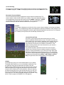
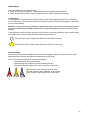
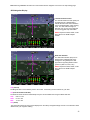
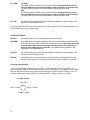
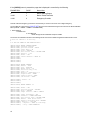
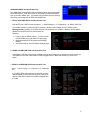
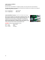
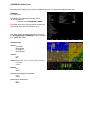
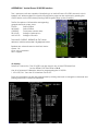
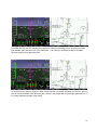
Synthetic Vision
Synthetic Vision (SVN) gives users a forward looking perspective of the terrain ahead. This includes
mountains, rivers/waterways, obstacles and runways. The Synthetic Vision database requires a Map Data
card be installed in the unit. While the mapping option isn't necessary for SVN to work, the two share the same
databases on the Map Data card. Grid lines are displayed on the ground of SVN. They are 1 arc minute lines,
meaning at the equator they are 1nm by 1nm squares. As the aircraft is positioned farther North or South of
the equator, the East/West lines of the grid are drawn closer together.
Note: Having synthetic vision changes the way the attitude indicator behaves; users will want to spend time flying with
SVN in visual conditions before attempting to fly in IMC.
The biggest change new SVN users will notice is the lack of a definite horizon like a standard attitude
indicator. Attitude indicators traditionally represent level flight when the miniature airplane is on the intersection
of the blue and brown shading. Since in real life the aircraft is not level with the horizon in level flight, a
synthetic zero pitch line has to be displayed over the primary flight display. This zero pitch line is shown as at
thin white line extending from the left side of the PFD page all the way to the far right side of the PFD page.
Zero Pitch Line
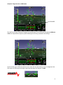
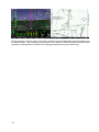
SVN will show a maximum distance of 3nm
ahead of the aircraft when on the ground and
achieves the maximum possible distance of
50nm when at 1,800AGL and above.
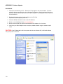
Synthetic Vision Settings
Enable/Disable - Press EFIS -> SETTINGS -> MORE -> ON/OFF
Instrument Calibration: 35: Synthetic Vision
1. Synthetic Vision ON/OFF - Enables/Disables
SVT (if the software key is installed)
2. Altitude Source - (AUTO, GPS ONLY, BARO
ONLY) - Selects the altitude source for SVN
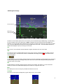
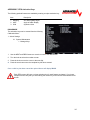
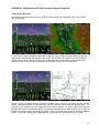
Terrain Awareness and Warning System
(TAWS)
TAWS is a system designed to keep the pilot
alert of altitudes that could result in Controlled
Flight into Terrain (CFIT). Terrain is shaded in
yellow or red based on the altitude of the aircraft
and the altitude of the terrain below. When the
distance between the aircraft and terrain below
becomes close enough to present a conflict, the
terrain is colored yellow or red. TAWS is drawn in
a 6nm square around the aircraft.
When enabled, TAWS arms automatically when
climbing through 1,200ft AGL. This is to prevent false warnings in the traffic pattern. TAWS is disabled when
the aircraft slows to the shutoff speed set in Instrument Calibration under
TAWS Terrain Colors:
RED - Aircraft is within 100ft AGL of the terrain
YELLOW - Aircraft is between 1,000ft AGL and 100ft AGL of the terrain.
24
TAWS Settings
Instrument Calibration: 35: Synthetic Vision
3. Terrain Warning (TAWS) ON/OFF - Enables/Disables terrain shading based on altitude
4. TAWS Airspeed Shutoff (KTS) - Sets the airspeed at which TAWS is disabled (for landing).
Traffic Display
If a traffic device is connected to your EFIS monitor, the traffic will be displayed on the SVN. Traffic shown
must be within 6nm of your aircraft and within the 60 degree view cone of the SVN 30 degrees on either side
of your current heading).
Example: The top down map may show traffic in 360 degree directions around you and could be 25nm ahead of
you. However traffic depicted on SVN is limited to 6nm in range and 30 degrees on either side of your aircrafts
heading.
Traffic depicted on SVN is similar to the map view, but with only 2 symbol possibilities. Since all traffic shown
will be within 6nm, we don't display the diamond with a square inside of it.
Proximity Traffic (within 1200ft relative altitude and less than 6nm range)
Traffic Advisory (within 1200ft relative altitude and less than 0.2nm range)
Obstacle Display
SVN shares the same obstacle database as the top-down map page. Obstacles are shown at their proper
height above ground and at their bases are drawn at half of their height.
There are several exclusions users will want to be aware of:
- Obstacles beyond 18nm are not shown
- Obstacles less than 1000ft AGL are not shown beyond 6nm
- Obstacles more than 2,000ft AGL below the aircraft are not shown
RED: Aircraft is within 100ft AGL of top of tower
YELLOW: Aircraft is within 600ft AGL of top of tower
GRAY: Aircraft is within 2000ft AGL of top of tower.
25
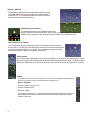
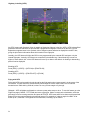
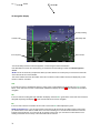
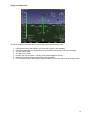
Highway in the Sky (HITS)
Any EFIS system with Synthetic Vision is capable of displaying Highway in the Sky (HITS). HITS is the artificial
generation of boxes that direct the pilot towards a programmed navigation course set by the GPS. HITS is
depicted as magenta boxes in the synthetic vision. Waypoint names will also be displayed in the HITS box,
giving the pilot further information about their location on the flight plan.
Laterally, the HITS boxes will follow the GPS course programmed by the external GPS navigator or by the
internal flight plan. Vertically, HITS boxes are controlled by the altitude bug. If the altitude bug is reset to a
higher or lower altitude, ALL of the HITS boxes will move up or down to the altitude. A climbing or descending
path will not be displayed.
Enabling HITS
Press [EFIS] -> [AP/FD] -> [HITS ON| or [FD/HITS ON]
Disabling HITS
Press [EFIS] -> [AP/FD] -> [FD/HITS OFF] or [FD ON]
Flying with HITS
Flying with HITS involves positioning the aircraft so the flight path marker (green target) is in the center of the
HITS boxes. This will ensure the aircraft actually flies through the center of the boxes. The HITS boxes
themselves are 700ft wide by 200ft tall, so there is a very narrow margin to fly through.
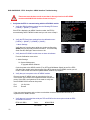
Glidepath - HITS will display a glidepath to a chosen runway when setup to do so. To use this feature go to the
Flight Plan page (CHECK -> FLT PLAN) and enter a flight plan. Select a runway at the destination, select the
glide-angle, enter a crossing restriction and press ACTIVATE. HITS boxes will then be drawn at the prescribed
angle up from the runway selected to the altitude entered. For example, a 3 degree angle from RWY 35 at
KUAO up to 1,500ft MSL. The highest box will flash white, indicating Top of Decent.
26
Currently HITS boxes are not drawn for a descent. If the ALT bug is moved to select a lower altitude, the HITS
boxes will descend to that altitude, however a vertical descending path will not be drawn. In the screenshot
above, the aircraft altitude is 8,000ft, however the ALT bug (and HITS boxes) are drawn at 7,000ft.
27
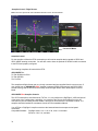
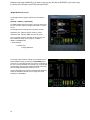
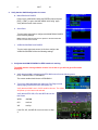
EFIS Navigation (HSI)
Course Needle
To/From
Identifier
Bearing Needle
Target Vertical Speeds
CDI
Course Source
Bearing Source
NAV Type
(VOR/GPS)
FD/Autopilot Mode
CRS
The EFIS can display an HSI when connected to a Nav radio, GPS, or GPS Navigator. The system has two main
navigation needles; Course and Bearing. You can individually select the navigation source for each needle from any
radio connected to the unit. If you have an SL-30 connected, you will also get a second bearing needle when the
standby Nav frequency is enabled. The source label will indicate the radio type:
Label
Radio Type
NAV1, NAV2
SL-30 Nav/Comm Radio
GNAV1, GNAV2
GPS/NAV/Comm Navigator (430W,530W,480)
GPS1, GPS2
GPS Receiver
The CDI Needle and data is color coded to indicate the source of the data; Magenta for GPS data, Green for VOR or
ILS data.
We currently support data from the following radios:
Radio
Interface
Supported Data
Garmin SL-30
RS-232
VOR, ILS
Garmin 430W/530W/480
RS-232
GPS CDI
ARINC 429
GPS CDI, LPV, VOR, ILS
Garmin x95/x96 Series
RS-232
GPS CDI
GPS Radio with NMEA-0183
RS-232
GPS CDI
The navigation course and bearing needle sources are selected from the following menu: [EFIS] -> [NAVIGATION]
From the navigation menu you can select following sources:
Course CDI needle source:
CRS/NONE, CRS/GPS1, CRS/NAV1, CRS/GNAV1,…..
Bearing needle source:
BRG/NONE, BRG/GPS1, BRG/NAV1, BRG/GNAV1,…..
28
Note: Selecting CRS/MAP will match the course needle with the navigation source set in the map settings page
GPS Navigation Display
Vertical Deviation Pointer
The Vertical Deviation Pointer (VDP) can
be displayed from a WAAS GPS to
indicate the baro-VNV vertical deviation
when Vertical Navigation (VNV) is being
used. The VDP should change to a
diamond once you are on the approach
and receiving glide slope information.
NOTE: Requires a 430W, 530W, or 480
along with the AF-ARINC adaptor
module.
Glide Path Indicator
The Glide Path Indicator (GPI) can be
displayed from a WAAS GPS and is
analogous to the glideslope for GPS
approaches supporting WAAS vertical
guidance (LNAV+V,L/VNV, LPV)
NOTE: Requires a 430W, 530W, or 480
along with the AF-ARINC adaptor
module.
CRS (Course)
The Magenta GPS course indicator points to the current course that you have selected on your GPS.
CDI (Course Deviation Indicator)
The GPS CDI scale should be automatically set by the remote WAAS radio using the ARINC data line:
APR:
TRM:
ENR:
0.06 nm / dot
0.2 nm / dot
1.0 nm / dot
TRK (Track)
The current GPS track over the ground is displayed on the HSI by a Magenta triangle. If there is a crosswind it will be
different than your magnetic heading.
29
BTW (Bearing to Active)
BTW displays the direct bearing to the active GPS waypoint and will be displayed on the HSI as a yellow line with two
arrows. If you are flying directly to the waypoint on the GPS Course the BTW needle will be under the Magenta
needle.
DTW (Distance to Waypoint)
DTW displays the nautical miles to the current GPS waypoint.
SPD (Speed)
SPD displays the current ground speed in nautical miles per hour.
WPID (Waypoint Identfier)
WPID displays the current waypoint ID from the GPS.
30
VOR Navigation Display
To/From Indicator
OBS Setting
VOR Frequency
The Green course indicator points to the current course you have selected using the OBS setting. The OBS setting
can be set using the knob on the EFIS when <-CRS-> is displayed over the knob (press the knob if CRS is not
displayed). The current OBS setting is displayed in the text area. If the Nav radio is tuned to a VOR, this is the radial
to fly. The SL-30 OBS setting can also be set using the OBS button on the radio. The radio identifier will also be
decoded and displayed only if you are using an SL-30 radio.
CDI
Each dot in the course deviation indicator indicates 2 degrees of deviation from the course radial.
VOR
If the radio is tuned to a standard VOR frequency and is giving a valid TO / FROM indication the display will show
VOR in green letters. If the radio does not have a valid indication the display will show VOR and it should not be
used for navigation.
BTA
The BTA (Bearing To Active) displays the direct bearing to the active VOR station and will be displayed on the HSI as
a yellow bearing needle. If you are flying directly to the VOR on the Course OBS setting the bearing needle will be
under the Green course needle.
BTS
The BTS (Bearing To Standby) displays the direct bearing to the Standby VOR station if you have selected M
(monitor) on the SL-30. The BTS will be displayed on the HSI as a orange line with a circle.
IDNT
IDNT displays the current nav frequency identifier decoded from the SL-30.
TO/FROM
The To/From radio flag will be displayed by a green triangle on the course needle.
31
TO
FROM
ILS Navigation Display
Runway Heading
Localizer CDI
Glide Slope VDI
ILS Frequency
AP/FD Mode
You should always set the ILS inbound Approach Course using the CRS knob selection.
If the Nav Radio is tuned to an ILS frequency you should use the CRS setting to select the inbound approach
course.
NOTE: The SL-30 will not let you adjust the OBS if you have selected an ILS freq and you must use the CRS knob
on the EFIS to set the course indicator.
The course indicator is fixed to the rotation of the DG. The Green course indicator will only be displayed if you are
tuned to a VOR or a localizer.
LOC
If the radio is tuned to a standard ILS frequency and is giving a valid indication the display will show LOC in green
letters. If the radio does not have a valid localizer indication the display will show LOC and it should not be used for
navigation.
GS
If the nav radio has a valid glide slope indication the display will show GS in green letters. If the radio does not have a
valid glide slope flag it will display GS in red and it should not be used for navigation.
BC
If the nav radio is tuned to a localizer and is in back course mode BC will be displayed in green.
NOTE on Back-Course: If you are flying a back-course with an HSI and the SL-30 is NOT in back-course mode,
you should set the course selector “OBS” to the front course heading so no reversal will be needed since the CDI
indicator spins with the DG. If you have the SL-30 in back-course mode, you must set the course selector to the
heading of the back-course runway or the CDI needle will be reversed.
32
33
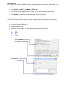
Internal Flight Planning
(Requires Version 8 software or later)
AF-3000s/4000s series displays have an internal flight planning feature, eliminating the requirement for
an external GPS to provide flight plan waypoints. Only a basic GPS with NMEA data output is required to
utilize this feature (though it can still be used with any GPS navigator as well). If you have another GPS
navigator with flight planning capability, it will transfer the flight plan to the EFIS internal flight plan.
Accessing the Flight Plan page
Press [CHECK] -> [FLT PLAN]
Information Displayed:
DTK: Desired Track to Waypoint
VSR: Vertical Speed Required
DTW: Distance to Waypoint
WPID: Waypoint Identifier
RW:
Runway: (Number) > (Glide Angle)
ETE: Estimated time Enroute (leg)
Cross xx Before: Distance from waypoint to cross at
AT/ABOVE/BELOW xxx: Cross the prescribed distance from the waypoint at/above/below the set altitude
[SRCSEL] - Selects the GPS source for the internal flight plan (GNAV 1 / GNAV 2 / GPS1 / GPS 2)
[CHART] - Displays the approach plate (if installed on the SD Card) for the destination airport
Creating a Flight Plan
There are two ways to program a flight plan; manually or automatically transfer through another GPS.
To manually create a flight plan, follow these simple steps:
Go to the FLT PLAN page [CHECK] -> [FLT PLAN]
Press EDIT
Press INSERT
A waypoint box will appear with the cursor, allowing a waypoint to be entered
Once the waypoint has been entered, press in the right knob to deselect cursor mode
To add another waypoint, press EDIT -> INSERT and follow the same steps as above
34
To remove a waypoint in the flight plan, press [EDIT] and use the cursor to highlight the waypoint, press
[REMOVE]
Activating the Flight Plan
After the flight plan has been created, pressing the ACTIVATE button will change the EFIS navigation
source to follow the internal flight plan.
Direct-To
Proceeding Direct-To an intermediate waypoint: Use the cursor to highlight the waypoint to proceed to,
press the [D-To] button. The EFIS will then sequence to the selected waypoint.
Fly-Leg
The Fly-Leg features is used to fly a leg between two intermediate waypoints. For example, a flight plan
has A, B, C, and D intersections before the destination and you want to skip A and fly the leg between B
and C (an airway). Use the cursor to highlight the second of the two legs and press [FLY LEG].
Suspending a Flight Plan
The [SUSPEND] button will freeze the current flight plan and cause the HDG and ALT bugs to sync to the
current heading and altitude. It will also change the AP/FD mode to LAT: HDG VER: ALT, meaning the
autopilot will take-over and hold the current heading and altitude. This is useful when ATC gives an
amended clearance and you need time to modify the flight plan.
Vertical Navigation using the internal Flight Plan
Using the internal flight plan, the EFIS can descend to preset altitudes at each waypoint. For example, if
the aircraft is at 10,000ft (set by the ALT BUG), a user can program 8,000ft for the first waypoint, 6,000ft
for the second waypoint, 3,000ft for the third waypoint..etc. To enter a crossing altitude, edit a waypoint
and enter a distance from the waypoint to cross at and an altitude. Perform this procedure for all
waypoints a crossing altitude is desired and press [ACTIVATE].
Note: If no crossing altitudes are entered, the EFIS will follow the ALT bug.
35
Autopilot Control / Flight Director
Note: There is a separate AF-Pilot Installation Manual found on the AFS website.
Current AP Mode
Autopilot Control
For the autopilot to follow the EFIS commands you will need an autopilot that is capable of GPSS and
GPSV ARINC steering commands. You will also need to have the optional AF-ARINC module connected
to the EFIS and properly configured.
The following Autopilots will work with the EFIS:
ADVANCED Pilot
TruTrak Digiflight II VSGV
TruTrak Sorcerer
Trio Pro Pilot
The autopilot and flight director are very closely connected and are controlled from the same source. If
your aircraft has our ADVANCED Pilot autopilot it supports GPSS (GPS steering) and GPSV (GPS
vertical steering) and the aircraft should closely follow the flight director when the autopilot is in EFIS
Mode.
ADVANCED Pilot Autopilot Controls
The AF-Pilot Autopilot is manufactured by TruTrak, it is very similar to the DigiFlight II VSGV and has all
of the same wiring, configuration, and setup. You must have the Primary Serial Input Pin on the AP
connected to your GPS along with the ARINC A and B lines connected to the AF-ARINC module. The
autopilot should be installed in accordance with the AF-Pilot Installation Manual.
Your AF-Pilot or Digiflight II Autopilot must have the latest software that accepts vertical speed
commands.
Compatible Software - Digiflight Series: 2.32 - 2.36, 2.38, 2.39, 2.41 and later
Sorcerer: 2.38, 2.41, and later
36
The AF-Pilot has the following modes controlled from the buttons on the face of the autopilot.
[AP] - Autopilot control mode. Pressing the AP button will cause the autopilot to turn on and follow the
current ground track and the current vertical speed of the aircraft. The EFIS settings and controls will not
have any effect on the autopilot. Once the autopilot is controlling the aircraft, pressing the knob button
will select the Track or Vertical Speed fields. Once the cursor is on the desired field you use the knob to
adjust either the desired track or the desired vertical speed. The Autopilot can be turned off at any time
by pressing the [AP] button or external button if you have one connected to the control wheel steering
input line of the autopilot.
[EFIS] - EFIS control mode. Pressing the EFIS button will cause the autopilot to turn on and follow the
current AP/FD settings from the EFIS. The Autopilot can be turned off at any time by pressing the [AP]
button or external button if you have one connected to the control wheel steering input line of the
autopilot.
37
EFIS Flight Director/Autopilot
Turning on the AP/FD Mode
The flight director can be turned on from the following menu:
[EFIS] -> [AP/FD] -> [FLTDIR ON/OFF]
The wings that come up when the flight director is enabled will show the aircraft positioning to follow. All
the pilot has to do is keep the triangle in the wings as they move to follow the commanded source. A
change in heading or track will command the wings to bank in the direction to acquire the new heading or
track. A command to climb or descend to a new altitude will cause the wings to move up or down.
The Flight Director Wings are color coded based on the command source. The wing bar color will show
the horizontal steering source and the triangle tip color shows the vertical steering source.
Gray
Red
No Source
Source Flagged
Yellow
Magenta
Green
Heading / Altitude Bug
GPS
VOR / ILS
Autopilot and Flight Director controlled by Heading and Altitude Bugs
Horizontal = GPS and Vertical = Altitude Bug
Autopilot and Flight Director controlled by CDI source = GPS
Autopilot and Flight Director controlled by CDI source = NAV (VOR or ILS)
Vertical = Minimums Bug
The Autopilot and Flight Director will level the aircraft
at the Minimums Bug and not fly below it. 200 feet
above the Minimums Bug the FD tips will turn Orange
and you will get a MINIMUMS warning on the EFIS
screen.
If you are having difficulty getting the AP/FD to
descend on an ILS or LPV check your MINS Bug
altitude!
CDI source is flagged as bad; Vertical = Altitude Bug
No Horizontal Nav source; Vertical = Altitude Bug
38
Autopilot / Flight Director Control Settings
[EFIS] -> [AP/FD] -> [Settings]
LATERAL EFIS Autopilot Control Settings
Roll GAIN
.05
Range (.01 – 2.0)
The LAT Gain setting controls how fast the aircraft will respond to errors in track or heading. With
too low of a setting the aircraft will hunt slowly and appear slow to respond in roll. With too high of a
setting the aircraft will hunt rapidly, and appear jittery.
Loc GAIN
.50
Range (.1 – 3.0)
The Loc Gain setting controls how fast the aircraft will respond to errors in tracking the Localizer.
With too low of a setting the aircraft will hunt slowly and appear slow to respond in roll. With too
high of a setting the aircraft will hunt rapidly, and appear jittery.
VERTICAL EFIS Autopilot Control Settings
Alt Gain
5.0
Range (.1 – 12.0)
Controls how fast the aircraft will respond to errors in altitude. With too low of a setting the aircraft
will hunt slowly and appear slow to respond in altitude. With too high of a setting the aircraft will
hunt rapidly, overshoot the altitude, and appear jittery.
GS GAIN
3.0
Range (.1 – 10.0)
The Glide Slope gain controls how fast the aircraft will respond to altitude errors on the ILS glide
slope. With too low of a setting the aircraft will hunt slowly and appear slow to respond in altitude.
With too high of a setting the aircraft will hunt rapidly, overshoot the altitude, and appear jittery.
FD GAIN
1.5
Range (.1 – 10.0)
The Flight Director gain controls how fast the Flight Director responds to errors in pitch.
MIN SPD
75
Range (Vs0 - Vne)
The minimum speed that the EFIS will try to command the Autopilot to fly.
MAX SPD
165
Range (Vs0 - Vne)
The maximum speed that the EFIS will try to command the Autopilot to fly.
<-VSPD->
500 FPM
Range (0 – 2000FPM)
The vertical climb speed that the aircraft will use to change altitudes can be selected from the
<-VSPD-> knob selection. The current setting is shown on the vertical speed tape as two small
Cyan triangles. If the current setting will cause the aircraft to fly below the MIN SPD in climb the
triangles will adjust the vertical speed so that the MIN airspeed is maintained. If the vertical
climb speed is being limited by the Minimum airspeed setting the triangle will change color to
orange.
AP/FD Lateral Modes
LAT HDG
Aircraft will follow the Yellow heading bug on the HSI
LAT NAV
Aircraft will usually follow the current CDI needle on the HSI. If the EFIS is detecting
valid GPSS commands from the currently selected Nav source those commands will be
used for the autopilot control. This will enable the autopilot to follow the turn anticipation
and holds from a GPS navigator.
39
LAT ARM
Localizer
Aircraft will follow the heading bug on the HSI until the CDI needle deflection is less
than 80% AND the Current aircraft heading is within 30 degrees of the CDI course.
The AP/FD status on the EFIS will show ARM unit switching to NAV mode.
GPS
Aircraft will follow the heading bug on the HSI until the CDI needle deflection is less
than 80% AND the Current aircraft heading is within 90 degrees of the CDI course.
The AP/FD status on the EFIS will show ARM unit switching to NAV mode.
LAT OFF
Any GPSS steering commands from the navigation radio will be passed through to the
Autopilot in the AF-ARINC module.
As long as the aircraft has enough of a turn and the LAT Gain is high enough, the aircraft should try and
use a standard rate turn for the bank angle.
AP/FD Vertical Modes
VER ALT
Aircraft will follow the Yellow Altitude bug on the altimeter tape.
VER ARM
Aircraft will follow the Altitude bug until the CDI & GS needle deflection is less than 80%,
once this occurs the Aircraft will follow the vertical NAV source. If the vertical GS needle
is lost in ARM or NAV mode the Autopilot and Flight director will switch back to
following the altitude bug after 5 seconds. This enables vertical guidance to the
altitude bug on a missed approach.
VER OFF
Any GPSV steering commands from the navigation radio will be passed through to the
Autopilot in the AF-ARINC module.
VER FPL
Aircraft will follow the internal flight plan vertical navigation crossing altitudes and will
descend per the flight plan if a glide-angle is setup and vertical navigation is enabled.
Changing Autopilot Mode
You can change autopilot modes by pressing EFIS -> AP/FD and then the LAT or VER button. The
joystick on the AF-4500 can also be used as a shortcut. LEFT and RIGHT cycle between Lateral modes
while UP and DOWN cycle through Vertical modes. Moving the joystick to the left for about 1.5 sec, for
example, will prompt the user "AUTOPILOT MODE L:HDG?". Press the joystick in to Confirm.
AF-4500 Joystick
UP (V-ALT)
LEFT (L-HDG)
RIGHT (L-ARM)
DOWN (V-ARM)
40
Autopilot / Flight director in ARM mode.
AP MODE
The AP/FD is currently tracking the Heading and Altitude Bugs. The AP/FD Mode text shows L-ARM and
V-ALT, the Flight director wings are yellow indicating that it is being controlled from the Bugs
As soon as the green VOR CDI needle moves to within 80% and the heading is within 30 degrees of the
CDI course, the FD wings will change to green and the status will change to L-NAV.
41
The FD wingtip color indicates the current vertical source. In this picture the FD wings are green
indicating that the lateral mode is being controlled by the NAV radio, the tips are yellow indicating that the
vertical mode is from the altitude bug.
For the autopilot to follow the EFIS commands it will need to be in GPSS and GPSV mode.
ADVANCED Pilot Settings
The following settings are a good starting point for the ADVANCED Pilot autopilot
Lat Activity
Lat Torque
Bank Angle
Microactivity
GPSS Gain
5
12
High
0
16
Vert Activity
Vert Torque
Static Lag
Microactivity
Half Step
For more detailed settings for an RV-10, RV-4, and Sportsman See Appendix J.
42
4
12
2
0
N
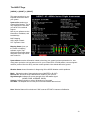
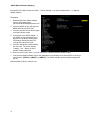
The ABOUT Page
[CHECK] -> [MAINT] -> [ABOUT]
This page contains a lot very
important information about
your system.
System Info contains your
system Serial Number. This is
very important to have when
you call AFS for technical
support.
Next is your software version
information, IP address, and
installed keys.
MAP: Mapping
AOA: Angle of Attack
SVT: Synthetic Vision
Mapping Status gives you
the version of mapping
software, region, map
effective and expiration dates,
and status of the map Vector
and Terrain file.
System Status contains information related to how long your system has been powered-on for, how
many power cycles the unit has had over its life, your current GPS LAT/LON position, current magnetic
variation (received from the GPS), and the current synthetic vision altitude above the ground.
Weather Status shows information for diagnosing XM or ADS-B Weather module problems.
Mode: Shows the mode of that particular screen (MASTER or SLAVE).
Receiver ID: Shows the unique identification number of your receiver
Signal Strength: Indicates the current strength of the XM satellite signal
(NONE, POOR, AVERAGE, GOOD)
Antenna: Indicates whether or not an XM antenna is connected
Last Data: The elapsed time from the point of the last weather data received.
Note: Weather Status will not be shown if WX is set as OFFLINE in Instrument Calibration.
43
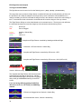
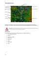
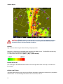
Moving Map Display
GPS Track
Current Waypoint
Current Zoom Level
METAR Symbol
Class D Airspace
Top
Future TFR from XM
Major Road
VOR
Intersection
Map GPS Source
XM Weather Age
The system can display a moving map if you have purchased and installed the optional Mapping
package. You will need to have the SD card installed with the mapping database for proper operation.
WARNING: The moving map is to be used as a reference only and is not to be used in place
of current aviation charts or for primary navigation.
Map Features
Currently the map will display the following features for the United States Only:
1. Public and Private airports
2. Airspace
3. Intersections, VOR’s
4. Obstructions
5. State Lines
6. Rivers
7. Major Roads
8. Cities
44
The moving map can be displayed as a partial screen along with the EFIS and/or Engine Monitor or as a
complete page. You can also select if the airspeed and altitude tapes and engine monitor are displayed on
the map from the [MAP] -> [SETTINGS] menu and selecting the [AIR OFF] [Engine] buttons.
EFIS-Engine-Map Page
Map Page Air & EMS OFF
Map Page with Air ON EMS ON
Map Data Source
The current flight plan source that is displayed on the Map can be set from the following menu:
[MAP] -> [SETTINS] -> [SRC/???] where SRC/??? Can have the following options depending on the radios
installed in the aircraft:
SRC/GNAV1
430W/530W/480 GPS Navigator Radio setup as GPS 1
SRC/GPS2
External GPS unit setup as GPS 2
SRC/MAP
Flight Plan activated from the EFIS Map
Private Airports
The [MAP] -> [SETTINGS] -> [MORE] -> [PVT ON/OFF] button gives you the option of displaying or not
displaying private airports on the moving map screen.
Intersections
The [MAP] -> [SETTINGS] -> [MORE] ->[INTS ON/OFF] button gives you the option of displaying or not
displaying Intersections on the moving map screen.
Zoom Range
The current zoom rang is displayed by an arc on the top of the map display with its current digital range. The
zoom range can be adjusted using the knob anytime [ZOOM] is displayed. The map software will
progressively declutter airports, intersections and obstacles from the screen as you zoom out farther.
Nearest Airport
Pressing the [NRST] button from the map menu will bring up a sorted list of the nearest eight airports
displayed on the screen at the current zoom level. If you want to see the actual closest airports you should
zoom in before pressing the [NRST] button. You can then use the knob so select the desired airport.
Pressing the [INFO] button will display the information for the highlighted airport.
CAUTION If you want to see the actual closest airports you should zoom in before pressing the [NRST]
button.
Direct To Navigation
Pressing the [-D->] button from the map menu will enable you to select the desired airport to navigate to by
using the knob.
Airport Info
Pressing the [INFO] button from the map menu will bring up multiple pages of airport info, including runways,
frequencies and airport information.
Airspace
Airspace is displayed on the moving map along with it vertical boundaries in a similar format to a sectional
chart.
Track Mode
The desired map track mode can be selected from the [MAP] -> [SETTINGS] menu and selecting either [TRACK
UP] or [NORTH UP]
46
Map Database Files
The moving map uses the following database files stored on the SD card, the SD card
must be kept in the EFIS for the map to work. :
AFS USA Data Files
AF-3400 & AF-3500 non “S” CPU (OLD Systems)
File Name
Description
Update Frequency
AFSTERUS.AFM
AFSVECUS.AFM
AFSMAPUS.AFM
Terrain height information for the US
Vector data for US roads/rivers/lakes/cities
Navigational data (airports, obstacles, navaids, …)
When Required
When Required
Every 28 Days
AF-3400s, AF-3500s, AF-4500s “S” CPU (New Current Systems)
File Name
Description
Update Frequency
AF2TERUS.AFM
AF2VECUS.AFM
AF2MAPUS.AFM
Terrain height information for the US
Vector data for US roads/rivers/lakes/cities
Navigational data (airports, obstacles, navaids, …)
When Required
When Required
Every 28 Days
Worldwide Jeppesen Data Files
The Terrain and Vector files are provided by Advanced Flight Systems and are rarely updated. The MAP files
are provided by Jeppesen and install on the SD card using their JSUM program.
AF-3400 & AF-3500 non “S” CPU (older systems)
File Name
Description
Source
AFSTERxx.AFM
AFSVECWW.AFM
AFSMAPxx.AFM
Terrain height information for the US
Vector data for US roads/rivers/lakes/cities
Navigational data (airports, obstacles, navaids, …)
AFS Web Store
AFS Web Store
Jeppesen JSUM
AF-3400s, AF-3500s, AF-4500s “S” CPU (New Current Systems)
File Name
Description
Source
AF2TERxx.AFM
AF2VECxx.AFM
AF2MAPxx.AFM
Terrain height information for the US
Vector data for US roads/rivers/lakes/cities
Navigational data (airports, obstacles, navaids, …)
AFS Web Store
AFS Web Store
Jeppesen JSUM
xx
Region Code for your area.
AF
AS
EU
ME
NA
SA
PA
Africa
Asia
Europe
Middle East
North America
South America
Pacific
47
AFSMAPUS.AFM and AFSVECUS.AFM files have a version number associated with them, and will only
work with a version of the system software that is compatible. When you download the map files, make sure
that your version of the system software matches the map version. If it doesn't match, the map will not work.
Example:
AF3000 Series System Software Version 7.7.15-MV15
<-The MV15 is the map version
Map Data files Version MV15
Map Database Update Procedure
1. Format SD Card
Format the SD card on your PC for “FAT32”. Right click your SD drive icon and click on format. You
should also make sure it is set for FAT32.
2. Download current Map database files
Go to our website under the Store header -> Map Data.
www.Advanced-Flight-Systems.com
Right click the zip file and select Save Target As, select your desktop as the target location and click Save.
Once the file has been downloaded, extract the 3 files within the zip file to your freshly formatted SD Card.
Once you are finished you should have the following three files on your SD card:
AFSMAPUS.AFM
Airport and Airspace data
AFSTERUS.AFM
Terrain data for the USA
AFSVECUS.AFM
Roads, Rivers, Lakes and Cities
3. Install SD Card into EFIS
4. Verify the Effective and Expiration Dates are correct on the I Agree screen
48
Traffic Display
WARNING: Traffic information displayed on the Map is provided for visually assisting in acquiring
other aircraft. The aircraft should be maneuvered based only upon ATC guidance or positive visual
acquisition of conflicting aircraft.
Traffic 1,100ft above
CAUTION Traffic same
Altitude
Traffic 1,200ft above
descending
The AFS-Map can display traffic when connected to a NavWorx ADS600-B, Garmin GTX-330, or Zaon XRX.
Traffic Display on the Map
Traffic is displayed using the standard TCAS-II symbology
Other Traffic (Greater than 7000ft relative altitude and greater than 7nm range)
Proximity Traffic (within 1200ft relative altitude and less than 6nm range)
Traffic Advisory (within 1200ft relative altitude and less than 0.2nm range)
49
Zaon XRX
XRX detects up to three threat aircraft from within your cockpit using a cutting-edge, proprietary, self-contained antenna
design. With direction, locating and identifying traffic is simple and easy, and traffic information is displayed on the EFIS
Map page. XRX delivers the three "dimensions" of traffic information that pinpoints where traffic is located: direction,
range and relative altitude. Traffic accuracy is 0.2 NM on average for range, ±200 ft for altitude (defined by TSO
standards set for transponder encoders), and ±22° for direction. For detailed Zaon information and capabilities:
www.zaon.aero
Zaon EFIS Setup
After connecting the Zaon XRX to EFIS serial port #2 you will need to configure the serial port in the EFIS for
ICARUS/TRFC. You will also need to configure the Zaon output to Garmin Traffic mode.
Garmin GTX-330
The IFR-certified GTX 330 offers a Traffic Information
Services (TIS) interface, giving you greater traffic
awareness in some of the United States's busiest
airports. TIS traffic from the GTX330 is displayed on the
map, including location, direction, altitude and
climb/descent information for nearby aircraft.
GTX-330 EFIS Setup (hold FUNC + ON keys)
After connecting the GTX 330 Serial port #1 to EFIS serial port #2 you will need to configure the serial port #2 for
ICARUS/TRFC
EFIS Main Harness
GTX-330
EFIS Configuration
GTX330 Configuration
13
25
22
23
ICARUS/TRFC
ICARUS/TRFC
ICARUS ALT
REMOTE + TIS
ADS-B Traffic
ADS-B is only compatible with s-CPU units.
The NavWorx ADS600 series ADS-B equipment can be directly
interfaced to your EFIS. The ADS600 UAT receiver displays ADS-B
information including TIS-B traffic and FIS-B weather. The ADS600-B
UAT Transceiver displays the same information but also transmits your
position to the ADS-B system. ADS-B is a free service provided by the
FAA that transmits weather and traffic information to aircraft with
compatible receivers. With a transceiver, aircraft can participate in the
system by transmitting their position to the ADS-B system for the benefit
of other aircraft and ATC.
ADS600 (-B) Setup
Connect the NAVWORX device to your EFIS in accordance with the
NavWorx installation manual. The ADS600-B Display Port can connect to
any available AFS serial port. The ADS600-B Altitude Encoder Port
should connect to AFS serial port #2. It is important to have the
NavWorx maintenance port connected to a DB9 connector. This will allow
for future software updates and to setup/configure the ADS-B box.
Configure Serial Port #3 for ADSB57K and Serial Port #2 for TFC/ICARUS
EFIS Main Harness
13
5
4
21
Serial #2
Serial #3
Serial #3
Serial #3
TX
RX
TX
GND
ADS600(-B) P1
7
5
24
23
EFIS Configuration
ICARUS/TRFC
ADS-B
ADS-B
ADS-B
Use the NavWorx manual to connect to its maintenance port. The following three commands must be entered into the
NavWorx box: 1. SET PROTOCOL TA, 2. MAP TA RS232, 3. SET BAUD 57600.
To prevent seeing yourself called out as traffic (ghosting), connect one of the Serial outputs of the GTX-330
configured as REMOTE + TIS to Pin 33 of the ADS600-B box. Send the following command to the ADS600-B.
TXCP GTX330 or TXCP GTX327.
50
Garmin GTS-8xx TCAS System
The Garmin GTS-8xx TCAS System is a fully self-contained active traffic system which will interface to your
EFIS display. Please see the Traffic ARINC Adapter Wiring Diagram for wiring and configuration.
ARINC output speed on the GTS-8xx MUST be configured for LOW speed!
Note: A special TCAS ARINC adapter is required, please contact AFS for more information.
51
Weather Display
CAUTION: NEXRAD weather data should only be used for long-range planning purposes.
Inherent delays and relative age of the WX data can be experienced. NEXRAD weather
cannot be used for short-term weather avoidance.
NEXRAD
High resolution radar image of radar reflectivity and lighting strikes.
Reflectivity is the amount of transmitted power returned to the radar receiver. The NEXRAD colors directly
correlate to the level of detected reflectivity from the radar.
To enable/disable NEXRAD press [MAP] -> [WX] -> [NXRD ON/OFF]
NEXRAD DATA AGE
The current age of the NEXRAD data is shown in the lower right hand corner of the map, 4 minutes old in
this example.
NEXRAD LIMITATIONS
• NEXRAD base reflectivity does not provide sufficient information to determine cloud layers or precipitation
characteristics. You cannot distinguish between wet snow, wet hail, and rain.
52
• NEXRAD base reflectivity is sampled at the minimum antenna elevation angle. An individual NEXRAD
site cannot depict high altitude storms at close ranges. It has no information about storms directly over the
radar site.
• When zoomed in a square block on the display represents an area of 2 ½ miles. The intensity level
reflected by each square represents the highest level of NEXRAD data sampled within the area.
METARS
Airports with METAR data are displayed with a colored flag next to the airport symbol on the map.
If an airport has METAR data a weather
page will be added to the airport info after
the frequency page, usually page 2.
TAF's
Airports with TAF's will have a special "T" symbol next to the airport on the map page. In additional, there will
be a TAF button on the airports info page. TAF's are given in their original coding.
TFR’s
Active TFR’s are drawn in RED and future TFR’s are YELLOW. Your screen will remember the last TFR's
displayed upon shut-down so those that remain active are displayed at the next power-up (before XM WX
comes online). This is done by saving all TFR's onto the SD Card as a file named "TFR.xml". If a TFR
becomes inactive before the next power-cycle, that TFR will not be displayed. Similarly, if a future TFR
becomes active before the next power-cycle, that TFR will be displayed.
Lightning
Lightning is displayed as lightning bolts as part of the NEXRAD weather display.
To enable/disable Lightning press [MAP] -> [WX] -> [LGHT ON/OFF]
Winds Aloft
Winds aloft are displayed over the map page using standard NOAA barbed symbols. To change
the altitude, use the right knob to select WNDS as the function. Altitudes are given in Flight Levels
(i.e. FL120 is 12,000ft)
To enable/disable Winds Aloft press [MAP] -> [WX] -> [WNDS ON/OFF]
XM Weather
Weather Module installation
The WeatherWorks XM Weather Module should be mounted on the inside of the aircraft and the antenna
located on the aircraft glare shield. The XM Weather module should be powered from a 12V aircraft source.
The weather receiver communicates with the EFIS screens using the Ethernet port. For a dual screen
53
installation you will need to use a separate Ethernet hub in the aircraft. If you have a single screen system
you can plug the weather receivers Ethernet cable directly into the EFIS.
Screen Configuration Settings
One of the screens in the aircraft needs to be configured as the Weather Master and any additional screens
should be set to Slave or Offline.
Currently we do not support weather on both the new “s” CPU along with the older non “s”
CPU on the same network. You should pick one system to make the master and configure
the other system as Offline.
The screen with the Engine Monitor connections should be configured as the Weather Master in the ADMIN
settings menu of calibration.
1. Admin Settings
18. WX Module Config
MASTER
Any additional screens should be configured as a Weather SLAVE in the ADMIN settings menu of
calibration.
1. Admin Settings
18. WX Module Config
SLAVE
Network Ethernet hub
We recommend a Linksys 5-Port 10/100 Switch Model SE2500, this is a 12V powered unit.
XM Weather Service
After the installation is complete and you are able to move the aircraft outside so that the Antenna can
receive the Satellite signal you will need to call XM to subscribe to a service plan. Currently the AFS
software will display the following items from the “Aviator LT” XM WX Data Packages: NEXRAD, TFR's,
METAR's, TAF's, and Lighting.
Note: Non-s CPU units cannot display TAF's due to hardware limitations.
You will need your radio ID Number from the receiver when calling XM at the following number:
XM Activation 1-800-985-9200
XM Diagnostics
The XM status message and logo will indicated the current XM receiver status using the following messages:
Screen is searching for weather receiver.
Screen is waiting for the XM data for the first time since turning on.
The age of the displayed XM data
54
XM Weather Diagnostics
[CHECK] -> [MAINT] -> [ABOUT]
The ABOUT page displays pertinent information about the status of your XM Weather receiver.
Weather Status shows information for diagnosing weather module problems.
Mode: Shows the mode of that
particular screen (MASTER or
SLAVE).
Receiver ID: Shows the unique
identification number of your receiver
Signal Strength: Indicates the
current strength of the XM satellite
signal
(NONE, POOR, AVERAGE, GOOD)
Antenna: Indicates whether or not an
XM antenna is connected
Last Data: The elapsed time from the
point of the last weather data
received.
Note: Weather Status will not be
shown if WX is set as OFFLINE in
Instrument Calibration.
ADS-B Weather
Automatic Dependant Surveillance Broadcast is part of the FAA NEXTGEN system to increase aviation
safety and awareness within the national aerospace system. One of the two products ADS-B provides is a
free weather uplink service which includes the following products: METAR's, TAF's, TFR's, Winds Aloft and
Lightning.
ADS-B Hardware
Current y AFS supports the NavWorx ADS600-B transceiver.
Installation
Please see Page 43 for installation details.
Screen Configuration Settings
Once the ADS600-B is installed and configured, the map page needs to be setup to view ADS-B weather
information.
To enable ADS-B Weather go to any map page and press [SETTINGS] -> [WX] -> [WX: ADS-B]
The various weather products can also be turned on or off on that same WX menu.
NXRD - NEXRAD Radar
55
LGHT - Lighting Strikes
WNDS - Winds Aloft
METAR's, TAF's, and TFR's are always on and not user selectable.
ADS-B Status Information
[CHECK] -> [MAINT] -> [ABOUT]
The ABOUT page displays pertinent information about the status of your ADS-B Weather receiver.
Weather Status - Shows status information about the ADS-B interface.
Not Parsing ADS-B Weather - The EFIS is not receiving FIS-B weather data
ADS-B Mode - Displays either Master or Slave mode (Unit wired to the ADS-B device will be Master)
Ownship Count - Number of messages the EFIS is receiving from the ADS-B device. Verifies connectivity
Aged Times - Elapsed time since the last data update (METAR, TAF, TFR, NEXRAD, Winds, Lighting)
56
IFR Approach Plates
The EFIS Map page has the ability to display an IFR approach plate if your data card contains a CHARTS
directory and you have the approach plate file for the selected airport. Current approach plates are available
for purchase from the Advanced Flight Systems web store. www.Advanced-Flight-Systems.com
The AFS approach plates are geo-referenced and should display your current aircraft position if your location
is on the approach plate area. If you have a traffic receiver, traffic should be displayed on the approach plate.
If the selected chart has the geo-referenced data, it should show a green box around the airspace and a
magenta circle located on the airport. If the magenta circle is not on the airport, you should not use the
approach plate for aircraft position.
WARNING: It is the users responsibility to verify that the approach plates in the EFIS are current
and up to date before using.
The CHART button is available from the MAP [–D->] or Nearest menu and will bring up the first chart for the
selected airport if the data is on the SD card. Once you have displayed a chart, the screen will remember
the current chart and pan position so that you can easily flip back and forth from the map. Use the [PREV]
and [NEXT] buttons to select the available charts and the knob to pan the chart up and down.
57
58
Engine Monitor Display
The system can display the engine monitor on the bottom of the main EFIS page or as a full Engine page if
the system has one of the following:
1. The screen has an engine monitor board installed in the case.
2. The screen is connected to another screen that has an engine monitor board installed with an
Ethernet crossover cable.
Fuel Computer
The fuel computer is accessed from the main screen by pressing the [ENGINE] button followed by pressing
the [FUEL] button.
WARNING
The GALS USED (Gallons Used) and GALS REM (Gallons Remaining) displayed is not a
measurement of the fuel in the aircrafts tanks. The fuel amount calculated from the starting fuel level you
programmed in the system, minus the fuel used while the engine was running. When the system is properly
calibrated and fuel is added correctly the system will accurately measure the fuel used. It is imperative the
pilot verify the calibration of the system over many tanks of fuel before using the "GALS REM" and/or "GALS
USED" Modes as an indication of the fuel in the tanks or fuel used. Even after verifying the calibration of the
system it should never be used as the primary indicator of fuel quantity in the tanks. It is important the pilot
visually check/measure the fuel quantity for each tank before takeoff and crosscheck these readings against
the Fuel Level Gauges and the Fuel Computer. It is important the pilot use preflight and flight planning
techniques, in accordance with the FAR's, which will help insure the proper amount of fuel for the intended
flight is on board the aircraft before takeoff. While in flight the fuel gauges and fuel computer should only be
used to crosscheck the fuel calculations of the fuel onboard from flow rates specified in the specification for
your aircraft and calculations of the fuel onboard from flow rates that you measured from previous flights.
The use of this system does not eliminate or reduce the necessity for the pilot to use good flight planning,
preflight and in-flight techniques for managing fuel. If you are not familiar with these techniques, contact the
FAA to acquire proper training.
59
Fuel Flow Calibration
The accuracy of the fuel computer is affected by the value of Counts per .01 gals (K Factor). The Counts per .01 gals
(K Factor) sets the calibration of the instrument to match the flow transducer and the variations in the installation. After
running a tank of fuel use the following formula to adjust the accuracy.
The Counts per .01 gals (K Factor) is adjusted from the Fuel Flow/Computer page in Instrument Calibration.
New Counts per .01 gals = (Old Counts per .01 gals) x (Disp GAL USED/PUMP GALS)
Fuel Computer Modes
The fuel computer display can set to display any of the following by pressing the [MODE] button. The mode label will be
RED if the fuel computer gallons remaining amount does not match the fuel tanks.
Gallons Used -> Gallons Remaining -> Hours Remaining
If the system is connected to a GPS you will also have:
Kts per Gallon -> Miles per Gallon -> Gallons Remaining at Waypoint -> Gallons Required to Waypoint
WARNING: The Fuel Computer is only accurate when the fuel-flow sensor is calibrated properly and fueling stops are entered
correctly.
GAL USED
Gallons Used
Displays the gallons used since the last time the fuel computer was set.
GAL REM
Gallons Remaining
Displays the gallons remaining, calculated from the last time the fuel computer was set.
HRS REM
Hours Remaining
Displays the hours remaining, calculated from the last time the fuel computer was set and the current fuel flow rate.
WARNING!! The following are based on the current fuel flow and the GPS ground speed. If you change
power settings or the Winds change they will not be correct!
NM/GAL
Nautical Miles per Gallon
Displays the current ground distance traveled in nautical miles per gallon of fuel.
SM/GAL
Statute Miles per Gallon
Displays the current ground distance traveled in statute miles per gallon of fuel.
GREM AT
Gallons Remaining At Waypoint
Displays the fuel amount that should be remaining at the next GPS waypoint.
GREQ TO
Gallons Required to next Waypoint.
Displays the fuel amount of fuel needed to get to the next GPS waypoint. This is based on the current fuel flow and GPS
data.
Adding Fuel to the Fuel Computer
WARNING: Every time fuel is added or removed from the aircraft tanks one of the following operations must be
done to protect the accuracy of the fuel computer.
60
TANKS FILLED
You can set the fuel computer to the programmed full tanks by pressing one of the following buttons in the
fuel computer:
1. [FILL MAINS] If only the main tanks have been filled
2. [FILL ALL]
If the main and tip tanks have been filled
WARNING: If you press [FILL ALL] and have not added fuel to the tip tanks the fuel computer calculations will be
incorrect
You can add or subtract fuel to the computer by adjusting the [KNOB] for the correct amount and then
pressing the [ADJ] button.
% Power Display
The system will display the estimated %Power using the Horsepower table in instrument calibration. You will
need to configure the settings by using the appropriate data from your engine manual.
61
The following data is supplied only as a reference; you should use your Lycoming engine graphs to verify the
accuracy of the display. The Delta HP number is the increase in actual HP that the engine will produce for
the same manifold and RPM at increased Altitude.
Engine Rated HP RPM 2000 2100 2200 2300 2400 2500 2600 2700 Engine Rated HP RPM 2000 2100 2200 2300 2400 2500 2600 2700 Engine Rated HP RPM 2000 2100 2200 2300 2400 2500 2600 2700 62
O‐360 180 55% 75% MAP MAP 21.6 26.7
21 26
20.3 25.2
19.8 24.6
19.2 23.9
18.9 23.5
18.6 23.2
18.2 22.7
O‐320 160 55% 75% MAP MAP 21.4 26.4
20.8 26
20 25.6
20.3 24.9
19.6 24.3
19.2 23.8
18.8 23.2
18.4 23.1
IO‐540 260 55% 75% MAP MAP 23.2 29.4 22.4 28.1 21.5 26.8 20.7 25.7 19.8 24.7 19.3 24 18.8 23.3 18.5 22.5 Altitude
2000
4000
6000
8000
10000
12000
14000
Delta HP 2.3
4.6
6.9
9.1
11.4
13.7
16
Delta HP Altitude
2000
4000
6000
8000
10000
12000
14000
Altitude
2000 4000 6000 8000 10000 12000 14000 Delta HP 5 9 13 17 21 25 29 2
4.1
6.1
8.1
10.1
12.2
14.2
EGT/CHT Display Modes
The Exhaust Gas Temperatures (EGT) and Cylinder Head Temperatures (CHT) for every cylinder are
continuously displayed in both analog and digital formats on the AF-3400/3500. The cylinders are laid out
sequentially with cylinder #1 on the left followed by cylinder #2 to its right and so on. The graph uses small
white bars for the CHT that are superimposed onto the larger EGT bars. The graph uses a dual scale that
represents the CHT scale on the left side and the EGT scale on the right. The digital reading for each
column is displayed above each bar for CHT and below for EGT. During normal operation the EGT and CHT
bars will align themselves in a very easy to recognize pattern.
Leaning EGT Mode (Peak Detect)
The leaning peak detection mode is selected from the main screen by pressing the [ENGINE] -> [EGT/CHT]
-> [PK DET OFF] buttons. As you lean the engine, the EGT bars for all cylinders will rise. As each cylinder
reaches peak EGT, a tattletale marker will appear at the top of that cylinder’s bar. The current EGT is shown
on the bottom of the bar, Peak EGT is displayed on the top and the degrees rich or lean of peak are
displayed on the bar. If you start to richen the engine before all cylinders have peaked the unit will detect the
EGT drop and display a false peak. The peak detection can be reset at any time by pressing the [PK DET
ON] then [PK DET OFF] button.
Warning: You should never lean your engine with power settings over the factory
recommended level (generally 65% to 75% power).
Leaning with high power settings can cause detonation. Always verify your power level with engine charts
before leaning. As you lean past maximum horsepower (100F to 150F rich of peak EGT) your engine will
lose power.
Flight Times
Flight times are displayed on the top of the maintenance check list page. Press the [CHECK] button followed
by the [MAINT] button.
Tach Time:
Hours on engine above 1250 RPM.
Hobbs Time:
Hours on engine above 0 RPM.
Last Flight:
Hobbs time for the last flight.
Today:
Hobbs time since 12:00 AM today.
Check Lists
To view your checklists pages press the [CHECK]
button from the main screen. Use the [NEXT] and
[PREV] buttons to scroll through the checklists. To
return to the main screen press the [RETURN]
button.
63
If the [CHECK] button is pressed the page that is displayed is controlled by the following:
ENGINE RPM
PAGE
Normal Use
0
1
Before Starting Engine
<1250
3
Before Takeoff Checklist
>1250
6
Emergency Checklist
This will make the emergency procedures check list easy to access in the event of an in flight emergency.
The checklist file is stored in the CHKLST.AFD file and can be transferred using the SD card from the EFIS Calibration
Menu (CHECK -> MAINT -> ADMIN ->CALIBRATION).
1. Admin Settings
1. Transfer Files
2. Checklists file
Rotate the right knob to BACKUP and press START
The text for the checklists is stored in the following format and can be modified using Microsoft Word Pad on a PC.
# Lines are limited to 96 char long
#
# DO NOT USE COMMAS IN THE CHECKLIST TEXT !
CHKLST0.TITLE, BEFORE STARTING ENGINE
CHKLST0.LINE1, Preflight Complete
CHKLST0.LINE2, Spar Pins Secured - CHECK
CHKLST0.LINE3, Safety Belts - ON
CHKLST0.LINE4, Doors - LATCHED
CHKLST0.LINE5, Fuel Selector Valve - DESIRED TANK
CHKLST0.LINE6, Avionics - OFF
CHKLST0.LINE7, Brakes - SET
CHKLST0.LINE8, Circuit Breakers - CHECK IN
CHKLST0.LINE9,
CHKLST0.LINE10,
CHKLST0.LINE11,
CHKLST0.LINE12,
CHKLST1.TITLE,
CHKLST1.LINE1,
CHKLST1.LINE2,
CHKLST1.LINE3,
CHKLST1.LINE4,
CHKLST1.LINE5,
CHKLST1.LINE6,
CHKLST1.LINE7,
CHKLST1.LINE8,
CHKLST1.LINE9,
ENGINE STARTING
Mixture - RICH
Prop - HIGH RPM
Master Switch - ON
Fuel Boost Pump (3 Sec)
Flaps - UP
Throttle - OPEN approx 1/4
Propeller Area - CLEAR
Ignition Switch - START
Oil Pressure – CHECK
CHKLST1.LINE10, Strobes - ON
CHKLST1.LINE11,
CHKLST1.LINE12,
CHKLST2.TITLE, BEFORE TAKEOFF 1/2
CHKLST2.LINE1,
CHKLST2.LINE2,
CHKLST2.LINE3,
CHKLST2.LINE4,
Brakes - SET
Spar Pins Secured - CHECKED
Doors - LATCHED
Flight Controls - FREE & CORRECT
CHKLST2.LINE5, Flight Instruments - SET
CHKLST2.LINE6, Altimeter - CORRECT PRESSURE
CHKLST2.LINE7, Fuel Selector Valve - DESIRED TANK
CHKLST2.LINE8, Mixture - RICH (below 3000ft)
CHKLST2.LINE9, Elevator and Aileron Trim - NEUTRAL
CHKLST2.LINE10, Throttle -- 1800 RPM
CHKLST2.LINE11, ...Magnetos - CHECK (175 max drop)
CHKLST2.LINE12, ...Prop - CHECK OPERATION
.
64
To restore the checklist file to your EFIS perform the same steps above but instead rotate the right
knob to say RESTORE and press SELECT.
Maintenance Log
The system has an Aircraft Maintenance Log that can be setup to track any number of user configurable items. Each
item can be configured as a Tach time or calendar time controlled event. Once the time interval has expired the item will
turn red indicating the need for service.
You can set any items Date and Tach Time to
the current values from the Aircraft Maintenance
page: [ADMIN] -> [UPDATE] buttons.
The Maintenance Log is selected from the
following menu:
[CHECK] -> [MAINT]
The Maintenance settings are controlled by the
file:
MAINT.AFD
The file is in the following format and can be
modified using Microsoft Word Pad on a PC.
Units must be Tach hours or days.
DESC, Annual Inspection
LASTDATE, 08-05-2006
LASTTACH, 210.80
INTERVAL, 250
UNITS, tach hours
NEXTLINE, 0
DESC, Tires
LASTDATE, 04-05-2005
LASTTACH, 95.10
INTERVAL, 365
UNITS, days
NEXTLINE, 0
DESC, Oil and Filter
LASTDATE, 06/19/2006
LASTTACH, 195.30
INTERVAL, 100
UNITS, tach hours
NEXTLINE, 0
DESC, ELT Batteries
LASTDATE, 08/05/2006
LASTTACH, 210.80
INTERVAL, 400
UNITS, days
NEXTLINE, 0
DESC, Insurance
LASTDATE, 08/05/2006
LASTTACH, 210.80
INTERVAL, 180
UNITS, days
NEXTLINE, 0
You can transfer the file to and from the SD card from the EFIS Calibration startup screen (CHECK -> MAINT
-> ADMIN ->CALIBRATION).
1. Admin Settings
1. Transfer Files
3. Maintenance
65
Rotate the right knob to BACKUP (if you want to copy it to your SD card) or RESTORE (if you want to copy
the file from your SD card to your EFIS) and press START
Weight & Balance Screen
The Weight & Balance page is selected from the following
menu:
[CHECK] -> [MAINT] -> [BALANCE]
The PREV & NEXT buttons are used to select the station and
the knob is used to adjust the weight of the station or volume
for fuel.
The Weight & Balance settings are controlled by the files:
AIRCRAFT.AFD Stations, Weights, Screen Location
AIRCRAFT.AFB Standard .BMP of the aircraft picture.
You can transfer the files to and from the SD card from the
EFIS Calibration startup screen (CHECK -> MAINT ->
ADMIN ->CALIBRATION).
1. Admin Settings
1. Transfer Files
4. Weight & Balance
The normal weight & balance settings can be adjusted on the
Weight & Balance page by pressing the [STATIONS] button.
The X and Y on the stations page is the screen coordinates for
the text on the aircraft bitmap. The Aircraft Type, Gross Weight
and CG Range will need to be modified using Microsoft Word
Pad and editing the AIRCRAFT.AFD file on a PC.
The aircraft bitmap can be changed using Microsoft Paint and
editing the AIRCRAFT.AFB file, do not change the overall
dimensions of the Bit Map.
66
Flight Data Logs
Flight Data from the system is downloaded using the SD data card from the Maintenance checklist page. To
download flight data do the following:
1. Place an SD card in the Screen
2. Press [CHECK] -> [MAINT.] -> [ADMIN] -> [DATA LOGS]
3. The last flight time will be displayed over the knob; you can select the amount of flight time to
download using the knob. (Rotate it to the right to increase time with a max. of 12hrs)
4. Press [START] to transfer the selected stored flight data onto the SD Card.
Importing Flight Data to Excel
Once you save data from the Engine Monitor you can import the data into Microsoft Excel by the following
procedure:
1. From Excel select File Open
2. Change the file type to All Files (*.*)
3. Open your SD drive folder
4. Select the *.ALD file to open. The data files are stored using the following name:
ymmddhhm.ALD where
y
year
mm
month
dd
date
hh
hour
m
minute
5. The Text Import Wizard should start and look like this:
Select Delimited
Click Next
Select Comma
Click Finish
67
AF-3400/AF-3500/AF-4500 Installation
Mechanical Mounting
The Display should be mounted from the rear of the instrument panel with four 6-32 screws. Allow clearance
for the connectors on the rear. See the Appendix B: for proper dimensions. The rear connectors are 5.5”
from the front panel and the plugs require another 3” for clearance. The case ground screw in the middle of
the decal should be connected to the main aircraft ground buss with a #18 agw wire.
Case Ground Screw
68
Electrical Connections
For wiring information see APPENDIX M:
The AF-3000/4000 series power requirement is 12 volts at 2.5 Amps, a 3 amp circuit breaker or fuse should
be used for the system.
All wire should meet Mil Standard MIL-W-22759/16 (Tefzel insulation)
20 AWG wire is normally sufficient for the power supply and ground wires.
Pin 1
Red
Master Power
Pin 3
Black
Ground
*Pin 15 N/C
Backup Power
*Backup Power input is used for a dual electrical system.
CAUTION: The screen case and sensors must have a good ground to the aircraft battery. The case
grounding screw should be connected with at least a 20 agw wire to the main aircraft ground buss.
Audio Connections
If two EFIS units are being installed, the audio from only 1 units needs to be connected. All alerts are passed
through the Ethernet network.
The harness is wired for a 560-ohm audio output that allows you to match the output impedance of the
system to standard aircraft audio panel and intercom audio devices. If your radio or audio panel does not
have an unswitched audio input you will need to purchase a audio mixer. Do not attempt to connect the
EFIS audio to a music input on an intercom, they are not the same impedance and it will not be loud enough.
Do not attempt to connect the EFIS audio along with a com radio to the same intercom input.
We recommend the following audio mixer if you do not have an audio panel:
http://www.fdatasystems.com/AP_60.htm
For wiring information see APPENDIX M:
Volume Adjustment
The volume can be adjusted from Instrument Calibration.
32. Test Audio
The range is (0%-100%) and is adjusted using the knob followed by pressing the [SAVE] button. The Test
Audio menu will play all the sounds in the system.
69
EFIS Serial Data Connections
Each AF-3400/3500/4500 screen has four serial ports that can be used for external equipment (GPS, NAV,
Traffic, FADEC Engine, ect..) communication. Not all functions are available on all serial ports so you should
review the options before wiring external equipment to a serial port.
If you have more than one screen installed in your aircraft and they are connected with Ethernet you can
share the serial ports between screens. For the serial ports and navigation sources (GPS, NAV) to work
properly you will need to configure the actual serial port number hardware settings as well as assign an EFIS
navigation source to a serial port number. The following steps should be followed in order:
STEP 1
Serial Port # Function Hardware Setup
This is where you configure each serial port for the external device that is physically wired to the port. You
will need to know which serial port each device is wired to on the screen and what the external devices
communication settings are. From [Instrument Calibration] mode you should select the following menu to
configure each Serial Port:
[1. Admin Settings] ->
Serial Port #
Serial Port #1-4 Functions
Options
Notes
DISABLED
Ext. AHRS
NMEA @ 4800
TRFC/ICARUS
SL-30
ARINC
AVTN/CHELTON
AVTN/ARNAV
FADEC SBC-100
FADEC SBC-250
OP TECH
NMEA/AVTN
TRFC/SHADIN ALT
GARMIN AT
MAGELLAN
NORTHSTAR
AFS GPS
TRAFFIC
AVTN/AVTN
VPX
COGUARD
ADSB
Nothing wired to port
External AHRS input
External GPS with NMEA @ 4800 baud
Garmin Traffic In / ICARUS Out
Garmin SL-30 radio connected
AF-ARINC module connected to port
Chelton Engine Data Out
430W/530W or GPS with Aviation format
FADEC Data In
Do Not Use
OP Engine Data Out
NMEA 9600 In / AVIATION Out
Garmin Traffic In/ SHADIN Out
Garmin AT format, Dynon gray code converter
Transponders set to MAGELLAN format
Transponders set to NORTHSTAR format
AFS GPS
Garmin Traffic format (GTX 330, Zaon, ADS-B)
Aviation In / Aviation Out
Vertical Power VP-X Interface
CO Guardian Interface
NavWorx ADS-B Interface
NOTES: STEP 1 should be done for all screens in the aircraft and only configured for the equipment
that is physically connected to that screens serial ports.
STEP 2
GPS/NAV # Data Source Software Setup
This is where you configure the three available EFIS CDI and Moving Map data sources (GPS/NAV 1,2,3) to
their assigned serial ports. The data sources for multiple screens must be configured to the same navigation
source. If you configure GPS/NAV1 as Serial Port 4 (ARINC Module connect to Port #4) on the left screen
the right screen must be set GPS/NAV1 as Remote ARINC. This configures the EFIS to read the data from
the ARINC port anytime GNAV 1 is selected from either screen.
From [Instrument Calibration] mode you should select the following menu to configure each GPS/NAV Data
Source:
70
[1. Admin Settings] ->
GPS/NAV #
Options
10. GPS/NAV 1-3 Data Source*
NONE
Serial Port #1
Serial Port #2
Serial Port #3
Serial Port #4
Remote GPS
Remote ARINC
Remove NAV
Notes
No connected Nav or GPS
GPS or Nav Radio Connect to Serial Port #1
GPS or Nav Radio Connect to Serial Port #2
GPS or Nav Radio Connect to Serial Port #3
GPS or Nav Radio Connect to Serial Port #4
GPS connected to remote screen
GPS/NAV connected to remote screen ARINC
SL-30 connected to remote screen.
NOTES:
*If you have an ARINC module it must be configured as the GPS/NAV1 Data Source.
**If you have a second ARINC module it must be configured as the GPS/NAV2 Data Source.
Depending on the type of Nav Radio connected to the GPS/NAV data source it will be displayed on the
screen as one of the following:
GNAVx
GPSx
NAVx
GPS Navigator 430W/530W/480
GPS Only Unit
SL30 Nav Radio
Where x is the order number of the GPS or Nav radio, a GPS Navigator has a GPS and a Nav radio and will
be displayed as GNAV1 for the first unit and GNAV2 for the second.
71
EFIS Serial Port Configuration Examples
The following examples should help you configure your system:
<Example #1> Single Screen, Garmin 496, GTX 327 and SL30
5. Serial Port #1 Function
6. Serial Port #2 Function
7. Serial Port #3 Function
8. Serial Port #4 Function
9. Serial Port Network Sharing
10. GPS/NAV 1 Data Source
11. GPS/NAV 2 Data Source
12. GPS/NAV 3 Data Source
NMEA/AVTN
TRFC/ICARUS
SL-30
DISABLED
DISABLED
Serial Port #1
Serial Port #3
NONE
Garmin 496 GPS
Garmin GTX 327 Transponder
SL30 Nav/Com
GPS 1
NAV 1
<Example #2> Single Screen with AF-ARINC, Garmin 430W, GTX 327 and SL30
5. Serial Port #1 Function
6. Serial Port #2 Function
7. Serial Port #3 Function
8. Serial Port #4 Function
9. Serial Port Network Sharing
10. GPS/NAV 1 Data Source
11. GPS/NAV 2 Data Source
12. GPS/NAV 3 Data Source
AVTN/ARNAV
TRFC/ICARUS
SL-30
ARINC
DISABLED
Serial Port #4
Serial Port #3
NONE
Garmin 430W GPS RS-232 Port
Garmin GTX 327 Transponder
SL30 Nav/Com
AF-ARINC Module -> 430W
GNAV 1
NAV 2
<Example #3> Single Screen with AF-ARINC, Garmin 430W, GTX327, FADEC Engine
5. Serial Port #1 Function
6. Serial Port #2 Function
7. Serial Port #3 Function
8. Serial Port #4 Function
9. Serial Port Network Sharing
10. GPS/NAV 1 Data Source
11. GPS/NAV 2 Data Source
12. GPS/NAV 3 Data Source
AVTN/ARNAV
TRFC/ICARUS
FADEC SBC-100
ARINC
DISABLED
Serial Port #4
NONE
NONE
Garmin 430W GPS RS-232 Port
Garmin GTX 327 Transponder
FADEC Engine Controller
AF-ARINC Module -> 430W
GNAV 1
<Example #4> Dual Screen with AF-ARINC, Garmin 430W, GTX 330, SL30, 496
SCREEN 1 (430W, GTX330, SL30)
5. Serial Port #1 Function
6. Serial Port #2 Function
7. Serial Port #3 Function
8. Serial Port #4 Function
9. Serial Port Network Sharing
10. GPS/NAV 1 Data Source
11. GPS/NAV 2 Data Source
12. GPS/NAV 3 Data Source
AVTN/ARNAV
TRFC/ICARUS
SL-30
ARINC
ENABLED
Serial Port #4
Serial Port #3
REMOTE GPS
Garmin 430W GPS RS-232 Port
Garmin GTX 330 Transponder
SL30 Nav/Com
AF-ARINC Module -> 430W
NMEA/AVTN
DISABLED
DISABLED
DISABLED
ENABLED
REMOTE ARINC
REMOTE NAV
Serial Port #1
Garmin 496
GNAV 1 -> 430W
NAV 2 -> SL30
GPS 2 -> 496 from other screen
SCREEN 2 (496)
5. Serial Port #1 Function
6. Serial Port #2 Function
7. Serial Port #3 Function
8. Serial Port #4 Function
9. Serial Port Network Sharing
10. GPS/NAV 1 Data Source
11. GPS/NAV 2 Data Source
12. GPS/NAV 3 Data Source
72
GNAV 1 -> 430W from other screen
NAV 2 -> SL30 from other screen
GPS 2 -> 496 this screen
AFS EFIS Serial Port Work Sheet
N_ _ _ _ _
Screen 1
Serial Port #
Preferred Use
Device
Data Format
NAV Data Source Label
(GNAVx GPSx NAVx)
Serial Port #1
GPS RS-232
Serial Port #2
Encoder/Traffic
Serial Port #3
SL30, ARINC
Serial Port #4
ARINC, AF-GPS
Screen 2
Serial Port #
Preferred Use
Device
Data Format
NAV Data Source Label
(GNAVx GPSx NAVx)
Serial Port #1
GPS RS-232
Serial Port #2
Serial Port #3
SL30, ARINC
Serial Port #4
AF-GPS
Screen 3
Serial Port #
Preferred Use
Device
Data Format
NAV Data Source Label
(GNAVx GPSx NAVx)
Serial Port #1
GPS RS-232
Serial Port #2
Serial Port #3
Serial Port #4
73
External Device Configuration
AF-ARINC 429 ADAPTOR
The AF-ARINC adaptor provides 2 serial inputs for display of navigation data (VOR, ILS, GPS, LPV ) from a
Garmin 430W/530W/480 and 1 serial output. The ARINC 429 output can be connected to multiple ARINC
429 receivers; 430W, 530W, 480, and Autopilots that support GPS steering commands. The AF-ARINC
module should be connected to EFIS Serial Port #3 or Serial Port #4.
For ARINC module wiring information see APPENDIX M, drawing number: 53620WD
CO Guardian Display
Currently, the new “s” mode processor will display data from any
of the CO Guardian units that support RS-232 MFD output. The
current cabin CO level is displayed on any of the Check List
pages. If the CO Guardian device generates a warning, the
current CO level will be displayed as a pop up message on the
EFIS screen. If you have the new Aero-455 (CO, heart rate, O2
level ) monitor, the data will be displayed as a pop up message
after about 20 seconds of monitoring you finger. The CO
Guardian should be wired to any open serial port and then the
serial port Admin setting set to CO Guardian.
Garmin 430W/530W
The 430W/530W should be wired for RS-232 Aviation format to serial port #1 along with their ARINC lines
connected to the AF-ARINC module. See APPENDIX M, drawing number: 53620WD
EFIS Main Cable
430W RS-232 Connection
Pin 10 TXD
---------------
4001-57
RX
Pin 22 RXD
---------------
4001-56
TX
The 430W/530W needs the following software configuration settings:
1. MAIN ARINC 429 CONFIG
Power up the 430W while holding the ENTER button and press
[ENT] -> [ENT] to get to the Main ARINC 429 Config page.
Configure the 430W using these settings. OUT must be set to
GAMA 429.
2. VOR / LOC / GS ARINC 429 CONFIG
Turn the inside right knob around 14 clicks to configure the
VOR/LOC/GS ARINC 429 to the following settings.
3. Serial Ports
Select ARNAV/ei-fuel for the input and Aviation as the output.
74
430W/530W ARINC 429 Verification Test
The 430W/530W communicates with the ARINC module using two separate
serial ARINC ports. VOR data is sent on one ARINC port and GPS data is
sent on the other ARINC port. You should verify that both ports are working
after wiring and configuring the EFIS and 430W/530W.
1. EFIS to AF-ARINC Module Communication Test
Boot the EFIS in CONFIG mode and select: 1. Admin Settings -> 21. Diagnostics -> 8. ARINC VOR Test
If the ARINC module is wired to the EFIS correctly it should find the adaptor and you should see the
Message Count increasing. If the EFIS does not find the adaptor the problem is between the AF-ARINC
adaptor and the EFIS and you should check the
following:
Power to the AF-ARINC module, you can remove
the AF-ARINC cover and check for a green light.
Wiring between the EFIS serial port and ARINC
Module.
Serial Port setup on the EFIS Admin Settings page.
2. ARINC to 430W/530W VOR Communication Test
If the ARINC VOR side is wired to the 430/530 correctly and configured you should see some or all of the
VOR data from the radio. Data shown is RED is flagged from the radio and caused by a week VOR
signal.
3. ARINC to 430W/530W GPS Communication Test
Select: 1. Admin Settings -> 21. Diagnostics -> 9. ARINC GPS
Test
If the ARINC GPS side is wired to the 430/530 correctly
and configured you should see some or all of the GPS
data from the radio. Data shown is RED is flagged from
the radio
75
ARINC Module Software Updating
Boot the EFIS in CONFIG mode and select: 1. Admin Settings -> 20. System Maintenance -> 3. Upgrade
ARINC Software
Procedure
1. Download the latest ARINC software
from the AFS support page.
http://www.advanced-flight-systems.com
2. Unzip the ARINC.zip file, and place the
ARINC.HEX file onto a SD card.
3. Insert the card into the unit and navigate
to the page shown at right.
4. Cycle power to the ARINC adaptor. If
the ARINC module is powered on the
same source as the EFIS the internal
EFIS battery should keep the EFIS
running during the power cycle.
5. Press the start button to begin loading
the new code. The screen will say,
“Loading….xxx”. Where xxx is the
number of bytes transferred.
6. When the screen prints “Done.”, you can remove the card and reboot the ARINC module.
7. Verify that the ARINC software version was updated from the following menu after the EFIS is running in
normal mode: [CHECK] -> [MAINT.] -> [ABOUT] The ARINC software version should be displayed in
the list.
Now the ARINC module is ready for use.
76
Garmin SL-30
The AF-3000 will send/receive data from a SL30 on EFIS Serial Port #3. The EFIS can get VOR/LOC/GS
data from the SL30 and can set the OBS setting on the SL30. If the EFIS is also connected to a Garmin
396/496 it will pass through any radio frequency tuning commands to the SL30.
EFIS Main Cable
SL30
37 Pin Connector
Pin 4
TXD
---------------
Pin 4
RX
Pin 5
RXD
---------------
Pin 5
TX
Pin 21 GND
---------------
Pin 3
GND
The Indicator Head Type setting should be set to NONE in the SL30. This will enable the OBS to be set
from the SL30 buttons and from the EFIS.
Garmin 396/496
1. The 396/496 can send RS-232 data in NMEA 4800 Baud format or NMEA
& VHF 9600 Baud. If you also have a SL30/SL40 connected you should
use the NMEA & VHF 9600 Baud setting in the GPS. This will enable you
to set the standby radio frequency on the SL30 from the GPS. Make sure
that you use the same baud rate setting in the GPS and EFIS Admin
setup.
2. The NMEA output rate on the 396/496 must be set to normal.
To access the Advanced NMEA Output Setup:
a.
b.
c.
d.
e.
f.
Press MENU twice to open the Main Menu.
Use the ROCKER to select Setup from the vertical tab list.
Select Interface from the row of tabs along the top.
Highlight the field below Serial Data Format. Press ENTER
Select NMEA In/NMEA Out. Press ENTER
Press MENU to open the options menu. Select Advanced NMEA
Setup and press ENTER.
Garmin GTX 327 / GTX 330 Transponder
The AF-3000 can act as the altitude encoder and send the current pressure altitude on EFIS Serial Port #2.
The GTX 327 / GTX 330 should be configured for ICARUS altitude format. The EFIS can also be configured
to receive traffic data from the GTX 330 for the moving map. The GTX 330 should be set for Serial 1
ICARUS Input and REMOTE/TIS output.
EFIS Serial Port
EFIS Main Cable
GTX 327
GTX 330
Serial Port #2 TXD
Serial Port #2 RXD
Pin 13
Pin 25
Pin 19
none
Pin 22
Pin 23
NOTE: The only time an altimeter and your transponder altitude will agree is when you have the baro set at 29.92. All transponders
require pressure altitude referenced to standard pressure (29.92 in. Hg). The computers at the air traffic control center automatically
adjust your altitude for the pressure offset. Why is this done? If it was not done this way the altitude that all the planes were reporting
would be based on whatever setting a pilot had set and you would have a possibility for human error.
Chelton or OP EFIS
The AF-3400/3500/4500 can send Airdata and Engine Data to a Chelton or OP EFIS from serial Port #3 or
Port #4.
EFIS Serial Port
Pin
Chelton
OP
Serial Port #3 TXD
EFIS Main Cable Pin 4
Pin
Pin
77
Serial Port #4 TXD
EFIS Aux (DB9) Port Pin 1
Pin
Pin
See Serial Port # Function Hardware Setup for Serial Port configuration
EFIS Sensor Installation
Magnetometer Installation
The Remote Magnetometer P/N: 8350-0480 must be
mounted so that its orientation is as closely aligned with
the AF-3400/3500/4500 EFIS screen as possible. It
should be mounted with the electrical connector facing
toward the front of the plane, and the mounting tabs on
the bottom. The bracket used to hold the remote
magnetometer must account for all differences in angles
between the EFIS and the remote Magnetometer. This includes pitch, roll, and yaw. We recommend you use
an electronic level that reads to 1/10th of a degree to make sure it is aligned with the EFIS in pitch and roll to
better than 2/10th of a degree. Dual Magnetometers should be mounted 10” apart from each other.
Mounting Location
The remote magnetometer must not be located within 24 inches of any large, moving, ferrous metal objects
such as landing gear components, motors, steel control cables or linkage. Avoid any metallic objects that
may change position between ground operations and flight operations, such as landing gear, flap actuators,
and control linkages.
The remote magnetometer should not be located close to high current DC power cables or 400 cycle AC
power cables and their associated magnetic fields. Wires carrying high currents, alternate currents, or
intermittent currents can cause magnetic variations that will affect the unit. Keep wires with these
characteristics at least 24 inches away from the remote magnetometer. These wires can include:
Battery wires
Strobe wires
Autopilot control wires
Position light wires
Mounting Hardware
The remote magnetometer should be mounted using 6-32
brass or aluminum screws and nuts.
Wiring Connections
The remote magnetometer is connected to the EFIS Main
Cable P/N: 53600 using the supplied 4 conductor shielded
cable. Route the 4 conductor cable from the EFIS to the magnetometer, trim the cable to length and solder
the DB-9 female plug using the following:
EFIS DB-25
78
Magnetometer
Magnetometer Alignment
You will need to perform a Magnetometer alignment after the system has been
installed or any time the aircraft has had any major changes that could affect the
magnetometer. The Magnetometer alignment will need to be performed in an area
where you can easily rotate the aircraft. The alignment should be done with the
engine stopped and the aircraft electronics on. You will need to be prepared to
turn the plane and point the aircraft nose to Magnetic North.
You can access the Magnetometer alignment menu from the following buttons:
[EFIS] -> [SETTINGS] -> [AHRS] -> [MAG ALIGN]
After accessing the MAG Align menu press the [START] button and follow the on screen
directions.
Outside Air Temperature Transducer Installation
The OAT transducer P/N: 40305 is mounted on the airframe with a 3/8" hole where the exhaust will not affect
it. We have found that the bottom of the wing works well. The OAT sensor wires should be connected from
the EFIS Main Harness to the sensor with Fast On Terminals, Butt Connectors or with solder and heat
shrink.
CAUTION Static Sensitive Part: Always ground yourself before wiring.
OAT Calibration
1. Place the AF-3400/3500 into Instrument Calibration mode. Use the [NEXT] button to scroll down to OAT
and press [SELECT].
2. Adjust the Shift Adjust value until the OAT is reading correctly.
3. Press [SAVE]
Alarm Output
The system has an output that will be connected to ground if one of the gauges is in the RED warning band
or an input is configured to trigger the alarm. The Alarm Output can be used to drive a master warning light
on the panel.
If multiple screens are used, only ONE screens alarm output is needs to be utilized. All EFIS and Engine
alarms will be transferred to the main screen.
For wiring information see APPENDIX M:
79
Engine Sensor Installation
Lycoming CHT Probe Location
EGT Probe Location
EGT/CHT Installation
1.
2.
3.
4.
5.
Locate the EGT probes, P/N 40200, not less than 1 1/2” or more than 3” below the exhaust stack attachment
flange. 2” to 3” is optimum, and try to mount all probes equal distance from the exhaust flanges. On curved
stacks, assume probe tip is on stack centerline for determining distance to exhaust flange. Carefully center
punch the probe hole locations such that the portions of the probes external to the exhaust pipes will not
interfere with any parts of the engine or cowling. Drill holes with a #30 drill.
Carefully insert probe and clamp snugly with screwdriver.
Install CHT probes, P/N 40100, in threaded wells on cylinders. Torque probe bodies to 25-30 inch pounds.
Install terminals on #20 type J & K thermocouple wire
WIRES MUST HAVE A 1/4" DRIP LOOP TO PREVENT OIL OR SOLVENT FROM RUNNING INTO THE
PROBE.
This wire is very hard and will loosen inside a crimped brass or copper terminal, as there is no “cold welding” action like
there is with crimped copper wire.
To prevent loosening of the crimp in service proceed as follows:
1.
2.
3.
4.
2.
80
Strip wire exposing 3/8” of core conductor. Take care not to nick or cut the conductor.
Double end of wire back in hairpin bend so crimp is on doubled wire.
Crimp on a non-insulated barrel terminal using a crimping tool designed for non-insulated terminals. Be sure
that the barrel seam is facing the rounded side of the crimping tool and not the crimping post as this will result in
a poor crimp.
Place a drop of Alpha Metals 51022 liquid soldering flux (Ace Hardware) in open end of crimp and then heat
and sweat in rosin core solder to fill the joint.
Fasten the extensions to the engine by means of clamps held by valve cover screws or by tying the extensions to
intake tubes. If the extension goes up to a valve cover, provide some slack for a “drip loop” so that oil and engine
cleaning solvents will drip off probe lead and not run into the end of the probe. It is important that the probe lead or
extension wire be first clamped or tied to the engine before being tied to the engine mount or airframe, to keep
“working” of the probe lead as it comes out of the body to a minimum. AVOID CONTACT OF LEADS WITH
CYLINDER HEADS OR EXHAUST PIPES. USE SLEEVING OVER LEADS IF TYING TO IGNITION HARNESS. If
leads cannot pass through firewall with other wiring, drill a 3/8” hole in firewall and use a neoprene grommet for each
4 to 6 leads, seal with a sealing compound.
JABIRU CHT Sensor
Jabiru engines require a 12mm ring-terminal CHT probe for each cylinder. First, slide the compression washer off the
spark plug. Slide the 12mm ring-terminal probe onto the plug. Now, slide the spark plug compression washer back onto
the spark plug. Reinstall the spark plug into the spark plug hole. Please refer to the documentation that came with your
engine for more information.
Propeller RPM Sensor Installation
The RPM sensor should be installed in the non-impulse coupled magneto if possible (Engines with one
electronic ignition should install the sensor in the impulse mag). The correct magneto can be found in the
engine manual. The sensor is screwed into the magnet vent port nearest the magneto-mounting flange
where the magneto attaches to the engine. Replace the existing vent plug with the sensor. The RPM sensor
wires should be connected to the Engine Harness with Fast On Terminals, Butt Connectors or with solder
and heat shrink. If you are using one mag and one electronic ignition you should use the mag sensor for
your RPM input, as long as the mag is turning you will get displayed RPM even with the mag turned off.
The RED sensor is for Slick Mags and the BLUE sensor is for Bendix mags.
CAUTION: Do not route RPM sensor wires with Magneto P leads or electron ignition wiring. Most Magnetos
have two ports on opposite sides, one near the plug wires and one near the drive shaft. The sensor needs to
be mounted in the port closest to the drive shaft.
Pin 31 White/Orange
Pin 32 White/Green
Pin 16 Back
+5V
Signal
Ground
RED
WHT
BLM
ELECTRONIC IGNITION
The electronic ignition input is on connector pin 33. You will need to add a wire or using a pin extractor move
the RPM wire from pin 32 to pin 33. This should only be used if you have dual electronic ignitions.
Engine Harness Pin 33 Electronic Ignition input.
P-Mags
If using P-Mags you need to verify that they are in 12V RPM signal mode with the manufacturer and connect
it to Pin 33 (Electronic RPM Input). If you have one P-Mag and one Mag you can use either the PMAG or the
MAG sensor for your RPM input, DO NOT CONNECT BOTH.
Oil Temperature Sensor Installation
The oil temperature sensor is mounted on the engine.
Your engine manual should show the proper location
for the sensor. The bushing is supplied with a crush
type gasket that can only be used once. The location is
usually near the filter and should be safety wired to the
engine case. Replace the existing vent plug with the
supplied bushing and sensor. The Oil Temperature
Pressure sensor wire should be connected from the
harness to the transducer by crimping a standard #8
ring terminal to the wire.
Pin 7
White/Brown
81
Amp Transducer Installation
Shunt Transducer
Mount the Shunt amp transducer to a stationary location in the main power wire from the Alternator.
The Shunt Amp transducer wires should be connected from the harness to the transducer by crimping two
standard #8 ring terminal to the wires.
Pin 24 Orange/Green +
Pin 25 Orange/Purple -
Alternator Side
Battery Side
Optional Hall Effect Transducer (Used for dual Alternator Systems)
Mount the amp transducer in the cabin area to a stationary location. The
amp transducer board should be mounted so that the bottom of the circuit
board does not touch any metal. The amp transducer is designed to
measure the current in the wire from the alternator. The wire from the
alternator must pass through the transducer in the proper direction; the
board is marked alternator on one side and battery on the other. You will
need to crimp the D-sub male pins to the transducer wires.
CAUTION: Always ground yourself before wiring.
Pin 29 +10V
Pin 11 Signal
Pin 30 Ground
82
White/Orange
White
White/Blue
Pressure Transducer Installation
Firewall Installation using Van’s P/N: VA-168, 3-port manifold
mounting block.
Oil Pressure Transducer Installation
Mount the oil pressure transducer in a stationary location.
Connect the transducer with aircraft grade hose and fittings.
You can find the proper oil pressure connecting port in your
engine manual. Your engine must have a pressure fitting
with a restrictor hole in it. The transducer is supplied with
1/8” NPT pipe thread connections. The case of the sender
has to be connected to ground. The Oil Pressure transducer wire should be connected from the harness to
the transducer by crimping a standard #8 ring terminal to the wire.
Pin 6
White/Yellow
NOTE: The pressure rating (100psi or 10bar 150psi) can be found stamped on the bottom hex fitting
of the transducer
P/N
Pressure
Manufacturer
Color
Terminal
41,105
0-100 PSI
Stewart Warner
Gold
#8 Ring
41,115
0-150 PSI (10 bar)
VDO
Silver
#8 Ring
CAUTION: NEVER CONNECT THE PRESSURE TRANSDUCER DIRECTLY TO THE ENGINE.
Fuel Pressure Transducer Installation
Mount the fuel pressure transducer to a stationary location. Connect the transducer with aircraft grade hose
and fittings. You can find the proper fuel pressure connecting port in your engine manual. Your engine
must have a pressure fitting with a .040” or smaller restrictor hole in it, this prevents the fuel pump
pulsations from damaging the transducer and will slow the flow of fuel if a hose were to fail. The transducer is
supplied with 1/8” NPT pipe thread connections. The case of the sender has to be connected to ground.
The Fuel Pressure transducer wire should be connected from the harness to the transducer by crimping a
standard #8 ring terminal to the wire.
If you are using the P/N: 41,215 (0-30 PSI) transducer you will need to use a ¼” Fast-On terminal for the
transducer wire and a separate ground wire connected to the second terminal. It does not matter which
terminal is used for the sensor wire or ground wire.
Pin 8
Brown
NOTE: The pressure rating can be found stamped on the bottom hex fitting of the transducer
Carbureted Engines
P/N
Pressure
Manufacturer
Color
Terminal
41205
0-16 PSI
Stewart Warner
Gold
#8 Ring
41215
0-30 PSI (2 bar)
VDO
Silver
¼” Fast-On (Signal & GND)
Fuel Injected Engines
P/N
Pressure
Manufacturer
Color
Terminal
41305
0-60 PSI
Stewart Warner
Gold
#8 Ring
41315
0-80 PSI (5 bar)
VDO
Silver
#8 Ring
83
Fuel Flow Transducer Installation
The inlet and outlet ports in the fuel flow transducer
have ¼” NPT threads. Use only ¼” NPT hose or pipe
fittings to match. When assembling fittings into the inlet
and outlet ports DO NOT EXCEED a torque of 180 inch
lbs, or screw the fittings in more than 2 full turns past
hand tight WHICHEVER HAPPENS FIRST. AFS will
not be responsible for cracked castings caused by
failure to use ¼” NPT fittings, over-torquing the fittings,
or assembling them beyond the specified depth. Use
only aircraft FUEL LUBE on the NPT fittings; NEVER
USE TEFLON TAPE IN AN AIRCRAFT FUEL
SYSTEM.
A screen or filter should be installed upstream of the flow transducer to screen out debris which could affect
rotor movement or settle in the V-bearings.
Mount the fuel flow transducer in a position so the three wire leads are pointed straight up. Use only smooth
radius curves in the fuel line and place the transducer with 5” of straight line before and after. The
transducer wires should be connected directly to the 37-pin D-SUB using the cable provided. The transducer
should be mounted according to the fuel metering device manufacturer’s recommendations.
AFS has seen good results with the following mounting:
1. The transducer in a stationary location in-line between the electric boost pump and the engine driven
pump.
2. The transducer in a stationary location in-line between the fuel injection servo and the distribution
block.
3. The transducer in a stationary location in-line between the Engine driven pump and the Carburetor.
NOTE: The Electronics International FT-60 (Red Cube) transducer is rated for .6 – 70+ GPH. AFS
recommends that the Electronics International FT-90 (Gold Cube) transducer be used for applications
requiring more than 35 GPH (350HP) or for gravity flow fuel systems without a fuel pump (Contact AFS to
exchange transducers).
CAUTION: NEVER CONNECT THE FUEL FLOW TRANSDUCER DIRECTLY TO THE ENGINE WITHOUT
COVERING WITH FIRE SLEEVE.
The Fuel Flow transducer wires should be connected from the harness to the transducer using the supplied
fast on connectors.
Pin 15 Red
Pin 14 White
Pin 13 Black
84
+5V
Signal
Ground
Manifold Pressure Transducer Installation
The manifold pressure transducer should be mounted on the firewall or in the cabin area. The transducer
port is connected to the engine manifold pressure port with a ¼” ID hose and hose clamp. The manifold
pressure port location can be found in the engine manual.
P/N
Pressure
Application
41400
30 In-Hg
Normally Aspirated Engine
41401
59 In-Hg
Turbo Charged Engine
We used the following fittings to connect the transducer in our aircraft:
AN823-4
45 deg pipe to 37 deg flare fitting
471-4D
37 deg flare fitting for hose
306-4
¼” ID Black Hose
The transducer wires should be connected from the harness to the transducer using the supplied
Weatherpack connector.
For information on crimping the Weatherpack pins:
http://www.weatherpack.com
The Weatherpack connector comes with three pins, three rubber seals, and a connector housing. Slide the
three rubber seals onto the three wires and the pins onto the ends of the wires. Crimp the 3 pins onto the
ends of the wires, ensuring that the long tabs that cradle the rubber
seal wrap around the seal.
85
Fuel Tank Level Sensor
Float Type
Any standard 40-240 Ohm float style probe should work without any problem. The single wire from the
Engine Harness should be connected to the float sensor terminal. You should verify that the float mounting
base is attached to the airframe ground. For the tank gauges to work properly the floats should freely move
from the top to the bottom of the tank.
Capacitance Type
If your system was setup at the factory for Capacitance fuel tanks inputs you can use any probe or adaptor
that puts out a 0-5 Volt DC signal. You MUST place a 1.5K OHM resistor in series with the fuel tank input
wire to limit the voltage to 4 Volts.
Trim & Flap Position Installation
The system is designed to read the position transducer that is in
the MAC trim servo. The MAC servo has 5 wires. The two white
wires are for motor operation and the color-striped wires are for
the position transducer.
The flap position can be measured by using the MAC linear
position sensor P/N: POS-12
http://www.rayallencompany.com/products/indsens.html
CAUTION: DO NOT connect the MAC indicators and the AF3400/3500 to the MAC trim servos. The MAC trim indicators are +12V and the AF-3400/3500 is +10V. The
power and ground wires connect to all the servo’s.
CAUTION: Verify before turning the system on that you have the trim servo wiring correct. If the +10V or
Ground connection is wired to the WHT/GRN wire on a servo you could damage the servo.
Pin 2
Pin 3
Yellow
Black
+10V
Ground
Trim and/or Flap WHT/BLU
Trim and/or Flap WHT/ORN
Pin 34
Pin 35
Pin 36
Pin 12
Blue
Brown/Yellow
Brown/Blue
Not Pinned
Flap Posn
Elevator Posn
Aileron Posn
Rudder Posn
Flap WHT/GRN
Trim WHT/GRN
Trim WHT/GRN
Trim WHT/GRN
Note: Trim & Flap Positions MUST be calibrated. See the Instrument Calibration section.
86
Instrument Calibration
Instrument calibration will allow you to calibrate the various
instruments and set the desired warning levels.
Calibration mode can be entered from the run screen as
long as you do not have any airspeed from the following
menu:
[CHECK] -> [MAINT] -> [ADMIN] -> [CALIB]
Hold for 2 seconds
A list of instruments will appear. You scroll through the list
by using the [PREV] and [NEXT] buttons. There are
multiple pages of instruments.
To calibrate an instrument press the [SELECT] button
while the cursor is on the desired instrument. On the Right
of your screen a calibration list will appear.
On the top right a number will appear. This is the digital value read by the sensor you are calibrating. This
value will change if the condition the sensor is reading changes.
Below this number there will be a list of calibration data. Use [NEXT] and [PREV] buttons to scroll through
the calibration list.
To adjust any of the warning values make sure the cursor is on the desired one and twist the knob until the
value you desire is displayed.
When you have calibrated the instrument you can return to the main instrument list by pressing the
[RETURN] button.
The following parameters can be set:
Max
The instrument displayed value at the top of the gauge
Red High At
The instrument displayed value when the needle turns red at the top of the gauge. You can set this
parameter to the Max value if you do not want a top red band.
Yellow High At
The instrument displayed value when the needle turns yellow at the top of the gauge. You can set this
parameter to the Max value if you do not want a top yellow band.
Yellow Low At
The instrument displayed value when the needle turns yellow at the bottom of the gauge. You can set this
parameter to the Min value if you do not want a bottom yellow band.
Red Low At
The instrument displayed value when the needle turns red at the bottom of the gauge. You can set this
parameter to the Min value if you do not want a bottom yellow band.
Minimum
The instrument displayed value at the bottom of the gauge
Audio On/Off
Turns on or off the audio warning feature.
Instrument On/Off
Turns on or off the entire instrument.
87
Calibration Tips:
AF-3400/3500 systems are shipped with all sensors except Fuel Tanks and Trim / Flap sensors fully
calibrated. Individual sensors should not need to be adjusted unless a new sensor is installed.
The Amps transducer (Hall or Shunt) will need to have the zero current point set.
Anytime you calibrate an Instrument and Enter the new data make sure to write that data down. You
should keep a good record of this data with you at all time. That way if you accidentally set the default
data you will have a record of what you have calibrated and will not have to do it again.
When calibrating any temperature sensor wait until the calibration number stops changing (2-3
minutes) before recording it. This will help make the calibration more accurate.
To exit the calibration page press the [RETURN] button twice. This will return you to the usual startup. The
calibration data you changed will be saved and used. Make sure to use caution while calibrating your
instruments. Saving bad calibration data causes your instrument readings to be off.
Airspeed Color Range Settings
The Airspeed tape color range settings should be
adjusted for your aircraft. All the speeds are in Knots.
Max: Top of the gauge Should be set to 240 KTS
Vne: Never Exceed Speed This is where the Red arc
starts.
Vno: Normal Operation, This is the top of the green arc,
bottom of the yellow.
Vfe: Flap Extend Speed, Top of the white arc.
Vs0: Stall Speed with the Flaps up.
Vs1: Stall Speed with the Flaps Down.
Airspeed Adjust: This should normally be 0, it can be
used to offset the airspeed readings.
Airspeed Enable: This should normally be On, it can be used to turn off the airspeed gauge.
Units: Knots or MPH, the Airspeed tape range V Speeds are always set in knots.
Altimeter Check
Item 2 in Instrument Calibration
The altimeter check should be performed on an as-needed basis. If the altimeter is found to be out of
specification, the following adjustment can be performed from the EFIS Calibration menu:
2. Altitude
3. Altitude Adjust (FT)
After making an adjustment, ensure that the altimeter meets the tolerances allowed between 0 and 30,000
feet. If this adjustment does not correct the unit, contact Advanced Flight Systems Inc. for service.
88
RPM Calibration
Item 10 in Instrument Calibration
The RPM Gauge has three unique features that are
slightly different than the standard gauge options. These
features include:
Yellow Mid Band Top: Used to depict prop operating
mid range restrictions. This should be set to 0 if your
prop does not have any.
Yellow Mid Band Bottom: Used to depict prop
operating mid range restrictions. This should be set to 0
if your prop does not have any.
Pulses Per 2 Revolutions: The systems needs to know how many pulses the RPM input will see in two
propeller rotations. The following data should help select the correct number to use.
1. Standard RPM sensor with Slick Mag 4 Cylinders:
Pulses = 2
2. Standard RPM sensor with Slick Mag 6 Cylinders:
Pulses = 3
3. Standard RPM sensor with Lasar Mag 4 Cylinders:
Pulses = 4
4. Standard RPM sensor with Lasar Mag 6 Cylinders:
Pulses = 6
5. Electronic Ignition 4 Cylinders:
Pulses = 4
6. Electronic Ignition 6 Cylinders:
Pulses = 6
Fuel Tank Calibration
Item 24-27 in Instrument Calibration
The AF-3400/350/4500 stores two sets of calibration
numbers for each tank. The AF-3400/3500/4500 uses the
ground calibration numbers when the Airspeed is less than
30kts (1700 RPM for Engine Monitor only). The flight
calibration numbers are used when the airspeed is greater
than 30kts (1700 RPM for Engine Monitor only). This
feature enables the fuel gauges to read correct on the
ground for a tail wheel equipped airplanes. If your plane
does not have a tail wheel you should set the ground and
flight data to the same calibration number.
Steps To Calibrate a Tank:
1. Place the AF-3400/3500/4500 into Instrument
Calibration mode. Use the [NEXT] button to scroll down to Tank 1 (Left Main), Tank 2 (Right Main),
Tank 3 Left Aux, or Tank 4 Right Aux.
2. Verify the Tank is Empty.
3. Enter the max size of the Tank in the Tank Size field.
4. Set the Audio On/Off Setting. If you set this to ON you will get an Audio warning if the fuel level is
below the Red Low At setting.
5. Set the Instrument On/Off Setting. If you set this to ON the tank will be displayed.
89
6. Enter the number of calibration points; you must have at least two points. You could use four points
(zero, ¼, ½, ¾, Full) or one point for every 2 gallons. Every calibration point must have a Quantity
that is higher than the previous one.
7. Use [NEXT] to Scroll down to the tank calibration data. The calibration data is displayed in two
columns, one for ground and one for flight. Use the knob button to switch between ground and flight
data columns. The current AD_VALUE reading for the tank is displayed at the top of the table.
8. Starting at 0 Gallons press the [COPY] button or use the knob to record the current AD_Value to the
correct fuel amount and attitude (ground or flight).
9. Add fuel (at increments you've decided on) and then record the new AD_Value by pressing [COPY]
10. You will need to fill and record a reading for each attitude (ground and flight). If you have a tail wheel
aircraft, the best way to do this is to record the ground data then lift the tail and record the flight data
after the fuel reading has settled. Repeat this for each increment until the tank is full.
11. Press the [SAVE] button to save the data to permanent memory and [RETURN] to exit Tank
Calibration.
12. After you complete Tank 1, move on to Tank 2 and follow the same procedure. If you have Aux
Tanks, follow this procedure for Tank 3 & 4.
13. IF YOU DO NOT HAVE AUX TANKS, TURN TANKS 3 & 4 OFF!
CAUTION: Do not turn off power before pressing the save button and exiting the calibration menu.
Calibration Tips:
When lifting the tail you should set it on something, so the level you lift it to will be consistent. You should
also wait until the reading stops changing before setting it.
Fuel tank sensors are not accurate when the tank is near full. Once you notice the reading not changing
much or not corresponding with the rest of the readings during calibration the last few entries in the fuel
calibration data should be set to the same value.
If the tanks do not consistently show full you should lower the digital value for the tank full data.
The fuel gauge will only show the digital fuel amount for the highest reading that the float changed with a
plus sign indicating that the correct fuel amount is not known but is over the last reading. The analog gauge
will show full for the last changing reading. It is normal for an 18-gallon tank to show 16+ when it is full. This
indicates that the float stopped changing at 16 gallons and this is the highest fuel reading that can be
detected by the float in the tank.
Trim/Flap Calibration
Item 28-30 in Instrument Calibration
From the Calibration menu select:
Item 26 Elevator
Item 27 Aileron
Item 28 Flap Position
The calibration menu lets you set the up, down, and center position. If you don't have one or any of these
indications, you can turn them off.
To calibrate Elevator Trim (for example):
1.
2.
3.
4.
Run your trim servo all the way up. With UP highlighted, press [COPY].
Move your trim servo to the center streamline position. With CENTER highlighted, press [COPY].
Move your trim servo all the way down. With DOWN highlighted, press [COPY].
Press [SAVE].
Repeat this procedure for Aileron Trim and Flap Position
CAUTION: Do not turn off power before pressing the save button and exiting the calibration menu.
90
Test Audio
Item 33 in Instrument Calibration
The range is (0%-100%) and is adjusted using the knob followed by pressing the [SAVE] button. The Test
Audio menu will play all the sounds in the system.
Switch Inputs
Item 34 in Instrument Calibration
The system has 3 hardware inputs that can be used to monitor an external switch. The inputs are labeled #1,
#2, #3
Input #3 is normally used for an AOA Flap Switch.
For wiring information see APPENDIX M:
The Inputs will display the text on the Screen from the SYSTEM.AFD file when an Input is either grounded or
open. A normally open or normally closed switch is selectable in the Inputs menu, see example below. There
is also a timer feature that will alarm after a set time is reached. If any input other than FUEL TANK XFR is
selected, the timer will zero after the input is disabled. In the case of a FUEL TANK XFR input, the timer will
only clear after a power cycle. This allows the pilot to have the total duration of the fuel tank transfer for the
entire flight (to allow for multiple tank transfers).
Note: FUEL TANK XFR can only be used on INPUT #1 or #2
EXAMPLE
Input #1 should Alarm with “Door”
From the EFIS Calibration menu select:
34. Inputs
1. Input 1 Label [Press KNOB] several times until cursor is on first letter.
[Turn KNOB] until “D” appears (Capital and smaller case letters are available)
[Press KNOB] [Turn KNOB] until “o” and so on...use the space character to delete
remaining characters
[SAVE]
EXAMPLE
Input #1 is a Normally Closed switch, meaning EFIS will alarm when switch is not grounded
34. Inputs
3. Input 1 Logic [Turn KNOB]
EXAMPLE
Input #1 should alarm if tip tank transfer pump is left on for 25 minutes
34. Inputs
2. Input 1 Usage [Turn KNOB] until TANK TRANSFER appears press
4. Input 1 Timeout (mm:ss) [Turn KNOB] until 25:00 appears
CAUTION: Do not turn off power before pressing the save button and exiting the calibration menu.
NOTE: If you do not want any Input text on the screen you should use a space in the label field.
91
You may have to reboot AF-3000 unit before settings take effect.
Administrative Settings
System Files
The system has the following files in flash memory.
Calibration data files for the sensors:
AIRDATA.AFC
ENGINE.AFC
EGTCHT.AFC
HORSEPWER.AFC
TANKS.AFC
AOA.AFC
Airspeed, Altimeter, AOA, System Voltages
Engine Sensors
EGT and CHT Sensors
Engine Horse Power Parameters
Calibration data for all fuel tanks
Calibration data for AOA
Instrument range settings data files:
(max, min, red, yellow, green arcs)
AIRDATA.AFD
ENGINE.AFD
Airspeed, Altimeter, System Voltages
Engine gauges
Checklists & Maintenance data files:
CHKLST.AFD
MAINT.AFD
Check Lists
Maintenance items
System settings data files:
NVRAM.AFD
SYSTEM.AFD
EFIS.AFD
Backup of NV Ram
System Network, Hardware Installed
EFIS screen system settings
Data Logging files:
ymmddhhm.ALD
ymmddhhm.ALS
ymmddhhm.ALR
y
mm
dd
hh
m
92
year
month
date
hour
minute
Flight and Engine data logs
System debug logs
Ram memory logs
Multiple Screen Setup
Multiple screens (EFIS and Engine Monitor) can be connected together to enable data sharing by using a
standard Ethernet cross over cable or Ethernet hub plugged into the back of the units. Once the screens are
connected with the cable you will need to configure each screen for transmit and receive in the calibration
menu.
Every screen on the Network must have a unique IP Number, we use the following format for multiple
screens:
EFIS Screen in front of Pilot
15. Network IP Number this screen
175
Screen on CoPilot side
15. Network IP Number this screen
176
Screen #3 - MFD
15. Network IP Number this screen
177
The 16. Network IP Number Other screen setting controls which other screen the EFIS data will be displayed from.
Any screen that does not have an AHRS should have this set to the address of the remote screen with the AHRS that it
will display EFIS data from or compare AHRS data with.
Dual AHRS Configuration
CAUTION
For Dual AHRS cross checking to work you should always set the AHRS Module Config to TXD
and the Network IP Number Other screen to the address of the remote AHRS.
Multiple Screen Configuration Examples
The following examples should help you configure your system:
<Example #1> AF-3500EF EFIS and AF-3500EM Engine Monitor
AF-3000/4000EF EFIS Screen #1
1. Admin Settings
12. Engine Module Config
HW:OFF, NET:RXD
13. Air Module Config
HW:INT, NET:TXD
14. AHRS Module Config
HW:INT, NET:TXD
15. Network IP Number this screen
175
16. Network IP Number Other screen
176
AF-3000/4000EM Engine Monitor Screen #2
1. Admin Settings
12. Engine Module Config
HW:INT, NET:TXD
13. Air Module Config
HW:OFF, NET:RXD
14. AHRS Module Config
HW:OFF, NET:RXD
15. Network IP Number this screen
176
16. Network IP Number Other screen
175
<Example #2> AF-3500EF EFIS and AF-3500EE EFIS-Engine Monitor (AHRS Cross Checking)
AF-3000/4000EF EFIS Screen #1
1. Admin Settings
12. Engine Module Config
HW:OFF, NET:RXD
13. Air Module Config
HW:INT, NET:TXD
14. AHRS Module Config
HW:INT, NET:TXD
15. Network IP Number this screen
175
16. Network IP Number Other screen
176
AF-3000/4000EE EFIS-Engine Monitor Screen #2
1. Admin Settings
12. Engine Module Config
13. Air Module Config
HW:INT, NET:TXD
HW:INT, NET:OFF
93
14. AHRS Module Config
HW:INT, NET:TXD
15. Network IP Number this screen
176
16. Network IP Number Other screen
175
<Example #3> AF-3500EF EFIS and AF-3500EE EFIS-Engine Monitor and AF-3400MFD
AF-3000/4000EF EFIS Screen #1
1. Admin Settings
12. Engine Module Config
HW:OFF, NET:RXD
13. Air Module Config
HW:INT, NET:TXD
14. AHRS Module Config
HW:INT, NET:TXD
15. Network IP Number this screen
175
16. Network IP Number Other screen
176
AF-3000/4000EE EFIS-Engine Monitor Screen #2
1. Admin Settings
12. Engine Module Config
HW:INT, NET:TXD
13. Air Module Config
HW:INT, NET:OFF
14. AHRS Module Config
HW:INT, NET:TXD
15. Network IP Number this screen
176
16. Network IP Number Other screen
175
AF-3000/4000MFD Screen #3
1. Admin Settings
12. Engine Module Config
HW:OFF, NET:RXD
13. Air Module Config
HW:OFF, NET:RXD
14. AHRS Module Config
HW:OFF, NET:RXD
15. Network IP Number this screen
177
16. Network IP Number Other screen
176
Dual Screen Data Configuration
Any time engine or EFIS settings are changed you should transfer the files to both screens. One screen can
get some of the configuration files from the neighboring screen in the Admin Menu. If both screens are on
the Admin Page in the EFIS Calibration menu, select:
14. Request Remote Files
This will force the screen to get the configuration data files from the remote screen for those items that this
screen is setup to receive and will reboot with the new files.
If the screen is setup to receive Air Module Data the following files will be transferred:
AIRDATA.AFD
AOA.AFC
Airspeed, Altimeter, System Voltages
AOA Calibration
If the screen is setup to receive Engine Data the following files will be transferred:
ENGINE.AFD
TANKS.AFC
Engine Gauges
Engine Gauges
Note: This works on non-S CPU units only. Units with the s-CPU must have the files transferred
manually through Calibration Menu -> Admin Settings -> Transfer Files To/From SD Card
94
APPENDIX A: Specifications
Physical
AF-3400
Weight:
4.6 Lbs
Panel Cutout:
6” x 5.55”
Mounting:
(Qty 4) 6-32” Screws
AF-3500 or AF-4500p Panel Mount
Weight:
4.8 Lbs
Panel Cutout:
7.5” x 6.656”
Mounting:
(Qty 4) 6-32” Screws
AF-4500
Weight:
6.0 Lbs
Panel Cutout:
8.31" x 7.26"
Mounting:
(Qty 2) Socket Screw (7/64 Allen Wrench)
Power Requirements
10 to 16 VDC (10 to 30 VDC S/N 61350+ )
2 Amps
For a dual screen system both screens will need a power connection on each EFIS Main Connector.
EFIS Main Connector
Pin 1 Primary Power Master Power input for the screen
Pin 15 Backup Power Alternate Power input for the screen
NOTE: Both power inputs can be displayed on the EFIS or Engine Monitor Screen.
SD Card
The AF-3400/3500/4500 has a standard size Secure Digital (SD) memory
card slot in the upper left hand corner for : Software Loading, Data Transfer,
and Map Databases. Do not use SD memory cards that are over 2 Gigabytes
in size.
Clock Battery
The internal clock battery should be replaced every 5 years.
P/N: 71702
Lithium Battery 12.5 x 2.5mm CR1225
Backup Battery
The internal backup battery life should be check at annual and replaced when needed.
95
P/N: 717200
Lithium Battery 7.4V 2.2 Ah
THIS PAGE INTENTIONALLY LEFT BLANK
96
APPENDIX B: Hardware Specificiations
AF-3400 Mounting
AF-3500 and AF-4500p Mounting
97
AF-3500 Rear View Drawing
98
Clock Battery Cover
AOA Lower Port
AOA Upper Port
Pitot
Static
Battery Cover
AF-4500s Tray Mounting & ARINC Adapter
99
PANEL CUT DIMENSIONS
TRAY SIDE VIEW
ADVANCED deck bezel
TRAY FRONT VIEW
6-32 Mounting Screws
Both Sides
AF-ARINC Module
APPENDIX C: Electrical Connections
100
EFIS MAIN CONNECTOR
Pin 1 2 3 4 5 6 7 8 9 10 11 12 13 14 15 16 17 18 19 20 21 22 23 24 25 Pin Name MASTER POWER RESERVED MASTER GROUND SERIAL #3 ‐ TX SERIAL #3 ‐ RX OAT + OAT SIGNAL INPUT #3 SERIAL #1 ‐ GROUND SERIAL #1 ‐ TX RS‐422 ‐ B COMPASS RS‐422 ‐ POWER SERIAL #2 ‐ TX WARNING LIGHT BACKUP POWER AUDIO GROUND INPUT #1 EFIS AUDIO OAT GROUND INPUT #2 SERIAL #2/#3 ‐ GROUND SERIAL #1 ‐ RX RS‐422 ‐ A COMPASS RS‐422 ‐ GROUND SERIAL #2 ‐ RX EFIS EXPANSION CONNECTOR
I/O IN ‐‐ IN OUT
IN OUT
IN IN IN OUT
OUT
OUT
OUT
OUT
IN OUT
IN OUT
OUT
IN OUT
IN OUT
OUT
IN Pin 1 2 3 4 5 6 7 8 9 Pin Name SERIAL #4 ‐ TX SERIAL #4 ‐ GROUND RESERVED RESERVED GROUND SERIAL #4 ‐ RX RESERVED RESERVED +5V DC (350mA max) I/O OUT
OUT
‐‐ ‐‐ OUT
IN ‐‐ ‐‐ OUT
101
ELECTRICAL CONNECTIONS
ENGINE SENSOR CONNECTOR
Pin 1 2 3 4 5 6 7 8 9 10 11 12 13 14 15 16 17 18 19 20 21 22 23 24 25 26 27 28 29 30 31 32 33 34 35 36 37 Pin Name RESERVED TRIM POWER TRIM GROUND CARB TEMP CARB GROUND OIL PSI OIL TEMP FUEL PSI TIT #2 ‐ TIT #2 + AMPS #2 ‐ SENSOR RESERVED FUEL FLOW ‐ GROUND FUEL FLOW ‐ SENSOR FUEL FLOW ‐ POWER RPM ‐ GROUND MANIFOLD ‐ GROUND MANIFOLD ‐ VOLTAGE SENSOR 5V TANK #1 TANK #2 TANK #3 TANK #4 AMPS #1 ‐ VOLTAGE AMPS #1 ‐ GROUND MANIFOLD ‐ SENSOR TIT #1 ‐ TIT #1 + AMPS #2 ‐ POWER AMPS ‐ GROUND RPM ‐ VOLTAGE RPM ‐ SENSOR ELECTRONIC RPM ‐ SENSOR FLAP POSITION ELEVATOR TRIM AILERON TRIM RESERVED I/O ‐‐ OUT
OUT
IN OUT
IN IN IN OUT
IN IN ‐‐ OUT
IN OUT
OUT
OUT
OUT
OUT
IN IN IN IN OUT
OUT
IN OUT
IN OUT
OUT
OUT
IN IN IN IN IN ‐‐ EGT/CHT PROBE CONNECTOR
Pin 1 2 3 4 5 6 7 8 9 10 11 12 13 14 15 16 17 18 19 20 21 22 23 24 25 Pin Name RESERVED CHT 6 ‐ EGT 6 ‐ CHT 5 ‐ EGT 5 ‐ CHT 4 ‐ EGT 4 ‐ CHT 3 ‐ EGT 3 ‐ CHT 2 ‐ EGT 2 ‐ CHT 1 ‐ EGT 1 ‐ CHT 6 + EGT 6 + CHT 5 + EGT 5 + CHT 4 + EGT 4 + CHT 3 + EGT 3 + CHT 2 + EGT 2 + CHT 1 + EGT 1 + I/O ‐‐ OUT
OUT
OUT
OUT
OUT
OUT
OUT
OUT
OUT
OUT
OUT
OUT
IN IN IN IN IN IN IN IN IN IN IN IN APPENDIX D: Metric Units
Each gauge has Display Units or Units in Calibration that can be changed to display alternate units.
EXAMPLE
Oil Temperature
Boot the EFIS in Calibration mode and select:
18. Oil Temperature
9. Display Units [TURN KNOB] [SAVE]
CAUTION: Do not turn off power before pressing the
save button and exiting the calibration menu.
OAT units can be changed on the main screen from
the [EFIS] [Settings] or [ENGINE] menu by selecting
the [OAT C/F] button.
Available Units
Altitude
FEET/INHG
METER/INHG
FEET/MBAR
METER/MBAR
Airspeed
KTS
MPH
Temperatures ( EGT, CHT, TIT, Carb, Coolant, Oil, OAT)
Fahrenheit
Celsius
Manifold
InHg
MBAR
Fuel Flow, Fuel Computer, Fuel Tanks
Liters
Gallons
Fuel Pressure, Oil Pressure
PSI
MBAR
APPENDIX E: Software Updates
PROCEDURE
1. Format the SD card with your PC. Select the FAT 32 option in the format window. Format is
typically a right-mouse-click option in the Windows File Explorer. See picture below. Be sure to
select the SD card and not any other drive on your computer. Formatting will erase all data from
the selected drive.
2. Download the latest version of software file onto the SD Card:
http://www.advanced-flight-systems.com
3. Insert the SD data card into the slot on the AF-3000 unit.
4. Power on unit with Master Power not Internal Battery.
5. Remove the card after the system has installed the new software, 2 to 3 minutes.
6. Verify that your ARINC adaptor does not require updated software using the software install
notes.
CAUTION: If the SD data card is left in the system with the new software file, it will install software
every time power is turned on.
104
APPENDIX F: EFIS Activation Keys
The following optional features are enabled by entering a unique activation key:
Item
Description
1. Mapping
2. AOA
3. SVN
AFS Moving Map Pages
Angle of Attack display
Synthetic Vision
PROCEDURE
The activation keys can be entered from the following
Calibration Menu:
1. Admin Settings
21. System Maintenance
1. Manage Keys
1. Use the NEXT and PREV buttons to move the cursor to the desired item.
2. Turn the knob to select the number to enter.
3. Press the knob to move the cursor to the next digit
4. Press the save button once the complete key has been entered.
Once a valid key has been entered the optional feature will display VALID.
Each EFIS screen will have a unique activation key for each feature purchased. If you have
multiple screens verify that you are entering the correct key for the correct Serial Number EFIS
screen.
105
APPENDIX G: Aerosance FADEC Interface
The Engine Monitor can be configured to display engine data from an
Aerosance SBC FADEC control unit with a RS-232 data connection connected
to EFIS Serial Port #3
Wiring Connections:
Aerosance SBC
Function
EFIS Main Cable
TXD
GND Serial
Serial Port #3 RXD
Serial Port #3 GND
Pin 5
Pin 21
Administration Settings:
The following must be set for the engine data to be displayed:
1.
Serial Port #number Function set to
FADEC SBC 100
2.
15. Engine Module Config set to
HW:EXT, NET:TXD
106
APPENDIX H: Eagle EMS Interface
The engine monitor can be configured to display engine data from an
Eagle EMS Electronic Ignition. The Eagle EMS and AFS Engine Monitor
share CHT, RPM, Fuel Flow, Fuel Pressure, and Manifold Pressure.
Below is the method of getting the data from the EagleEMS to your AFS Engine Monitor.
CHT - EagleEMS recommends a splitter made by JPI
RPM - Install a 1K ohm resistor between the RPM output of the EagleEMS (wired to Pin 32 of the
AFS Engine Monitor) and Pin 31 of the AFS Engine Monitor
Fuel Flow - Install a 1K ohm resistor between the Fuel Flow output of the EagleEMS (wired to Pin 14
of the AFS Engine Monitor) and Pin 15 of the AFS Engine Monitor. Set K-Factor to 330
Fuel Pressure - Install the fuel transducer for the AFS Engine Monitor in the standard location (on
the 3-port manifold provided by Van's). EagleEMS gets fuel pressure from a different location on
the engine.
Manifold Pressure - 'T' into the manifold pressure hose coming out of the engine fitting going to
the EagleEMS.
107
APPENDIX I: AOA Pressure Port Location
AIRCRAFT WING SPAN LOCATION WING CHORD LOCATION FLAP SWITCH AirTractor 802A on Wipline 1000 floats Left wing bay just outboard of the tie down 20" aft of the leading edge at 25% chord Contacts closed at all but flaps up Glasair II Upper port 25 1/4" and lower port 27 1/4" inboard of the outboard wing rib Just aft of the main spar 13 1/4" aft of the leading edge During flap extension closed prior to 1/3 flaps Glastar Just inboard of the most outboard wing rib Just aft of the main spar 11 inches aft of the leading edge During flap extension closed prior to 1/3 flaps Lake LA4‐200 Upper port 7" and lower port 5" inboard of the outboard wing skin 8" aft of the leading edge. See drawing S‐LA4. Closed when flaps down Lancair Legacy Ports are pre‐installed ports are pre‐installed During flap extension closed prior to 1/3 flaps Lancair 250/320/360 Upper port 2" inboard of the most outboard wing rib. Lower port just inboard of the most outboard rib. "D" section just forward of the electrical conduit. 3 1/4" aft of the leading edge (12% chord) During flap extension closed prior to 1/3 flaps Lancair ES Upper port 3" inboard of BL202.5 rib inboard face. Lower port 1.5" inboard of BL202.5 inboard face 9" aft of the leading edge along the cord line right wing During flap extension closed prior to 1/3 flaps Inboard winglet right wing 7.5" aft of the leading edge Pitot tube dry bay opposite wing 15 to 40% chord Murphy Moose Middle of the outboard wing bay. Upper port 6" and lower port 4" inboard of the wing skin outer end 2 1/2" forward of the wing skin break at the spar During flap extension closed prior to 1/3 flaps RV‐4, 6, 7, 8 Middle of the outboard wing bay. Upper port 4 3/4" and lower port 7 1/2" inboard of the wing skin outer end 6" forward of the wing skin break at the spar about 12" aft of the leading edge During flap extension closed prior to 1/3 flaps RV‐9 Middle of the outboard wing bay. Upper port 4 3/4" and lower port 7 1/2" inboard of the wing skin outer end 11" aft of the leading edge measured along the chord line During flap extension closed prior to 1/3 flaps RV‐10 Middle of the outboard wing bay. Upper port 9 `/4" and lower port 7 1/4" inboard of the wing skin outer end 9" forward of the wing skin break at the spar During flap extension closed prior to 1/3 flaps Lancair IV with winglets Lancair IV w/o winglets 108
During flap extension closed prior to 1/3 flaps During flap extension closed prior to 1/3 flaps APPENDIX J: Troubleshooting
Problem Cause Solution The EFIS does not power on The EFIS is not getting power
Check circuit breakers, wire connections, and that the connector is seated properly. The EFIS does not power off The EFIS remains on
Garmin GNS‐430W/530W not communicating with EFIS AFS PILOT does not stay in EXT mode AFS PILOT oscillates laterally EFIS or GNS‐430/530 not configured properly Autopilot is not receiving adequate ARINC data EFIS or AP gains set incorrectly
Verify engine RPM < 1500, verify main and backup power has been removed. Press and hold button 2 for > 5 seconds Fuel Tank/Trim Indications are Fuel/Trim sensors have not been Calibrate fuel tanks and trim per installation wrong calibrated manual. Engine/GPS information is not Ethernet cable not installed or Ensure Ethernet cable is connected to both showing up on second unit incorrect settings screens and IP Addresses are set correctly. Dashes shown in CRS or BRG No CRS/BRG source is selected Change NAV source settings information on CDI EFIS ‐> NAVIGATION ‐> SRC NO GPS shown on MAP Unit cannot detect a GPS Serial port function, of GPS/NAV Source not set connected correctly or GPS powered off GPS INT shown on MAP GPS has not acquired a position Ensure GPS antenna has an unobstructed view lock of the sky MAP FILE TO OLD shown on MAP SD Card contains older map file Download the newest map data files from the AFS website Charts are not displaying Charts haven't been downloaded Charts should all be located on the SD Card in a or aren't located on the card folder named CHARTS. correctly Airport selected is not in downloaded region Software update doesn't work Fuel Computer Warning continues to flash yellow See 430W/530W ‐ EFIS ‐ Autopilot ‐ ARINC Interface Troubleshooting Document See 430W/530W ‐ EFIS ‐ Autopilot ‐ ARINC Interface Troubleshooting Document ‐Ensure current software installed ‐Set the GPSS gain in the AP to 16 ‐Adjust the AP LAT Activity while the AP is flying the aircraft (not in EFIS mode). The aircraft should be responsive to changes in track using the AP knob. ‐Adjust the EFIS Roll gain so the aircraft will make a 90+ degree turn and overshoot the final heading by 1 degree or less Improperly formatted SD card or Ensure a SanDisk brand SD Card is used and it is wrong brand SD Card formatted with a FAT32 file system. Improperly set fuel computer Due to wing dihedral, different aircraft require a setting different Cross Check Error Limit for the fuel computer to compare fuel qty and fuel flow. Change the setting to approx 15.0 in the Fuel Computer item in Instrument Calibration 109
GNS-430W/530W - EFIS - Autopilot - ARINC Interface Troubleshooting
These tests must be done on the screen that is directly wired to the AF-ARINC
module and 430W RS-232 Aviation format serial port.
1. Verify that the EFIS is communicating with the AF-ARINC module
a. Verify the ARINC software version from the following EFIS menu:
[CHECK] -> [MAINT.] -> (ABOUT)
If the EFIS is displaying an ARINC Version number, the EFIS is
communicating with the ARINC module and you can move to Step 2.
b. Verify the EFIS serial port settings from the calibration menu:
[CHECK] -> [MAINT.] -> [ADMIN] -> [CALIB.]
1. Admin Settings
Verify that you have the same serial port number configured to
ARINC that you physically wired the module to. This is normally
Serial Port #4, although it does not have to be.
c.
Verify that the AF-ARINC module does not have old software.
From the Calibration menu select:
1. Admin Settings
21. System Maintenance
3. Upgrade ARINC Software
Cycle the power to the ARINC module (Turn OFF and ON Master Switch) to see if the EFIS
can detect the module at the slower speed. If the EFIS detects the AF-ARINC module you will
need to insert an SD card with the updated ARINC software to program it.
d. Verify that you have power to the AF-ARINC module.
Remove the top AF-ARINC cover by removing the four top
cover screws. If the Green LED is lighted then the module has
power. If the LED is not lighted use a volt meter to verify that
the AF-ARINC DB-25 connector has power.
Pin 1
(12-28) Volts
Pin 3
Ground
If the connector has power and you have not wired the connector backwards! Call AFS for a
replacement AF-ARINC module.
e. Verify that you have wired the serial port TXD and RXD to the correct pins on both the EFIS
and ARINC connectors.
110
EFIS AUX DB-9
Color
ARINC DB-25
1
WHT/ORN
22
6
WHT
10
2. Verify that the 430W Configuration is correct
a. Main ARINC 429 CONFIG
Power up the 430W while holding the ENTER button and press
[ENT] -> [ENT] to get to the Main ARINC 429 Config page.
Verify that the screen looks correct.
b. Serial Ports
Turn the inside right knob to configure the MAIN RS232 CONFIG
to the following settings
Note: Serial port selections shown are specific to the AFS schematic
found in the rear of this manual.
c.
VOR/LOC/GS ARINC 429 CONFIG
Turn the inside right knob around 14 clicks to configure the
VOR/LOC/GS ARINC 429 to the following settings.
3. Verify that the 430W GPS ARINC to EFIS interface is working
The 430W must be running software version 3.30 or later or you will not get a CDI needle
displayed!
a. Verify that the 430W is selected as the EFIS NAV source from the following menu:
EFIS -> NAVIGATION -> CRS/GNAV1
The course needle should be set to CRS/GNAV1
b. Turn on the 430W and select the Instrument Test Page, second
startup page (press ENTER once after power up).
Verify that the 430W is not in VLOC mode for this test. The 430W
will power up in the last mode selected.
Verify that the EFIS CDI, VDI, and WPID all look like
this screen:
WPID:
GARMN
CDI
Half Left
VDI
Half Up
If the CDI, VDI, and WP ID are correct move to Step
4.
111
If the WP ID is missing check the following:
1.
Verify that you have configured the Serial Ports and GPS/NAV data sources correctly.
You should not have a GPS/NAV data source connected to Serial Port #1, it should only
connect to the ARINC module!
If you have the following it will not work !!
12. GPS/NAV 3 Data Source
2.
Serial Port #1
Verify the EFIS Serial Port #1 connections, Check the following connections:
EFIS DB-25
Function
Wire
430W
10
Serial #1 TXD WHT
4001-57
22
Serial #1 RXD WHT/ORN
4001-56
If the CDI and VDI are missing the AF-ARINC module is not receiving ARINC data from the
430W. Check the following connections:
ARINC DB-25
Function
430W
12
ARINC GPS In 2-A
4001-46
24
ARINC GPS In 2-B
4001-47
4. Verify that the EFIS can send CRS/OBS data to 430W CRS
a. Select <-CRS-> on the EFIS knob.
As you turn the EFIS knob the OBS number on the 430W Test
Page should change. Once you stop turning the knob the OBS
setting will return to 150.
If the OBS did not change on the 430W the 430W is not receiving ARINC data from the AFARINC module. Check the following connections:
ARINC DB-25
112
Function
430W
25
ARINC Out B
4001-49
13
ARINC Out A
4001-48
5. Verify that the 430W NAV ARINC to EFIS interface is working
a. Press the ENTER button on the 430W to bypass the
Instrument Panel Self Test.
b. Press the CDI button on the 430W to switch to NAV
mode.
c.
Verify that the EFIS CRS needle turned green and is
displaying the nav frequency from the 430W.
If the CDI did not turn green the AF-ARINC module is not receiving ARINC NAV data from
the 430W. Check the following connections:
ARINC DB-25
Function
430W
23
ARINC ILS/VOR 1-B
4006-23
11
ARINC ILS/VOR 1-A
4006-24
The ILS/VOR ARINC signals are not on the same 430W connector as the GPS signals!
They are wired to the 430W 4006 connector.
6. Verify that the EFIS can send commands to the Autopilot
a. Select the following Menu on the EFIS screen:
EFIS -> AP/FD
b. Select the Heading Bug for the Lateral mode: LAT HDG
c.
Select the Altitude Bug for the Vertical mode: VER ALT
d. If the Flight Director is turned on it should have yellow wings and tips.
e. Select <-HDG-> from the knob list, center the heading bug .
f.
Press the EFIS button on the Autopilot and verify that the AP display changes to "EFIS" or
"EXT.".
113
If the AP display did not change to EFIS it is not getting ARINC steering signals from the AFARINC module. Check the following:
i.
Verify that the AP/FD LAT and VER sources are set correct; LAT HDG VER ALT
ii.
If you have installed an AUTOPILOT Source Select switch is it in EFIS mode?
iii.
Check the following connections:
AF-ARINC
DB-25 Function
Autopilot DB-25
25
ARINC Out B
15
13
ARINC Out A
14
g. Verify that the AP will follow the heading Bug, as you turn the heading bug left and right on
the EFIS screen the control stick should follow it.
If the control stick did not follow the heading bug check steps i. and ii. from above.
7. EFIS and Autopilot Gain Settings
The following settings are what we use in our RV-10 & RV-4 and should be used as a good
starting point for your aircraft.
EFIS -> AP/FD -> SETTINGS
EFIS Settings
Roll Gain
Loc Gain
Alt Gain
GS Gain
FD Gain
RV-10
RV-4
Sportsman
0 .05
0.50
5.00
3.00
1.50
0.05
0.50
5.00
3.00
1.50
0.04
0.50
3.00
3.00
1.20
To change autopilot settings, press the following buttons.
LAT: Press AP button for a few seconds
VERT: Press EFIS button for a few seconds
AP Settings
114
RV-10
RV-4
Sportsman
LAT Activity
LAT Torque
Bank Angle
Micro Activity
GPSS Gain
9
12
High
0
16
5
12
High
0
16
3
12
Med
0
16
VRT Activity
VRT Torque
MIN Speed
MAX Speed
Static Lag
Micro Activity
Half Step
6
12
80
170
2
0
N
3
12
65
170
2
0
N
11
12
70
145
1
2
N
115
APPENDIX K: Vertical Power VP-X/PRO Interface
The 's' processor units are capable of interfacing to a Vertical Power VP-X/PRO electronic circuit
breaker unit. When enabled, the Vertical Power Status page can be accessed by pressing the
CHECK button on the EFIS screen (Pressing CHECK again brings up the Checklist).
The first few pieces of information are regarding
general electrical system status.
STATUS:
Online/Offline
WIGWAG:
Online/Offline
CURRENT:
Total system current draw
PRI VOLTS:
Voltage of primary bus
AUX VOLTS:
Voltage of aux bus
The NAME, CURRENT , BREAKER, & STAT labels
reference whichever breaker is highlighted below.
Breakers are colored based on their fault status:
Green - OK
Gray - Not connected
Red - Tripped
VP-X Setup
Serial Port Connection - The VP-X/PRO can be wired to any of the 4 EFIS Serial Ports.
Set the SERIAL PORT FUNCTION to VP-X.
Line 36 of Instrument Calibration allows for programming the VP-X/PRO.
1. VP-X OFF/ON - Turns the VP-X interface ON or OFF.
Each circuit breaker can then be programmed by rotating the knob to change the character and
pressing the knob to advance characters.
APPENDIX L: Flight Director/AF-Pilot Procedures flying an Approach
Flying an LPV Approach
The following example shows how to use the EFIS, Garmin 430W and ADVANCED Pilot to fly the KUAO
GPS 35 approach.
In this picture we have selected the RNAV GPS 35 approach on the 430W, selected DUBMY as our Initial
Approach Fix, and activated the approach in the 430W. The AF/FD mode is NAV for Lateral and ARM for
Vertical. This means the AP/FD is following the 430W's lateral GPS course and is holding altitude at the
altitude bug until vertical guidance is provided from the 430W (usually just outside the FAF).
We are currently 2:01 Minutes and 4.6 miles from DUBMY (IAF). From the map screen we have selected
CHART, selected the RNAV 35 approach plate, and then used the knob to scroll the approach plate. The
map screen will remember the current plate and scroll position making it very easy to switch back and forth
from the map screen to the approach plate. From the approach plate we see that we need to be at 3600Ft at
DUBMY and we have set the altitude bug to 3600 ft. Again, the AP/FD mode is NAV for lateral and ARM for
vertical, the AP/FD is following the 430W flight plan for lateral and using the altitude bug for vertical.
117
From the approach plate we see that we now need to be at 2500Ft at HITAK and we have set the altitude
bug to 2500 ft. The AP/FD vertical is still in ARM waiting for vertical guidance from the 430W.
After passing HITAK we start getting vertical guidance from the 430W and it switches from Vertical ARM to
Vertical NAV. At this point the AP/FD will hold altitude until the vertical deviation indicator is centered. Once
the VDI is centered, the AP/FD will capture the glide-slope and hold it centered while descending.
118
At CIGRU (the FAF) the VDI changes from a pointer to a diamond indicating that we are getting the Glide
Path Indicator (GPI) and are on the “LPV Glide-slope”. I have also set the Minimums Bug to the 500Ft
Decision Height from the approach plate.
At 200ft above the decision height, the flight director tips will turn orange indicating the AP/FD is about to
level off and hold altitude at the Minimums Bug. Notice in this picture that the green flight path marker is on
the runway indicating the path of the aircraft.
119
Before reaching the decision height I have set the Altitude bug to the 4000ft missed procedure altitude from
the approach plate. After pressing the SUSP button on the 430W the AP/FD will follow the 430W missed
procedure for lateral guidance and switch from following the Minimums bug to the Altitude bug.
120
Flying an ILS Approach
For the AP to capture and follow the ILS, the following procedure should be used.
1.
2.
3.
4.
5.
6.
7.
ILS frequency active and verified in your Nav radio (110.90 in this example)
ILS inbound Approach Course (OBS) set using the CRS knob selection (218 in this example)
AP LAT mode in ARM
AP VER mode in ARM
Heading bug must be within +/- 40 deg of the Inbound Approach Course
Altitude bug must be below the glide-slope intercept altitude.
LOC CDI must be within 80% and you must be below the GS for the VER mode to change to NAV.
121
APPENDIX M: SCHEMATICS
122
123
124
125
126
Registration Information
To receive important notification of Service Bulletins, and service difficulty reports, please
EMAIL the following information to:
[email protected]
Or Mail to:
Advanced Flight Systems Inc.
320 S. Redwood St.
Canby OR 97013 USA
Owner's Name:_________________________________________
Address: _______________________________________________
_______________________________________________________
City: ___________________________________________________
State:_____________________Postal Code ZIP: _____________
Country: _______________________________________________
Home telephone: ______________________________________
Business Telephone: ____________________________________
E-mail: _________________________________________________
Aircraft Model and N#: _________________________________
Engine Model :_________________________________________
System Model #:_____________Serial Number:_____________
Installer:________________________________________________
127