1
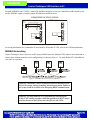
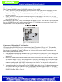
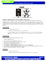
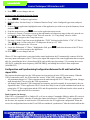
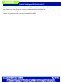
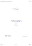
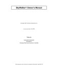
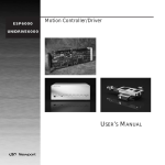
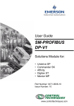
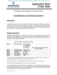
®
technical bulletin
COMPUTER PROCESS CONTROLS
Control Techniques Variable-Speed Drive
(VSD) Interface
Overview
The E2 RX, BX, and CX series of controllers features integration with several models of variable-speed drives
(VSDs) manufactured by Control Techniques, a division of Emerson Industrial Automation. The E2 communicates with the VSD via an RS485 MODBUS network, which allows easier wiring setup and more detailed status
and fault information to be communicated to the E2 than traditional VSDs driven with I/O points.
All E2 control applications that can use VSDs — such as variable-speed condenser fans, AHU fans, and VS
compressors — support selection of Control Techniques drives, making software setup quicker and easier.
Cautions, Warnings, and Notices
WARNING! If an E2 has Commander SK variable speed drives
configured, do NOT remotely upgrade this unit to 2.64F01 and
above if the current version is earlier than 2.64F01. The E2 will
lose communication with Commander SK drives when upgraded.
A technician must be on-site to clean out the Commander SK and
reprogram (follow the instructions in this document to program).
WARNING! Inhibit or disable the VSD before making programming changes. Refer to the VSD’s manufacturer’s instructions
for information on inhibiting the drive.
Compatible Drives and E2 Versions
The E2 controller’s RS485 MODBUS interface communicates with the following Controller Techniques VSD
models:
• Commander SK - Requires E2 version 2.64F01 or above
• Commander SE - Requires E2 version 2.40F01 or above
• Unidrive SP - Requires E2 version 2.40F01 or above
Before Beginning Setup
The networking and configuration instructions in this technical bulletin assume the Control Techniques VSDs are
properly installed, tuned, and programmed by the installer. It is critical that the proper filters, wiring, shielding,
and grounding are done to minimize the EMI generated by these drives. The following is a list of items that must
be addressed to insure proper system operation. Refer to the drive manual on how to do the following:
1. Fitting the correct RFI filter(s) at the power input to the drive,
Document Part # 026-4122 Rev 1 16-JUN-2008
Page 1 of 10
©2008 Emerson Climate Technologies Retail Solutions, Inc. This document may be photocopied for personal use.
Visit our website at http://www.emersonretailsolutions.com/ for the latest technical documentation and updates.
technical bulletin
Control Techniques VSD Interface to E2
2. Mounting the drive against the surface of the RFI filter correctly, removing all paint or non-conducting coatings so that the drive and the RFI filter make good direct electrical contact,
3. Ensuring the filter is connected to the drive using only the wires provided (with no extensions),
4. Using a shielded (screened) or steel wire armored cable to connect the drive to the motor, with the shield connected to the drive gland plate by a good high-frequency connection (using either the conductive cable glands
or the SE11 optional cable screen clamp kit),
5. Grounding the shield of the motor cable to the ground terminal of the motor frame using a link that is as short
as possible and not exceeding 50 mm (2 in) in length (a full 360° termination of the shield to the motor terminal housing, if metal, is beneficial),
6. Ensuring the cables carrying the AC supply and the ground to the filter are at least 100 mm (4 in) from the
drive and motor cable,
7. Avoiding locating noise-sensitive circuits in a zone extending 0.3m (12 inches) all around the drive, and
8. Ensuring the motor cables do NOT run in parallel with control signal cables.
Proper setting of the drive setpoints themselves, outside of what is needed for the VSDs to communicate with
E2s, is beyond the scope of this document. For information about CT drive setpoints and their functions, consult
the Commander SK, Commander SE, or Unidrive SP instructions.
VSD Input Wiring
WARNING! Keep the VSD disabled by leaving
the ENABLE and FWD/RUN signals OPEN until
the drive is ready for use.
If the VSD’s drive speed will be controlled by a 0-10VDC analog output board point from a MultiFlex or 4AO
board controlled by the E2, the point must be connected to the drive’s speed input terminals. Commonly, the
FWD/RUN and ENABLE inputs on the VSD are also be connected to relays on a MultiFlex board so the E2 may
control the run and enable signals.
Figure 1 on page 3 shows wiring for the Commander SK for both 0-10VDC and MODBUS drive control. For
analog control, use Belden 8761 or equivalent cable to connect the analog point to the T1 and T2 terminals on the
Commander SK, and connect a relay point on a MultiFlex or 8RO board to terminals B2 and B5 to control the
FWD/RUN signal.
Document Part # 026-4122 Rev 1 16-JUN-2008
Page 2 of 10
©2008 Emerson Climate Technologies Retail Solutions, Inc. This document may be photocopied for personal use.
Visit our website at http://www.emersonretailsolutions.com/ for the latest technical documentation and updates.
technical bulletin
Control Techniques VSD Interface to E2
For both MODBUS and 0-10VDC, connect B2 and B4 terminals to a relay on a MultiFlex or 8RO board to control the ENABLE signal, or simply jumper B2 and B4 to enable the drive.
COMMANDER SK DRIVE WIRING
0-10VDC Analog Control
ANALOG
POINT
(I/O BOARD)
+
MODBUS Control
T1
BELDEN 8761 OR EQUIVALENT
BLACK
T1
WHITE
T2
SHIELD
SHIELD
T2
T3
T3
T4
T4
B1
B1
B2
DRIVE
ENABLE/
DISABLE
B3
FWD/RUN
B5
B2
DRIVE
ENABLE/
DISABLE
B4
B6
B3
B4
B5
B6
B7
B7
Figure 1 - Commander SK Drive Wiring (Analog and MODBUS)
For wiring information for Commander SE and Unidrive SP models of VSD, refer to the VSD documentation.
MODBUS Networking
Control Techniques drives connect to an E2 using an RS485 network. Multiple VSDs must be interconnected in
a daisy-chain without branches or star configurations, as shown in Figure 2. Use only Belden 8761 shielded twowire cable or equivalent.
Figure 2 - MODBUS Daisy Chain for CT VSD Drives
Warning! Consult the Control Techniques technical manual for your
drive(s) for proper wiring, grounding, and noise prevention. Failure to
do so may result in excessive noise disrupting RS485 communication.
Warning! Use only Belden 8761 or equivalent for networking the
VSDs. CAT5 cabling and other cable that typically uses RJ45 connectors like the one on the VSD are not rated for use with VSDs.
Document Part # 026-4122 Rev 1 16-JUN-2008
Page 3 of 10
©2008 Emerson Climate Technologies Retail Solutions, Inc. This document may be photocopied for personal use.
Visit our website at http://www.emersonretailsolutions.com/ for the latest technical documentation and updates.
technical bulletin
Control Techniques VSD Interface to E2
Connection to E2
The E2 supports MODBUS on any of its RS485 serial ports. These include:
• COM2 - The RS485 serial port onboard the E2 Power Interface Board (PIB). All E2 models have a COM2
port, which is typically used by the CPC I/O Network but may also be designated as a MODBUS port.
• COM4 - The RS485 serial port on the RS485 COM Card (P/N 637-4890), a peripheral board that must be
purchased separately.
• COM6 - The RS485 serial port on the E2 Modem/Expansion COM Card (P/Ns 637-4871, 637-4872, and
637-4873), a peripheral board that must be purchased separately. MODBUS must be connected to the RS485
port as labeled in Figure 3.
The connectors for the COM2, COM4, and COM6 ports are shown in Figure 3. Note that the COM port assigned
for use as MODBUS may not be used to communicate with CPC I/O boards or any other type of serial device only MODBUS devices may be connected to the port.
Figure 3 - E2 PIB COM Port Locations
Connection to VSDs and the CT Drive Interface
CPC requires that all MODBUS network connections to Control Techniques VSDs use a CT Drive Interface
(P/N 535-2725). This assembly, which plugs into the RJ45 MODBUS jack on the VSD, provides the noise filtering circuitry recommended by Control Techniques, and it also provides a screw terminal connector for easier
daisy chaining to the MODBUS network.
1. Using the shielded Ethernet cable included in the CT Drive Interface Kit, connect the CT Drive Interface box
to the RJ45 jack on the VSD. Do not use any other Ethernet cable except the cable supplied in the CT Drive
Interface kit.
2. Connect the MODBUS network cable to the RS485 network connector on the CT Drive Interface. Wire all
485+ terminals on the E2 and CT Drive Interfaces to the same wire color, and wire all 485- terminals to the
other wire color. All bare shield wires should be connected to the 0V terminals. The 0V terminal must also be
connected to earth ground with a 14AWG wire no longer than 6 inches. You may use the earth ground connection on the motor drive. Refer to Figure 4.
3. Terminate the two devices at the endpoints of the MODBUS daisy chain. For the E2, the termination jumpers
will be next to the COM port connector. For the VSDs, use the termination jumpers on the CT Drive Interface. Set the jumpers of the end devices to the TERMINATED positions and all other devices to the UNTERMINATED position. Refer to Figure 4.
Document Part # 026-4122 Rev 1 16-JUN-2008
Page 4 of 10
©2008 Emerson Climate Technologies Retail Solutions, Inc. This document may be photocopied for personal use.
Visit our website at http://www.emersonretailsolutions.com/ for the latest technical documentation and updates.
technical bulletin
Control Techniques VSD Interface to E2
Figure 4 - CT Drive Interface Wiring and Termination Settings
Manually Configuring the VSDs to Enable MODBUS Communication
By default, a Control Techniques VSD is not configured with the right parameter settings to communicate via
MODBUS. Before connecting to an E2, you must use the CT drive’s own keypad interface to change serial networking parameter values. The list below shows the ID number of each parameter that must be changed for each
model type. Refer to the drive manufacturer’s instructions for more information about using the CT drive keypad
interface.
Commander SE:
•
41 - SERIAL MODE: Change to “rtU”
•
42 - BAUD RATE: Recommended value is “19.2” for 19200 baud.
•
43 - SERIAL ADDRESS: Choose a unique MODBUS address number from 1 to 127. The SE drive displays MODBUS addresses with a decimal point (i.e. 10 is displayed as “1.0”, and 2 is displayed as “0.2”). Ignore the decimal
point.
Commander SK:
For the Commander SK, follow the steps below in order:
1.
2.
3.
4.
5.
6.
7.
8.
Inhibit or disable the drive.
Set access to Level 3 (set parameter 10 to “L3”).
Reset the drive to USA defaults (set parameter 29 to “USA”).
Set the Drive Config (parameter 5) to “Pr.”.
Set access to Level 3 (set parameter 10 to “L3”).
Set the SERIAL COMMS BAUD RATE (parameter 43) to “19.2” (19200 baud).
Set the SERIAL COMMS ADDRESS (parameter 44) to a unique MODBUS address number from 1 to 127.
Do not set any other parameters. Exit to save changes.
Unidrive SP:
•
35 - SERIAL MODE: Change to “rtU”
•
36 - SERIAL COMMUNICATION BAUD RATE: Recommended value is “19.2” for 19200 baud.
Document Part # 026-4122 Rev 1 16-JUN-2008
Page 5 of 10
©2008 Emerson Climate Technologies Retail Solutions, Inc. This document may be photocopied for personal use.
Visit our website at http://www.emersonretailsolutions.com/ for the latest technical documentation and updates.
technical bulletin
Control Techniques VSD Interface to E2
•
37 - SERIAL COMMUNICATIONS ADDRESS: Choose a unique MODBUS address number from 1 to 127.
Sharing the MODBUS Network with Other MODBUS Devices
Control Techniques VSDs may share the same network segment as other MODBUS devices communicating with
the E2, provided:
• Each device, regardless of type, has a unique MODBUS address from 1 to 127. In other words, if there are
two VSDs and five Control Link Case Displays (CL-CDs) on the MODBUS network, do not number the
VSDs 1-2 and the Control Link Case Displays 1-5. You must either number the VSDs 1-2 and the CL-CDs 37, or the CL-CDs 1-5 and the VSDs 6-7.
• Each device uses the same baud rate and parity type.
• The number of total devices does not exceed 127.
Adding Control Techniques VSD Drives
Once the Control Techniques VSDs are networked properly, assign the E2 COM port to which the VSDs are connected as a MODBUS port, and specify the number of drives on the network.
1. Log in to the E2 controller with a username/password that has Level 4 (Administrator) access.
2. Press I
(GENERAL CONTROLLER INFORMATION).
3. Port assignments are made in the “Serial” tab of the General Controller Information setup screens. Press
4+ to navigate to the Serial Configuration screen.
4. In the COM Connection field that corresponds to the COM port number to which the VSDs are connected,
press D - LOOK UP and select “MODBUS.”
5. After selecting “MODBUS,” four fields will appear below the COM Connection field. These fields define
the format of the messages coming from the VSDs and must be set to the following values:
• Baud Rate - To match the baud rate settings specified in the VSDs, set the baud rate to 19200.
• Data Size - 8
• Parity - None
• Stop Bits - All CT VSD drives use 2 stop bits, but since all other MODBUS-enabled Emerson Climate Technologies devices use 1 stop bit, the E2 has been programmed to automatically use 2 stop bits in messaging to
CT VSD devices only. Therefore it is recommended you leave the Stop Bits field set to 1.
6. When you have finished entering the MODBUS settings, press J to save changes and return to the System Information menu.
7. Press I
(CONNECTED I/O BOARDS AND CONTROLLERS).
8. In the Connected I/O screen, locate the field in the ECT Devices box labeled “CT Drive.” Enter the total
number of VSDs on the network in this field.
9. Press J to save changes and return to the Network Setup menu.
Commissioning the VSD
Once you have set the COM port for MODBUS and added a number of CT drives, the next step in VSD setup is
to edit the application parameters in the E2 to set drive type, address, and control type:
1. Press I - Configured Applications
2. Use the arrow keys to highlight “CT Drive” in the Configured Apps menu. Press >.
Document Part # 026-4122 Rev 1 16-JUN-2008
Page 6 of 10
©2008 Emerson Climate Technologies Retail Solutions, Inc. This document may be photocopied for personal use.
Visit our website at http://www.emersonretailsolutions.com/ for the latest technical documentation and updates.
technical bulletin
Control Techniques VSD Interface to E2
3. If multiple CT drives are set up, highlight the name of the drive you wish to set up and press >.
4. The CT Drive Status screen should be visible. From this screen, press E to access the CT Drive setup
screens. The first setup screen shown will be “General.”
Screen 1: General
Figure 5 - CT Screen 1: General
5.
6.
7.
8.
Enter a name for the VSD in the “Name” field.
Enter the MODBUS address for this drive in the “Physical Addr” field.
Choose the VSD model type (Commander SK, Commander SE, or Unidrive SP) in the Drive Type field.
In the Control Method field, select “0-10V Reference” if controlling drive speed from an analog point, or
“MODBUS Network” if the E2 will control drive speed directly through the MODBUS interface.
9. Press J to save these changes and exit.
10. Remain on the CT Drive Status screen. You should see live values appearing in the “Current Conditions” status fields (such as Hz/RPM) as the E2 makes connections between the CT Drive application inputs and outputs and the VSD’s inputs and outputs. Remain on this status screen until the Setpt Status field shows either
“In Sync” or “Sync/Error.” (Note: the screen may show Sync/Error even when no error is occurring - this is
normal. Ignore this parameter until the drive is fully configured. See “Configuration and Synchronizing Configuration Between the E2 and Control Techniques VSDs” on page 9.)
Document Part # 026-4122 Rev 1 16-JUN-2008
Page 7 of 10
©2008 Emerson Climate Technologies Retail Solutions, Inc. This document may be photocopied for personal use.
Visit our website at http://www.emersonretailsolutions.com/ for the latest technical documentation and updates.
technical bulletin
Control Techniques VSD Interface to E2
11. When the Setpt Status field shows “In Sync” or “Sync/Error,” press E to return to the CT Drive setup
screens. Complete the drive programming by setting the necessary setpoints in the Setpoints, Alarms, and
Advanced tabs.
Figure 6 - CT Drive Setpoints Tab
When finished programming, press J to save changes and exit. On the CT Drive status screen, you should
see the Setpt Status field change to the value “In Sync.” The final step in CT Drive setup is to associate the VSD
with the application that will be commanding it.
VSD Association With E2 Control Applications
Most E2 control applications that can use variable-speed drives may be associated with Control Techniques
VSDs. They are:
• Suction Group and Enhanced Suction Group (for controlling variable-speed compressors)
• Condenser (for controlling variable-speed fans)
• AHU (for controlling variable-speed blowers)
To associate an application with a CT VSD, navigate to the application’s setup screens, locate the field that determines device type or fan type, and set that field to “CT Drive.”
Condenser & AHU
1. Press I - Configured Applications.
2. Highlight either “Condenser” or “AHU” in the Configured Apps menu, and press >.
3. If more than one application, highlight the name of the application you wish to set up in the Summary Screen
and press >.
4. From the status screen, press E to access the application setup screens.
5. Locate the “Fan Type” field on screen C1: General. Highlight this field, press D, and select “CT Drive”
as the fan type.
6. Navigate to the screen where the advanced VS setup parameters are (screen C4: VS Setup for Condensers,
screen C8: Adv Fan for AHU).
7. Locate the field named “CT Drive.” Highlight this field, press D, and select the name of the CT Drive
application you wish to assign to this application.
Document Part # 026-4122 Rev 1 16-JUN-2008
Page 8 of 10
©2008 Emerson Climate Technologies Retail Solutions, Inc. This document may be photocopied for personal use.
Visit our website at http://www.emersonretailsolutions.com/ for the latest technical documentation and updates.
technical bulletin
Control Techniques VSD Interface to E2
8. Press J to save changes and exit.
Suction Group & Enhanced Suction Group
1. Press I - Configured Applications.
2. Highlight either “Suction Group” or “Enhanced Suction Group” in the Configured Apps menu, and press
>.
3. If more than one application, highlight the name of the application you wish to set up in the Summary Screen
and press >.
4. From the status screen, press E to access the application setup screens.
5. In Screen 1: General, if you have not set up the total number of compressor stages in the rack, enter the correct number in the “Num of Stages” field. This will cause the “C6: Comp Setup” tab to be visible.
6. Press 4+ to navigate to the Comp Outs screen.
7. For stage #1 in the Comp Outs screen, highlight the “TYPE” field and set this field to “CTdr” (CT Drive).
This assigns stage 1 of the rack to be a VS compressor driven by a CT VSD.
8. Press 4+ to navigate to the VS screen.
9. Locate the field named “CT Drive.” Highlight this field, press D, and select the name of the CT Drive
application you wish to assign to this application.
10. Press J to save changes and exit.
When a CT Drive application is associated with a control application, the E2 automatically connects all of the
necessary inputs and outputs of the CT Drive to the inputs and outputs of the control application that are responsible for: controlling the drive’s forward/run (RUN) and variable speed percentage (VS); resetting the inverter
(INV RST); reading the motor frequency (MOTOR FREQ); and reading the inverter’s alarm output state
(ALARM OUT).
Configuration and Synchronizing Configuration Between the E2 and Control Techniques VSDs
The setpoints that determine how the VSD operates are kept and saved in the VSD’s own memory. When the
VSD is connected to an E2, the E2 becomes the “master” of the VSD’s setpoints. This means:
• All permanent changes to CT Drive setpoints must be made through the E2’s CT Drive application. Changes
made through the E2 are saved to the VSD as permanent.
• All changes made from the VSD’s front panel are temporary and will eventually be overwritten by the configuration in the CT Drive application. The E2 checks once daily for out-of-synch conditions between the setpoints in the CT Drive application and the VSD, and all setpoints that are different from the values stored in
the CT Drive application will be overwritten.
Read Setpoints On Startup
If the VSD is a Commander SE or Unidrive SP, or if you are using a Commander SK drive and the E2 version is
before version E2 2.64F01, when the E2 makes the connection between a VSD and a CT Drive application for
the first time, the setpoints are read from the VSD and saved to the E2’s application configuration. When this
occurs, the configurations between the E2 and VSD are considered “synchronized.”After the initial read from the
Document Part # 026-4122 Rev 1 16-JUN-2008
Page 9 of 10
©2008 Emerson Climate Technologies Retail Solutions, Inc. This document may be photocopied for personal use.
Visit our website at http://www.emersonretailsolutions.com/ for the latest technical documentation and updates.
technical bulletin
Control Techniques VSD Interface to E2
VSD occurs, as long as the VSD is associated with a CT Drive application in the E2, the E2 will be considered
the primary device when keeping the setpoints synchronized between the E2 and VSD.
When using a Commander SK drive with E2 version 2.64F01 or above, E2 will not read setpoints when first connected. Drive parameters will need to be programmed from the E2.
Document Part # 026-4122 Rev 1 16-JUN-2008
Page 10 of 10
©2008 Emerson Climate Technologies Retail Solutions, Inc. This document may be photocopied for personal use.
Visit our website at http://www.emersonretailsolutions.com/ for the latest technical documentation and updates.