1
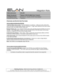
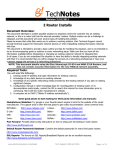
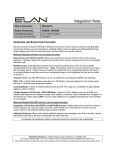
ELAN Home Systems
Life Just Got Better
TS2 Integration Note
Manufacturer:
ELAN Home Systems
Model Number(s):
TS2, (OleXL updated to TS2)
Software Versions:
Document Revision Date:
Automation Controller - 5.0 build 637 or later
ELAN SC1 - 1.0.3.1
ELAN TS2 - 1.0.4.1 or newer
ELAN OleXL – must be flashed as TS2, see procedure below.
g!ConnectPro version 5.2 build 583 or later
03/28/2013
OVERVIEW AND SUPPORTED FEATURES
The TS2 keypads communicate on a dedicated VIA!Net bus to provide a compact single zone two way
user interface. The legacy system controllers (HomeBricks and MultiBricks) will require an ELAN SC1
serial controller (RS-232 x VIA!Net) to communicate with the keypads. The HC series controllers will
have a VIA!Net jack built in and will not require the SC1. Up to 32 keypads can be connected on a single
VIA!Net bus. Refer to the TS2 installation manual for detailed installation diagrams and power
requirements.
Note: The SC1 must be connected to a serial port on the controller. It is NOT compatible with
SerialBricks, Global Cache ports, or Moxa ports. The SC1 must also be using the above firmware
version. Newer firmware versions may not work.
IMPORTANT: THIS LEGACY FEATURES IS ONLY SUPPORTED IN 5.0 SYSTEMS.
ELAN HC CONTROLLERS DO NOT SUPPORT OR REQUIRE SC1.
THE TS2 KEYPAD SUPPORTS THE FOLLOWING FEATURES:
System Mode Control: The home interface may be optionally configured to provide system mode status
and control.
Basic Time & Weather information: The home interface may be optionally configured to display time
and basic weather information.
Lighting Control: The lighting interface displays a custom lighting keypad for 2-way control of scenes or
lighting loads.
Security Control: The security interface displays status of one partition and a keypad to arm/disarm it.
Climate Control: The climate interface displays status of one climate zone and provides mode, fan, and
set point adjustments.
Media Control: The media interface displays status of one media zone and provides controls for power,
source, volume, mute, and basic source control. The interface provides meta data feedback (no cover art
at this time) for supported two way devices or customizable single or multi-page interfaces for one way
device control. See limitations below.
ELAN Home Systems | Lexington, KY USA | Technical Support: 800-622-3526
THE TS2 KEYPAD DOES NOT SUPPORT THE FOLLOWING FEATURES:
Various custom controls: Not all custom controls are supported on the TS2 interface. The result of this
may be limited source control of various 3rd party AV sources.
2 of 11
INSTALLATION OVERVIEW
1. During the rough-in phase install the necessary power and cabling for the TS2 keypads. See
connection diagrams below and refer to ELAN documentation for keypad power requirements.
2. If using the TS2 keypads with Legacy controllers (HomeBricks or MultiBricks) you will also need to
run a Cat5 wire from the location of the VIA!Net port on the Controller or SC1 back to the Network
Assembly of the OneHome system to provide the serial connection needed to communicate. Refer to
the RS-232 Connection Options Integration Note for other serial connection options.
3. Install the keypads and other home media and control components.
4. Connect the OneHome system to the VIA!Net electrically. See the connection diagram for more
information.
5. Configure the OneHome system for the keypads and confirm communication between the keypads
and the controller.
6. Configure and test the keypads for proper operation, See HomeLogic configuration details below.
INITIAL SC1 CONFIGURATION NOTES
NOTE: The ELAN SC1 Serial Controller device is used to provide an RS-232 to VIA!Net bridge and is
required when using TS2 keypads with Legacy HomeBrick and MultiBrick controllers.
The SC1 must be updated using the following procedure for use in a g! system. If you are unsure
of the version of the SC1 use the following procedure to update it to the minimum version. This
procedure requires a PC with a USB port, a USB “A” to USB “Mini-B” cable, the SC1, the ELAN Firmware
Update Utility included with g!ConnectPro, and the ELAN Common Resources Library available from the
ELAN dealer website which includes the required firmware files.
SC1 Firmware update procedure:
1. Verify that you have g!ConnectPro version 5.2 Build 583 or newer.
2. Run the Firmware Updater: Click Start/All Programs/ELAN Home Systems/ Tools/Firmware Updater.
3. Using the USB-USB-mini cable connect the SC1 to the PC. Remove all other connections to the
SC1, it will be powered by the USB connection during the update.
Note: if this is the first time an ELAN USB device is connected to your PC you may see a pop-up
message as the USB device driver installation is completed which may require a reboot of your
system.
4. From the Device drop down menu select SC1. The firmware files window will populate with the
available firmware files.
5. Click the Transfer button. The Status window will indicate the progress as the firmware is
downloaded to the device.
6. Wait for the download to complete then click done to close the update utility. Disconnect the SC1
from the PC.
3 of 11
OLEXL – TS2 UPDATE PROCEDURE
NOTE: Use the following procedure to convert an OleXL for use as a TS2, this update is not required for
TS2 keypads. This procedure requires a PC with a USB port, a USB “A” to USB “Mini-B” cable, the
ELAN Firmware Update utility included with g!Connect Pro, the ELAN Common Resources Library, and
the OleXL.
OleXL-TS2 Firmware update procedure:
1. Verify that you have g!ConnectPro version 5.2 Build 583 or newer
2. Run the Firmware Updater: Click Start/All Programs/ELAN Home Systems/ Tools/Firmware Updater.
3. Using the USB-USB-mini cable connect the TS2 to the PC. Remove all other connections to the
TS2, it will be powered by the USB connection during the update.
Note: if this is the first time an ELAN USB device is connected to your PC you may see a pop-up
message as the USB device driver installation is completed which may require a reboot of your
system.
4. From the Device drop down menu select TS2. The firmware files window will populate with the
available firmware files.
5. Click the Transfer button. The Status window will indicate the progress as the firmware is
downloaded to the device.
6. Wait for the download to complete then click done to close the update utility. Disconnect the TS2
from the PC.
7. Replace the OleXL film with the TS2 film, see the TS2 Installation manuals for detailed instructions.
8. Set the Z-NET/VIA!Net switch on the back of the unit to the VIA!NET position.
4 of 11
INITIAL KEYPAD CONFIGURATION NOTES
The TS2 keypads are automatically added to the system using the configurator and can not be added
manually. Use the following procedure to make initial keypad connections to the system.
1. Connect and power up all keypads per the connections diagram below. The keypads should boot to
a screen with an option to GET ADDRESS. If the keypad does not boot to the GET ADDRESS
screen then follow the steps below:
a. Press the service menu button (located behind bezel and below Mini-USB connection and
light sensor) once to access the MAIN MENU screen.
b. Press the UP/DOWN buttons to highlight VNet addr then press the Enter button.
c.
Press the UP/DOWN buttons to highlight Reset addr then press Enter.
2. In the configurator, click on the interface tab and add the SC1 as a communication device then select
the COM port that it is connected to. See HomeLogic Configuration Details below.
3. On the TS2 (OleXL) keypad, verify the GET ADDRESS menu item is highlighted and press the Enter
button. The keypad will receive an address from the controller and display it at the top of the screen.
Note: If more than one keypad is to be installed it may be helpful to make note of the address and the
physical location of the keypad to aid in selecting the proper control zones in the following steps.
4. On the TS2 (OleXL) keypad, with the OK menu item highlighted press Enter. The controller will
check the keypad program and download any required information to it. Be patient this may take up
to 5 minutes.
5. Repeat steps 1-4 until all keypads have been added.
6. Using the address noted in step 3 identify each keypad on the Interface Tab and configure the
desired zones, partitions, control, and backlight behavior. See HomeLogic Configuration Details
below.
5 of 11
CONNECTION DIAGRAMS (VIA SC1 & SPP PRECISION PANEL)
VIA!NET
EXT IR
TO SENSE INPUTS
1
2
SS/SC4
3
USE STEREO 3.5mm PLUGS ONLY
4
5
6
1
2
3
4
5
6
7
8
ZONE
ZONE
1
5
TRIGGERS
ZONE
2
TS2 Touchpad
ZONE
POWER
ZONE
+
3
TS2 Touchpad
6
ZONE
--
7
1
ZONE
ZONE
16VDC / 10A
4
8
16VDC / 4A
1
Cat5 Cable Assembly
(Standard Ethernet)
16VDC/1.5A
2
®
COM 1,2,3,4
16V/1.5A
POWER
SUPPLY
Network Assembly
DB9 x RJ45 NULL Adapter
16V/1.5A
Power Supply
1
Cat5 Cable Assembly
(ELAN VIA!NET)
4
IN
OUT
12VDC
ELAN
SC1
RS-232
Control
System Controller
2
Cat5 Cable Assembly
(Standard Ethernet)
1 – ELAN Standard Cat5 Cable
2 – Ethernet Standard Cat5 Cable
3
3 – SC1 DB9M to RJ45 Adapter
4 – HA-CB-328 DB9F to RJ45 NULL Adapter
REAR PANEL CONNECTIONS AND SWITCHES
485+
G
16V
G
16V
C
N/C
IR
485485+
G
V INT
G
V
EXT
N/C
IR
Z7C 12V OLÉ/ZPAD
485-
Z7B 16V/12V VIA!/OLÉ
B
N/C
IR
485485+
G
12V
G
N/C
TS2 Touchpad
(Zone 7)
B
TS2 Touchpad
(Zone 8)
6 of 11
C
N/C
IR
485485+
G INT
V
G
V
EXT
Z8C 12V OLÉ/ZPAD
White/Blue
Orange
White/Orange
Green
White/Green
Brown
White/Brown
Z8B 16V/12V VIA!/OLÉ
NOTE: When using the “B” punch-downs it is
necessary to flip the “INT/EXT” switch to the
EXT position to provide power to the TS2. (The
“A” 110 punch-down block has been removed from
the picture for clarity.)
A
White/Blue
Orange
White/Orange
Green
White/Green
Brown
White/Brown
Z7A 16V VIA!/OLÉ
Punch-downs
The SPP Precision Panel has eight “zone” punchdown locations on the reverse side. Each location
has “A,” “B,” and “C” 110 punch-downs. For the
purpose of integrating TS2s the “C” 110 punchdowns are NOT used. A MAXIMUM of 16 TS2s
can be connected to one SPP by using the “A” and
“B” punch-downs in each zone location. “Doublepunching” multiple wire runs to one 110 block is
NOT recommended.
N/C
IR
485485+
G
12V
G
N/C
REAR PANEL CONNECTIONS AND SWITCHES (CONTINUED)
Linking SPPs
Multiple SPPs may be linked together using the “LINK” connections on the
reverse side. This link carries V-Net information only. This connection uses
the ELAN standard color code.
ZNET/VNET Switch
When integrating TS2s with a ZNET based system (S128P) this switch
must be in the up (ZNET) position. When used with a VNET based
system (S86A/P) this switch must be in the down (VNET) position.
LINK IN
LINK OUT
S6/S128P
(ZNET)
S86A/P
(VNET)
SS/SC4 Switch
This switch MUST be set to the up (SS/SC4) position.
SS/SC4
NO SS/SC4
FRONT PANEL CONNECTIONS
When using an SPP it is necessary to connect a 16VDC power supply to the front of the panel. This will
provide power for the TS2s and the SC1.
You can connect up to nine TS2s using the 1.5 amp 16VDC power supply. If adding more than nine TS2s
the 4 amp 16VDC power supply is required. A MAXIMUM of 23 TS2s (plus the SC1) can be powered by
one 4 amp power supply.
When using multiple SPPs it is recommended to power each SPP panel with a dedicated power supply.
7 of 11
FRONT PANEL CONNECTIONS (CONTINUED)
SC1 Connections
The SC1 connects to the front of the SPP at the RJ-45 connection labeled “VIA!NET”
using a cat5 jumper pinned out to the ELAN standard color code. You can connect up
to two SPPs directly to the SC1 by using the “IN” connection to one SPP and the
“OUT” connection to the other SPP.
VIA!NET
IR Connections
If you are not using the IR receivers built into the TS2s it is NOT necessary to connect cat5 jumpers from
the front of the SPP to the A/V Controller (S12P, S86A/P, etc.) keypad inputs. If you will be using the IR
receivers then cat5 jumpers will be needed.
Be sure to connect the Zone One connection from the SPP to the Zone One keypad input on the
A/V Controller, Zone Two’s connection from the SPP to Zone Two’s keypad input of the A/V
Controller and so on to maintain proper IR routing.
The cat5 jumpers from the SPP to the keypad inputs should follow the ELAN standard color code.
WIRING STANDARD – ELAN CAT5 STANDARD CODE
The color code for the TS2 wiring follows the ELAN standard code as follows.
ELAN Standard
Insert wires in this order:
Blue
White/Blue
Orange
White/Orange
Green
White/Green
Brown
White/Brown
PR1 PR2 PR3 PR4
BL OR GR BR
1 2 3 4 5 6 7 8
8 of 11
CONNECTION DIAGRAMS (VIA SC1 & PPVN PRECISION PANEL)
Cat5 Cable Assembly
(Standard Ethernet)
1
6
9
PPVN
2
COM 1,2,3,4
TS2 Keypad
DB9 x RJ45 NULL Adapter
Network Assembly
4
8
Cat5 Cable Assembly
(ELAN VIA!NET)
See pinout below
IN
OUT
12VDC
ELAN
SC1
RS-232
Control
3
5
6
Cat5 Cable Assembly
(Standard Ethernet)
7
10
System Controller
Notes:
1. Standard serial connection method shown above. Alternatively a single Cat5 can be terminated per the
optional pin-out diagram below to connect directly between a COM port and the SC1.
2. Up to 4 TS2 keypads can be connected to each PPVN panel for power and VIA!NET communication.
3. Up to 8 PPVN panels can be daisy chained on a single SC1 converter for a total of 32 TS2 keypads
maximum on the VIA!NET bus. Each PPVN will require its own power supply, item #3 above.
BILL OF MATERIALS
#
1
2
3
4
5
6
7
8
9
10
Device
TS2 Keypad
PPVN Precision Panel
16VDC x 1.5A Power Supply
Cat5 Cable Assy. (ELAN)
Serial Controller
Cat5 Cable Assy. (Ethernet)
DB9M to RJ45 Adapter
DB9M to RJ45 NULL Adapter
Network Assembly
HomeBrick
Manufacturer
ELAN
ELAN
ELAN
Installer
ELAN
Installer
ELAN
ELAN
ELAN
ELAN
Part Number
TS2
PPVN
PWR1
N/A
SC1
N/A
SC1 Adapter
HA-CB-328
HW-NA-18X4
HW-HB-1080
Protocol
VIA!NET
VIA!NET
N/A
VIA!NET
VIA!NET x RS-232
RS-232
RS-232
RS-232
RS-232
RS-232
Connector Type
RJ-45F
RJ-45F x Punch Down
Plug
RJ-45 Male X RJ-45 Male
RJ-45F x RJ45F
RJ-45 Male X RJ-45 Male
DB-9 Male X RJ-45 Female
DB-9 Female X RJ-45 Female
RJ-45 Female X DB-9 Female / USB
DB9 Male / USB
Notes
Use 1 for SC1 & 1 for each PPVN
Use ELAN Color Code
Must terminate all 8 conductors
Alternatively use HA-CB-307
CABLE PIN-OUTS
Optional Single Cat5 Serial Cable Method
COM port to SC1
RJ45
Position
RJ45
White/Orange
1
White/Orange
Orange
2
No Connection
White/Green
3
No Connection
Blue
4
Blue
White/Blue
5
Green
Green
6
White/Blue
White/Brown
7
Brown
Brown
8
White/Brown
ELAN VIA!NET Cable
Blue
1
Blue
White/Blue
2
White/Blue
Orange
3
Orange
White/Orange
4
White/Orange
Green
5
Green
White/Green
6
White/Green
Brown
7
Brown
White/Brown
8
White/Brown
9 of 11
HOMELOGIC CONFIGURATION DETAILS
The following table provides settings used in the HomeLogic Configurator. Please refer to the Configurator Reference Guide for more details.
o
“<Select>”
Select the appropriate item from the list (or drop-down) in the Configurator.
o
“<User Defined>”, etc.
Type in the desired name for the item.
o
“<Auto>”
This field will automatically populate during configuration
Devices
Communication Devices
Variable Name
Name
Type
Communication Type
Location
COM Port
Interface Devices<Auto Discover> Name
Device Type
COM Device
VIA!NET ID
Enable Weather Page
Enable Forecast Page
Enable Sys Mode Page
Media Zone
Security Partition
Lighting Keypad
Thermostat
Backlight Timeout
Setting
Comments
<User Defined> (Example: ELAN SC1)
Serial Port
ViaNet SC1
<User Defined> (Not Required)
<Select>
<User Defined> (Default: TS2 ViaNet XX)
ELAN TS2
<Auto> (Default: ELAN SC)
<Auto>
<Select>
<Select>
<Select>
<Select>
<Select>
<Select>
<Select>
<Select>
Notes:
1. The TS2 keypads are automatically discovered, refer to Inititial Keypad Configuration Notes above
2. If not already chosen, select the COM device that refers the TS2 to the proper SC1 and COM port.
3. The TS2 keypad IDs will be addressed automatically as they are imported into the system.
4. Select <Yes> to enable the optional page
5. Select the desired zone, partition, or behavior for each keypad
10 of 11
See Note#1
See Note #2
See Note #3
See Note #4
See Note #4
See Note #4
See Note #5
See Note #5
See Note #5
See Note #5
See Note #5
COMMON MISTAKES:
1. Not using a null-modem connection between the controller and the SC1.
2. Not updating the SC1 or OleXL with the ELAN Firmware Updater. The SC1 needs to be running
1.0.2.3 or newer, see update procedure above. OleXL keypads need to be updated to be
compatible with the g! software.
3. Not setting the switch on the back side of an OleXL properly. OleXL Keypads have a switch to
select the communication type, setting the switch to VIA!Net will allow communication between
the keypad and controller.
4. Not waiting for all transfers to the TS2 to complete. Initial transfer to newly installed TS2 keypads
can take up to 5 minutes per TS2, e.g., eight TS2 keypads ~ 40 minutes (thereafter, most
transfers should occur very quickly). TS2 keypads will appear non-functional while VIANet is
busy transferring initial data or future firmware updates but can be used normally when transfers
are complete.
5. Cross-connecting with a legacy VIANet bus or User Interface. When replacing a legacy ELAN
system with VIANet user interfaces with a g! system and TS2 keypads, either the VIANet bus
used for SC1 and TS2 must be independent of the existing VIANet or all existing legacy VIANet
user interfaces (VIA! Panels, Ole, OleXL) must be removed from the VIANet bus. Otherwise it is
very likely that VIANet Unit ID (address) conflicts will prevent the TS2 keypads from working
correctly.
11 of 11