1
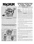
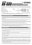
RX-472 w/Sanwa Synchronized Link
2.4GHz FH4T Super Response Receiver User's Guide
The RX-472 2.4GHz FH4T Super Response 4-channel receiver with Sanwa Synchronized Link (SSL) features an extremely low latency time and
high frame rate, which makes you feel more connected to your model than ever. Combined with Airtronics or Sanwa Super Response SRG digital
servos, the RX-472 will give you reaction speeds like never experienced before! This new receiver, when used with an Airtronics M12 or Sanwa
EXZES-Z transmitter and the Sanwa Super Vortex ZERO ESC or other SSL compatible ESC, allows you to change many ESC programming mode
options directly from the transmitter using the transmitter's CODE AUX function. This saves you the time and hassle of not needing to stop and make
adjustments manually through the ESC. You can make these adjustments on the fly. In addition, telemetry data such as speed or RPM, ESC temperature,
motor temperature (if supported), and battery voltage can be read directly from the Super Vortex ZERO ESC and displayed on the transmitter.
IMPORTANT: This receiver is not compatible with Airtronics or Sanwa FH2 surface transmitters or aircraft transmitters. SSL function only available
when used with an M12 or EXZES-Z transmitter and Super Vortex ZERO ESC or other SSL compatible ESC. Super Response (SSR) feature only
available when used with an Airtronics or Sanwa FH4T transmitter in SSR Mode with Airtronics or Sanwa Super Response SRG digital servos.
Telemetry requires telemetry capable transmitter (M12, EXZES-Z, MT-4) AND Super Vortex ZERO ESC or other SSL compatible ESC. If not using
the Super Vortex ZERO ESC, the RX-472 can send telemetry data for the voltage of the receiver battery pack only.
2.4GHz frequency band precautions
• This receiver operates on the 2.4GHz frequency band. The 2.4GHz connection is determined by the transmitter and receiver pair. Unlike
ordinary crystal-based systems, your model can be used without frequency control.
• Due to differences in the implementation of 2.4GHz technology among different manufacturers, this receiver is not compatible with any other
transmitter brands.
• The 2.4GHz frequency band may be used by other devices, or other devices in the immediate area may cause interference on the same
frequency band. Always before use, conduct a bench test to ensure that the servos operate properly. Also, conduct checks with the transmitter
as distant as possible from your model.
• The response speed of the receiver can be affected if used where multiple 2.4GHz transmitters are being used, therefore, carefully check the
area before use. Also, if response seems slow during use, stop your model immediately and discontinue use.
• If the 2.4GHz frequency band is saturated (too many transmitters on at once), as a safety precaution, the transmitter and receiver may not bind.
This ensures that your radio control system does not get hit by interference. Once the frequencies have been cleared, or the saturation level
has dropped, your transmitter and receiver should be able to bind without any problems.
Receiver precautions
• If you're using analog servos, DO NOT use SHR or SSR Servo Modes for that channel, otherwise the servos and/or receiver can be damaged.
• Do not plug any device other that an SSL compatible device or a switch harness w/receiver battery into the BATT/SSL port.
• The antenna consists of a coaxial cable and a reception wire (the thin tip at the end of the coaxial cable). When you
mount the antenna, do not bend the reception wire. Reception performance decreases if the reception wire is bent. The
coaxial cable can be bent into gentle curves, however, do not bend the coaxial cable acutely, or repeatedly bend it, or
the antenna core can be damaged.
Antenna
Reception Wire
Coaxial Cable
Antenna Tube
• The antenna should be installed into a vertical plastic tube per your particular model's assembly instructions. See diagram.
Keep the antenna as far away from the motor, battery and ESC as possible. The antenna should not come into contact
with any carbon or metal chassis components.
• The receiver is susceptible to vibration, shock and moisture. Take appropriate measures to protect against vibration and
moisture. We suggest wrapping the receiver in shock-absorbing foam when installing it into your model.
• The antenna is delicate, therefore, handle it with care. Do not pull on the antenna with force. Do not cut the coaxial cable or the antenna reception
wire. Do not alter the length of either the coaxial cable or the antenna reception wire.
• There is a danger of runaway operation if connectors loosen during use. Make sure that all connectors are securely fitted.
Receiver specifications, led condition indicator and connections
IMPORTANT: The receiver's Nominal Input Voltage is 3.7 to 7.4 volts. A 2 cell LiPo or LiFe battery pack can be used to power the receiver
without the use of a voltage regulator. In addition, this allows you to take advantage of the higher torque and speed provided by using 7.4 volt
servos. Only use a 2 cell LiPo or LiFe battery pack if your servos are rated to handle the higher voltage!
• We suggest binding the transmitter and receiver and making all receiver connections to check for correct operation prior to mounting the
receiver in your model. See the Binding the Transmitter and Receiver section on the reverse side.
• After binding the transmitter and receiver, choose the desired Servo Mode and program the Fail Safe function.
Bind LED
Specifications:
• Frequency: 2.4GHz FH3/FH4T Selectable Via Transmitter
• Nominal Input Voltage: 3.7 to 7.4 Volts
BATT/SSL*
CH 4 - Auxiliary 2
CH 3 - Auxiliary 1
CH 2 - ESC
CH 1 - Steering
• Weight: 0.23oz (6.6g)
• Dimensions: 1.18 x 0.91 x 0.55in (30.0 x 23.3 x 14.0mm)
• Battery Fail Safe Limit: 3.5 to 5.0 Volts (FH3) / 3.5 to 7.4 Volts (FH4T)
Coaxial Cable
Bind LED Condition Indicator:
= Signal
= Positive
= Negative
The Bind LED on the receiver can be used to determine receiver condition at a glance. The
Bind LED will alert you to various receiver conditions, as described below:
Condition
LED
Blue
Receiving RF Signal
Blue Flash Slow/Blue Flash Fast
Binding Operation
Red & Blue Flashing
Receiver Battery Fail Safe Activates
Red
No RF Signal After Receiver Battery Fail Safe Activates
Bind Button
Antenna Reception Wire
*If using the Sanwa Super Vortex ZERO or other
SSL compatible ESC, plug the ESC into the
BATT/SSL slot, otherwise SSL features and
telemetry data will not be available. All other
ESC's should be plugged into the CH 2 - ESC slot.
binding the transmitter and receiver
The binding procedure allows you to bind the transmitter and receiver pair. Once the binding procedure is complete, the setting is remembered
even when the transmitter and receiver are turned OFF. The bind code is unique to each transmitter and receiver pair, so you don't need to worry
about other users' transmitters interfering with your receiver.
IMPORTANT: Before beginning the binding procedure, make all receiver connections as described on the reverse side. If there is a problem
binding the transmitter and receiver with the ESC connected, disconnect the ESC and use a separate battery pack to power the receiver. After
completing the binding procedure, disconnect the battery pack and reconnect your ESC.
1) Turn the transmitter ON and navigate to the BIND menu, then choose your transmitter's modulation type. If using an M12, EXZES-Z, MT-4
or other FH4T transmitter, choose FH4T. If using an M11X, MX-3X or other FH3 transmitter, choose FH3.
2) While holding down the Bind Button on the receiver, turn the receiver ON. The Bind LED on
the receiver will flash slowly. After approximately 2 seconds, release the Bind Button. The Bind
LED on the receiver will continue to flash slowly.
3) From within the transmitter's BIND menu, press the ENTER key on your transmitter. The [ENTER] command will begin to flash and the Bind
LED on the receiver will flash rapidly, then go out.
4) After the Bind LED on the receiver goes out, press the ENTER key a second time. The Bind LED on the receiver will illuminate solid blue,
indicating that the binding procedure is complete.
5) Move the steering wheel and throttle trigger to verify that the servos are operating normally, then press and HOLD the Back/Cancel key to
exit the BIND menu.
IMPORTANT: The BIND menu may vary depending on your transmitter model. If necessary, refer to your transmitter's User's Guide for more
information about binding the transmitter and receiver. When the binding procedure is successful, the Bind LED on the receiver will illuminate
solid blue. If the Bind LED on the receiver is flashing rapidly or is not illuminated at all, the transmitter and receiver are not paired. In this case,
turn both the transmitter and receiver OFF, then repeat the binding procedure again.
servo mode setting
The Servo Mode setting is used to change the response time of the receiver to suit the type of servos you're using. The combination of using digital
servos and using the correct Servo Mode setting results in increased reaction speed and improved feel, making you feel more connected to your
model than ever. For example, using the SHR Servo Mode setting with any brand of digital servo will increase the servo's response time, even
above the manufacturer's specification. For the fastest response time possible, use the SSR Servo Mode setting with Airtronics or Sanwa Super
Response SRG digital servos.
For more information about the Servo Mode setting and how to program it, refer to your transmitter's User's Guide. The following Servo Modes can
be programmed from your transmitter's Modulation Menu:
NOR - Use with any brand of Analog or Digital servos and ESCs.
SHR - Use with any brand of Digital servos only. Do not use with Analog servos!
SSR - Use with Airtronics or Sanwa SRG Digital servos only. Do not use with Analog servos or any other type or brand of Digital servos!
WARNING: If you're using analog servos, DO NOT use SHR or SSR Servo Modes for that channel. Use the NOR Servo Mode with analog servos.
Using SHR or SSR Servo Modes with analog servos can result in damage to the servos or the receiver!
Not all ESCs are compatible with SHR or SSR Servo Modes. If your ESC does not operate correctly with SHR or SSR Servo Modes, change the
Throttle Channel Servo Mode to NOR.
The SSR Servo Mode is available only when using FH4T modulation. In addition, Servo Mode options may differ depending on the transmitter
model used. When switching between SHR and SSR Servo Modes, your model's End Point Adjustment (EPA) settings may be altered. In this
case, you should double-check the EPA settings and readjust them if necessary.
fail safe function
The Fail Safe function can automatically move the servos to a predetermined position in the event that the signal between the transmitter and the
receiver is interrupted, whether due to signal degradation or low transmitter battery. The Fail Safe function can be programmed independently on
all four channels and three options are available: FREE, HOLD and PERCENTAGE. For information about programming the Fail Safe function, refer
to your transmitter's User's Guide.
IMPORTANT: The Fail Safe function will NOT OPERATE if the receiver loses power. It will operate only if the transmitter and receiver signal is
interrupted or if the transmitter loses power. A Receiver Battery Voltage Fail Safe function is also featured, however, it is used with glow- or gaspowered models. It's not necessary to program this feature when used with an ESC.
warranty and service information
Your Airtronics RX-472 receiver is warranted against manufacturer defects in materials and workmanship, at the original date of purchase. This
warranty does not cover suitability for specific application, components worn by use or improper voltage, tampering, modification, misuse, abuse,
improper wiring, reverse polarity, moisture damage or acts of God. Any modifications or abuse of the product will void the warranty. Crash damage
will not be covered by the warranty. The receiver is not waterproof. Water damage will not be covered by the warranty. Damage to the receiver or
your servos caused by using analog servos in SHR or SSR Servo Modes will not be covered by the warranty. For additional warranty and service
information, please visit http://www.airtronics.net/index.php/service.
For Service and Support in North America Only:
Global Services/Airtronics Customer Care
18480 Bandilier Circle
Fountain Valley, CA 92708
Telephone: (714) 963-0329
Fax: (714) 964-6236
Email: [email protected]
This device complies with Part 15 of the FCC Rules and with RSS-210 of Industry
Canada. Operation is subject to the following two conditions:
1) This device may not cause harmful interference, and....
2) This device must accept any interference received, including interference that
may cause undesired operation.
Changes or modifications made to this equipment not expressly approved
by Airtronics may void the FCC authorization to operate this equipment.
Features and Specifications are Subject to Change Without Notice. All contents © 2013 Airtronics, Inc. All Rights Reserved. Revision 1 07.18.2013
(P/N 92015)