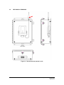
1
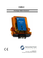
CAN-2 Enrange Radio Receiver January 2014 Part Number: 198-80100-0001 R4 ©Copyright 2014 Magnetek Material Handling Your New Radio Receiver Thank you for your purchase of Magnetek’s EnrangeTM CAN-2 Radio Receiver. Magnetek has set a whole new standard in wireless control performance, dependability, and value with this unique line of Radio Controllers. If your product ever needs modification or service, please contact one of our representatives at the following locations: U.S. Service Information For questions regarding service or technical information contact: 1.866.MAG.SERV (1.866.624.7378) International Service: +1.262.783.3500 Magnetek, Inc. N49 W13650 Campbell Drive Menomonee Falls, WI 53051 Telephone: +1.800.288.8178 Website: e-mail: www.magnetekmobilehydraulic.com [email protected] Fax Numbers: Main: +1.800.298.3503 Sales: +1.262.783.3510 Service: +1.262.783.3508 Canada Service Information: 4090B Sladeview Crescent Mississauga, Ontario L5L 5Y5 Canada Phone: +1.800.792.7253 Fax: +1.905.828.5707 +1.416.424.7617 (27/7 Service pager) EU Market Contact: Brian Preston Magnetek (UK) Ltd. Unit 3 Bedford Business Centre Mile Road Bedford, MK42 9TW UK Phone: +44.1234.349191 Fax: +44.1234.268955 ©2014 MAGNETEK All rights reserved. This notice applies to all copyrighted materials included with this product, including, but not limited to, this manual and software embodied within the product. This manual is intended for the sole use of the person(s) to whom it was provided, and any unauthorized distribution of the manual or dispersal of its contents is strictly forbidden. This manual may not be reproduced in whole or in part by any means whatsoever without the expressed written permission of MAGNETEK. Enrange CAN-2 Instruction Manual January 2014 Page 1 of 33 TABLE OF CONTENTS 1.0 INTRODUCTION .................................................................................................................. 3 1.1 PRODUCT MANUAL SAFETY INFORMATION ............................................................... 3 1.2 WARNINGS and CAUTIONS ............................................................................................ 4 2.0 CRITICAL INSTALLATION CONSIDERATIONS ................................................................. 5 2.1 GENERAL ......................................................................................................................... 5 2.2 PERSONS AUTHORIZED TO OPERATE RADIO CONTROLLED EQUIPMENT ........... 5 2.3 SAFETY INFORMATION & RECOMMENDED TRAINING FOR RADIO CONTROLLED EQUIPMENT OPERATORS ........................................................................................................ 6 2.4 PRE-OPERATION TEST .................................................................................................. 7 3.0 CAN-2 RECEIVER INSTALLATION ..................................................................................... 8 3.1 PRE-INSTALLATION ........................................................................................................ 8 3.2 MECHANICAL DRAWINGS .............................................................................................. 9 3.3 INSTALLATION ............................................................................................................... 10 3.4 REMOVAL OF CAN-2 FROM HOUSING ....................................................................... 11 3.5 CAN TERMINATING RESISTOR SETTING................................................................... 12 3.6 REINSTALLATION OF CAN-2 TO HOUSING ................................................................ 12 3.7 PIN OUT DIAGRAM AND DEFINITIONS ....................................................................... 13 3.8 CONNECTOR COMPONENT INFORMATION .............................................................. 14 4.0 OPERATION ....................................................................................................................... 15 4.1 INITIALIZATION .............................................................................................................. 15 4.2 NORMAL OPERATION................................................................................................... 15 4.3 LED STATUS INDICATION ............................................................................................ 15 4.3.1 RF Messages LED (Labeled RF on CAN-2 Faceplate) ........................................... 15 4.3.2 Signal Strength/Error Code LED (Labeled STATUS on CAN-2 Faceplate) ............ 16 4.3.3 Communication LED (Labeled COM on CAN-2 Faceplate) .................................... 16 4.4 INFRARED COMMUNICATION ..................................................................................... 16 5.0 PROGRAMMING WITH RCP .................................................................................................. 17 5.1 ACCESS CODES ................................................................................................................ 17 5.2 CHANGING TRANSMITTER ACCESS CODES ................................................................. 17 5.3 CONNECTING THE CAN-2 TO A COMPUTER.................................................................. 18 5.4 PROGRAMMING WITH RCP .............................................................................................. 19 5.4.1 CAN-2 Configuration Tabs ............................................................................................ 21 5.4.2 Programming & Other RCP Software Functions ........................................................... 25 6.0 CHANNEL AND FREQUENCY DESIGNATIONS .............................................................. 27 6.1 400 MHz Part 15 ............................................................................................................. 27 6.2 419 MHz Extended Channel Set ..................................................................................... 28 6.3 900 MHz Part 15 ............................................................................................................. 29 6.4 2.4 GHz: FHSS ............................................................................................................... 29 6.5 FCC Statements .............................................................................................................. 30 7.0 TROUBLESHOOTING........................................................................................................ 30 7.1 TROUBLESHOOTING TABLE ....................................................................................... 31 7.2 ASSEMBLY AND REPLACEMENT PARTS ................................................................... 32 8.0 EU DECLARATION OF CONFORMITY .................................................................................. 33 Enrange CAN-2 Instruction Manual January 2014 Page 2 of 33 1.0 INTRODUCTION Thank you for your purchase of Magnetek’s Enrange® brand CAN-2 Radio Wireless Receiver. ® These instructions are to be used as a reference for personnel operating the Enrange brand CAN-2 Radio ® Wireless Receiver and the equipment that this Enrange brand CAN-2 Radio Wireless Receiver is attached to. The user of these instructions should have basic knowledge in the handling of electronic equipment. 1.1 PRODUCT MANUAL SAFETY INFORMATION Magnetek, Inc. (Magnetek) offers a broad range of radio remote control products, control products, adjustable frequency drives, and industrial braking systems for overhead material handling applications. This manual has been prepared by Magnetek to provide information and recommendations for the installation, use, operation and service of Magnetek’s material handling products and systems (Magnetek Products). Anyone who uses, operates, maintains, services, installs or owns Magnetek Products should know, understand and follow the instructions and safety recommendations in this manual for Magnetek Products. The recommendations in this manual do not take precedence over any of the following requirements relating to cranes, hoists and lifting devices: Instructions, manuals, and safety warnings of the manufacturers of the equipment where the radio system is used, Plant safety rules and procedures of the employers and the owners of facilities where the Magnetek Products are being used, Regulations issued by the Occupational Health and Safety Administration (OSHA), Applicable local, state or federal codes, ordinances, standards and requirements, or Safety standards and practices for the overhead material handling industry. This manual does not include or address the specific instructions and safety warnings of these manufacturers or any of the other requirements listed above. It is the responsibility of the owners, users and operators of the Magnetek Products to know, understand and follow all of these requirements. It is the responsibility of the owner of the Magnetek Products to make its employees aware of all of the above listed requirements and to make certain that all operators are properly trained. No one should use Magnetek Products prior to becoming familiar with and being trained in these requirements. WARRANTY INFORMATION FOR INFORMATION ON MAGNETEK’S PRODUCT WARRANTIES BY PRODUCT TYPE, PLEASE VISIT WWW.MAGNETEKMOBILEHYDRAULIC.COM. Enrange CAN-2 Instruction Manual January 2014 Page 3 of 33 1.2 WARNINGS and CAUTIONS Throughout this document WARNING and CAUTION statements have been deliberately placed to highlight items critical to the protection of personnel and equipment. WARNING – A warning highlights an essential operating or maintenance procedure, practice, etc. which if not strictly observed, could result in injury or death of personnel, or long term physical hazards. Warnings are highlighted as shown below: WARNING CAUTION – A caution highlights an essential operating or maintenance procedure, practice, etc. which if not strictly observed, could result in damage to, or destruction of equipment, or loss of functional effectiveness. Cautions are highlighted as shown below: CAUTION WARNINGS and CAUTIONS SHOULD NEVER BE DISREGARDED. The safety rules in this section are not intended to replace any rules or regulations of any applicable local, state, or federal governing organizations. Always follow your local lockout and tagout procedure when maintaining any radio equipment. The following information is intended to be used in conjunction with other rules or regulations already in existence. It is important to read all of the safety information contained in this section before installing or operating the Radio Control System. Enrange CAN-2 Instruction Manual January 2014 Page 4 of 33 2.0 CRITICAL INSTALLATION CONSIDERATIONS WARNING PRIOR TO INSTALLATION AND OPERATION OF THIS EQUIPMENT, READ AND DEVELOP AN UNDERSTANDING OF THE CONTENTS OF THIS MANUAL AND THE OPERATION MANUAL OF THE EQUIPMENT OR DEVICE TO WHICH THIS EQUIPMENT WILL BE INTERFACED. FAILURE TO FOLLOW THIS WARNING COULD RESULT IN SERIOUS INJURY OR DEATH AND DAMAGE TO EQUIPMENT. ALL EQUIPMENT MUST HAVE A MAINLINE CONTACTOR INSTALLED AND ALL TRACKED CRANES, HOISTS, LIFTING DEVICES AND SIMILAR EQUIPMENT MUST HAVE A BRAKE INSTALLED. FAILURE TO FOLLOW THIS WARNING COULD RESULT IN SERIOUS INJURY OR DEATH AND DAMAGE TO EQUIPMENT. AN AUDIBLE AND/OR VISUAL WARNING MEANS MUST BE PROVIDED ON ALL REMOTE CONTROLLED EQUIPMENT AS REQUIRED BY CODE, REGULATION, OR INDUSTRY STANDARD. THESE AUDIBLE AND/OR VISUAL WARNING DEVICES MUST MEET ALL GOVERNMENTAL REQUIREMENTS. FAILURE TO FOLLOW THIS WARNING COULD RESULT IN SERIOUS INJURY OR DEATH AND DAMAGE TO EQUIPMENT. FOLLOW YOUR LOCAL LOCKOUT TAGOUT PROCEDURE BEFORE MAINTAINING ANY REMOTE CONTROLLED EQUIPMENT. ALWAYS REMOVE ALL ELECTRICAL POWER FROM THE CRANE, HOIST, LIFTING DEVICE OR SIMILAR EQUIPMENT BEFORE ATTEMPTING ANY INSTALLATION PROCEDURES. DE-ENERGIZE AND TAGOUT ALL SOURCES OF ELECTRICAL POWER BEFORE TOUCH-TESTING ANY EQUIPMENT. FAILURE TO FOLLOW THIS WARNING COULD RESULT IN SERIOUS INJURY OR DEATH AND DAMAGE TO EQUIPMENT. THE DIRECT OUTPUTS OF THIS PRODUCT ARE NOT DESIGNED TO INTERFACE DIRECTLY TO TWO STATE SAFETY CRITICAL MAINTAINED FUNCTIONS, I.E., MAGNETS, VACUUM LIFTS, PUMPS, EMERGENCY EQUIPMENT, ETC. A MECHANICALLY LOCKING INTERMEDIATE RELAY SYSTEM WITH SEPARATE POWER CONSIDERATIONS MUST BE PROVIDED. FAILURE TO FOLLOW THIS WARNING COULD RESULT IN SERIOUS INJURY OR DEATH OR DAMAGE TO EQUIPMENT. 2.1 GENERAL Radio controlled material handling equipment operates in several directions. Cranes, hoists, lifting devices and other material handling equipment can be large, and operate at high speeds. Quite frequently, the equipment is operated in areas where people are working in close proximity to the material handling equipment. The operator must exercise extreme caution at all times. Workers must constantly be alert to avoid accidents. The following recommendations have been included to indicate how careful and thoughtful actions may prevent injuries, damage to equipment, or even save a life. 2.2 PERSONS AUTHORIZED TO OPERATE RADIO CONTROLLED EQUIPMENT Only properly trained persons designated by management should be permitted to operate radio controlled equipment. Radio controlled cranes, hoists, lifting devices and other material handling equipment should not be operated by any person who cannot read or understand signs, notices and operating instructions that pertain to the equipment. Radio controlled equipment should not be operated by any person with insufficient eyesight or hearing or by any person who may be suffering from a disorder or illness, is taking any medication that may cause loss of equipment control, or is under the influence of alcohol or drugs. Enrange CAN-2 Instruction Manual January 2014 Page 5 of 33 2.3 SAFETY INFORMATION & RECOMMENDED TRAINING FOR RADIO CONTROLLED EQUIPMENT OPERATORS Anyone being trained to operate radio controlled equipment should possess as a minimum the following knowledge and skills before using the radio controlled equipment. The operator should: Have knowledge of hazards pertaining to equipment operation Have knowledge of safety rules for radio controlled equipment Have the ability to judge distance of moving objects Know how to properly test prior to operation Be trained in the safe operation of the radio receiver as it pertains to the crane, hoist, lifting device or other material handling equipment being operated Have knowledge of the use of equipment warning lights and alarms Have knowledge of the proper storage space for a radio control receiver when not in use Be trained in transferring a radio control receiver to another person Be trained how and when to report unsafe or unusual operating conditions Test the receiver emergency stop and all warning devices prior to operation; testing should be done on each shift, without a load Be thoroughly trained and knowledgeable in proper and safe operation of the crane, hoist, lifting device, or other material handling equipment that utilizes the radio control Know how to keep the operator and other people clear of lifted loads and to avoid “pinch” points Continuously watch and monitor status of lifted loads Know and follow cable and hook inspection procedures Know and follow the local lockout and tagout procedures when servicing radio controlled equipment Know and follow all applicable operating and maintenance manuals, safety procedures, regulatory requirements, and industry standards and codes The operator shall not: Lift or move more than the rated load Operate the material handling equipment if the direction of travel or function engaged does not agree with what is indicated on the controller Use the crane, hoist or lifting device to lift, support or transport people Lift or carry any loads over people Operate the crane, hoist or lifting device unless all persons, including the operator, are and remain clear of the supported load and any potential pinch points Operate a crane, hoist or lifting device when the device is not centered over the load Operate a crane, hoist or lifting device if the chain or wire rope is not seated properly in the sprockets, drum or sheave Operate any damaged or malfunctioning crane, hoist, lifting device or other material handling equipment Change any settings or controls without authorization and proper training Remove or obscure any warning or safety labels or tags Enrange CAN-2 Instruction Manual January 2014 Page 6 of 33 Leave any load unattended while lifted Leave power on the radio controlled equipment when the equipment is not in operation Operate any material handling equipment using a damaged controller because the unit may be unsafe Operate manual motions with other than manual power Operate radio controlled equipment when low battery indicator is on WARNING THE OPERATOR SHOULD NOT ATTEMPT TO REPAIR ANY RADIO CONTROLLER. IF ANY PRODUCT PERFORMANCE OR SAFETY CONCERNS ARE OBSERVED, THE EQUIPMENT SHOULD IMMEDIATELY BE TAKEN OUT OF SERVICE AND BE REPORTED TO THE SUPERVISOR. DAMAGED AND INOPERABLE RADIO CONTROLLER EQUIPMENT SHOULD BE RETURNED TO MAGNETEK FOR EVALUATION AND REPAIR. FAILURE TO FOLLOW THIS WARNING COULD RESULT IN SERIOUS INJURY OR DEATH AND DAMAGE TO EQUIPMENT. WARNING TO AVOID ELECTROSTATIC DISCHARGE THAT COULD DAMAGE THE PRODUCT, THE OPERATOR SHOULD AVOID CONTACT WITH THE RECEIVER ANTENNA PORT. 2.4 PRE-OPERATION TEST At the start of each work shift, or when a new operator takes control of the crane, operators should do, as a minimum, the following steps before making lifts with any crane or hoist: Test all warning devices. Test all direction and speed controls. Test the receiver emergency stop. Enrange CAN-2 Instruction Manual January 2014 Page 7 of 33 3.0 CAN-2 RECEIVER INSTALLATION WARNING BEFORE OPERATING THE RECEIVER, FAMILIARIZE YOURSELF WITH ALL SAFETY INFORMATION IN THIS MANUAL, APPROPRIATE MANUAL SUPPLEMENTS AND ANY OTHER LOCAL, STATE, OR FEDERAL RULES OR REGULATIONS ALREADY IN EXISTENCE. FAILURE TO FOLLOW THIS WARNING COULD RESULT IN SERIOUS INJURY OR DEATH AND DAMAGE TO EQUIPMENT. 3.1 PRE-INSTALLATION 1. The transmitter and receiver access code and channel must match before the system will communicate. 2. Be aware of other radio channels in the surrounding area - set your system to a unique channel. 3. Make sure that your equipment is working properly in manual mode prior to system installation. 4. Make sure the power to the receiver is the correct DC voltage. 5. Disconnect equipment power prior to system installation. Enrange CAN-2 Instruction Manual January 2014 Page 8 of 33 3.2 MECHANICAL DRAWINGS Figure 01: Remote Antenna (marked in red) Enrange CAN-2 Instruction Manual January 2014 Page 9 of 33 Figure 02: CAN-2 with external antenna (red) Figure 04: CAN-2 Bottom View 3.3 Figure 03: CAN-2 with internal antenna (red) Figure 05: CAN-2 Side View INSTALLATION 1. 2. 3. 4. 5. 6. 7. Determine the location of your antenna from Figures 01 through 03 (the antenna is designated with the red arrow). Be sure to mount the receiver antenna in direct line-of-sight of the operator and free from all obstructions. Do not mount receiver near high levels of electric noise, such as an unshielded variable frequency drive, as it may cause minor interference. When mounting the CAN-2 near unshielded variable frequency drive, Magnetek typically recommends that the CAN-2 and all antenna cable routing be mounted a minimum of 24 inches from all unshielded variable frequency drives and cables. Allow adequate room for mounting the receiver. Make sure to allow a minimum of 5” between connector and nearest surface to allow for cable harness connections. For best reception and to help protect connectors from moisture and water damage, mount the receiver in an upright position. If obstructions cannot be cleared, or the unit must be mounted inside a metal enclosure, the remote antenna should be used (see Figure 01). Do not enclose the antenna in steel. For best reception, keep all metal objects away from the antenna. Consult the factory for more information regarding your application. The power supply to the CAN-2 system must have a master disconnect. NOTE: Magnetek strongly recommends the use of circuit disconnects for all CAN-2 receivers. Consult factory for more information. Enrange CAN-2 Instruction Manual January 2014 Page 10 of 33 3.4 REMOVAL OF CAN-2 FROM HOUSING It might be necessary to access the internal circuit board on the receiver to adjust the CAN terminating resistor jumper. To remove the CAN-2 receiver from the housing, first remove power from the CAN-2 receiver by turning off the master disconnect. Remove the connectors from the bottom of the receiver by squeezing in the release tabs on both sides of the connector. The bottom connector plate with the internal circuit board is removed by inserting a flat screwdriver into the top slots for the two side release tabs and giving a gentle twist. Figure 06: CAN-2 housing removal procedure After releasing both sides, one at a time, gently pull the circuit board from the housing (this may require gently rocking it side to side as it is being removed). Enrange CAN-2 Instruction Manual January 2014 Page 11 of 33 3.5 CAN TERMINATING RESISTOR SETTING For CAN signaling to work correctly, the first and last devices on the CAN bus must have terminating resistors of 120 ohms. The CAN-2 has a built-in terminating resistor that can be enabled or disabled by a built-in jumper. After removing the CAN-2 receiver from the housing, locate the terminating resistor jumper (P2) on the PCB near the main connector in the lower right, as seen in Figure 07. Figure 07: CAN-2 Terminating Resistor Location Figure 08: Terminating Resistor Setting When the jumper is matched to the “TERM” position the terminating resistor is enabled. When the jumper is in any other position it is disabled. 3.6 REINSTALLATION OF CAN-2 TO HOUSING To reinstall slide the board and connector plate into the housing and press firmly to fully seat the bottom connector plate onto the housing. Enrange CAN-2 Instruction Manual January 2014 Page 12 of 33 3.7 PIN OUT DIAGRAM AND DEFINITIONS Figure 09: Pin out diagram Table 1: Connector Connections PIN 1 2 3 4 5 6 7 8 9 10 11 12 FUNCTION CANL CANH CAN_REF CANL CANH -VBATT +VBATT USB D+ USB DUSB REF OUTPUT2 OUTPUT1 DESCRIPTION CANL CANH Common CANL CANH Common +12-24 VDC Power USB Data USB Data USB Common Output/ESTOP 2 Output/ESTOP 1 +VBATT (Pin 7) The CAN-2 is designed to work in any 12-24 VDC nominal (9-36 VDC max) powered equipment. The +VBATT pins should be connected to the positive terminal of the machine power supply through an approved Emergency Stop device. -VBATT (Pin 6) The -VBATT connections must be made directly to the negative supply and not to the chassis ground. Machine Stop Outputs (Pins 11 and 12) In order to ensure maximum safety of the equipment controlled by the CAN-2, a Machine Stop output is recommended. Pins 11 and 12 can be set as Machine Stop outputs for redundancy, or pin 12 can be set as a single Machine Stop output. Pins 11 and 12 are high side switch outputs that can supply a current of up to 6 Amps per output. When programmed, the pin 11 and 12 outputs (or pin 12 alone) are normally closed and will go to an open state in the event of an unsafe condition, such as loss of communications. Enrange CAN-2 Instruction Manual January 2014 Page 13 of 33 Figure 10: CAN-2 Machine Stop Wiring Additionally, make sure that a Machine Stop is provided elsewhere on the equipment in which the CAN-2 is installed in order to comply with all applicable Machinery Directives. CAN (Pins 1, 2, 4, and 5) There is only one CAN bus on the CAN-2. There are 2 sets of pins to support proper daisy chained connections to a CAN network. CAN Reference (Pin 3) On isolated CAN-2 devices pin 3 should be connected to the common pin of the device using the isolated CAN bus. On non-isolated CAN-2 units this pin can be connected to the system common. 3.8 CONNECTOR COMPONENT INFORMATION Table 2: Connector Part Numbers DEUTCH Connector Information Connector Housing Wedge Lock Crimp (16-22 AWG) Connector Boot Connector Kit (all components above) CAN RX 6’ Harness Assembly DEUTCH Part # DTM06-12SA WM-12S 1062-20-0122-PS DTM12S-BT (Gray) N/A Magnetek Part # 01-525-0029E 01-525-0030E 01-550-0029E 20-990-0092E 25-04-030-163E N/A 25-04-030-173E Enrange CAN-2 Instruction Manual January 2014 Page 14 of 33 4.0 OPERATION During normal operation the CAN-2 receiver will receive commands from the transmitter and convert them to output or CAN signals. During these operations, the operator can verify that the receiver is online and functioning by interpreting the status LED lights on the front of the CAN-2 receiver. If there are errors during operation, the LED lights can help troubleshoot the problem. 4.1 INITIALIZATION During startup of the CAN-2 module, the signal strength/error code LED will illuminate to provide initialization status. Slow Blink Green = Initialization ok, no errors present Blinking Red = Start up initialization error After initialization is complete, the LED will then illuminate the signal strength and error code status as part of the normal operation. 4.2 NORMAL OPERATION During normal operation of the receiver, the receiver will receive commands from the transmitter and convert them into outputs or CAN messages. During operation, the receiver will communicate its status via LEDs. WARNING DO NOT ASSUME THE POWER IS OFF IN THE RECEIVER BECAUSE THE TRANSMITTER IS TURNED OFF. FAILURE TO FOLLOW THIS WARNING COULD RESULT IN SERIOUS INJURY OR DEATH AND DAMAGE TO EQUIPMENT. 4.3 LED STATUS INDICATION The CAN-2 has three LEDs for indicating the CAN-2 status at a glance during normal operation: The center LED labeled STATUS indicates the CAN-2’s signal strength/error codes. The top LED (RF) indicates receiving of RF messages. The bottom LED (COM) indicates received CAN data. 4.3.1 RF Messages LED (Labeled RF on CAN-2 Faceplate) Green Slow Blinks = Transmitter is offline (watchdog indicator) Green Fast Blinks = Each blink is a valid RF message Red Solid = Error occurred; refer to Error Code LED's blink code Enrange CAN-2 Instruction Manual January 2014 Page 15 of 33 4.3.2 Signal Strength/Error Code LED (Labeled STATUS on CAN-2 Faceplate) Solid Green = Good RF signal strength to transmitter Solid Yellow = Average RF signal strength to transmitter Solid Red = Low RF signal strength to transmitter Blinking Red = Error (code is picked up from number of blinks) o Red 2 Blinks – Commanded Power Down o Red 3 Blinks – RF Data Timeout o Red 4 Blinks – CAN bus Timeout o Red 5 Blinks – Initialization / Hardware Error o Red 6 Blinks – Machine Stop Power Down o Red 7 Blinks – Invalid RF Firmware Refer to Section 7.0 for the troubleshooting table to interpret error codes. NOTE: SIGNAL STRENGTH/ERROR CODE LED only illuminates green when the receiver is online with the transmitter. The SIGNAL STRENGTH/ERROR CODE LED will not illuminate green after the transmitter goes offline from the receiver. This can occur when the transmitter powers down from inactivity or goes out of range. The START toggle on the transmitter must be toggled to bring the transmitter back online with the receiver. 4.3.3 Communication LED (Labeled COM on CAN-2 Faceplate) During normal operation, if there is CAN data currently being received on the bus this LED will light solid blue as an indication that the CAN bus is connected properly. 4.4 INFRARED COMMUNICATION The CAN-2 is equipped with an infrared (IR) port that is used when pairing a transmitter with the CAN-2. Please refer to the appropriate transmitter manual for instructions on how to use this feature (if supported by the transmitter). The IR port is accessible when the board is within the housing. There is no need to remove the board from the housing to utilize the IR pairing feature. See Figure 11 for the location of the IR port on the CAN-2. Figure 11: CAN-2 Infrared Port Location (red) Enrange CAN-2 Instruction Manual January 2014 Page 16 of 33 5.0 PROGRAMMING WITH RCP Using the RCP software allows for simple configuration of the CAN-2, and allows for settings to be saved for future reference. WARNING THE USE OF RCP (RADIO CONTROL PROGRAMMER) IS INTENDED FOR USE BY AUTHORIZED PERSONS ONLY. CHANGES TO ANY RADIO DATA VALUE MAY LEAD TO UNEXPECTED, UNDESIRABLE, OR UNSAFE OPERATION OF EQUIPMENT AND FURTHERMORE MAY LEAD TO EQUIPMENT DAMAGE, PERSONAL INJURY, OR EVEN DEATH. ALL EQUIPMENT OPERATORS AND/OR PERSONNEL SHOULD BE NOTIFIED OF ANY RADIO DATA VALUE CHANGES THAT MAY AFFECT OPERATION. 5.1 ACCESS CODES The receiver and transmitter must be programmed with the same access code to properly communicate with each other. WARNING TWO OPERATIONAL TRANSMITTERS WITH THE SAME ACCESS CODES OPERATING AT THE SAME TIME IS A DEFINITE SAFETY HAZARD – DO NOT OPERATE THEM AT THE SAME TIME. FAILURE TO FOLLOW THIS WARNING COULD RESULT IN SERIOUS INJURY OR DEATH AND DAMAGE TO EQUIPMENT. 5.2 CHANGING TRANSMITTER ACCESS CODES Transmitter Access Code Programming. For detailed instructions on setting parameters, including access codes, see the “Programming” section of the applicable transmitter manual. WARNING AFTER CHANGING THE ACCESS CODES ON THE TRANSMITTER, TEST THE UNIT BY TURNING IT ON AND OFF NEAR THE APPROPRIATE RECEIVER. IF THE RECEIVER DOES NOT RESPOND, DO NOT ACTIVATE A FUNCTION BUTTON! THE TRANSMITTER MAY HAVE THE WRONG ACCESS CODE, WHICH COULD MOVE OTHER EQUIPMENT. RE-CHECK THE ACCESS CODE IN THE TRANSMITTER AND RETEST. FAILURE TO FOLLOW THIS WARNING COULD RESULT IN SERIOUS INJURY OR DEATH, AND DAMAGE TO EQUIPMENT. Enrange CAN-2 Instruction Manual January 2014 Page 17 of 33 WARNING THE ACCESS CODES IN THE RECEIVER ARE UNIQUE AND FACTORY PRESET. DO NOT CHANGE THESE ACCESS CODES UNLESS YOU ARE REPLACING AN EXISTING RECEIVER AND ITS ACCESS CODE. CHANGING THIS CODE COULD MAKE IT COMMON WITH ANOTHER RECEIVER ACCESS CODE, WHICH COULD MOVE OTHER EQUIPMENT. NO TWO SYSTEMS IN ANY LOCATION SHOULD EVER HAVE THE SAME ACCESS CODES INDEPENDENT OF THE FREQUENCY. FAILURE TO FOLLOW THIS WARNING COULD RESULT IN SERIOUS INJURY OR DEATH, AND DAMAGE TO EQUIPMENT. 5.3 CONNECTING THE CAN-2 TO A COMPUTER The CAN-2 receiver contains circuits that permit communication with a computer system via USB. If the CAN-2 receiver was ordered with the Pre-Wired Cable kit, the 195-50539 USB cable can be added by simply plugging in the connector. This option provides a USB-mini B plug for connection to a computer system. If not using the CAN-2 Pre-Wired Cable Kit, the CAN-2 can be wired for USB connection using the pin outs in the figure below. Figure 12: USB Connection Wiring When plugging in a CAN-2 receiver to a computer system, it is strongly recommended that a USB isolation hub, like Magnetek part 195-50645, is used between the CAN-2 and the computer system. Enrange CAN-2 Instruction Manual January 2014 Page 18 of 33 WARNING CAN-2 RECEIVERS UTILIZING A DIFFERENT POWER SOURCE FROM THE COMPUTER SYSTEM BEING CONNECTED TO IT CAN HAVE A DIFFERENT GROUND POTENTIAL FROM THE COMPUTER SYSTEM. DIFFERENT GROUND POTENTIALS WILL DAMAGE EITHER THE COMPUTER SYSTEM OR THE CAN-2 RECEIVER. AN ISOLATED USB HUB MUST BE UTILIZED TO PREVENT DAMAGE TO THE CAN-2, THE COMPUTER SYSTEM BEING CONNECTED TO THE CAN-2, OR BOTH. 5.4 PROGRAMMING WITH RCP Magnetek RCP software makes the programming of the CAN-2 receiver easier and allows the programmer to store all of the CAN-2 settings in files for later use or reference. Help is provided for each function at the bottom of the RCP screen. The RCP software allows one to select frequency, access code, and communication configuration. Follow the steps below: Install the RCP Software Install the RCP software onto your computer. The software is self-installing; simply insert the USB stick into a USB slot on your computer and follow the onscreen prompts. Refer to the installation instruction sheet for help. You will be prompted to enter an activation code. The code can be found within the packaging that the USB stick came with. The software can be used 10 times before product activation is required. Run the RCP Software After installation of the RCP Software, double-click the RCP icon to launch the program. New Project or Open Project Select “New Project” if you are creating a new program file, or select “Open Project” if you want to retrieve an existing program file. A list of recent projects will appear under “Open Project”. Clicking on one of these will open that project. It is recommended that you create a folder in which to save all programming files. Enrange CAN-2 Instruction Manual January 2014 Page 19 of 33 For New Projects, Select Device Type After the New Projects icon is selected, a menu will open listing the available device types. Select the device type that matches the product you wish to program (selecting a project type will display a picture of the product for verification). Receive Device Data Checkbox At the bottom of the New Project window there is a check box that allows the system to automatically upload the setting values from the device upon connection. NOTE: This check box is selected by default. Having the “Receive Device Data” option checked will cause the program to automatically read the data that is currently on the device upon clicking the Add button. Enrange CAN-2 Instruction Manual January 2014 Page 20 of 33 WARNING IF THE “RECEIVE DEVICE DATA” CHECK BOX IS UNCHECKED, THE RCP PROGRAM WILL OVERWRITE ALL SETTING VALUES ON THE DEVICE WITH DEFAULT VALUES AND ANY SETTINGS CHANGED BY THE OPERATOR UPON SENDING THE PROGRAM TO THE DEVICE. ALL STORED VALUE SETTINGS WITHIN THE DEVICE WILL BE REPLACED, INCLUDING ANY PROJECT-SPECIFIC VALUES. MAGNETEK STRONGLY RECOMMENDS THAT THE “RECEIVE DEVICE DATA” CHECK BOX BE LEFT CHECKED. This screen also allows the programmer to create a specific name for the device to help keep track of device settings and changes. It is recommended that a unique name is chosen for each device programmed with RCP. 5.4.1 CAN-2 Configuration Tabs The CAN-2 Receiver has up to three configuration tabs that are used to configure and program the device. The first tab is the Unit Info tab which permits configuration of general settings as well as the CAN port configuration. The second tab is the Programming tab which permits custom Enrange CAN-2 Instruction Manual January 2014 Page 21 of 33 programming of the device. The third tab is the FDP tab which is used to program new firmware into the device. For more information on the Programming and FDP tabs, please refer to the RCP User Guide. Unit Info Tab This page allows the user to view the receiver Project ID and serial number. The user can modify the receiver name, access code, RF channel, receiver timeout, and whether to use an internal or external RF antenna. CAN bus properties are able to be set in this page as well. NOTE: Changing any of these details will require a reboot of the CAN-2 after the new information has been sent to the device. The Unit Info page is divided into three sections. The leftmost section is the Unit Info Properties grid. The middle section, which is the Device Block Diagram, shows the pinout of the unit and each pin’s function. Clicking on a pin or function will show any configurable properties in the Pin Properties Grid, which is the rightmost section. Each of these sections is described in greater detail on the next page. Enrange CAN-2 Instruction Manual January 2014 Page 22 of 33 Unit Info Properties Frequency This field displays the operating frequency band of the receiver. The receiver Radio Frequency is set by the factory and cannot be modified by the user. Access Code The access code acts as the receiver address. The receiver will only listen to transmitters with the same access code. This feature is selectable by the user. NOTE: The transmitter must be set with the same access code as the receiver to properly communicate with each other. WARNING THE ACCESS CODES IN THE RECEIVER ARE UNIQUE AND FACTORY PRESET. DO NOT CHANGE THESE ACCESS CODES UNLESS YOU ARE REPLACING AN EXISTING RECEIVER AND ITS ACCESS CODE. CHANGING THIS CODE COULD MAKE IT COMMON WITH ANOTHER RECEIVER ACCESS CODE, WHICH COULD MOVE OTHER EQUIPMENT. NO TWO SYSTEMS IN ANY LOCATION SHOULD EVER HAVE THE SAME ACCESS CODES INDEPENDENT OF FREQUENCY. FAILURE TO FOLLOW THIS WARNING COULD RESULT IN SERIOUS INJURY OR DEATH, AND DAMAGE TO EQUIPMENT. RF Channel The RF channel is user selectable through the pull down menu. This function is used to prevent interference with other radio devices. Refer to Section 6 for information about the selectable channels for each frequency band. Enrange CAN-2 Instruction Manual January 2014 Page 23 of 33 RF Antenna This section allows the user to select between using the internal antenna that is built into the receiver or using the external antenna attachment (if available). NOTE: Selecting the external antenna when one isn’t available will result in reduced RF performance. Rx Timeout The Rx Timeout is the amount of time the unit will keep the machine stop outputs closed after the receiver has stopped receiving data from the transmitter. Device Name The device name field allows the user to create a custom name for the unit. The name can be up to 16 ASCII characters long. Project ID This section displays the Project ID for the unit. The Project ID is set by the factory and cannot be modified by the user. Serial Number This section displays the serial number for the unit. The serial number of the unit is set by the factory and cannot be modified by the user. Pin Properties Grid By clicking on one of the CAN functions in the Device Block Diagram, the Pin Properties Grid will permit the user to change the configuration of the CAN interfaces. Source Address This is the address that the CAN-2 will use as the source address when transmitting messages on the CAN-bus network. Baud Rate This pull-down menu allows the user to modify the communication speed of the CAN bus network. The user selectable options are 50k, 125k, 250k, and 500k. Enrange CAN-2 Instruction Manual January 2014 Page 24 of 33 5.4.2 Programming & Other RCP Software Functions NOTE: To program or read data from the CAN-2 the receiver must be turned on. Saving the Programming File Once programming is complete click the file tab at the top of the RCP screen to open the file menu. File location and name can be selected from this menu. Old files can be deleted, called up, modified and renamed by this same menu. Sending a Program to the CAN-2 WARNING AFTER EVERY PROGRAMMING OF THE RECEIVER, TEST THE UNIT BY UTILIZING THE APPROPRIATE TRANSMITTER. IF THE RECEIVER DOES NOT RESPOND, DO NOT ACTIVATE A FUNCTION BUTTON! THE RECEIVER MAY HAVE INCORRECT PROGRAMMING. RE-CHECK THE PROGRAMMING IN THE RECEIVER AND RETEST. AFTER ACTIVATION OF THE RECEIVER, FUNCTIONALLY TEST ALL COMMANDS ON THE TRANSFORMER BY INITIALLY JOGGING THE BUTTONS, THEN WITH A FULL MOVEMENT BEFORE RETURNING TO SERVICE. FAILURE TO FOLLOW THIS WARNING COULD RESULT IN SERIOUS INJURY OR DEATH AND DAMAGE TO EQUIPMENT. To send a program file to an CAN-2 Receiver 1. Plug in the USB programming cable or position. 2. Click the send button on the RCP screen. A dialog box will pop up confirming that you want to proceed. Check the box marked “I accept,” and then click the button “Continue send to radio.” On-screen prompts will confirm that the receiver has been programmed or if there are any issues. 3. Data will need to be sent separately for the Unit Info and CAN Configuration screens. 4. The LEDs on the unit will blink three times when the new data is received and saved. Receiving (Reading) the CAN-2 Programming To read a program file from the CAN-2 Receiver: 1. Plug in the USB programming cable. 2. Click “Receive” and follow on-screen prompts. 3. RCP will confirm reception and automatically display current programming in the CAN-2 unit. Enrange CAN-2 Instruction Manual January 2014 Page 25 of 33 Reading the RCP Software Version 1. Select “Help.” 2. Select “About.” 3. RCP Software Version number will be displayed. Resetting CAN-2 Back to Factory Default Settings 1. Select the “Reset to Defaults” button. 2. A dialog box will pop up confirming that you want to proceed. Click the button “OK” to restore the factory default settings. On-screen prompts will confirm that the receiver has been reset to defaults or if there are any issues. 3. Power cycle the CAN-2 receiver to implement the factory default values. Enrange CAN-2 Instruction Manual January 2014 Page 26 of 33 6.0 CHANNEL AND FREQUENCY DESIGNATIONS 6.1 400 MHz Part 15 Table 3: 400MHz Channels Channel Designator 01 02 03 04 05 06 07 08 09 10 11 12 13 14 15 16 17 18 19 20 21 22 23 24 25 26 27 28 29 30 31 32 Frequency 433.000 MHz 433.050 MHz 433.100 MHz 433.150 MHz 433.200 MHz 433.250 MHz 433.300 MHz 433.350 MHz 433.400 MHz 433.450 MHz 433.500 MHz 433.550 MHz 433.600 MHz 433.650 MHz 433.700 MHz 433.750 MHz 433.800 MHz 433.850 MHz 433.900 MHz 433.950 MHz 434.000 MHz 434.050 MHz 434.100 MHz 434.150 MHz 434.200 MHz 434.250 MHz 434.300 MHz 434.350 MHz 434.400 MHz 434.450 MHz 434.500 MHz 434.550 MHz Enrange CAN-2 Instruction Manual January 2014 Page 27 of 33 6.2 419 MHz Extended Channel Set Table 4: 419MHz Channels Channel Designator 1* 2* 3* 4* 5* 6* 7* 8* 9* 10* 11* 12* 13* 14 15 16 17 18 19 20 21 22 23 24 25 26 27 28 29 30 31 32 33 34 35 36 37 38 39 40 41 42 43 Frequency 418.950 418.975 419.000 419.025 419.050 419.075 419.100 419.125 419.150 419.175 419.200 419.250 419.275 416.000 416.050 416.100 416.150 416.200 416.250 416.300 416.350 416.400 416.450 416.500 416.550 416.600 416.650 416.700 416.750 416.800 416.850 416.900 416.950 417.000 417.050 417.100 417.150 417.200 417.250 417.300 417.350 417.400 417.450 Channel Designator 44 45 46 47 48 49 50 51 52 53 54 55 56 57 58 59 60 61 62 63 64 65 66 67 68 69 70 71 72 73 74 75 76 77 78 79 80 81 82 83 84 85 -- Frequency 417.500 417.550 417.600 417.650 417.700 417.750 417.800 417.850 417.900 417.950 418.000 418.050 418.100 418.150 418.200 418.250 418.300 418.350 418.400 418.450 418.500 418.550 418.600 418.650 418.700 418.750 418.800 418.850 418.900 419.350 419.400 419.450 419.500 419.550 419.600 419.650 419.700 419.750 419.800 419.850 419.900 419.950 -- NOTE: Channels marked with * are approved for use in China. Enrange CAN-2 Instruction Manual January 2014 Page 28 of 33 6.3 900 MHz Part 15 Table 5: 900MHz Channels Channel Designator 1 2 3 4 5 6 7 8 A B C D E F G H I J K L M N O P Q R S T U V W X 6.4 Frequency 903.30 MHz 906.30 MHz 907.80 MHz 909.30 MHz 912.30 MHz 915.30 MHz 919.80 MHz 921.30 MHz 902.30 MHz 904.10 MHz 904.30 MHz 905.10 MHz 905.50 MHz 905.70 MHz 906.60 MHz 908.70 MHz 908.90 MHz 909.10 MHz 910.10 MHz 910.70 MHz 911.00 MHz 911.20 MHz 912.00 MHz 914.20 MHz 914.40 MHz 914.60 MHz 914.80 MHz 915.80 MHz 917.40 MHz 923.20 MHz 927.00 MHz 927.30 MHz 2.4 GHz: FHSS Channel sets are designated between 1 and 32. The frequency range is between 2402-2478 MHz. The frequency hopping protocol does not use one particular frequency to transmit a message. Messages are transmitted over multiple frequencies in a predefined sequence or channel set. In doing so, this protocol is able to compensate for interference that may be present on a single frequency by sending the message across multiple frequencies. Enrange CAN-2 Instruction Manual January 2014 Page 29 of 33 6.5 FCC Statements Compliance Statement (Part 15.19) This device complies with Part 15 of FCC rules. Operation is subject to the following two conditions: 1. This device may not cause harmful interference, and 2. This device must accept any interference received, including interference that may cause undesired operation. This portable transmitter with its antenna complies with FCC’s RF exposure limits for general population/uncontrolled exposure. Warning (Part 15.21) Changes or modifications not expressly approved by the party responsible for compliance should void the user’s authority to operate the equipment. Enrange CAN-2 Instruction Manual January 2014 Page 30 of 33 7.0 TROUBLESHOOTING 7.1 TROUBLESHOOTING TABLE Problems Receiver will not turn on Possible Reasons Suggestions Supplied voltage is out of the Ensure the voltage is within 12-24VDC acceptable range nominal (9-36VDC max). Internal fuse has blown Incorrect system RF channel Contact the factory. Make sure the receiver and transmitter unit are both set to the same RF channel. Incorrect system access Make sure the receiver and transmitter both code have the same access code. Make sure that the startup procedure is initiated within 300 feet from the receiver System out of range location. If equipped with the Signal Strength Indicator, make sure the level is Receiver will not respond to the Transmitter greater than 0%. The antenna on the receiver is missing, damaged, or improperly installed Inspect the antenna on the receiver for damage and try to place the antenna in a location that is visible when operating the equipment at all times. The antenna setting on the Make sure the antenna setting (internal or receiver is incorrect external) is for the antenna type being used. An input on the transmitter is Make sure all toggles and motions are in active upon powering up their correct positions. Enrange CAN-2 Instruction Manual January 2014 Page 31 of 33 The CAN message being CAN messages are not being received by the receiver sent is not supported Outputs not functioning update. Verify that the setting of the terminating incorrect value resistor is correct for the application. Incorrect source address Ensure the correct baud rate is set by all devices on the bus. Make sure that the source address of the receiver is set correctly. The termination resistor is Ensure the termination resistor is set incorrectly appropriately set. Incorrect baud rate Faulty Wiring Output is shorted or opened 7.2 your supplier to inquire about a software Termination resistor has an Incorrect baud rate CAN messages transmitted by the receiver are not being received Use the supported messages OR contact Ensure the correct baud rate is set by all devices on the bus. Check all wires for loose or damaged connections. Check all wires and connections for damaged insulation. ASSEMBLY AND REPLACEMENT PARTS If your receiver ever needs repair, we always recommend that you have Magnetek perform the repair. If you need to refer to a parts list, refer to your receiver’s drawing that was included in the shipment of your receiver. Please contact Magnetek’s service department at 1.866.MAG.SERV for information regarding parts and service. Enrange CAN-2 Instruction Manual January 2014 Page 32 of 33 8.0 EU DECLARATION OF CONFORMITY Enrange CAN-2 Instruction Manual January 2014 Page 33 of 33