1
HighWire-MTP2
Software Reference
Rev. 1.2, September 4, 2002
Primary Text Number M8245
SBE, Inc.
2305 Camino Ramon, Suite 200, San Ramon, California 94583
(925) 355-2000
Technical Support (800) 444-0990
Fax: (925) 355-2020
FaxBack Service: (800) 214-4723
website: http://www.sbei.com
Copyright ©2001, 2002 by Data Connection Limited, Inc. All rights reserved.
Copyright ©2001, 2002 by SBE, Inc. All rights reserved.
No part of this manual may be reproduced by any means without written
permission from SBE, Inc., except that the purchaser may copy necessary
portions for internal use only.
While every effort has been made to ensure the accuracy of this manual, SBE
cannot be held responsible for damage resulting from information herein. All
specifications are subject to change without notice.
SBE, Inc. and the SBE logo are trademarks of SBE, Inc.
Sun, Sun Microsystems, the Sun Logo, and Solaris are trademarks or
registered trademarks of Sun Microsystems, Inc. in the United States and
other countries.
VxWorks is a registered trademark of Wind River Systems, Inc.
About SBE, Inc. SBE, Inc., provides a broad range of intelligent communications
controllers used primarily in networking systems applications. These products
are sold worldwide through direct sales and distribution channels.
SBE is based in San Ramon, California, and can be reached at 925-355-2000
or online at http://www.sbei.com
2
HighWire-MTP2 Software Reference - 1.2, September 4, 2002
Contents
1. About This Manual ..................................................................................................................................... 9
1-1. Related Documents ..............................................................................................................................9
1-2. Documentation Conventions ................................................................................................................9
2. Software Installation and Removal ........................................................................................................11
2-1. Software Installation .......................................................................................................................... 11
2-2. Software Removal .............................................................................................................................. 12
2-3. Hot Plug Overview .............................................................................................................................. 12
2-3-1.Terminology .......................................................................................................................... 13
2-3-2.RCM overview ........................................................................................................................ 13
2-3-3.hw_daemon monitoring of hardware status ....................................................................... 13
2-3-4.Daemon assignment ............................................................................................................ 14
2-3-5.Configure a board for basic hot swap ................................................................................. 14
2-3-6.Remove a basic hot swap enabled board ........................................................................... 14
2-3-7.Sample -pkgadd- command output ..................................................................................... 15
2-3-8.Sample -pkgrm- command output ....................................................................................... 20
3. Introduction to HighWire-MTP2 ..............................................................................................................25
3-1. HW400 Boards ................................................................................................................................... 25
3-1-1.HW400c ................................................................................................................................. 25
3-1-2.HW400p ................................................................................................................................ 26
3-2. HW-MTP2 Interface Overview ............................................................................................................ 27
3-3. Theory of Operation ............................................................................................................................ 28
4. Cross Bus Interface .................................................................................................................................29
4-1. Functional Overview ........................................................................................................................... 29
4-1-1.HWMTP2 for Solaris .............................................................................................................. 29
4-1-2.HWMTP2 for SDK .................................................................................................................. 30
4-2. Using the Cross Bus Interface ........................................................................................................... 30
4-2-1.Initialization and termination ............................................................................................... 30
4-2-2.Opening and closing a connection to a line card ............................................................... 30
4-2-3.Opening and closing a sub-interface ................................................................................... 30
4-2-4.Connecting to and disconnecting from an MTP2 instance ................................................ 31
4-2-5.Sending messages to MTP2 ................................................................................................ 31
4-2-6.Receiving messages from MTP2 ......................................................................................... 32
4-2-7.Send-side flow control (HWMTP2 for Solaris only) ............................................................. 32
4-2-8.Receive-side flow control ...................................................................................................... 33
4-3. Basic Interface Functions and API Calls ........................................................................................... 34
4-3-1.cbi_initialize ........................................................................................................................... 34
4-3-2.cbi_terminate ........................................................................................................................ 35
4-3-3.cbi_open ................................................................................................................................ 35
4-3-4.cbi_close ................................................................................................................................ 36
4-3-5.cbi_recv ................................................................................................................................. 36
4-3-6.cbi_send ................................................................................................................................ 37
HighWire-MTP2 Software Reference - 1.2, September 4, 2002
Contents
3
4-3-7.CBI_MSG_AVAIL_CALLBACK ................................................................................................ 38
5. HW-MTP2 Level 2 - Level 3 Interfaces and Message Flows .................................................................39
5-1. Level 2 - Level 3 Management Interface .......................................................................................... 39
5-2. Level 2 - Level 3 Data Interface ........................................................................................................ 40
5-3. Message Flows ................................................................................................................................... 41
5-3-1.Link activation ....................................................................................................................... 42
5-3-2.Remote Processor Outage (RPO) ......................................................................................... 43
5-3-3.Changeover following local detection of link failure ........................................................... 46
5-3-4.Failover of MTP3 Control Part .............................................................................................. 47
5-3-5.MTP3 Data Part failure ......................................................................................................... 48
5-3-6.MTP3 Data Part unavailability .............................................................................................. 48
6. CBI Buffer Formats ..................................................................................................................................49
6-1. Common Header Sub-Structures ...................................................................................................... 49
6-1-1.CBI_M2_COMMON_PARMS ................................................................................................. 49
6-1-2.CBI_M2_MTP2_PARMS ........................................................................................................ 52
6-1-3.CBI_M2_SAAL_PARMS ......................................................................................................... 57
6-1-4.CBI_PKT_HDR ....................................................................................................................... 57
6-2. CBI Message Summary ...................................................................................................................... 57
6-2-1.Signals sent from L3 to L2 ................................................................................................... 57
6-2-2.Signals sent from L2 to L3 ................................................................................................... 59
6-3. CBI Messages: Detailed Description ................................................................................................ 61
6-3-1.CBI_M2_AVAILABLE .............................................................................................................. 61
6-3-2.CBI_M2_BSNT ....................................................................................................................... 61
6-3-3.CBI_M2_BSNT_NOT_RETRIEVABL ....................................................................................... 62
6-3-4.CBI_M2_CLEAR_RTB ............................................................................................................ 62
6-3-5.CBI_M2_CLOSE ..................................................................................................................... 63
6-3-6.CBI_M2_CONTINUE .............................................................................................................. 63
6-3-7.CBI_M2_CREDIT .................................................................................................................... 64
6-3-8.CBI_M2_CREDIT_ERROR ..................................................................................................... 65
6-3-9.CBI_M2_EMERGENCY .......................................................................................................... 65
6-3-10.CBI_M2_EMERGENCY_
CEASES ............................................................................................................................................ 66
6-3-11.CBI_M2_EV_INDICATION .................................................................................................... 66
6-3-12.CBI_M2_EV_REGISTER ...................................................................................................... 68
6-3-13.CBI_M2_EV_UNREGISTER ................................................................................................. 70
6-3-14.CBI_M2_FLUSH_BUFFERS ................................................................................................. 71
6-3-15.CBI_M2_IN_SERVICE ......................................................................................................... 72
6-3-16.CBI_M2_LINK_
CONGESTED .................................................................................................................................... 72
6-3-17.CBI_M2_LINK_CONGSTN_CEASED ................................................................................... 73
6-3-18.CBI_M2_LOC_PROCSSR_
OUTAGE ............................................................................................................................................ 73
6-3-19.CBI_M2_LOC_PROCSSR_
RECOVRD ......................................................................................................................................... 74
6-3-20.CBI_M2_REGISTER ............................................................................................................. 74
4
Contents
HighWire-MTP2 Software Reference - 1.2, September 4, 2002
6-3-21.CBI_M2_UNREGISTER ........................................................................................................ 76
6-3-22.CBI_M2_MSG_FOR_
XMISSION ........................................................................................................................................ 77
6-3-23.CBI_M2_OPEN .................................................................................................................... 78
6-3-24.CBI_M2_OUT_OF_SERVICE ................................................................................................ 80
6-3-25.CBI_M2_QUERY_CONFIG ................................................................................................... 81
6-3-26.CBI_M2_QUERY_STATS ..................................................................................................... 82
6-3-27.CBI_M2_QUERY_STATUS ................................................................................................... 86
6-3-28.CBI_M2_RB_CLEARED ....................................................................................................... 89
6-3-29.CBI_M2_RECEIVED_
MESSAGE ........................................................................................................................................ 90
6-3-30.CBI_M2_REM_PROCSSR_OUTAGE ................................................................................... 91
6-3-31.CBI_M2_REM_PROCSSR_
RECOVRD ......................................................................................................................................... 91
6-3-32.CBI_M2_RETRIEVAL_
COMPLETE ....................................................................................................................................... 92
6-3-33.CBI_M2_RETRIEVAL_NOT_POSS ....................................................................................... 92
6-3-34.CBI_M2_RETRIEVAL_REQ_
FSNC ................................................................................................................................................ 93
6-3-35.CBI_M2_RETRIEVED_
MESSAGE ........................................................................................................................................ 93
6-3-36.CBI_M2_RETRIEVE_BSNT .................................................................................................. 94
6-3-37.CBI_M2_RTB_CLEARED ..................................................................................................... 94
6-3-38.CBI_M2_START ................................................................................................................... 95
6-3-39.CBI_M2_STOP ..................................................................................................................... 95
6-3-40.CBI_M2_UNAVAILABLE ....................................................................................................... 96
6-3-41.CBI_M2_UPDATE_PARMS .................................................................................................. 96
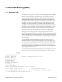
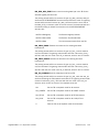
7. Data Path Routing (DPR) .........................................................................................................................99
7-1. dprservice (7D) ................................................................................................................................... 99
Synopsis .......................................................................................................................................... 99
Availability ...................................................................................................................................... 100
Commands .................................................................................................................................... 100
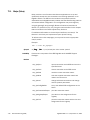
7-2. libdpr (3sbe) ..................................................................................................................................... 116
Synopsis ........................................................................................................................................ 116
Availability ...................................................................................................................................... 116
Routines ........................................................................................................................................ 116
7-3. sbe_dprOpen .................................................................................................................................... 117
Synopsis ........................................................................................................................................ 117
Return values ................................................................................................................................ 117
See also ......................................................................................................................................... 117
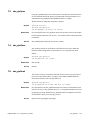
7-4. sbe_dprClose .................................................................................................................................... 117
Synopsis ........................................................................................................................................ 117
Return values ................................................................................................................................ 117
See also ......................................................................................................................................... 117
7-5. sbe_dprRead .................................................................................................................................... 117
HighWire-MTP2 Software Reference - 1.2, September 4, 2002
Contents
5
Synopsis ........................................................................................................................................ 117
Return values ................................................................................................................................ 117
See also ......................................................................................................................................... 117
7-6. sbe_dprWrite .................................................................................................................................... 118
Synopsis ........................................................................................................................................ 118
Return values ................................................................................................................................ 118
See also ......................................................................................................................................... 118
7-7. sbe_dprIoctl ...................................................................................................................................... 118
Synopsis ........................................................................................................................................ 118
Commands .................................................................................................................................... 118
Return values ................................................................................................................................ 128
See also ......................................................................................................................................... 128
7-8. sbe_dprConfigDefault ...................................................................................................................... 129
Synopsis ........................................................................................................................................ 129
Return values ................................................................................................................................ 129
See also ......................................................................................................................................... 129
7-9. sbe_dprConnectionReport ............................................................................................................... 129
Synopsis ........................................................................................................................................ 129
Return values ................................................................................................................................ 129
See also ......................................................................................................................................... 129
7-10. sbe_dprHighwayReport ................................................................................................................. 129
Synopsis ........................................................................................................................................ 129
Return values ................................................................................................................................ 129
See also ......................................................................................................................................... 129
7-11. sbe_dprPrint ................................................................................................................................... 130
Synopsis ........................................................................................................................................ 130
Return values ................................................................................................................................ 130
See also ......................................................................................................................................... 130
8. Appendix A: Test and Library Files ....................................................................................................... 131
8-1. CBI Files ............................................................................................................................................ 131
8-1-1.CBI library source files (for Solaris) ................................................................................... 131
8-1-2.CBI include files (for Solaris) .............................................................................................. 131
8-1-3.CBI include files (for SDK) .................................................................................................. 131
8-1-4.CBIPTEST program (for Solaris) ......................................................................................... 131
8-1-5.Utility files ............................................................................................................................ 131
8-1-6.cbiDemo program ............................................................................................................... 131
8-2. Compiling the CBIPTEST Program ................................................................................................... 132
8-3. Running the CBIPTEST Program ...................................................................................................... 132
8-4. Compiling the cbiDemo Program under SDK ................................................................................. 133
8-5. Running the cbiDemo Program under SDK .................................................................................... 133
8-6. Compiling cbiDemo Program under Solaris ................................................................................... 133
8-7. Running the cbiDemo Program under Solaris ................................................................................ 133
8-8. CBIPTEST Program Console Printout .............................................................................................. 133
8-9. cbiDemo Program Console Printout ................................................................................................ 135
9. Appendix B: Code Values ...................................................................................................................... 137
6
Contents
HighWire-MTP2 Software Reference - 1.2, September 4, 2002
9-1. CBI Function Return Codes ............................................................................................................. 137
9-2. CBI Return Codes ............................................................................................................................. 138
9-3. CBI_YES_NO ..................................................................................................................................... 138
9-4. CBI_MTP2_IPS_TYPES ..................................................................................................................... 139
9-5. CBI_M2_MAJOR_VARIANT ............................................................................................................... 140
9-6. CBI_M2_LPO_STATES ...................................................................................................................... 141
9-7. CBI_M2_UPS_TYPES ........................................................................................................................ 141
9-8. CBI_M2_PS_PROVING_TYPES ......................................................................................................... 141
9-9. CBI_M2_EV_TYPES .......................................................................................................................... 142
9-10. CBI_M2_UPDATE_TYPES ............................................................................................................... 142
9-11. CBI_M2_CONG_LEVELS ................................................................................................................ 143
9-12. CBI_CONG_CTRL ............................................................................................................................ 143
9-13. CBI_ERR_METHOD ........................................................................................................................ 143
9-14. CBI_XMIT_RATE .............................................................................................................................. 144
9-15. CBI_IN_SERVICE_MONITOR_TYPES ............................................................................................. 144
9-16. CBI_M2_LINK_STATUS .................................................................................................................. 144
9-17. L1_FRAMING .................................................................................................................................. 145
9-18. L1_CLOCKING ................................................................................................................................ 145
9-19. L1_LINE_TYPE ................................................................................................................................ 145
9-20. L1_LINE_CODE ............................................................................................................................... 146
9-21. L1_LINE_BUILD_OUT ..................................................................................................................... 146
10. Appendix C: Manpages ....................................................................................................................... 147
10-1. Table of Manpages ........................................................................................................................ 147
11. Appendix: cbiDemo.c and dprDemo.c ............................................................................................... 149
11-1. cbiDemo.c ....................................................................................................................................... 149
11-2. dprDemo.c ...................................................................................................................................... 149
HighWire-MTP2 Software Reference - 1.2, September 4, 2002
Contents
7
Figures
3-1
3-2
5-1
5-2
5-3
5-4
5-5
5-6
5-7
5-8
5-9
HW-MTP2 Level2 - Level 3 interfaces..................................................................................................... 27
HighWire-MTP2 theory of operation........................................................................................................ 28
Message flows involved in registering with an L2 process and activating a link. ............................... 42
Message flows involved when the remote end of the link suffers a processor outage. .................... 43
Message flows involved when the remote end of the link suffers a processor outage. ..................... 44
Message flows involved when the remote end of the link suffers a processor outage. ..................... 44
Message flows involved when the remote end of the link suffers a processor outage. ..................... 45
Message flows involved when L2 detects that a link has failed........................................................... 46
Message flows involved after failover of the control part of MTP3 has occurred. .............................. 47
Message flows involved when the data part of MTP3 fails and is immediately replaced. ................. 48
Message flows involved when the data part of MTP3 fails and is not immediately replaced............ 48
Tables
4-1 Sequence of events in disconnections................................................................................................... 31
10-1 Manpages ............................................................................................................................................... 147
8
Contents
HighWire-MTP2 Software Reference - 1.2, September 4, 2002
1. About This Manual
This manual enables a third party to write applications making use of the
MTP2 protocol executing on SBE’s HW400 board.
The HighWire-MTP2 Software Reference manual covers the following topics:
• Software installation
• Cross Bus Interface
• MTP Layer 2 - Layer 3 management interface
• MTP Layer 2 - Layer 3 data interface
1-1. Related Documents
• HighWire™ HW400c High-Performance Compact PCI Communications
Controller Hardware Technical Reference
• HW400p High-Performance PCI Communications Controller Hardware
Technical Reference
• HW400 Product Series Software Development Kit (SDK) Software
Technical Reference
• ITU Q.700 Series Specifications
• ANSI T1.100, T1.111
1-2. Documentation Conventions
Registers
Signals
Register bits are numbered starting with 0. Bit 0 is the
least significant and bit 7 is the most significant bit of a
byte. Unless otherwise noted, register bits that are
identified as “unused” do not affect the function of the
register, and, if read, yield no information.
When referring to a signal function in text, signal names do
not indicate polarity, and the / is not used. Occasionally a
signal name may be followed by an asterisk (*), a pound
sign (#) after the name, or with a / in front of the signal
name. These are valid ways of indicating active low signals.
Code Code is represented in New Courier
typeface.
HighWire MTP-2 - 1.2, September 4, 2002
Related Documents
9
10
About This Manual
HighWire MTP-2 - 1.2, September 4, 2002
2. Software Installation and Removal
2-1. Software Installation
Software packages contained on the CDROM within the /cdrom/pkg directory
reflect the Solaris operating system version with which the software is
associated.
• hw6mtp_ga_1_0.sbe
• hw8mtp_ga_1_0.sbe
• hw9mtp_ga_1_0.sbe
hw9 reflects Solaris 9; hw8 reflects Solaris 8; hw6 reflects Solaris 2.6. The
ga_X_X portion indicates that the package is an General Access product with
a release level of 1.0.
The following example demonstrates installation of the Solaris 8 HighWire
MTP2 package. Other packages are similarly installed.
1. Install the boards into the system.
2. Log in as root. You must have SuperUser privileges to install this
package.
3. Insert the HighWire MTP-2 Software Package CD-ROM.
4. Change the directory to /pkg on the CD-ROM (or a system specified
CD-ROM drive: cd /cdrom/pkg
5. Add the software package, using the appropriate version for your
environment:
pkgadd -d hw8mtp_ga_1_0.sbe SBEhw
Note: The package utilities may fail to attach the board. Continue to
Section 2-3-5, Configure a board for basic hot swap, to complete attaching
the board to the system. On some systems, it may be necessary to perform a
reconfiguration reboot. (System Ref: boot(1M))
HighWire MTP-2 - 1.2, September 4, 2002
Software Installation
11
2-2. Software Removal
1. Log in as root. You must have SuperUser privileges to install this
package.
2. Issue the Package remove command: pkgrm SBEhw
3. Answer “Y” to the following prompt:
The following package is currently installed:
SBEhw SBE HighWire, Solaris 8 Driver w/MTP2 service
Do you want to remove this package?
4. Answer “Y” to the following prompt:
Removing installed package instance <SBEhw>
This package contains scripts which will be executed with super-user
permission during the process of removing this package [y,n,?,q]
.
.
.
2-3. Hot Plug Overview
Hot plugging is the ability to physically add, remove, or replace system
components while the system is running. Dynamic reconfiguration, available
on certain SPARC servers, allows a service provider to remove and replace
hot-pluggable system I/O boards in a running system, eliminating the time lost
in rebooting.
Note that Hot Plug technology is a precursor of Hot Swap. In Hot Plug mode,
the hardware connection or disconnection has to be manually performed by
turning the corresponding slot on or off. The implementation is left to the
discretion of the system manufacturer. Under Solaris, the cfgadm command is
used to support Hot Plug.
See your SPARC hardware manufacturer's documentation to determine if your
system supports dynamic reconfiguration. SBE HighWire adapters are PCI
controllers that support hot-plugging. Refer to Solaris documentation
describing how to use the cfgadm command to hot-plug PCI controllers.
The SBE HighWire and LinkWARE software packages support Hot Swap and
Hot Plug. The HighWire adapters are PCI-compliant. Per Solaris
documentation, each piece of hardware that supports Dynamic
Reconfiguration (DR) must supply a hardware-specific library. The PCI
hardware specific library /usr/lib/cfgadm/pci.so.1 provides support for hot
plugging PCI adapter cards into PCI hot-pluggable slots in a hot plug capable
system, through cfgadm(1M). (System Ref: cfgadm_pci(1M))
Depending on the version of the boot eprom installed on the SBE HighWire
adapter, the board's cfgadm Type field may be either a network or a bridge.
# cfgadm
# pci_pci0:cpci_slot4 network/fhs connected configured ok
12
Software Installation and Removal
HighWire MTP-2 - 1.2, September 4, 2002
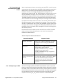
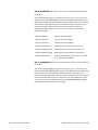
2-3-1. Terminology
Basic Hot
Swap
Hardware connection is automatic but the software
connection and failover process is manual.
Full Hot Swap
Hardware connection is automatic, software connection is
automatic, but the failover process is manual.
HA Hot Swap
Hardware connection is automatic, software connection is
automatic, and the failover process is automatic as well.
See the hardware-specific documentation of your Solaris system for details of
its System Configuration Administration support.
2-3-2. RCM overview
The Reconfiguration Coordination Manager (RCM) is the framework that
manages the dynamic removal of system components. SBE HighWire
software packages supply a RCM script for releasing a board's daemon and
control device in an orderly manner. Applications using HighWire resources
must release their own resources during dynamic removal of HighWire
components. The RCM feature was added within the Solaris 8 4/01 release
and is also available on Solaris 9.
RCM commands are invoked only for the resources whose subsystems
participate within the RCM framework. Currently, not all Solaris subsystems
participate within this framework.
(System Ref: rcmscript(4), highwire.rcm (1M))
2-3-3. hw_daemon monitoring of
hardware status
The hw_daemon process continually monitors board availability as part of its
Hot Swap support. Upon board removal, re-insertion, and configuration, the
daemon will restart the SBE HighWire adapter without further administration
intervention.
(System Ref: hw_daemon(1M))
HighWire MTP-2 - 1.2, September 4, 2002
Hot Plug Overview
13
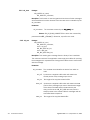
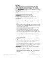
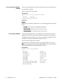
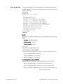
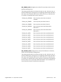
2-3-4. Daemon assignment
The SBE HighWire family of products operates under control of a daemon that
monitors status and controls access. The daemon is called wspd. There is a
separate wspd daemon for each HighWire adapter in the system.
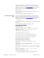
The Process ID of the daemon associated with a particular board is available
through the hwinfo command.
Example:
hwinfo -i 1
returns information about board 1.
Below is a sample entry.
*** HighWire Information for Board #1 ***
Device Type
: HW400c/R
Device S/N
: 90528
Device Info
: Brdno= 1 Bus= 3 Slot= 4 irq= 0 addr= c000000
Device Status : 1 of 130 queues open, 0 closes pending
Control Device : /dev/hw1_ctl
Control Link
: /devices/pci@1f,0/pci@1/pci@1/pci1176,600@e:1,ctl,type1
Control PID
: 140
Driver Release : SBE HighWire Driver, Version SOL6_HWMTP_GA_1_0 (Tue Aug 27 17:31:58 PDT 2002)
Driver Intrface: @(#) HMQ interface 2.1.4
PDM Release
: $Release: HW400_HWMTP2_FOR_SOL_GA_1_0, Copyright (c) 2002 SBE, Inc.$
VXBOOT Release : $Release: VXBOOT_400_1_1,
Copyright (c) 2001 SBE, Inc.$
Thus, board number 1 (Brdno) is in Slot 4 (Slot) under control of the wspd
whose Control Process ID (Control PID) is 140.
Note: There is no correlation between the Board instance (Brdno) number and
the board's slot number. The instance number is assigned according to the
sequence in which boards are initially discovered by the Solaris operating
system. However, the assignment of instance number to slot number can be
administered via the system's /etc/path_to_inst file. See the section within
wsp(7d) for an example.
(System Ref: hwinfo(1M))
2-3-5. Configure a board for basic
hot swap
Certain Solaris servers support basic hot swap by default. This means that if a
board is newly inserted, you must manually activate the I/O slot using the
cfgadm command after the board has been inserted.
Refer to your specific system's documentation for the correct configuration
procedure. SBE HighWire adapters adhere to the standard PCI HotSwap
hardware architecture.
Once a board is powered up and configured into the system, restarting the
board's software occurs automatically via the package's hw_daemon.
2-3-6. Remove a basic hot swap
enabled board
14
Software Installation and Removal
Certain Solaris servers support basic hot swap by default. This means that if a
board becomes faulty and needs replacing, you must manually deactivate the I/O
slot using the cfgadm command before you can remove the board, and then
manually reactivate the I/O slot after replacing the board. To successfully remove
a board, you must also terminate any applications or daemons currently using a
board's devices.
HighWire MTP-2 - 1.2, September 4, 2002
Certain systems may require manual termination of the board's controlling
daemon. Locate the board's daemon process number (Control PID) using the
HighWire hwinfo command (see the Daemon Assignment section, above). Then
terminate the board's controlling daemon, using the hwcmd command.
Example: hwcmd -r 1
Refer to your specific system's documentation for the correct procedure to
unconfigure a board.
You must have SuperUser privileges to unconfigure a board.
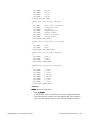
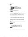
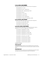
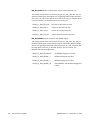
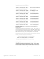
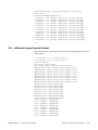
2-3-7. Sample -pkgadd- command
output
Certain systems may require manual termination of the board's controlling
daemon. Locate the board's daemon process number (Control PID) using the
HighWire hwinfo command (see the Daemon Assignment section, above). Then
terminate the board's controlling daemon, using the hwcmd command.
Example: hwcmd -r 1
Refer to your specific system's documentation for the correct procedure to unconfigure a board.
You must have SuperUser privileges to unconfigure a board.
Sample -pkgadd- Command Output
# cd /cdrom/pkg
# pkgadd -d hw8mtp_ga_1_0.sbe SBEhw
Processing package instance <SBEhw> from <cdrom/pkg/
hw8mtp_ga_1_0.sbe>
SBE HighWire, Solaris 8 Driver w/ MTP2 service.
(sparcv9) REL: SOL8_HWMTP_GA_1_0
---------------------------------| Copyright 2000-2002, SBE, Inc. |
---------------------------------This information is the confidential property
of SBE, Inc. and may not be reproduced, disclosed
or otherwise used in whole or in part except as
authorized by written permission from SBE, Inc.
## Executing checkinstall script.
## Processing package information.
## Processing system information.
## Verifying disk space requirements.
## Checking for conflicts with packages already
installed.
## Checking for setuid/setgid programs.
This package contains scripts which will be executed with
super-user
permission during the process of installing this package.
Do you want to continue with the installation of <SBEhw>
[y,n,?] y
Installing SBE HighWire, Solaris 8 Driver w/ MTP2
service. as <SBEhw>
## Executing preinstall script.
>> Cleaning up HighWire entries in devlink.tab file.
>> Cleaning up HighWire entries in minor_perm file.
HighWire MTP-2 - 1.2, September 4, 2002
Hot Plug Overview
15
## Installing part 1 of 1.
/etc/opt/SBEhw/cfg/wsp.conf
/etc/opt/SBEhw/cfg/wspcfgfile.hw400
/etc/opt/SBEhw/cfg/wspcmd.cfg
/opt/SBEhw/bin/hw_daemon
/opt/SBEhw/bin/hwcmd
/opt/SBEhw/bin/hwinfo
/opt/SBEhw/bin/hwstat
/opt/SBEhw/bin/release.sh
/opt/SBEhw/bin/wspcmd
/opt/SBEhw/bin/wspd
/opt/SBEhw/dev/devlink.tab.hw
/opt/SBEhw/pdm/pdm.hw400 <symbolic link>
/opt/SBEhw/pdm/pdm.map400 <symbolic link>
/opt/SBEhw/pdm/pdm_hwmtp.hw400
/opt/SBEhw/pdm/pdm_hwmtp.map400
/usr/kernel/drv/sparcv9/wsp
/usr/kernel/drv/wsp
/usr/kernel/drv/wsp.conf <symbolic link>
/usr/sbin/hw_daemon <symbolic link>
/usr/sbin/hwcmd <symbolic link>
/usr/sbin/hwinfo <symbolic link>
/usr/sbin/hwstat <symbolic link>
/usr/sbin/wspcmd <symbolic link>
/usr/sbin/wspd <symbolic link>
[ verifying class <Driver> ]
/etc/init.d/sbehwd
/etc/rc0.d/K50hwd <symbolic link>
/etc/rc1.d/K50hwd <symbolic link>
/etc/rc2.d/S58hwd <symbolic link>
/opt/SBEhw/bin/cbiDemo <symbolic link>
/opt/SBEhw/bin/cbiDemo_32
/opt/SBEhw/bin/cbiDemo_64
/opt/SBEhw/bin/cbiptest <symbolic link>
/opt/SBEhw/bin/cbiptest_32
/opt/SBEhw/bin/cbiptest_64
/opt/SBEhw/bin/dprDemo <symbolic link>
/opt/SBEhw/bin/dprDemo_32
/opt/SBEhw/bin/dprDemo_64
/opt/SBEhw/bin/echoDemo <symbolic link>
/opt/SBEhw/bin/echoDemo_32
/opt/SBEhw/bin/echoDemo_64
/opt/SBEhw/doc/cbiDemo.htm
/opt/SBEhw/doc/cbiptest.htm
/opt/SBEhw/doc/dprDemo.htm
/opt/SBEhw/doc/dprservice.htm
/opt/SBEhw/doc/highwire_rcm.htm
/opt/SBEhw/doc/hw_daemon.htm
/opt/SBEhw/doc/hwcmd.htm
/opt/SBEhw/doc/hwinfo.htm
/opt/SBEhw/doc/hwstat.htm
/opt/SBEhw/doc/libdpr.htm
/opt/SBEhw/doc/libsbe.htm
/opt/SBEhw/doc/manpages.htm
16
Software Installation and Removal
HighWire MTP-2 - 1.2, September 4, 2002
/opt/SBEhw/doc/sbe_BoardReady.htm
/opt/SBEhw/doc/sbe_ctlClose.htm
/opt/SBEhw/doc/sbe_ctlIssueMsg.htm
/opt/SBEhw/doc/sbe_ctlOpen.htm
/opt/SBEhw/doc/sbe_ctlRcvMsg.htm
/opt/SBEhw/doc/sbe_dataOpen.htm
/opt/SBEhw/doc/wsp.htm
/opt/SBEhw/doc/wsp_conf.htm
/opt/SBEhw/doc/wspcmd.htm
/opt/SBEhw/doc/wspcmd_cfg.htm
/opt/SBEhw/doc/wspd.htm
/opt/SBEhw/lib/libcbi.so
/opt/SBEhw/lib/libsbe.a
/opt/SBEhw/lib/libsbe.so
/opt/SBEhw/lib/sparcv9/libcbi.so
/opt/SBEhw/lib/sparcv9/libsbe.a
/opt/SBEhw/lib/sparcv9/libsbe.so
/opt/SBEhw/src/include/sbe/bi_err.h
/opt/SBEhw/src/include/sbe/cbi/cbi.h
/opt/SBEhw/src/include/sbe/cbi/cbicssif.h
/opt/SBEhw/src/include/sbe/cbi/cbim2.h
/opt/SBEhw/src/include/sbe/ctrld_if.h
/opt/SBEhw/src/include/sbe/dpr/connmgr.h
/opt/SBEhw/src/include/sbe/dpr/dpr_driver.h
/opt/SBEhw/src/include/sbe/dpr/t8102.h
/opt/SBEhw/src/include/sbe/dpr/ttsi2k32t.h
/opt/SBEhw/src/include/sbe/dprd_if.h
/opt/SBEhw/src/include/sbe/sbe_dprlib.h
/opt/SBEhw/src/include/sbe/sbe_lib.h
/opt/SBEhw/src/include/sbe/sbe_std.h
/opt/SBEhw/src/include/sbe/sbe_types.h
/opt/SBEhw/src/include/sbe/uppa.h
/opt/SBEhw/src/include/sbe/wsp_brd_prop.h
/opt/SBEhw/src/include/sbe/wsp_que_prop.h
/opt/SBEhw/src/include/sbe/wspusr.h
/opt/SBEhw/src/include/sbe/wx/a0l2l3d.h
/opt/SBEhw/src/include/sbe/wx/a0l2l3m.h
/opt/SBEhw/src/include/stdint.h
/usr/include/sbe <symbolic link>
/usr/lib/libcbi.so <symbolic link>
/usr/lib/libsbe.a <symbolic link>
/usr/lib/libsbe.so <symbolic link>
/usr/lib/rcm/scripts/SBEI,highwire.sh
/usr/lib/sparcv9/libcbi.so <symbolic link>
/usr/lib/sparcv9/libsbe.a <symbolic link>
/usr/lib/sparcv9/libsbe.so <symbolic link>
/usr/share/man/man1m/highwire_rcm.1m
/usr/share/man/man1m/hw_daemon.1m
/usr/share/man/man1m/hwcmd.1m
/usr/share/man/man1m/hwinfo.1m
/usr/share/man/man1m/hwstat.1m
/usr/share/man/man1m/wspcmd.1m
/usr/share/man/man1m/wspd.1m
/usr/share/man/man3/libsbe.3
HighWire MTP-2 - 1.2, September 4, 2002
Hot Plug Overview
17
/usr/share/man/man3x/sbe_BoardReady.3x
/usr/share/man/man3x/sbe_ctlClose.3x
/usr/share/man/man3x/sbe_ctlIssueMsg.3x
/usr/share/man/man3x/sbe_ctlOpen.3x
/usr/share/man/man3x/sbe_ctlRcvMsg.3x
/usr/share/man/man3x/sbe_dataOpen.3x
/usr/share/man/man4/wsp.conf.4
/usr/share/man/man4/wspcmd.cfg.4
/usr/share/man/man6/cbiDemo.6
/usr/share/man/man6/cbiptest.6
/usr/share/man/man6/dprDemo.6
/usr/share/man/man7d/wsp.7d
/usr/share/man/sman3sbe/libdpr.3sbe
/usr/share/man/sman3sbe/sbe_dprClose.3sbe
/usr/share/man/sman3sbe/sbe_dprConfigDefault.3sbe
/usr/share/man/sman3sbe/sbe_dprConnectionReport.3sbe
/usr/share/man/sman3sbe/sbe_dprHighwayReport.3sbe
/usr/share/man/sman3sbe/sbe_dprIoctl.3sbe
/usr/share/man/sman3sbe/sbe_dprOpen.3sbe
/usr/share/man/sman3sbe/sbe_dprPrint.3sbe
/usr/share/man/sman3sbe/sbe_dprRead.3sbe
/usr/share/man/sman3sbe/sbe_dprWrite.3sbe
/usr/share/man/sman7d/dprservice.7d
[ verifying class <System> ]
/opt/SBEhw/src/cbi_demo/Makefile.gnu
/opt/SBEhw/src/cbi_demo/Makefile.sunw
/opt/SBEhw/src/cbi_demo/cbiDemo.c
/opt/SBEhw/src/cbi_demo/makecom
/opt/SBEhw/src/cbi_demo/sbe/cbi/cbiDemo.h
/opt/SBEhw/src/cbi_demo/sbeRelease.c
/opt/SBEhw/src/cbiptest/Makefile.gnu
/opt/SBEhw/src/cbiptest/Makefile.sunw
/opt/SBEhw/src/cbiptest/cbilib/cbiapi.c
/opt/SBEhw/src/cbiptest/cbilib/cbihandl.c
/opt/SBEhw/src/cbiptest/cbilib/cbiint.h
/opt/SBEhw/src/cbiptest/cbilib/cbimon.c
/opt/SBEhw/src/cbiptest/cbilib/cbioffst.c
/opt/SBEhw/src/cbiptest/cbilib/cbitrace.c
/opt/SBEhw/src/cbiptest/cbilib/sbeRelease.c
/opt/SBEhw/src/cbiptest/cbiptest/cbipmake.c
/opt/SBEhw/src/cbiptest/cbiptest/cbiprecv.c
/opt/SBEhw/src/cbiptest/cbiptest/cbipsend.c
/opt/SBEhw/src/cbiptest/cbiptest/cbiptest.c
/opt/SBEhw/src/cbiptest/cbiptest/cbiptest.h
/opt/SBEhw/src/cbiptest/cbiptest/sbeRelease.c
/opt/SBEhw/src/cbiptest/makecom
/opt/SBEhw/src/dpr_demo/Makefile
/opt/SBEhw/src/dpr_demo/dprDemo.c
/opt/SBEhw/src/dpr_demo/dprDemo.h
/opt/SBEhw/src/dpr_demo/dprMain.c
/opt/SBEhw/src/dpr_demo/makecom
/opt/SBEhw/src/dpr_demo/sbeRelease.c
/opt/SBEhw/src/echo_demo/Makefile
/opt/SBEhw/src/echo_demo/echoDemo.c
18
Software Installation and Removal
HighWire MTP-2 - 1.2, September 4, 2002
/opt/SBEhw/src/echo_demo/makecom
/opt/SBEhw/src/echo_demo/sbeRelease.c
[ verifying class <src> ]
/opt/SBEhw/bin/doadb
/opt/SBEhw/bin/wspb32
/opt/SBEhw/bin/wspb64
/opt/SBEhw/lib/adb/alloc_ctl
/opt/SBEhw/lib/adb/alloc_page
/opt/SBEhw/lib/adb/bi_q_status_s
/opt/SBEhw/lib/adb/bi_s
/opt/SBEhw/lib/adb/board_queue
/opt/SBEhw/lib/adb/commem_ctl
/opt/SBEhw/lib/adb/hmq_ctl
/opt/SBEhw/lib/adb/hmq_msg
/opt/SBEhw/lib/adb/hmqbi
/opt/SBEhw/lib/adb/host_queue
/opt/SBEhw/lib/adb/sbehw_board_prop
/opt/SBEhw/lib/adb/sbehw_hmqstats_s
/opt/SBEhw/lib/adb/sbehw_queue_prop
/opt/SBEhw/lib/adb/sparcv9/alloc_ctl
/opt/SBEhw/lib/adb/sparcv9/alloc_page
/opt/SBEhw/lib/adb/sparcv9/bi_q_status_s
/opt/SBEhw/lib/adb/sparcv9/bi_s
/opt/SBEhw/lib/adb/sparcv9/board_queue
/opt/SBEhw/lib/adb/sparcv9/commem_ctl
/opt/SBEhw/lib/adb/sparcv9/hmq_ctl
/opt/SBEhw/lib/adb/sparcv9/hmq_msg
/opt/SBEhw/lib/adb/sparcv9/hmqbi
/opt/SBEhw/lib/adb/sparcv9/host_queue
/opt/SBEhw/lib/adb/sparcv9/sbehw_board_prop
/opt/SBEhw/lib/adb/sparcv9/sbehw_hmqstats_s
/opt/SBEhw/lib/adb/sparcv9/sbehw_queue_prop
/opt/SBEhw/lib/adb/sparcv9/stage_ctl
/opt/SBEhw/lib/adb/sparcv9/wqtab
/opt/SBEhw/lib/adb/sparcv9/wspdrvstats_t
/opt/SBEhw/lib/adb/sparcv9/wspstate
/opt/SBEhw/lib/adb/stage_ctl
/opt/SBEhw/lib/adb/wqtab
/opt/SBEhw/lib/adb/wspdrvstats_t
/opt/SBEhw/lib/adb/wspstate
[ verifying class <debug> ]
## Executing postinstall script.
>> Notify RCM daemon to invoke script registration.
>> Adding HighWire entries into minor_perm file.
>> Adding HighWire entries into devlink.tab file.
>> Adding HighWire man-page sections to configuration
file.
>> Adding HighWire Device Driver into system.
/etc/rc2.d/S58hwd: Starting HighWire Master Control
Daemon.
Installation of <SBEhw> was successful.
#
HighWire #0 slot 5: HW400c/F+ entering data/signal
acquisition mode.
HighWire MTP-2 - 1.2, September 4, 2002
Hot Plug Overview
19
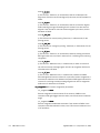
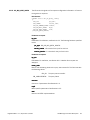
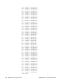
2-3-8. Sample -pkgrm- command
output
# pkgrm SBEhw
The following package is currently installed:
SBEhw
SBE HighWire, Solaris 8 Driver w/ MTP2 service.
(sparcv9) REL: SOL8_HWMTP_GA_1_0
Do you want to remove this package? y
## Removing installed package instance <SBEhw>
This package contains scripts which will be executed with superuser
permission during the process of removing this package.
Do you want to continue with the removal of this package
[y,n,?,q] y
## Verifying package dependencies.
## Processing package information.
## Executing preremove script.
>> Stopping HighWire Daemon process.
/etc/init.d/sbehwd: Stopping HighWire Master Control Daemon
(pid 412)
/etc/init.d/sbehwd: Resetting the following HighWire boards: 0.
>> Removing temporary log and socket files.
## Removing pathnames in class <debug>
/opt/SBEhw/lib/adb/wspstate
/opt/SBEhw/lib/adb/wspdrvstats_t
/opt/SBEhw/lib/adb/wqtab
/opt/SBEhw/lib/adb/stage_ctl
/opt/SBEhw/lib/adb/sparcv9/wspstate
/opt/SBEhw/lib/adb/sparcv9/wspdrvstats_t
/opt/SBEhw/lib/adb/sparcv9/wqtab
/opt/SBEhw/lib/adb/sparcv9/stage_ctl
/opt/SBEhw/lib/adb/sparcv9/sbehw_queue_prop
/opt/SBEhw/lib/adb/sparcv9/sbehw_hmqstats_s
/opt/SBEhw/lib/adb/sparcv9/sbehw_board_prop
/opt/SBEhw/lib/adb/sparcv9/host_queue
/opt/SBEhw/lib/adb/sparcv9/hmqbi
/opt/SBEhw/lib/adb/sparcv9/hmq_msg
/opt/SBEhw/lib/adb/sparcv9/hmq_ctl
/opt/SBEhw/lib/adb/sparcv9/commem_ctl
/opt/SBEhw/lib/adb/sparcv9/board_queue
/opt/SBEhw/lib/adb/sparcv9/bi_s
/opt/SBEhw/lib/adb/sparcv9/bi_q_status_s
/opt/SBEhw/lib/adb/sparcv9/alloc_page
/opt/SBEhw/lib/adb/sparcv9/alloc_ctl
/opt/SBEhw/lib/adb/sparcv9
/opt/SBEhw/lib/adb/sbehw_queue_prop
/opt/SBEhw/lib/adb/sbehw_hmqstats_s
/opt/SBEhw/lib/adb/sbehw_board_prop
/opt/SBEhw/lib/adb/host_queue
/opt/SBEhw/lib/adb/hmqbi
/opt/SBEhw/lib/adb/hmq_msg
/opt/SBEhw/lib/adb/hmq_ctl
20
Software Installation and Removal
HighWire MTP-2 - 1.2, September 4, 2002
/opt/SBEhw/lib/adb/commem_ctl
/opt/SBEhw/lib/adb/board_queue
/opt/SBEhw/lib/adb/bi_s
/opt/SBEhw/lib/adb/bi_q_status_s
/opt/SBEhw/lib/adb/alloc_page
/opt/SBEhw/lib/adb/alloc_ctl
/opt/SBEhw/lib/adb
/opt/SBEhw/bin/wspb64
/opt/SBEhw/bin/wspb32
/opt/SBEhw/bin/doadb
## Removing pathnames in class <src>
/opt/SBEhw/src/echo_demo/sbeRelease.c
/opt/SBEhw/src/echo_demo/makecom
/opt/SBEhw/src/echo_demo/echoDemo.c
/opt/SBEhw/src/echo_demo/Makefile
/opt/SBEhw/src/echo_demo
/opt/SBEhw/src/dpr_demo/sbeRelease.c
/opt/SBEhw/src/dpr_demo/makecom
/opt/SBEhw/src/dpr_demo/dprMain.c
/opt/SBEhw/src/dpr_demo/dprDemo.h
/opt/SBEhw/src/dpr_demo/dprDemo.c
/opt/SBEhw/src/dpr_demo/Makefile
/opt/SBEhw/src/dpr_demo
/opt/SBEhw/src/cbiptest/makecom
/opt/SBEhw/src/cbiptest/include
/opt/SBEhw/src/cbiptest/cbiptest/sbeRelease.c
/opt/SBEhw/src/cbiptest/cbiptest/cbiptest.h
/opt/SBEhw/src/cbiptest/cbiptest/cbiptest.c
/opt/SBEhw/src/cbiptest/cbiptest/cbipsend.c
/opt/SBEhw/src/cbiptest/cbiptest/cbiprecv.c
/opt/SBEhw/src/cbiptest/cbiptest/cbipmake.c
/opt/SBEhw/src/cbiptest/cbiptest
/opt/SBEhw/src/cbiptest/cbilib/sbeRelease.c
/opt/SBEhw/src/cbiptest/cbilib/cbitrace.c
/opt/SBEhw/src/cbiptest/cbilib/cbioffst.c
/opt/SBEhw/src/cbiptest/cbilib/cbimon.c
/opt/SBEhw/src/cbiptest/cbilib/cbiint.h
/opt/SBEhw/src/cbiptest/cbilib/cbihandl.c
/opt/SBEhw/src/cbiptest/cbilib/cbiapi.c
/opt/SBEhw/src/cbiptest/cbilib
/opt/SBEhw/src/cbiptest/Makefile.sunw
/opt/SBEhw/src/cbiptest/Makefile.gnu
/opt/SBEhw/src/cbiptest
/opt/SBEhw/src/cbi_demo/sbeRelease.c
/opt/SBEhw/src/cbi_demo/sbe/cbi/cbiDemo.h
/opt/SBEhw/src/cbi_demo/sbe/cbi
/opt/SBEhw/src/cbi_demo/sbe
/opt/SBEhw/src/cbi_demo/makecom
/opt/SBEhw/src/cbi_demo/cbiDemo.c
/opt/SBEhw/src/cbi_demo/Makefile.sunw
/opt/SBEhw/src/cbi_demo/Makefile.gnu
/opt/SBEhw/src/cbi_demo
## Removing pathnames in class <System>
/usr/share/man/sman7d/dprservice.7d
HighWire MTP-2 - 1.2, September 4, 2002
Hot Plug Overview
21
/usr/share/man/sman3sbe/sbe_dprWrite.3sbe
/usr/share/man/sman3sbe/sbe_dprRead.3sbe
/usr/share/man/sman3sbe/sbe_dprPrint.3sbe
/usr/share/man/sman3sbe/sbe_dprOpen.3sbe
/usr/share/man/sman3sbe/sbe_dprIoctl.3sbe
/usr/share/man/sman3sbe/sbe_dprHighwayReport.3sbe
/usr/share/man/sman3sbe/sbe_dprConnectionReport.3sbe
/usr/share/man/sman3sbe/sbe_dprConfigDefault.3sbe
/usr/share/man/sman3sbe/sbe_dprClose.3sbe
/usr/share/man/sman3sbe/libdpr.3sbe
/usr/share/man/sman3sbe
/usr/share/man/man7d/wsp.7d
/usr/share/man/man6/dprDemo.6
/usr/share/man/man6/cbiptest.6
/usr/share/man/man6/cbiDemo.6
/usr/share/man/man4/wspcmd.cfg.4
/usr/share/man/man4/wsp.conf.4
/usr/share/man/man3x/sbe_dataOpen.3x
/usr/share/man/man3x/sbe_ctlRcvMsg.3x
/usr/share/man/man3x/sbe_ctlOpen.3x
/usr/share/man/man3x/sbe_ctlIssueMsg.3x
/usr/share/man/man3x/sbe_ctlClose.3x
/usr/share/man/man3x/sbe_BoardReady.3x
/usr/share/man/man3/libsbe.3
/usr/share/man/man1m/wspd.1m
/usr/share/man/man1m/wspcmd.1m
/usr/share/man/man1m/hwstat.1m
/usr/share/man/man1m/hwinfo.1m
/usr/share/man/man1m/hwcmd.1m
/usr/share/man/man1m/hw_daemon.1m
/usr/share/man/man1m/highwire_rcm.1m
/usr/lib/sparcv9/libsbe.so
/usr/lib/sparcv9/libsbe.a
/usr/lib/sparcv9/libcbi.so
/usr/lib/rcm/scripts/SBEI,highwire.sh
/usr/lib/libsbe.so
/usr/lib/libsbe.a
/usr/lib/libcbi.so
/usr/include/sbe
/opt/SBEhw/src/include/stdint.h
/opt/SBEhw/src/include/sbe/wx/a0l2l3m.h
/opt/SBEhw/src/include/sbe/wx/a0l2l3d.h
/opt/SBEhw/src/include/sbe/wx
/opt/SBEhw/src/include/sbe/wspusr.h
/opt/SBEhw/src/include/sbe/wsp_que_prop.h
/opt/SBEhw/src/include/sbe/wsp_brd_prop.h
/opt/SBEhw/src/include/sbe/uppa.h
/opt/SBEhw/src/include/sbe/sbe_types.h
/opt/SBEhw/src/include/sbe/sbe_std.h
/opt/SBEhw/src/include/sbe/sbe_lib.h
/opt/SBEhw/src/include/sbe/sbe_dprlib.h
/opt/SBEhw/src/include/sbe/dprd_if.h
/opt/SBEhw/src/include/sbe/dpr/ttsi2k32t.h
/opt/SBEhw/src/include/sbe/dpr/t8102.h
22
Software Installation and Removal
HighWire MTP-2 - 1.2, September 4, 2002
/opt/SBEhw/src/include/sbe/dpr/dpr_driver.h
/opt/SBEhw/src/include/sbe/dpr/connmgr.h
/opt/SBEhw/src/include/sbe/dpr
/opt/SBEhw/src/include/sbe/ctrld_if.h
/opt/SBEhw/src/include/sbe/cbi/cbim2.h
/opt/SBEhw/src/include/sbe/cbi/cbicssif.h
/opt/SBEhw/src/include/sbe/cbi/cbi.h
/opt/SBEhw/src/include/sbe/cbi
/opt/SBEhw/src/include/sbe/bi_err.h
/opt/SBEhw/src/include/sbe
/opt/SBEhw/src/include
/opt/SBEhw/src
/opt/SBEhw/lib/sparcv9/libsbe.so
/opt/SBEhw/lib/sparcv9/libsbe.a
/opt/SBEhw/lib/sparcv9/libcbi.so
/opt/SBEhw/lib/sparcv9
/opt/SBEhw/lib/libsbe.so
/opt/SBEhw/lib/libsbe.a
/opt/SBEhw/lib/libcbi.so
/opt/SBEhw/lib
/opt/SBEhw/doc/wspd.htm
/opt/SBEhw/doc/wspcmd_cfg.htm
/opt/SBEhw/doc/wspcmd.htm
/opt/SBEhw/doc/wsp_conf.htm
/opt/SBEhw/doc/wsp.htm
/opt/SBEhw/doc/sbe_dataOpen.htm
/opt/SBEhw/doc/sbe_ctlRcvMsg.htm
/opt/SBEhw/doc/sbe_ctlOpen.htm
/opt/SBEhw/doc/sbe_ctlIssueMsg.htm
/opt/SBEhw/doc/sbe_ctlClose.htm
/opt/SBEhw/doc/sbe_BoardReady.htm
/opt/SBEhw/doc/manpages.htm
/opt/SBEhw/doc/libsbe.htm
/opt/SBEhw/doc/libdpr.htm
/opt/SBEhw/doc/hwstat.htm
/opt/SBEhw/doc/hwinfo.htm
/opt/SBEhw/doc/hwcmd.htm
/opt/SBEhw/doc/hw_daemon.htm
/opt/SBEhw/doc/highwire_rcm.htm
/opt/SBEhw/doc/dprservice.htm
/opt/SBEhw/doc/dprDemo.htm
/opt/SBEhw/doc/cbiptest.htm
/opt/SBEhw/doc/cbiDemo.htm
/opt/SBEhw/doc
/opt/SBEhw/bin/echoDemo_64
/opt/SBEhw/bin/echoDemo_32
/opt/SBEhw/bin/echoDemo
/opt/SBEhw/bin/dprDemo_64
/opt/SBEhw/bin/dprDemo_32
/opt/SBEhw/bin/dprDemo
/opt/SBEhw/bin/cbiptest_64
/opt/SBEhw/bin/cbiptest_32
/opt/SBEhw/bin/cbiptest
/opt/SBEhw/bin/cbiDemo_64
HighWire MTP-2 - 1.2, September 4, 2002
Hot Plug Overview
23
/opt/SBEhw/bin/cbiDemo_32
/opt/SBEhw/bin/cbiDemo
/opt/SBEhw <non-empty directory not removed>
/etc/rc2.d/S58hwd
/etc/rc1.d/K50hwd
/etc/rc0.d/K50hwd
/etc/init.d/sbehwd
/init.d/sbehwd
## Removing pathnames in class <Driver>
/usr/sbin/wspd
/usr/sbin/wspcmd
/usr/sbin/hwstat
/usr/sbin/hwinfo
/usr/sbin/hwcmd
/usr/sbin/hw_daemon
/usr/kernel/drv/wsp.conf
/usr/kernel/drv/wsp
/usr/kernel/drv/sparcv9/wsp
/opt/SBEhw/pdm/pdm_hwmtp.map400
/opt/SBEhw/pdm/pdm_hwmtp.hw400
/opt/SBEhw/pdm/pdm.map400
/opt/SBEhw/pdm/pdm.hw400
/opt/SBEhw/pdm
/opt/SBEhw/dev/devlink.tab.hw
/opt/SBEhw/dev
/opt/SBEhw/bin/wspd
/opt/SBEhw/bin/wspcmd
/opt/SBEhw/bin/release.sh
/opt/SBEhw/bin/hwstat
/opt/SBEhw/bin/hwinfo
/opt/SBEhw/bin/hwcmd
/opt/SBEhw/bin/hw_daemon
/opt/SBEhw/bin
/etc/opt/SBEhw/socket
/etc/opt/SBEhw/log
/etc/opt/SBEhw/cfg/wspcmd.cfg
/etc/opt/SBEhw/cfg/wspcfgfile.hw400
/etc/opt/SBEhw/cfg/wsp.conf
/etc/opt/SBEhw/cfg
/etc/opt/SBEhw
## Executing postremove script.
>> Removing HighWire man-page sections from configuration file.
>> Notify RCM daemon to remove script registration.
>> Removing HighWire Device Driver from system.
>> Removing installed directories.
>> Cleaning up HighWire entries in minor_perm file.
>> Cleaning up HighWire entries in devlink.tab file.
>> Removing HighWire devices in /dev.
## Updating system information.
Removal of <SBEhw> was successful.
24
Software Installation and Removal
HighWire MTP-2 - 1.2, September 4, 2002
3. Introduction to HighWire-MTP2
3-1. HW400 Boards
The HighWire family of communications boards includes the HW400c for host
systems with CompactPCI interfaces and the HW400p for hosts with PCI
interfaces.
Note: The HighWire 400c/R, 400c/F, and 400p also have “Plus” versions:
HW400c/R+, HW400c/F+, and HW400p+. The difference between the
regular and Plus versions is in the Motorola processor. The regular versions
use the Motorola MPC8240; the Plus versions use the faster 8245.
3-1-1. HW400c
The HW400c is a CompactPCI (cPCI), single-slot board computer that allows a
cPCI system to communicate at T1/E1 rates with other types of systems. The
HW400c allows such communication to occur using SS7, transparent, or
HDLC protocols.
The HW400c/R and HW400c/F cards provide identical functionality, but differ
in the connectivity arrangement for the eight T1/E1 ports. For simplicity, both
boards are referred to together as HW400c.
Functional Components. Each product consists of an identical base board, but
other functional components vary as described in the sections below:
HW400c/R.
Base Board - An intelligent board that provides protocol and application
processing on data communicated between the host and the network. Its
primary components are the MPC8240 microprocessor, GlobeSpan/T.Sqware
serial communication controller (SCC), and CSU/DSU functionality for eight
T1/E1/J1 ports. These ports are located on a separate Rear Transition
Module (RTM).
Mezzanine Board (or daughter card) - The HW400c/R Mezzanine Board
contains the CSU components and magnetics to manage space
considerations.
Rear Transition Module (RTM) - The HW400c/R offers eight T1/E1/J1 ports
accessible through an RTM, which installs on the opposite side of the chassis
from the base board. The RTM also features development and debug ports.
HighWire MTP-2 - 1.2, September 4, 2002
HW400 Boards
25
HW400c/F.
Base Board - An intelligent board that provides protocol and application
processing on data communicated between the host and the network. Its
primary components are the MPC8240 microprocessor, GlobeSpan/T.Sqware
serial communication controller (SCC), and CSU/DSU functionality for eight
T1/E1/J1 ports.
Mezzanine Board (or daughter card) - The HW400c/F Mezzanine Board
contains the CSU components and magnetics to manage space
considerations, and also contains eight T1/E1/J1 ports. The ports are
arranged on the mezzanine board for front panel connectivity.
3-1-2. HW400p
The HW400p/p+ is available as a single-board or two-board set that includes
these functional components:
• 2 or 6 T1/E1 physical ports
• PCI 2.1 host interface in a long card form factor
• H.100 bus interface with 32 channel Time Slot Assigner (TSA)
• Motorola 8240/8245 on-board processor
• GlobeSpan TS704 Edge Processor
• 10/100base-Tx Ethernet port
• Lucent TTSI2K32T Time Slot Interchanger (TSI)
26
Introduction to HighWire-MTP2
HighWire MTP-2 - 1.2, September 4, 2002
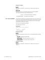
3-2. HW-MTP2 Interface Overview
The following external interfaces are present between MTP3 and HighWire
MTP2 (HW-MTP2).
• HW-MTP2 Level 2 - Level 3 Management Interface
• HW-MTP2 Level 2 - Level 3 Data Interface
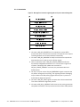
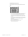
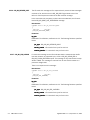
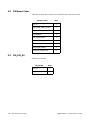
These interfaces are illustrated in Figure 3-1.
Figure 3-1 HW-MTP2 Level2 - Level 3 interfaces
MTP3
level2level 3 management interface
HW-MTP2
level2level 3 data interface
MTP1
(E1/T1)
The Level 2 - Level 3 Management and Data Interfaces are described in
Chapters 5–8 of this manual.
Throughout this manual, the term “L2” will be used to refer to any Level 2
component using these interfaces (for example, HW-MTP2 or a third party
product), and “L3” refers to any Level 3 component using these interfaces (for
example, MTP3).
Note that each instance of HW-MTP2 can be used by only one MTP3 instance
at a time. Each MTP3 instance may use multiple instances of HW-MTP2.
The signals passed over these interfaces comply with the specifications of the
ITU-T recommendation and the ANSI recommendation. Any differences in the
messages used between the two recommendations are indicated where
relevant.
HighWire MTP-2 - 1.2, September 4, 2002
HW-MTP2 Interface Overview
27
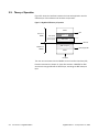
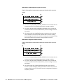
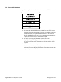
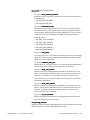
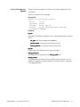
3-3. Theory of Operation
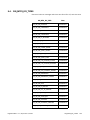
Figure 3-2 shows the interface between the host and application and the
relationships of the software and hardware components.
Figure 3-2 HighWire-MTP2 theory of operation
MTP3
Solaris on
SPARC
CBI
user space
CBI library
kernel space
WSP driver
cPCI bus
VxWorks on
HW400
SBE transport
SRTI/target CBI
MTP2
hardware
The user communicates with the HW400 via the Cross Bus Interface (CBI)
functions described in Chapter 4, Cross Bus Interface. HWMTP2 for SDK
combines the target CBI and the MTP2 layer, excluding the SBE transport
layer.
28
Introduction to HighWire-MTP2
HighWire MTP-2 - 1.2, September 4, 2002
4. Cross Bus Interface
The Cross Bus Interface (CBI) is a set of functions provided to an application
which allows that application to exchange messages with one or more entities
on each of one or more line cards. The design of this interface accomplishes
three separate aims:
• It provides a simple interface to the user.
• It is easily portable to different platforms and different underlying
transport mechanisms, subject to OS support for threads.
• It is easily extendable to support new message types.
This chapter contains:
• a functional overview (Section 4-1)
• an overview of how an application should use the provided API
(Section 4-2)
• a formal definition of the API calls (Section 4-3)
Chapter 6 describes the buffer formats.
4-1. Functional Overview
4-1-1. HWMTP2 for Solaris
For the purposes of this document, the system consists of five parts (see
Figure 3-2):
• The CBI or cross bus interface. This interface is the message-based API
provided to a user application (MTP3) running on Solaris™. The API
permits the application to exchange messages with the MTP2 on the line
card.
• The CBI library is a Solaris user space shared library which provides the
CBI API to the application on the one hand and interfaces with STREAMS
in the Solaris kernel on the other. This library is provided by SBE.
• The WSP driver resides in the Solaris kernel and routes messages
between the CBI library in user space and a reliable transport layer on the
line card. It makes use of the SBE BI and HMQ stack to communicate
across the PCI or compact PCI bus. The WSP driver is provided by SBE.
• The reliable transport layer runs on VxWorks on the PowerPC8240 chip of
the HW400 card and again makes use of the BI and HMQ stack to
communicate with the streams module on the motherboard. The reliable
transport is provided by SBE.
• The reliable transport interface provides a set of APIs (SRTI or SBE
reliable transport interface) to allow a user application running inside
VxWorks on the line card to exchange messages with an application
running on the motherboard.
The system provides the following functions:
HighWire MTP-2 - 1.2, September 4, 2002
Functional Overview
29
• Support for multiple MTP3 applications.
• Support for multiple HW400 cards.
4-1-2. HWMTP2 for SDK
For the purposes of this document, the system consists of two parts:
• The CBI library, embedded into the hwmtp2_for_sdk.o executable, is a
VxWorks-based counterpart to the CBI library for Solaris. It provides the
same message-passing interface from the target system, without the use
of STREAMS.
• The MTP2 and MTP1 layers themselves, passing target-side messages to
the HDLC controller.
4-2. Using the Cross Bus Interface
Basic interface functions include:
• cbi_initialize—initialize the CBI library (Section 4-2-1)
• cbi_terminate—finish with library (Section 4-2-1)
• cbi_open—open a connection to the line card (Section 4-2-2)
• cbi_close—close connection to the line card (Section 4-2-4)
• cbi_send—send message to an MTP2 instance (Section 4-2-5)
• cbi_recv—receive message from MTP2 instance on line card
(Section 4-2-6)
4-2-1. Initialization and termination
Before making any other calls, an application must first initialize the library by
calling cbi_initialize(). When an application has finished using the
library, it must invoke cbi_terminate() before shutting down.
4-2-2. Opening and closing a
connection to a line card
To send messages to and from a line card, an application must first open a
connection to the line card with which it wishes to communicate. This task is
accomplished with the cbi_open() call. The application provides an
appl_correlator to the library, which is returned to the application by all library
callback functions and allows the application to identify the line card
associated with those callbacks. The application supplies the cbi_correlator
returned by cbi_open() as a parameter to all subsequent calls to the
library. When an application no longer wishes to communicate with a specific
line card, it invokes cbi_close().
4-2-3. Opening and closing a subinterface
The CBI interface acts as a reliable transport over which different interfaces
may be multiplexed. Within the context of this document, a set of InterProcess Signal (IPS) messages composing a single SBE product interface (for
example the interface to MTP2) is referred to as a sub-interface. Each
sub-interface is described in its own header file.
30
Cross Bus Interface
HighWire MTP-2 - 1.2, September 4, 2002
4-2-4. Connecting to and
disconnecting from an MTP2
instance
When an application wishes to communicate with an MTP2, it must first open
a connection to the line card where the MTP2 will be located (as explained in
Section 4-2-3). It must then open the MTP2 sub-interface (defined in the
header file cbim2.h) by sending a CBI_M2_OPEN message. Once the
application has received a CBI_M2_OPEN response, it may send one or more
CBI_M2_REGISTER messages (one for each MTP2 with which it wishes to
communicate). Details of how to send a message are provided Section 4-2-5.
The MTP3 should fill in the sender_handle field of the CBI_IPS substructure
with a correlator of its own choosing. Subsequent messages received across
the interface will always contain this value in the receiver_handle field of the
CBI_IPS substructure, which is always the first member of any control buffer
structure. The MTP3 must wait for a CBI_M2_REGISTER response (after which
it must be able to receive messages) and a CBI_M2_AVAILABLE (after which
the MTP3 is free to send other MTP2 messages as it wishes according to the
SS7-defined protocol).
Disconnection may be initiated by either the MTP3 or the MTP2. The MTP2
instance will only initiate disconnection in the event of an unexpected
hardware or software failure.
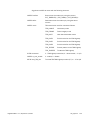
Table 4-1 Sequence of events in disconnections
Cause of disconnection
4-2-5. Sending messages to MTP2
Sequence of events
Intended disconnection
MTP3 sends a CBI_M2_UNREGISTER message to
an MTP2 and awaits a CBI_M2_UNREGISTER
response.
MTP2 failure
MTP3 receives a CBI_M2_UNAVAILABLE message
from the library. Upon receipt of a
CBI_M2_UNAVAILABLE message, the MTP3
application must respond with a
CBI_M2_UNREGISTER message. Unregistration
proceeds as normal.
Total failure (hardware or
software) of connection to
line card
MTP3 receives an error code M2_RC_IO_ERROR
to a call to cbi_send() or cbi_recv(). MTP3
then takes all necessary steps to reopen the
connection to the line card, reopen the subinterface, and reregister with all the MTP2
instances.
To send a message to MTP2, the MTP3 implementation must set up all the
fields in a control buffer using the appropriate structure defined in the header
file. MTP3 is free to use whatever sort of memory it likes (stack or otherwise)
for this buffer except that the memory must be flat. The buffer must be longer
than the defined structure by the amount returned on the CBI_M2_OPEN
response in the send_ctrl_tail_size field. If there is an associated data
HighWire MTP-2 - 1.2, September 4, 2002
Using the Cross Bus Interface
31
component for the message (CBI_M2_MSG_FOR_XMISSION), then a data
buffer must also be supplied. The data buffer is subject to the same
constraints as the control buffer, except that the additional space must be
provided both at the start and the tail of the data, and the amounts of empty
space provided are determined by the send_data_hdr_size and
send_data_tail_size fields of the CBI_M2_OPEN response.
The MTP3 then invokes the cbi_send() API to dispatch the message. The
cbi_send() API may either complete synchronously and return
CBI_RC_SYNC_COMPLETE or asynchronously complete and return
CBI_RC_ASYNC_COMPLETE. If asynchronous completion is indicated, the
application is responsible for re-transmitting the message when resources
become available.
4-2-6. Receiving messages from
MTP2
Once cbi_open() has been successfully called, an application is notified of
arriving messages via the CBI_MSG_AVAIL_CALLBACK. The CBI library invokes
this callback on a separate thread of execution. The application must then
immediately issue the cbi_recv() call to receive the message (the
application may issue this call on the same thread as it receives the callback
if it so desires, or it may issue it on an alternative thread). The cbi_recv()
call may complete with the CBI_RC_SYNC_COMPLETE return code, in which
case the message has been fully received into the application’s buffer.
Alternatively, the cbi_recv() call may complete with the
CBI_RC_ASYNC_COMPLETE return code, in which case the message was not
completely available. In this later case, the buffers do not contain a complete
message. The same buffers must be passed back into cbi_recv() the next
time the CBI library signals the application again with the
CBI_MSG_AVAIL_CALLBACK when more of the message becomes available. In
this case, the application must not alter, re-use, or free such buffers. The CBI
library may also return CBI_RC_NO_MSG, in which case the message was
destined for the library itself (in this case, however, the buffers are returned to
the application which may reuse or free them as it sees fit). Note that the
application is responsible for providing any header and/or tail bytes that it
requires.
4-2-7. Send-side flow control
(HWMTP2 for Solaris only)
When the application invokes cbi_send(), the library will normally be able
to complete the send operation synchronously and return the
CBI_RC_SYNC_COMPLETE return code. In this case, the application may free
or re-use the buffers which contained the message.
If, on the other hand, the library is unable to send a complete message
(instead sending only part or none of the message) it returns
CBI_RC_ASYNC_COMPLETE. In this case the application must re-transmit the
flow controlled message once resources become available for cross bus
transfer.
32
Cross Bus Interface
HighWire MTP-2 - 1.2, September 4, 2002
This library-messaging mechanism allows the application (or layers above it)
to impose flow control by allocating their buffers from a fixed size pool. When
messages cannot be dispatched across the interface, the number of available
buffers shrinks since the application may not free them back to the pool until
they have been sent. When the pool contains no further available buffers, the
application cannot send any more data.
Send-side flow control applies to both control and data messages in exactly
the same way.
4-2-8. Receive-side flow control
Receive-side flow control is not an integral part of the CBI interface; rather, it
is managed by IPS signals as part of the CBI_M2 sub-interface.
Receive-side flow control is simpler than send-side flow control as far as the
application is concerned. The underlying MTP2 has a fixed size buffer pool for
data messages, and messages sent to the MTP3 implementation continue to
count against the pool limit until the MTP3 informs the MTP2 that they no
longer need to be counted in this manner.
Therefore the MTP3 (or higher layers) must make a conscious decision about
when it no longer wishes a particular message to count against the MTP2
buffer pool limit. The MTP3 should then send a CBI_M2_CREDIT message
across the interface. Note that it is obviously inefficient to send one credit
message in response to every received message, so the message definition
allows MTP3 to wait until it has finished with a number of received messages
and then send just one credit message down to MTP2 granting multiple
credits. It is left to the application (which originally set the size of MTP2’s
buffer pool on the CBI_M2_UPDATE_PARMS message) to determine a suitable
interval for sending such messages, which should be a small fraction of the
size of the buffer pool itself.
HighWire MTP-2 - 1.2, September 4, 2002
Using the Cross Bus Interface
33
4-3. Basic Interface Functions and API Calls
4-3-1. cbi_initialize
Prototype.
CBI_UINT32 cbi_initialize(
CBI_SENT_CALLBACK * sent_cb,
CBI_MSG_AVAIL_CALLBACK * msg_avail_cb)
Description. This function is invoked by the user to initialize the library. It must
be invoked before any other calls are made.
Parameters
sent_cb
This callback has been deprecated [null] for Highwire MTP2 for
Solaris GA 1.0. This value is null for HWMTP2 for SDK, since all
messages are guaranteed to be delivered to the stack.
msg_avail_cb
The address of the message available callback routine that the
application supplies to allow the library to notify it when a
message is available to be received.
Returns. CBI_RC_SYNC_COMPLETE if the library has been successfully
initialized. Any other return code indicates an error.
34
Cross Bus Interface
HighWire MTP-2 - 1.2, September 4, 2002
4-3-2. cbi_terminate
Prototype.
void cbi_terminate(void)
Description. This function is invoked by the user to terminate the library. It
must be invoked when the application does not wish to make any further calls
across the interface.
Parameters. None.
Returns. void.
4-3-3. cbi_open
Prototype.
CBI_UINT32 cbi_open(
const char *name,
CBI_CORR * cbi_correlator,
CBI_CORR appl_correlator)
Description. This function is invoked by MTP3 to obtain a correlator for
subsequent communications to a line card. Note that a single correlator is
obtained once and is valid for any and all MTP2 instances that are eventually
created on the card.
Parameters.
name
cbi_correlator
appl_correlator
The driver name. This parameter uniquely identifies a
line card. Its value is the path of the streams device
corresponding to the card in question. For example,
HW0_MTP2_0 is HighWire board 0. This value is null for
HWMTP2 for SDK, since no Streams device exists.
The dress of the correlator that the application must
supply on all subsequent calls to the interface when
addressing the line card identified by the name
parameter. Returned parameter.
The correlator that the application uses to identify the
line card indicated by the name parameter. The CBI
library supplies this correlator to the application on all
callbacks associated with this line card.
Returns. CB_RC_SYNC_COMPLETE if the call is successful. Otherwise, an error
code indicating that the device does not exist, no correlators are available, or
the stream cannot be opened.
HighWire MTP-2 - 1.2, September 4, 2002
Basic Interface Functions and API Calls
35
4-3-4. cbi_close
Prototype.
CBI_UINT32 cbi_close(
CBI_CORR cbi_correlator)
Description. This function is used to signal the driver that no further messages
will be transferred in either direction to the line card which is identified by the
cbi_correlator.
Parameters.
cbi_correlator
The correlator returned by the cbi_open() call.
Returns. CBI_RC_SYNC_COMPLETE if the driver has successfully
processed the cbi_close(). Otherwise, a specific error code.
4-3-5. cbi_recv
Prototype.
CBI_UINT32 cbi_recv(
CBI_CORR cbi_correlator,
char * ctrl_buf,
CBI_BUF_SIZE ctrl_len,
char * data_buf,
CBI_BUF_SIZE data_len)
Description. This routine gets a message from the library if one is available.
This call does not block. The application must supply the buffers for receiving
the message and is responsible for freeing those buffers when it has finished
with the message.
Parameters.
cbi_correlator
36
Cross Bus Interface
The correlator that identifies the device from which to
read.
ctrl_buf
A pointer to a supplied buffer which will contain the
control portion of any message upon return.
ctrl_len
The length of the supplied control buffer.
data_buf
A pointer to a supplied buffer which will contain the data
portion of any message upon return. Note that the length
of the data in the data buffer is determined by the
data_len field in the CBI_PKT_HDR structure, which is
always present in the control buffer for messages with an
associated data component.
data_len
The length of the supplied data buffer.
HighWire MTP-2 - 1.2, September 4, 2002
Returns.
• CBI_RC_SYNC_COMPLETE if a message was successfully obtained.
• CBI_RC_ASYNC_COMPLETE if only part of a message was available. In
this case, the buffers returned to the application contain only a partial
message and should not be used. The next time the library signals that
another message is available, the same buffers should be passed back to
the library and the remainder of the message will be filled in.
• CBI_RC_NO_MSG if no message was available for the user (i.e. the
message was destined for the library itself).
• CBI_RC_INVALID if an invalid correlator was specified.
4-3-6. cbi_send
Prototype.
CBI_UINT32 cbi_send(
CBI_CORR cbi_correlator,
char * ctrl_buf,
char * data_buf)
Description. This routine supplies a message to the library for dispatch to a
line card. This call does not block.
Parameters.
cbi_correlator
The correlator identifying the line card for which the
message is destined.
ctrl_buf
A pointer to a control buffer. Note that the length of the
control buffer is determined by the ctrl_size field in the
CBI_IPS structure which is always present in the control
buffer for messages with an associated data component.
data_buf
A pointer to a data buffer. Note that the length and offset
of the data in the data buffer are determined by the
data_len and data_start fields in the CBI_PKT_HDR
structure, which is always present in the control buffer for
messages with an associated data component.
Returns.
• CBI_RC_SYNC_COMPLETE if the message was sent in a synchronous
fashion.
• CBI_RC_ASYNC_COMPLETE indicates that the message has not been
completely sent due to a flow control condition; the user must re-transmit
any flow controlled message once resources become availabe for cross
bus transfer.
• CBI_RC_IO_ERROR indicates that there is a problem with the
communication pipeline to the line card and that the user must close and
reopen the connection to reestablish communication.
• CBI_RC_INVALID indicates that the supplied correlator is invalid.
HighWire MTP-2 - 1.2, September 4, 2002
Basic Interface Functions and API Calls
37
4-3-7. CBI_MSG_AVAIL_CALLBACK
Prototype.
typedef int CBI_MSG_AVAIL_CALLBACK(
CBI_CORR appl_correlator,
CBI_LONG ips_type,
CBI_BUF_SIZE ctrl_len,
CBI_BUF_SIZE data_len)
Description. This routine informs the user application that a message is
available to be received. The user should immediately issue a cbi_recv() to
receive the message. This callback is invoked on a separate thread of
execution created by the library so the application should make sure that any
data accessed within the context of this callback is locked appropriately.
Parameters.
appl_correlator
Ips_type
The correlator used by the application to identify the line
card associated with this callback.
The type of message that the application will receive
when it next issues cbi_recv().
cbi_recv()
ctrl_len
The minimum length of the control buffer that the
application should provide on the subsequent cbi_recv().
cbi_recv()
data_len
The minimum length of the data buffer that the
application should provide on the subsequent cbi_recv().
cbi_recv()
Returns. Not used.
38
Cross Bus Interface
HighWire MTP-2 - 1.2, September 4, 2002
5. HW-MTP2 Level 2 - Level 3 Interfaces and Message
Flows
5-1. Level 2 - Level 3 Management Interface
The Level 2 - Level 3 Management Interface allows an L3 component to
manage the operation of an L2 component.
This interface allows:
• registration and unregistration of L3 with the management interface
• control and reporting of the link state
• control over the link proving mode
• local and remote processor outage
• support for link changeover
• notification of link congestion
• gathering of static and dynamic information
• monitoring of events detected by L2
This interface contains the following structures:
• CBI_M2_AVAILABLE
• CBI_M2_BSNT
• CBI_M2_BSNT_NOT_RETRIEVABL
• CBI_M2_CLEAR_RTB
• CBI_M2_CONTINUE
• CBI_M2_EMERGENCY
• CBI_M2_EMERGENCY_CEASES
• CBI_M2_EV_INDICATION
• CBI_M2_EV_REGISTER
• CBI_M2_EV_UNREGISTER
• CBI_M2_FLUSH_BUFFERS
• CBI_M2_IN_SERVICE
• CBI_M2_LINK_CONGESTED
• CBI_M2_LINK_CONGSTN_CEASED
• CBI_M2_LOC_PROCSSR_OUTAGE
• CBI_M2_LOC_PROCSSR_RECOVRD
• CBI_M2_REGISTER
• CBI_M2_UNREGISTER
• CBI_M2_OUT_OF_SERVICE
• CBI_M2_QUERY_CONFIG
HighWire MTP-2 - 1.2, September 4, 2002
Level 2 - Level 3 Management Interface
39
• CBI_M2_QUERY_STATS
• CBI_M2_QUERY_STATUS
• CBI_M2_RB_CLEARED
• CBI_M2_REM_PROCSSR_OUTAGE
• CBI_M2_REM_PROCSSR_RECOVRD
• CBI_M2_RETRIEVAL_COMPLETE
• CBI_M2_RETRIEVAL_NOT_POSS
• CBI_M2_RETRIEVED_MESSAGE
• CBI_M2_RETRIEVE_BSNT
• CBI_M2_RTB_CLEARED
• CBI_M2_START
• CBI_M2_STOP
• CBI_M2_UNAVAILABLE
• CBI_M2_UPDATE_PARMS
These structures are defined in the header file cbim2.h and described in
more detail in Chapter 6, CBI Buffer Formats.
5-2. Level 2 - Level 3 Data Interface
The Level 2 - Level 3 Data Interface defines the data transfer and control
interface between an L2 and an L3.
This interface allows:
• registration and unregistration of L2 with the data interface
• transmission and receipt of normal data packets
• requests for the retrieval of data packets which have not been
successfully transmitted.
This interface contains the following structures:
• CBI_M2_MSG_FOR_XMISSION
• CBI_M2_RECEIVED_MESSAGE
• CBI_M2_RETRIEVAL_REQ_FSNC
• CBI_M2_CLOSE
• CBI_M2_CREDIT
• CBI_M2_CREDIT_ERROR
• CBI_M2_OPEN
These structures are defined in the header file cbim2.h and described in
more detail in Chapter 6, CBI Buffer Formats.
40
HW-MTP2 Level 2 - Level 3 Interfaces and Message Flows
HighWire MTP-2 - 1.2, September 4, 2002
5-3. Message Flows
The L3 uses the Level 2 - Level 3 Interfaces to register with as many instances
of L2 as it requires, to activate and deactivate links, to access and respond to
status information, and to send and receive data.
This section describes typical flows that the L3 can use. This section is not
intended to be a full set of signal flows; other flows of signals are possible,
and some signals are not included. The signal structures are described in
detail in Chapter 6, CBI Buffer Formats.
The following abbreviations are used in the message flow diagrams for the
components of the stack:
HighWire MTP-2 - 1.2, September 4, 2002
L2
Level 2 component (for example, HW-MTP2)
L3
Level 3 component (for example, MTP3)
Message Flows
41
5-3-1. Link activation
Figure 5-1 Message flows involved in registering with an L2 process and activating a link.
L3
L2
CBI_M2_REGISTER
(1)
CBI_M2_REGISTER (rsp)
CBI_M2_AVAILABLE
(2)
CBI_M2_UPDATE_PARMS
(3)
CBI_M2_UPDATE_PARMS (rsp)
CBI_M2_EMERGENCY
(4)
CBI_M2_START
(5)
CBI_M2_IN_SERVICE
(6)
Data Transmission
1. L3 sends a CBI_M2_REGISTER to L2 to identify the correct MTP3
process with which L2 should communicate. L2 responds to the request
indicating whether the L2 stack initialized successfully.
2. L2 sends a CBI_M2_AVAILABLE to notify the L3 that it has opened the
data interface and is ready to receive further signals.
3. L3 then optionally sends a CBI_M2_UPDATE_PARMS to define the
dynamically changeable parameters in L2. L2 returns the signal as a
response, indicating if the update was successful. If
CBI_M2_UPDATE_PARMS is not issued, the parameters take their
default values.
4. L3 may or may not send a CBI_M2_EMERGENCY signal to request that
L2 perform emergency link proving. This signaling involves exchanging
only a limited set of data proving signals with the peer L2 process to
accelerate the alignment process.
5. L3 sends a CBI_M2_START signal to request that a link be established.
This action initiates the alignment process.
6. L2 sends a CBI_M2_IN_SERVICE to L3 when the link proving phase has
completed successfully. L3 may now transmit and receive data packets.
42
HW-MTP2 Level 2 - Level 3 Interfaces and Message Flows
HighWire MTP-2 - 1.2, September 4, 2002
5-3-2. Remote Processor Outage
(RPO)
RPO with ITU-T national option LPO to RPO latching.
Figure 5-2 Message flows involved when the remote end of the link suffers a processor
outage.
L3
L2
CBI_M2_REM_PROCSSR_OUTAGE
(1)
CBI_M2_LOC_PROCSSR_OUTAGE
(2)
.
.
.
CBI_M2_LOC_PROCSSR_RECOVRD
(3)
.
.
.
CBI_M2_REM_PROCSSR_RECOVRD
(4)
1. L2 issues a CBI_M2_REM_PROCSSR_OUTAGE to L3 to indicate that the
remote end of the link is signalling a processor outage condition.
2. L3 sends a CBI_M2_LOC_PROCSSR_OUTAGE to L2 and starts the
changeover for the link. Neither the BSNT nor messages are retrieved.
3. When the changeover is complete, L3 sends a
CBI_M2_LOC_PROCSSR_RECOVRD to L2.
4. At some later time, L2 sends a CBI_M2_REM_PROCESSR_RECOVRD to
notify L3 that the remote end of the link has indicated that a processor
outage condition has ended.
HighWire MTP-2 - 1.2, September 4, 2002
Message Flows
43
RPO with ITU-T or ANSI changeover in progress on recovery.
Figure 5-3 Message flows involved when the remote end of the link suffers a processor
outage.
L3
L2
CBI_M2_REM_PROCSSR_OUTAGE
(1)
CBI_M2_REM_PROCSSR_RECOVRD
(2)
CBI_M2_CONTINUE
(3)
1. L2 issues a CBI_M2_REM_PROCSSR_OUTAGE to L3 to indicate that the
remote end of the link is signalling a processor outage condition.
2. L2 sends a CBI_M2_REM_PROCESSR_RECOVRD to notify L3 that the
remote end of the link has indicated that a processor outage condition
has ended.
3. L3 sends the CBI_M2_CONTINUE signal to indicate to L2 that normal
communication has resumed and requests that L2 resume sending
data messages to its peer L2 process, including any messages pending
transmission before the processor outage condition occurred.
RPO with ITU-T changeover complete on recovery.
Figure 5-4 Message flows involved when the remote end of the link suffers a processor
outage.
L3
L2
CBI_M2_REM_PROCSSR_OUTAGE
(1)
CBI_M2_REM_PROCSSR_RECOVRD
(2)
CBI_M2_FLUSH_BUFFERS
(3)
1. L2 issues a CBI_M2_REM_PROCSSR_OUTAGE to L3 to indicate that the
remote end of the link is signalling a processor outage condition.
2. L2 sends a CBI_M2_REM_PROCESSR_RECOVRD to notify L3 that the
remote end of the link has indicated that a processor outage condition
has ended.
3. L3 sends the CBI_M2_FLUSH_BUFFERS signal to request that L2
discard any data messages pending transmission before the processor
outage condition occurred, and then resume sending data messages to
its peer L2 process.
44
HW-MTP2 Level 2 - Level 3 Interfaces and Message Flows
HighWire MTP-2 - 1.2, September 4, 2002
RPO with ANSI changeover complete on recovery.
Figure 5-5 Message flows involved when the remote end of the link suffers a processor
outage.
L3
L2
CBI_M2_REM_PROCSSR_OUTAGE
(1)
CBI_M2_REM_PROCSSR_RECOVRD
(2)
CBI_M2_FLUSH BUFFERS
(3)
CBI_M2_RTB_CLEARED
(4)
CBI_M2_RB_CLEARED
(5)
1. L2 issues a CBI_M2_REM_PROCSSR_OUTAGE to L3 to indicate that the
remote end of the link is signalling a processor outage condition.
2. L2 sends a CBI_M2_REM_PROCESSR_RECOVRD to notify L3 that the
remote end of the link has indicated that a processor outage condition
has ended.
3. L3 sends the CBI_M2_FLUSH_BUFFERS signal to instruct L2 to discard
all data messages in its retransmission buffer, transmission buffer, and
receive buffer.
4. When it has cleared the retransmission buffer, L2 sends a
CBI_M2_RTB_CLEARED signal to L3.
5. When it has cleared the receive buffer, L2 sends a
CBI_M2_RB_CLEARED signal to L3.
HighWire MTP-2 - 1.2, September 4, 2002
Message Flows
45
5-3-3. Changeover following local
detection of link failure
Figure 5-6 Message flows involved when L2 detects that a link has failed.
L3
L2
CBI_M2_OUT_OF_SERVICE
(1)
CBI_M2_RETRIEVE_BSNT
(2)
CBI_M2_BSNT
CBI_M2_RETRIEVAL_REQ_FSNC
(3)
CBI_M2_RETRIEVED_MESSAGE
CBI_M2_RETRIEVED_MESSAGE
.
.
.
CBI_M2_RETRIEVAL_COMPLETE
(4)
1. When L2 detects that the link has become unusable, it sends a
CBI_M2_OUT_OF_SERVICE signal to inform L3.
2. L3 then issues a CBI_M2_RETRIEVE_BSNT signal to request that L2
process all PDUs received from the remote L2 so far and then send a
CBI_M2_BSNT signal back to L3. The CBI_M2_BSNT signal contains the
sequence number of the last received message. If the sequence
number could not be obtained, L2 sends back a
CBI_M2_BSNT_NOT_RETRIEVABL signal.
3. L3 then sends a CBI_M2_RETRIEVAL_REQ_FSNC signal to request that
L2 return all messages that L3 has passed to it for transmission but
which have not yet been acknowledged by the partner. L2 returns the
messages in CBI_M2_RETRIEVED_MESSAGE signals.
4. When all unacknowledged messages have been returned, L2 sends a
CBI_M2_RETRIEVAL_COMPLETE signal to L3. (Even if L2 does not send
any CBI_M2_RETRIEVED_MESSAGE signals, it must return the
CBI_M2_RETRIEVAL_COMPLETE signal to L3.) If the retrieval of
unacknowledged messages is not possible, L2 sends a
CBI_M2_RETRIEVAL_NOT_POSS signal to indicate this situation to L3.
46
HW-MTP2 Level 2 - Level 3 Interfaces and Message Flows
HighWire MTP-2 - 1.2, September 4, 2002
5-3-4. Failover of MTP3 Control Part
Figure 5-7 Message flows involved after failover of the control part of MTP3 has occurred.
L3
L2
CBI_M2_REGISTER
(1)
CBI_M2_REGISTER (rsp)
CBI_M2_AVAILABLE
CBI_M2_QUERY_STATUS
(2)
CBI_M2_QUERY_STATUS (rsp)
CBI_M2_STOP
(3)
1. L3 sends a CBI_M2_REGISTER to L2 to identify the new MTP3 process
with which L2 should communicate. L2 returns the signal as a response
indicating whether the registration was successful. L2 also sends a
CBI_M2_AVAILABLE to notify the L3 that a data interface registration is
in place, and that it is ready to receive further signals.
2. On receipt of the CBI_M2_REGISTER response, L3 sends a
CBI_M2_QUERY_STATUS signal to L2 to request link status information.
L2 returns its current status information in a CBI_M2_QUERY_STATUS
response.
3. If the status information held by L3 does not match that received from
L2, L3 is responsible for synchronizing the two processes. In this
situation, L3 issues a CBI_M2_STOP signal to L2 to release the link with
the peer L2 process.
HighWire MTP-2 - 1.2, September 4, 2002
Message Flows
47
5-3-5. MTP3 Data Part failure
Figure 5-8 Message flows involved when the data part of MTP3 fails and is immediately
replaced.
L3
L2
CBI_M2_REGISTER
(1)
CBI_M2_REGISTER (rsp)
(2)
CBI_M2_LOC_PROCSSR_RECOVRD
(3)
When L2 is informed of the failure of the MTP3 Data Part, it behaves as if it
had received a Local Processor Outage signal from MTP3.
1. When L2 is informed of the replacement MTP3 Data Part, it sends a
CBI_M2_REGISTER to L3 to register with the new MTP3 data process.
2. L3 returns the signal as a response indicating whether the registration
was successful. If the registration was successful, further messages can
flow on the data interface in both directions.
3. L3 sends a CBI_M2_LOC_PROCSSR_RECOVRD to L2 to fully activate the
link again.
5-3-6. MTP3 Data Part
unavailability
Figure 5-9 Message flows involved when the data part of MTP3 fails and is not immediately replaced.
L3
L2
CBI_M2_UNAVAILABLE
(1)
CBI_M2_UNREGISTER
(2)
CBI_M2_UNREGISTER (rsp)
1. L2 sends a CBI_M2_UNAVAILABLE to notify L3 that the join to the L2-L3
data interface has permanently failed.
2. When L3 receives this signal, it issues a CBI_M2_UNREGISTER to
dissociate the L3 from the L2. L2 returns the signal as a response.
48
HW-MTP2 Level 2 - Level 3 Interfaces and Message Flows
HighWire MTP-2 - 1.2, September 4, 2002
6. CBI Buffer Formats
The header files cbi.h and cbim2.h contains all the structures that define the
format of information within the control buffers passed between the user
application and the library in the ctrl_buffer parameter of the cbi_send and
cbi_recv calls. Note that both control and data buffers consist of contiguous
memory, and that control buffers of messages which possess data parts
contain fields indicating the offset of the start of any data within its buffer and
the length of the data.
6-1. Common Header Sub-Structures
6-1-1. CBI_M2_COMMON_PARMS
This structure contains L2 common configuration parameters.
Data structure.
typedef struct cbi_m2_common_parms
{
CBI_ULONG
cong_method;
CBI_BYTE
num_cong_levels;
CBI_ULONG
cong_onset[CBI_M2_MAX_NUM_CONG_LEVELS + 1];
CBI_ULONG
cong_abate[CBI_M2_MAX_NUM_CONG_LEVELS + 1];
CBI_ULONG
cong_discard[CBI_M2_MAX_NUM_CONG_LEVELS + 1];
CBI_ULONG
t_tx_dur;
CBI_ULONG
t_ty_dur;
CBI_BYTE
initial_status;
CBI_ULONG
rcv_pool_capacity;
} CBI_M2_COMMON_PARMS;
Parameters.
cong_method
The type of transmission congestion control employed by the L2. This field can
take the following values:
HighWire MTP-2 - 1.2, September 4, 2002
CBI_CONG_CTRL_
INTERNATIONAL
Single congestion onset/abatement thresholds.
Single discard threshold.
CBI_CONG_CTRL_
NATL_WITH_PRI
Multiple (3) onset/abatement thresholds with
multiple (3) discard thresholds for discarding
messages based on priority.
CBI_CONG_CTRL_
NATL_TIMER
Multiple states for congestion. One discard
threshold. Changes to the state are determined by
a single onset threshold and the continuous
length of time the transmitter remains above that
threshold.
CBI_CONG_CTRL_
NATL_BUFFER
Multiple (3) onset/abatement thresholds. One
discard threshold.
Common Header Sub-Structures
49
num_cong_levels
The number of levels (other than zero) used for transmission congestion
control.
If cong_method is CBI_CONG_CTRL_NATL_WITH_PRI or
CBI_CONG_CTRL_NATL_BUFFER, this field denotes how many entries are
valid in the cong_onset,
cong_onset cong_abate, and possibly cong_discard arrays.
The comments on those fields assume a value of 3, for clarity.
If cong_method is CBI_CONG_CTRL_NATL_TIMER, this field denotes the
number of congestion states allowed.
If cong_method is CBI_CONG_CTRL_INTERNATIONAL, this field is ignored.
The maximum value is 3.
cong_onset
Transmission congestion onset thresholds. At the end of this list of
parameters is a section, entitled “Transmission congestion onset and
abatement thresholds”, which provides more detail on the usage of this
parameter.
cong_abate
Transmission congestion abatement thresholds. At the end of this list of
parameters is a section, entitled “Transmission congestion onset and
abatement thresholds”, which provides more detail on the usage of this
parameter.
cong_discard
Congestion discard thresholds. At the end of this list of parameters is a
section, entitled “Transmission congestion discard thresholds”, which
provides more detail on the usage of this parameter.
The following fields (t_tx_dur
t_tx_dur,
t_tx_dur t_ty_dur, and initial_status)
initial_status are only valid if
cong_method is CBI_CONG_CTRL_NATL_TIMER.
t_tx_dur
Timer Tx. If the number of messages queued on L2’s transmit and retransmit
queues exceeds the transmission congestion onset threshold for the duration
of timer Tx, the congestion status increments by 1 (up to its limit). The units of
this field are milliseconds.
t_ty_dur
Timer Ty. If the number of messages queued on L2’s transmit and retransmit
queues is lower than the transmission congestion abatement threshold for
the duration of timer Ty, the congestion status decrements by 1 (down to its
limit). The units of this field are milliseconds.
50
CBI Buffer Formats
HighWire MTP-2 - 1.2, September 4, 2002
initial_status
The initial value assigned to the transmission congestion state when the
current congestion level is 0 and the number of queued messages first
exceeds the congestion onset threshold. This value must be less than the
value of num_cong_levels.
num_cong_levels Note that the timer Tx is not used in this instance.
rcv_pool_capacity
The capacity of the buffer pool used to receive messages from the partner
level 2.
Transmission congestion onset and abatement thresholds.
If cong_method is CBI_CONG_CTRL_NATL_WITH_PRI or
CBI_CONG_CTRL_NATL_BUFFER, the valid array indexes are 1 to
num_cong_levels,
num_cong_levels representing the respective onset and abatement
thresholds.
• When the number of messages queued in L2’s transmit and retransmit
queues exceeds congestion onset threshold N, L2 sends an
M2_LINK_CONGESTED signal to L3 indicating a level of congestion equal
to N.
• When the number of queued messages falls below congestion abatement
threshold M, L2 sends an M2_LINK_CONGESTED signal to L3 indicating a
level of congestion equal to (M - 1).
• If a change in the number of messages queued causes the congestion
level to jump over more than one threshold, only one
M2_LINK_CONGESTED signal is sent. If the congestion is rising, the
congestion parameter of the M2_LINK_CONGESTED signal carries the
level of the largest onset threshold which is less than the current queue
size. If the congestion is falling, the congestion parameter carries the
level of the smallest abatement threshold that is greater than the current
queue size.
• The level N congestion abatement threshold must be greater than the
level (N-1) onset threshold.
If cong_method is CBI_CONG_CTRL_INTERNATIONAL, the valid array index is
0.
• When the number of messages queued in L2's transmit and retransmit
queues exceeds the congestion onset threshold, L2 sends an
M2_LINK_CONGESTED signal to L3 indicating a level of congestion of 1.
• When the queue length falls below the congestion abatement threshold,
L2 sends an M2_LINK_CONGSTN_CEASED signal to L3.
If cong_method is CBI_CONG_CTRL_NATL_TIMER, the valid array index is 0.
• See comments on t_tx_dur and t_ty_dur for how the onset and abatement
thresholds are used.
• When the congestion level changes, an M2_LINK_CONGESTED signal is
sent to L3.
HighWire MTP-2 - 1.2, September 4, 2002
Common Header Sub-Structures
51
Transmission congestion discard thresholds.
The array index 0 is always valid. It is the absolute discard threshold. When
the number of messages queued in L2's transmit and retransmit queues
exceeds the absolute discard threshold, L2 always discards all new messages
from L3, irrespective of the value of cong_method.
cong_method The absolute discard
threshold must be set such that if cong_method is set to
CBI_CONG_CTRL_INTERNATIONAL, the onset of congestion occurs before the
absolute discard threshold is reached. For other values of cong_method,
cong_method the
highest congestion level must be reached before the absolute discard
threshold is reached. If the absolute discard threshold is set to zero, new
messages should never be discarded.
If cong_method is CBI_CONG_CTRL_NATL_WITH_PRI, the array indexes 1 to
num_cong_levels are also valid, representing discard thresholds 1 to
num_cong_levels respectively.
• When the number of messages queued in L2's transmit and retransmit
queues exceeds congestion discard threshold N (N = 1, 2, or 3), L2
discards messages from L3 which have a message priority less than N.
• Congestion discard threshold N must be greater than congestion onset
threshold N and less than onset threshold (N+1).
• Congestion discard threshold num_cong_levels must be less than the
absolute discard threshold described above.
• A value of 0 indicates never discard the message.
6-1-2. CBI_M2_MTP2_PARMS
This structure contains MTP2-specific configuration parameters.
Data structure.
typedef struct cbi_m2_mtp2_parms
{
CBI_M2_MTP2_TIMER_PARMS
timers;
CBI_M2_MTP2_RCV_CONG_PARMS rcv_congestion;
CBI_M2_MTP2_LINK_PARMS
link_parms;
CBI_ULONG
max_proving_attempts;
CBI_M2_MTP2_AERM_PARMS
aerm;
CBI_ULONG
in_service_monitor;
CBI_M2_MTP2_SUERM_PARMS
suerm;
CBI_M2_MTP2_EIM_PARMS
eim;
} CBI_M2_MTP2_PARMS;
Substructures.
typedef struct cbi_m2_mtp2_aerm_parms
{
CBI_ULONG
aerm_tin;
CBI_ULONG
aerm_tie;
CBI_ULONG
aerm_n;
} CBI_M2_MTP2_AERM_PARMS;
typedef struct cbi_m2_mtp2_eim_parms
{
52
CBI Buffer Formats
HighWire MTP-2 - 1.2, September 4, 2002
CBI_ULONG
eim_te;
CBI_ULONG
eim_t8;
CBI_ULONG
eim_ue;
CBI_ULONG
eim_de;
} CBI_M2_MTP2_EIM_PARMS;
typedef struct cbi_m2_mtp2_link_parms
{
CBI_LONG
error_correction_method;
CBI_ULONG
transmission_rate;
CBI_ULONG
loop_delay;
CBI_ULONG
sequence_num_bits;
CBI_ULONG
send_msu_window;
CBI_ULONG
send_octet_window;
CBI_ULONG
rcv_msu_window;
} CBI_M2_MTP2_LINK_PARMS;
typedef struct cbi_m2_mtp2_rcv_cong_parms
{
CBI_ULONG
onset;
CBI_ULONG
abate;
} CBI_M2_MTP2_RCV_CONG_PARMS;
typedef struct cbi_m2_mtp2_suerm_parms
{
CBI_ULONG
suerm_t;
CBI_ULONG
suerm_d;
CBI_ULONG
suerm_n;
} CBI_M2_MTP2_SUERM_PARMS;
typedef struct cbi_m2_mtp2_timer_parms
{
CBI_ULONG
t_t1_dur;
CBI_ULONG
t_t2_dur;
CBI_ULONG
t_t3_dur;
CBI_ULONG
t_t4n_dur;
CBI_ULONG
t_t4e_dur;
CBI_ULONG
t_t5_dur;
CBI_ULONG
t_t6_dur;
CBI_ULONG
t_t7_dur;
} CBI_M2_MTP2_TIMER_PARMS;
Parameters.
timers MTP2 timer parameters.
timers.t_t1_dur
t_t1_dur
Q.703 T1 timer. Time, in milliseconds, to remain in aligned ready state
while waiting for the remote L2 to reach aligned ready. If the remote L2
does not reach aligned ready by this time, the link activation is failed.
HighWire MTP-2 - 1.2, September 4, 2002
Common Header Sub-Structures
53
timers.t_t2_dur
t_t2_dur
Q.703 T2 timer. Total time, in milliseconds, that the L2 attempts link
alignment. If the link has still not aligned by this time, the link activation is
failed.
timers.t_t3_dur
t_t3_dur
Q.703 T3 timer. Total time, in milliseconds, that the L2 remains aligned
before starting proving while waiting for the remote L2 to also become
aligned. If the remote L2 does not become aligned by this time, the link
activation is failed.
timers.t_t4n_dur
t_t4n_dur
Q.703 T4 timer for normal proving. Total time, in milliseconds, for the
proving period.
timers.t_t4e_dur
t_t4e_dur
Q.703 T4 timer for emergency proving. Total time, in milliseconds, for the
proving period.
timers.t_t5_dur
t_t5_dur
Q.703 T5 timer. Total time, in milliseconds, between sending successive
SIB signal units to the remote L2 when this L2 is suffering from receiving
congestion.
timers.t_t6_dur
t_t6_dur
Q.703 T6 timer. Maximum time, in milliseconds, for which a remote L2
can refuse to accept message signal units due to congestion before the
L2 declares the link failed.
timers.t_t7_dur
t_t7_dur
Q.703 T7 timer. Maximum time, in milliseconds, between new MSU
acknowledgments from the remote L2. In periods of receive congestion, it
becomes the maximum time between reception of SIB signal units while a
remote L2 is refusing to accept message signal units due to congestion
before the L2 declares the link failed.
rcv_congestion MTP2 receive congestion parameters.
rcv_congestion.onset
onset
Receive congestion onset threshold. If the number of MSUs in the
reception buffer gets bigger than this value, level 2 flow control measures
begin.
rcv_congestion.abate
abate
Receive congestion abatement threshold. If the number of MSUs in the
reception buffer falls below this value, level 2 flow control measures end
(if in operation).
54
CBI Buffer Formats
HighWire MTP-2 - 1.2, September 4, 2002
link_parms MTP2 link parameters.
link_parms.error_correction_method
error_correction_method
Specifies the error correction method to be used. This field can take the
following values:
• CBI_ERR_METHOD_BASIC
• CBI_ERR_METHOD_PCR
link_parms.transmission_rate
transmission_rate
Specifies the transmission rate of the link (in bits/second) and implies
the transmission type (56 and 64 kbits, or faster imply digital; 4.8 kbits
implies analog). Note that CBI_XMIT_RATE_MBITS1_5 is used to denote
1.5 Mbit/s for ITU and 1.536 Mbit/s for ANSI. This field can take the
following values:
• CBI_XMIT_RATE_KBITS4P8
• CBI_XMIT_RATE_KBITS56
• CBI_XMIT_RATE_KBITS64
• CBI_XMIT_RATE_MBITS1_5
• CBI_XMIT_RATE_MBITS2_0
link_parms.loop_delay
loop_delay
Loop delay. The time, in milliseconds, between the sending of a message
signal unit and the reception of the acknowledgement for that message
signal unit in normal operation.
link_parms.sequence_num_bits
sequence_num_bits
Number of bits in sequence number. The maximum FSN and BSN values
in an SU are one less than two to the power of this parameter.
link_parms.send_msu_window
send_msu_window
Maximum number of outgoing MSUs available for retransmission. This
value is used by both the BER and PCR error correction methods. In the
PCR case, it corresponds to the Q703 N1 parameter. A value of zero
means that there is no maximum (other than the constraint imposed by
the available FSN values).
link_parms.send_octet_window
send_octet_window
Maximum number of outgoing octets available for retransmission. This
value is used by both the BER and PCR error correction methods. In the
PCR case, it corresponds to the Q703 N2 parameter. A value of zero
means that there is no maximum.
link_parms.rcv_msu_window
rcv_msu_window
Maximum number of unprocessed incoming MSUs that may be held by
the underlying device at any one time.
max_proving_attempts
Maximum number of failed proving attempts before the link returns to the Out
of Service state. This is the Q703 AERM M parameter.
HighWire MTP-2 - 1.2, September 4, 2002
Common Header Sub-Structures
55
aerm
Alignment Error Rate Monitor (AERM) parameters (used during proving).
aerm.aerm_tin
aerm_tin
Q703 AERM Tin parameter. Normal-mode threshold of the (AERM)
counter.
aerm.aerm_tie
aerm_tie
Q703 AERM Tie parameter. Emergency-mode threshold of the (AERM)
counter.
aerm.aerm_n
aerm_n
Q703 AERM N parameter. The number of octets that causes an increment
of the AERM counter while in “octet counting” mode.
in_service_monitor
Type of monitor to use while in the In Service state. Typically this value is the
SUERM for lower speed links and the EIM for higher speed links. This field can
take the following values:
CBI_IN_SERVICE_SUERM
This value instructs the L2 to use the SUERM as its In Service error
monitor.
CBI_IN_SERVICE_EIM
This value instructs the L2 to use the EIM as its In Service error monitor.
suerm
Signal Unit Error Rate Monitor (SUERM) parameters. Ignored if the EIM is the
configured In Service monitor.
suerm.suerm_t
suerm_t
Q703 SUERM T parameter. Threshold of the SUERM counter.
suerm.suerm_d
suerm_d
Q703 SUERM D parameter. Number of octets received for each
decrement of the SUERM counter.
suerm.suerm_n
suerm_n
Q703 SUERM N parameter. The number of octets that causes an
increment of the SUERM counter while in “octet counting” mode.
eim
Errored Interval Monitor (EIM) parameters. Ignored if the SUERM is the
configured In Service monitor.
eim.eim_te
eim_te
Q703 EIM TE parameter. Threshold of the EIM counter.
eim.eim_t8
eim_t8
Q703 EIM T8 parameter. Monitoring interval, in milliseconds, between
each adjustment of the EIM counter.
56
CBI Buffer Formats
HighWire MTP-2 - 1.2, September 4, 2002
eim.eim_ue
eim_ue
Q703 EIM UE parameter. Increment of the EIM counter after each interval
in which an error occurred
eim.eim_de
eim_de
Q703 EIM DE parameter. Decrement of the EIM counter after each
interval in which no error occurred.
6-1-3. CBI_M2_SAAL_PARMS
This structure is not used in MTP2 implementations and should be zeroed.
6-1-4. CBI_PKT_HDR
This structure is a header for all messages which include control and data
parts.
Data structure.
typedef struct cbi_pkt_hdr
{
CBI_ULONG data_start;
CBI_ULONG data_len;
}
Parameters.
data_start
offset to the beginning of the data in the packet part of the IPS. This
offset allows reserved header space to be left at the beginning of the
packet.
data_len
Length of the data. This value refers to the length of the actual data itself,
not including the length of any requested header of tail bytes.
6-2. CBI Message Summary
The Level 2 - Level 3 Interface provides a set of structures for the different
messages passed between level 3 and level 2 when they do not reside in the
same N-BASE. This interface is intended primarily for use by third party MTP3
implementations but may also be used by an MTP3 to communicate with an
HW-MTP2 residing at a separate location when there is no distributed N-BASE
present.
6-2-1. Signals sent from L3 to L2
The following structures are sent from the L3 to the L2.
CBI_M2_REGISTER
CBI_M2_UNREGISTER
Identifies the associated L3 process.
Disconnects L2 from the sending L3 process and, for SAAL,
disconnects it from the ATM network.
CBI_M2_UPDATE_PARMS
Supplies dynamically changeable configuration parameters to L2.
CBI_M2_QUERY_CONFIG
Retrieves static configuration information from L2.
HighWire MTP-2 - 1.2, September 4, 2002
CBI Message Summary
57
CBI_M2_QUERY_STATS
CBI_M2_QUERY_STATUS
CBI_M2_EV_REGISTER
CBI_M2_EV_UNREGISTER
Retrieves processing status information from L2.
Directs L2 to send event notifications.
Directs L2 to stop sending notifications.
CBI_M2_LOC_PROCSSR_
OUTAGE
Notifies L2 that the L3 component has experienced a processor
outage.
CBI_M2_LOC_PROCSSR_
RECOVRD
Notifies L2 that the L3 component has recovered from a processor
outage.
CBI_M2_EMERGENCY
CBI_M2_EMERGENCY_CEASES
CBI_M2_STOP
CBI_M2_START
CBI_M2_FLUSH_BUFFERS
CBI_M2_CLEAR_RTB
CBI_M2_CONTINUE
CBI_M2_RETRIEVE_BSNT
CBI_M2_MSG_FOR_XMISSION
Requests Emergency link proving mode.
Requests Normal link proving mode.
Deactivates a link.
Requests activation of a link.
Directs the L2 to clear its transmission and retransmission buffers by
discarding any messages currently in them.
Directs the L2 to clear its retransmission buffer by discarding any
messages currently in it.
Directs the L2 to continue normal operation after a local or remote
processor outage.
Requests return of the latest received BSNT value. Either a
CBI_M2_BSNT or CBI_M2_BSNT_NOT_RETRIEVABL signal is sent in
response.
Used by the L3 to send data.
CBI_M2_RETRIEVAL_REQ_FSNC
Requests retrieval of non-acknowledged messages issued by the L3.
The response to this signal is a sequence of
CBI_M2_RETRIEVED_MESSAGE messages finishing with a
CBI_M2_RETRIEVAL_COMPLETE message.
CBI_M2_OPEN
L3 sends this message to L2 during initialization immediately after
issuing the cbi_open() call. It opens a connection to the line card. L2
returns the signal as a response.
CBI_M2_CLOSE
CBI_M2_CREDIT
58
Retrieves dynamic statistical information from L2.
CBI Buffer Formats
L3 sends this message to L2 at the end of all processing to close a
connection to a line card. It should be issued before the calls to
cbi_close() and cbi_terminate().
cbi_terminate()
L3 sends this message to L2 to release buffers for flow control
purposes on the line card. It is used to inform the L2 how many
messages have been completely processed, since the last credit
message was sent. L2 will release that number of buffers back into
its buffer pool. Hence, the L3 must ensure that it sends this message
with sufficient frequency to avoid the L2 buffer pool emptying.
HighWire MTP-2 - 1.2, September 4, 2002
6-2-2. Signals sent from L2 to L3
The following signals are sent from L2 to the L3. Note that some of these
signals are event indications, and are only sent if the L3 has registered for
receipt of them with the CBI_M2_EV_REGISTER request.
CBI_M2_AVAILABLE
Notifies the L3 that L2 initialization is
complete and that the L2 is available to send
messages.
CBI_M2_UNAVAILABLE
Notifies the L3 that the L2 is now unavailable
to send messages. The only message that the
L3 may send to the L2 after receipt of this
message is a CBI_M2_MGMT_UNREGISTER.
CBI_M2_EV_INDICATION
CBI_M2_LINK_CONGESTED
CBI_M2_LINK_CONGSTN_
CEASED
CBI_M2_IN_SERVICE
CBI_M2_OUT_OF_
SERVICE
HighWire MTP-2 - 1.2, September 4, 2002
L2 notifies the L3 of the occurrence of an
event for which it has registered.
Indicates that the transmitter is congested.
Indicates that the transmitter is no longer
congested.
Indicates the link is available for data
transmission.
Indicates the link is not available for data
transmission.
CBI_M2_RETRIEVED_
MESSAGE
Returns non-acknowledged, retrieved
messages to the L3. This signal is sent in
response to a CBI_M2_RETRIEVAL_REQ_FSNC
message.
CBI_M2_RETRIEVAL_
COMPLETE
Indicates that retrieval of non-acknowledged
messages is complete. This is the final signal
in the sequence of messages sent in response
to a CBI_M2_RETRIEVAL_REQ_FSNC
message.
CBI_M2_RETRIEVAL_
NOT_POSS
Indicates that retrieval of non-acknowledged
messages is not possible. No further
messages are sent in response to a
CBI_M2_RETRIEVAL_REQ_FSNC message.
CBI_M2_BSNT
Returns the BSNT value. This signal is sent in
response to a CBI_M2_RETRIEVE_BSNT
signal.
CBI_M2_BSNT_NOT_
RETRIEVABL
Notifies the L3 that the BSNT cannot be
retrieved. This signal is sent in response to a
CBI_M2_RETRIEVE_BSNT signal.
CBI Message Summary
59
CBI_M2_REM_
PROCSSR_OUTAGE
Notifies the L3 that the remote end of the link
is signaling a processor outage condition.
CBI_M2_REM_
PROCSSR_RECOVRD
Notifies the L3 that the remote end of the link
has signaled that a processor outage
condition has ended.
CBI_M2_RB_CLEARED
60
CBI Buffer Formats
Notifies the L3 that the receive buffer has
been cleared, as requested by the L3. ANSI
only.
CBI_M2_RTB_CLEARED
Notifies the L3 that the retransmission buffer
has been cleared, as requested by the L3.
ANSI only.
CBI_M2_RECEIVED_
MESSAGE
Used to send a received data message to the
L3.
CBI_M2_CREDIT_ERROR
This message is sent by L2 to L3 to inform the
application that it has sent an invalid credit
message.
HighWire MTP-2 - 1.2, September 4, 2002
6-3.
CBI Messages: Detailed Description
Note: The CBI messages are listed in alphabetical order.
6-3-1. CBI_M2_AVAILABLE
L2 sends this signal to the L3 at some point after responding to a
CBI_M2_REGISTER to notify the L3 that the L2 has completed the join to the
L2-L3 Data Interface and is available to receive further signals. Until the L3
has received this signal, the only signal that it may send to the L2 is a
CBI_M2_UNREGISTER.
There is no response to this message.
Data structure.
typedef struct cbi_m2_available
{
CBI_IPS
ips_hdr;
} CBI_M2_AVAILABLE;
Parameters.
ips_hdr
IPS Header. For definition, see Section 6-1-1. The following fields are specified
below:
ips_type - IPS_CBI_M2_AVAILABLE.
sender_handle - L2’s handle for the join for this link.
receiver_handle - L3’s handle for the join for this link.
6-3-2. CBI_M2_BSNT
L2 sends this message to the L3 in response to a CBI_M2_RETRIEVE_BSNT
request to pass the sequence number of the last received message. There is
no response to this message.
Data structure.
typedef struct cbi_m2_bsnt
{
CBI_IPS
ips_hdr;
CBI_ULONG
bsnt;
} CBI_M2_BSNT;
Parameters.
ips_hdr
IPS Header. For definition, see Section 6-1-1. The following fields are specified
below:
ips_type - IPS_CBI_M2_BSNT.
sender_handle - L2’s handle for the join for this link.
receiver_handle - L3’s handle for the join for this link.
bsnt
This is the sequence number of the last received PDU. It can take values in
the range 0 to 2^24 - 1.
HighWire MTP-2 - 1.2, September 4, 2002
CBI Messages: Detailed Description
61
6-3-3. CBI_M2_BSNT_NOT_RETRIE
VABL
L2 sends this message to the L3 in response to a CBI_M2_RETRIEVE_BSNT
request if it cannot retrieve the sequence number of the last received
message.
There is no response to this message.
Data structure.
typedef struct cbi_m2_bsnt_not_retrievabl
{
CBI_IPS
ips_hdr;
} CBI_M2_BSNT_NOT_RETRIEVABL;
Parameters.
ips_hdr
IPS Header. For definition, see Section 6-1-1. The following fields are specified
below:
ips_type - IPS_CBI_M2_BSNT_NOT_RETRIEVABL.
sender_handle - L2’s handle for the join for this link.
receiver_handle - L3’s handle for the join for this link.
6-3-4. CBI_M2_CLEAR_RTB
The L3 sends this message to L2 to request that it discard all data messages
in its retransmission buffer. This request is issued while in a processor outage
state.
If the major version of L2 is AWSFI, L2 sends a CBI_M2_RTB_CLEARED
message in response to this message once it clears its retransmission buffer.
Data structure.
typedef struct cbi_m2_clear_rtb
{
CBI_IPS
ips_hdr;
} CBI_M2_CLEAR_RTB;
Parameters.
ips_hdr
IPS Header. For definition, see Section 6-1-1. The following fields are specified
below:
ips_type - IPS_CBI_M2_CLEAR_RTB.
sender_handle - L3’s handle for the join for this link.
receiver_handle - L2’s handle for the join for this link.
62
CBI Buffer Formats
HighWire MTP-2 - 1.2, September 4, 2002
6-3-5. CBI_M2_CLOSE
L3 sends this message to L2 at the end of all processing to close a connection
to a line card. It should be issued before the calls cbi_close() and
cbi_terminate().
Data structure.
typedef struct cbi_m2_close
{
CBI_IPS ips_hdr;
} CBI_M2_CLOSE;
Parameters.
ips_hdr
IPS Header. For definition, see Section 6-1-1. The following fields are specified
below:
ips_type - IPS_CBI_M2_CLOSE
sender_handle - not valid
receiver_handle - not valid
6-3-6. CBI_M2_CONTINUE
The L3 sends this message to L2 following a processor outage to request that
it resume sending data messages to its peer L2 process, including sending
any messages pending transmission before the processor outage occurred.
This message is referred to as “resume” in the ANSI version of the MTP2
specification.
There is no response to this message.
Data structure.
typedef struct cbi_m2_continue
{
CBI_IPS
ips_hdr;
} CBI_M2_CONTINUE;
Parameters.
ips_hdr
IPS Header. For definition, see Section 6-1-1. The following fields are specified
below:
ips_type - IPS_CBI_M2_CONTINUE.
sender_handle - L3’s handle for the join for this link.
receiver_handle - L2’s handle for the join for this link.
HighWire MTP-2 - 1.2, September 4, 2002
CBI Messages: Detailed Description
63
6-3-7. CBI_M2_CREDIT
L3 sends this message to L2 to inform L2 that L3 has completed processing a
number of received messages. This message allows L2 to release buffers
back to the MTP2 buffer pool and acts as receive-side flow control.
L3 must ensure that it sends the CBI_M2_CREDIT message to L2 with
sufficient frequency to avoid emptying the MTP2 buffer pool.
There is no response to this message unless the number of buffers specified
is larger than the number of buffers received (see Section 6-3-8,
“CBI_M2_CREDIT_ERROR”).
Data structure.
typedef struct cbi_m2_credit
{
CBI_IPS ips_hdr;
CBI_ULONG num_msgs;
} CBI_M2_CREDIT;
Parameters.
ips_hdr
IPS header. For definition, see Section 6-1-1. The following fields are specified
below:
ips_type - IPS_CBI_M2_CREDIT.
sender_handle - L3’s handle for the join for this link.
receiver_handle - L2’s handle for the join for this link.
num_msgs
This field informs L2 how many messages have been completely processed
since the last credit message was sent. It is the number of buffers to be
released back to the buffer pool.
64
CBI Buffer Formats
HighWire MTP-2 - 1.2, September 4, 2002
6-3-8. CBI_M2_CREDIT_ERROR
This message is sent by L2 to L3 to inform the application that it has sent an
invalid credit message.
Note: This message is not intended for normal operation. It is intended to be
used as an aid to L3 development/integration in that it will be sent to the L3
when the L3 has attempted to grant credit for messages it has not received. If
the L2 receives an invalid CBI_M2_CREDIT message (num_msgs is too large),
it will send a CBI_M2_CREDIT_ERROR message back to the L3. Therefore, an
L3 under development should assert immediately upon receiving a
CBI_M2_CREDIT_ERROR message.
Data structure.
typedef struct cbi_m2_credit_error
{
CBI_IPS ips_hdr;
CBI_ULONG num_msgs;
} CBI_M2_CREDIT_ERROR;
Parameters.
ips_hdr
IPS header. For definition, see Section 6-1-1. The following fields are specified
below:
ips_type - IPS_CBI_M2_CREDIT_ERROR.
sender_handle - L3’s handle for the join for this link.
receiver_handle - L2’s handle for the join for this link.
num_msgs
Not used.
6-3-9. CBI_M2_EMERGENCY
The L3 sends this message to L2 to request that it perform emergency link
proving. This process involves exchanging a limited set of data proving signals
with the peer L2 process.
There is no response to this signal.
Data structure.
typedef struct cbi_m2_emergency
{
CBI_IPS
ips_hdr;
} CBI_M2_EMERGENCY;
Parameters.
ips_hdr
IPS Header. For definition, see Section 6-1-1. The following fields are specified
below:
ips_type - IPS_CBI_M2_EMERGENCY.
sender_handle - L3’s handle for the join for this link.
receiver_handle - L2’s handle for the join for this link.
HighWire MTP-2 - 1.2, September 4, 2002
CBI Messages: Detailed Description
65
6-3-10. CBI_M2_EMERGENCY_
CEASES
The L3 sends this message to L2 to request that it return to normal link
proving. This process involves exchanging the full set of data proving signals
with the peer L2 process.
There is no response to this signal.
Data structure.
typedef struct cbi_m2_emergency_ceases
{
CBI_IPS
ips_hdr;
} CBI_M2_EMERGENCY_CEASES;
Parameters.
ips_hdr
IPS Header. For definition, see Section 6-1-1. The following fields are specified
below:
ips_type - IPS_CBI_M2_EMERGENCY_CEASES.
sender_handle - L3’s handle for the join for this link.
receiver_handle - L2’s handle for the join for this link.
6-3-11. CBI_M2_EV_INDICATION
L2 sends this signal to L3 to indicate that an event has occurred for which the
L3 has registered. L3 does not return a response to this signal.
Data structure.
typedef struct cbi_m2_ev_indication
{
CBI_IPS
ips_hdr;
CBI_ULONG
type;
CBI_ULONG
time_stamp;
CBI_BYTE
status;
CBI_BYTE
proving_mode;
} CBI_M2_EV_INDICATION;
Parameters.
ips_hdr
IPS Header. For definition, see Section 6-1-1. The following fields are specified
below:
ips_type - IPS_CBI_M2_EV_INDICATION.
sender_handle - L2’s handle for the join for this link.
receiver_handle - L3’s handle for the join for this link.
66
CBI Buffer Formats
HighWire MTP-2 - 1.2, September 4, 2002
type
The type of the event indication; one of the following values:
CBI_M2_EV_LINK_STATUS
CBI_M2_EV_SL_FAIL_ALL
CBI_M2_EV_SL_FAIL_FIBR
_BSNR
Changes in link status.
Link failure - all reasons.
Link failure - abnormal FIBR/BSNR.
CBI_M2_EV_SL_FAIL_
NO_RSP
Link failure because the partner L2 process
failed to respond within the required time.
CBI_M2_EV_SL_FAIL_
ERROR_RATE
Link failure because the Error Monitor has
failed the link.
CBI_M2_EV_SL_FAIL_
CONG_DELAY
Link failure because L2 has been without
send credit for longer than the allowed period.
CBI_M2_EV_CONG_WITH_
DISCARD_1
The first message has been discarded at
discard level 1 after moving to this level.
CBI_M2_EV_CONG_WITH_
DISCARD_2
The first message has been discarded at
discard level 2 after moving to this level.
CBI_M2_EV_CONG_WITH_
DISCARD_3
The first message has been discarded at
discard level 3 after moving to this level.
CBI_M2_EV_ALL_EVENTS
Any of the events listed above have occurred.
time_stamp
The time stamp of the indication. It is the elapsed time in 1/100 second from
the system start time of L2.
status
The status of the link. This field is only valid if the type field has the value
CBI_M2_EV_LINK_STATUS. It can take the following values:
HighWire MTP-2 - 1.2, September 4, 2002
CBI_M2_LINK_OUT_OF_
SERVICE
No connection to partner L2.
CBI_M2_LINK_ALIGNING
L2 is establishing a connection.
CBI_M2_LINK_PROVING
A connection has been established and link
proving is in progress.
CBI_M2_LINK_ALIGNED
Local L2 has successfully proved the link and
is awaiting proving confirmation from the
partner.
CBI_M2_LINK_IN_SERVICE
Local and remote L2 processes have
successfully proved the link and data transfer
may now take place.
CBI Messages: Detailed Description
67
proving_mode
The proving mode in use by L2. This field is only valid if the type field has the
value CBI_M2_EV_LINK_STATUS and the status field has the value
CBI_M2_LINK_PROVING, CBI_M2_LINK_ALIGNED, or
CBI_M2_LINK_IN_SERVICE. This field can take the following values:
6-3-12. CBI_M2_EV_REGISTER
CBI_M2_PS_PROVING_
UNKNOWN
L2 has not yet started link proving.
CBI_M2_PS_PROVING_
NORMAL
L2 is performing Normal link proving.
CBI_M2_PS_PROVING_
EMERGENCY
L2 is performing Emergency link proving.
L3 sends this signal to L2 to register to receive notification of specific events
and state changes in the L2. Subsequent CBI_M2_EV_REGISTER signals add
to existing registrations.
L2 returns the signal as a response.
If a CBI_M2_EV_REGISTER is outstanding in the L2 when the L3 fails over, the
request should be processed to completion, but the response should be
discarded.
Data structure.
typedef struct cbi_m2_ev_register
{
CBI_IPS
ips_hdr;
CBI_ULONG
return_code;
CBI_ULONG
event_code;
} CBI_M2_EV_REGISTER;
Parameters on request.
ips_hdr
IPS Header. For definition, see Section 6-1-1. The following fields are specified
below:
ips_type - IPS_CBI_M2_EV_REGISTER.
sender_handle - L3’s handle for the join for this link.
receiver_handle - L2’s handle for the join for this link.
return_code - see “Parameters on response”
68
CBI Buffer Formats
HighWire MTP-2 - 1.2, September 4, 2002
event_code
Flags for the events for which L3 is requesting notification. This field can take
a combination of the values, combined using a bitwise OR. Values for
indication types are:
CBI_M2_EV_LINK_STATUS
CBI_M2_EV_SL_FAIL_ALL
CBI_M2_EV_SL_FAIL_FIBR
_BSNR
Changes in link status.
Link failure - all reasons.
Link failure - abnormal FIBR/BSNR.
CBI_M2_EV_SL_FAIL_
NO_RSP
Link failure because the partner L2 process
failed to respond within the required time.
CBI_M2_EV_SL_FAIL_
ERROR_RATE
Link failure because the Error Monitor has
failed the link.
CBI_M2_EV_SL_FAIL_
CONG_DELAY
Link failure because L2 has been without
send credit for longer than the allowed period.
CBI_M2_EV_CONG_WITH_
DISCARD_1
The first message has been discarded at
discard level 1 after moving to this level.
CBI_M2_EV_CONG_WITH_
DISCARD_2
The first message has been discarded at
discard level 2 after moving to this level.
CBI_M2_EV_CONG_WITH_
DISCARD_3
The first message has been discarded at
discard level 3 after moving to this level.
CBI_M2_EV_ALL_EVENTS
Any of the events listed above have occurred.
Parameters on response.
ips_hdr
IPS Header. For definition, see Section 6-1-1. Handles from request are
swapped.
return_code
Return code indicating whether the registration was successful. This field can
take the following values:
CBI_OK
The registration to receive notification of the
events specified in event_code was
successful.
CBI_RESOURCE_FAILURE
The registration failed because the L2 could
not obtain the required resources (for
example, because of a memory shortage).
CBI_UNSUCCESSFUL
HighWire MTP-2 - 1.2, September 4, 2002
The registration failed for a reason other than
resource shortage.
CBI Messages: Detailed Description
69
6-3-13. CBI_M2_EV_UNREGISTER
L3 sends this signal to L2 to unregister previous registrations for event
notification. L2 returns the signal as a response.
Data structure.
typedef struct cbi_m2_ev_unregister
{
CBI_IPS
ips_hdr;
CBI_ULONG
event_code;
} CBI_M2_EV_UNREGISTER;
Parameters on request.
ips_hdr
IPS Header. For definition, see Section 6-1-1. The following fields are specified
below:
ips_type - IPS_CBI_M2_EV_UNREGISTER.
sender_handle - L3’s handle for the join for this link.
receiver_handle - L2’s handle for the join for this link.
event_code
Flags for the events for which External Management no longer requires
notification. This field can take a combination of the values, combined using a
bitwise OR. Values for indication types are:
CBI_M2_EV_LINK_STATUS
CBI_M2_EV_SL_FAIL_ALL
CBI_M2_EV_SL_FAIL_FIBR
_BSNR
CBI Buffer Formats
Link failure - all reasons.
Link failure - abnormal FIBR/BSNR.
CBI_M2_EV_SL_FAIL_
NO_RSP
Link failure because the partner L2 process
failed to respond within the required time.
CBI_M2_EV_SL_FAIL_
ERROR_RATE
Link failure because the Error Monitor has
failed the link.
CBI_M2_EV_SL_FAIL_
CONG_DELAY
Link failure because L2 has been without
send credit for longer than the allowed period.
CBI_M2_EV_CONG_WITH_
DISCARD_1
The first message has been discarded at
discard level 1 after moving to this level.
CBI_M2_EV_CONG_WITH_
DISCARD_2
The first message has been discarded at
discard level 2 after moving to this level.
CBI_M2_EV_CONG_WITH_
DISCARD_3
The first message has been discarded at
discard level 3 after moving to this level.
CBI_M2_EV_ALL_EVENTS
70
Changes in link status.
Any of the events listed above have occurred.
HighWire MTP-2 - 1.2, September 4, 2002
Parameters on response.
ips_hdr
IPS Header. For definition, see Section 6-1-1. Handles from request are
swapped.
6-3-14. CBI_M2_FLUSH_BUFFERS
The L3 sends this message to L2 following a processor outage to request that
it discard any data messages pending transmission before the processor
outage occurred, and resume sending data messages to its peer L2 process.
This message is referred to as “clear buffers” in the ANSI version of the MTP2
spec.
There is no response to this message if the major version of the L2 is ITU.
If the major version of the L2 is ANSI, the L2 sends a CBI_M2_RTB_CLEARED
message when it has cleared the retransmission buffer, and a
CBI_M2_RB_CLEARED message when it has cleared the receive buffer. These
two response messages may be sent in either order.
Data structure.
typedef struct cbi_m2_flush_buffers
{
CBI_IPS
ips_hdr;
} CBI_M2_FLUSH_BUFFERS;
Parameters.
ips_hdr
IPS Header. For definition, see Section 6-1-1. The following fields are specified
below:
ips_type - IPS_CBI_M2_FLUSH_BUFFERS.
sender_handle - L3’s handle for the join for this link.
receiver_handle - L2’s handle for the join for this link.
HighWire MTP-2 - 1.2, September 4, 2002
CBI Messages: Detailed Description
71
6-3-15. CBI_M2_IN_SERVICE
L2 sends this message to the L3 when the link proving phase has completed
successfully. The L3 may now transmit data packets.
There is no response to this message.
Data structure.
typedef struct cbi_m2_in_service
{
CBI_IPS
ips_hdr;
} CBI_M2_IN_SERVICE;
Parameters.
ips_hdr
IPS Header. For definition, see Section 6-1-1. The following fields are specified
below:
ips_type - IPS_CBI_M2_IN_SERVICE.
sender_handle - L2’s handle for the join for this link.
receiver_handle - L3’s handle for the join for this link.
6-3-16. CBI_M2_LINK_
CONGESTED
L2 sends this message to the L3 to indicate congestion at some lower layer.
After receiving a CBI_M2_LINK_CONGESTED signal, the L3 should reduce the
rate of sending data to the L2 until it receives a
CBI_M2_LINK_CONGSTN_CEASED signal for the link.
There is no response to this message.
For multiple congestion level configuration, L2 sends just
CBI_M2_LINK_CONGESTED signals with the appropriate level of congestion.
The L3 then decides how to change the rate at which it sends data messages
to L2.
For single congestion level support, L2 alternates sending
CBI_M2_LINK_CONGESTED and CBI_M2_LINK_CONGSTN_CEASED signals.
Data structure.
typedef struct cbi_m2_link_congested
{
CBI_IPS
ips_hdr;
CBI_BYTE
cong_level;
} CBI_M2_LINK_CONGESTED;
Parameters.
ips_hdr
IPS Header. For definition, see Section 6-1-1. The following fields are specified
below:
ips_type - IPS_CBI_M2_LINK_CONGESTED.
sender_handle - L2’s handle for the join for this link.
receiver_handle - L3’s handle for the join for this link.
72
CBI Buffer Formats
HighWire MTP-2 - 1.2, September 4, 2002
cong_level
This is the current congestion level when multiple congestion levels have
been configured. Constants for the congestion level in use by L2. This field
can take the following values:
• CBI_M2_CONG_LEVEL_1
• CBI_M2_CONG_LEVEL_2
• CBI_M2_CONG_LEVEL_3
• CBI_M2_CONG_NONE
6-3-17. CBI_M2_LINK_CONGSTN_
CEASED
L2 sends this message to the L3 when a congestion condition in the lower
layers (previously reported with the CBI_M2_LINK_CONGESTED signal) is
cleared. The L3 can start increasing the rate of sending data again.
There is no response to this message.
Data structure.
typedef struct cbi_m2_link_congstn_ceased
{
CBI_IPS
ips_hdr;
} CBI_M2_LINK_CONGSTN_CEASED;
Parameters.
ips_hdr
IPS Header. For definition, see Section 6-1-1. The following fields are specified
below:
ips_type - IPS_CBI_M2_LINK_CONGESTN_CEASED.
sender_handle - L2’s handle for the join for this link.
receiver_handle - L3’s handle for the join for this link.
6-3-18. CBI_M2_LOC_PROCSSR_
OUTAGE
The L3 sends this signal to L2 to notify it that the L3 process has experienced
a processor outage.
There is no response to this signal.
Data structure.
typedef struct cbi_m2_loc_procssr_outage
{
CBI_IPS
ips_hdr;
} CBI_M2_LOC_PROCSSR_OUTAGE;
Parameters.
ips_hdr
IPS Header. For definition, see Section 6-1-1. The following fields are specified
below:
ips_type - IPS_CBI_M2_LOC_PROCSSR_OUTAGE.
sender_handle - L3’s handle for the join for this link.
receiver_handle - L2’s handle for the join for this link.
HighWire MTP-2 - 1.2, September 4, 2002
CBI Messages: Detailed Description
73
6-3-19. CBI_M2_LOC_PROCSSR_
RECOVRD
The L3 sends this signal to L2 to notify L2 that the L3 process has recovered
from a processor outage.
There is no response to this signal.
Data structure.
typedef struct cbi_m2_loc_procssr_recovrd
{
CBI_IPS
ips_hdr;
} CBI_M2_LOC_PROCSSR_RECOVRD;
Parameters.
ips_hdr
IPS Header. For definition, see Section 6-1-1. The following fields are specified
below:
ips_type - IPS_CBI_M2_LOC_PROCSSR_RECOVRD.
sender_handle - L3’s handle for the join for this link.
receiver_handle - L2’s handle for the join for this link.
6-3-20. CBI_M2_REGISTER
The L3 sends this signal to the L2 to register as a user of the link. Once the
registration response is received, the L3 must be capable of receiving other
messages across the interface. The L3 may not transmit messages across the
interface until a CBI_M2_AVAILABLE has been received.
The L2 returns the signal as a response.
Note that once this message has been sent, the application may not send
ANY further messages (even a CBI_M2_UNREGISTER) until it has received the
CBI_M2_REGISTER and CBI_M2_AVAILABLE response.
Data structure.
typedef struct cbi_m2_register
{
CBI_IPS
CBI_ULONG
CBI_PROC_ID
CBI_QUEUE_ID
CBI_ULONG
CBI_BYTE
CBI_ULONG
CBI_ULONG
CBI_M2_MTP2_REGISTER_PARMS
CBI_M2_SAAL_REGISTER_PARMS
} CBI_M2_REGISTER;
74
CBI Buffer Formats
ips_hdr;
return_code;
l3_mgmt_pid;
l3_mgmt_qid;
link_set_id;
link_slc;
l3_id;
major_variant;
mtp2_parms;
saal_parms;
HighWire MTP-2 - 1.2, September 4, 2002
Parameters on request.
ips_hdr
IPS Header. For definition, see Section 6-1-1. The following fields are specified
below:
ips_type - IPS_CBI_M2_REGISTER.
sender_handle - L3’s handle for the join for this link.
receiver_handle - L2’s handle for the join for this link.
l3_mgmt_pid
Process ID to which L2 must send all management messages for this L3,
including the CBI_M2_REGISTER response.
l3_mgmt_qid
Queue ID to which L2 must send all management messages for this L3,
including the CBI_M2_REGISTER response.
The following fields (link_set_id
link_set_id,
l3_id) are used for logging in L2
link_set_id link_slc, and l3_id
and are supplied by L3 on the CBI_M2_REGISTER signal to facilitate
coordinated logging across the SS7 system. L2 does not interpret these
values, but just supplies them on the Problem Determination Logs.
link_set_id
ID of the Link Set to which this L2 link belongs. L3 supplies this field for
logging purposes only.
link_slc
The Signalling Link Code of this link. L3 supplies this field for logging
purposes only.
l3_id
An identifier for the specific L3 process using this link. L3 supplies this field
for logging purposes only.
major_variant
Major variant option. This field can take the following values:
CBI_M2_MAJOR_VARIANT_ITU
CBI_M2_MAJOR_VARIANT_ANSI
Major variant is ITU.
Major variant is ANSI.
mtp2_parms
See Section 6-1-2.
saal_parms
This structure is not used in MTP2 implementations and should be zeroed.
HighWire MTP-2 - 1.2, September 4, 2002
CBI Messages: Detailed Description
75
Parameters on response.
ips_hdr
IPS Header. For definition, see Section 6-1-1. Handles from request are
swapped.
return_code
Return code from L2 to L3 indicating whether the L2 stack initialized
successfully. This field can take the following values:
CBI_OK
CBI_UNSUCCESSFUL
6-3-21. CBI_M2_UNREGISTER
The stack was initialized successfully.
The stack was not initialized.
The L3 sends this signal to L2 to dissociate the L3 from the L2 process. If the
L2 has a join to the L2-L3 Data Interface of the L3, it must delete it on receipt
of this signal (although it does not need to wait for that join to finish being
removed before replying to this signal).
The L2 returns the signal as a response.
This signal always succeeds.
Data structure.
typedef struct cbi_m2_unregister
{
CBI_IPS
ips_hdr;
} CBI_M2_UNREGISTER;
Parameters on request.
ips_hdr
IPS Header. For definition, see Section 6-1-1. The following fields are specified
below:
ips_type - IPS_CBI_M2_UNREGISTER.
sender_handle - L3’s handle for the join for this link.
receiver_handle - L2’s handle for the join for this link.
Parameters on response.
ips_hdr
IPS Header. For definition, see Section 6-1-1. Handles from request are
swapped.
76
CBI Buffer Formats
HighWire MTP-2 - 1.2, September 4, 2002
6-3-22. CBI_M2_MSG_FOR_
XMISSION
The L3 sends this message to the L2 to pass it a data message to be sent
over the link.
There is no response to this message.
Data structure.
typedef struct cbi_m2_msg_for_xmission
{
CBI_IPS
ips_hdr;
CBI_PKT_HDR
pkt_hdr;
CBI_ULONG
dest_pt_code_len;
CBI_BYTE
dest_pt_code[CBI_MAX_DEST_PT_CODE_LEN];
} CBI_M2_MSG_FOR_XMISSION;
Parameters.
ips_hdr
IPS Header. For definition, see Section 6-1-1. The following fields are specified
below:
ips_type - IPS_CBI_M2_MSG_FOR_XMISSION.
sender_handle - L3’s handle for the join for this link.
receiver_handle - L2’s handle for the join for this link.
pkt_hdr
Packet Header. See Section 6-1-4 for more information.
dest_pt_code_len
The number of valid characters in the dest_pt_code field.
dest_pt_code[]
The Destination Point Code for this link. MTP3 supplies this field in a form
suitable for logging as a string of characters. The sole reason for supplying it
is for logging purposes.
HighWire MTP-2 - 1.2, September 4, 2002
CBI Messages: Detailed Description
77
6-3-23. CBI_M2_OPEN
L3 sends this message to L2 during initialization, immediately after issuing
the cbi_open() call. It opens a connection to the line card. L2 returns the
signal as a response.
Data structure.
typedef struct cbi_m2_open
{
CBI_IPS
ips_hdr;
CBI_ULONG entity_index;
CBI_BYTE l1_framing[CBI_L1_MAX_FRAMERS];
CBI_BYTE l1_clocking[CBI_L1_MAX_FRAMERS];
CBI_BYTE l1_line_type[CBI_L1_MAX_FRAMERS];
CBI_BYTE l1_line_code[CBI_L1_MAX_FRAMERS];
CBI_BYTE l1_line_build_out[CBI_L1_MAX_FRAMERS];
CBI_BUF_SIZE send_ctrl_tail_size;
CBI_BUF_SIZE send_data_hdr_size;
CBI_BUF_SIZE send_data_tail_size;
CBI_ULONG return_code;
} CBI_M2_OPEN;
Parameters.
ips_hdr
IPS Header. For definition, see Section 6-1-1. The following fields are specified
below:
ips_type - IPS_CBI_M2_OPEN.
sender_handle - not valid
receiver_handle - not valid
entity_index
The entity index of the requesting L3.
l1_framing [CBI_L1_MAX_FRAMERS]
The type of physical framing for each framer on the line card. The types are:
CBI_L1_FRAMING_NONE - undefined
CBI_L1_FRAMING_E1 - E1 framing
CBI_L1_FRAMING_T1 - T1 framing
l1_clocking [CBI_L1_MAX_FRAMERS]
The type of transmit clocking for each physical framer on the line card:
CBI_L1_CLOCKING_LOOP - use recovered Rx clock as Tx clock.
CBI_L1_CLOCKING_LOCAL - drive Tx clock directly from local clock.
CBI_L1_CLOCKING_THROUGH - drive the Tx clock from the recovered Rx
clock from another port.
78
CBI Buffer Formats
HighWire MTP-2 - 1.2, September 4, 2002
l1_line_type [CBI_L1_MAX_FRAMERS]
The physical line type for each framer on the line card. The types are:
CBI_HM_DS1LF_D4 - T1/D4
CBI_HM_DS1LF_D4_MF - T1/MultiFrame
CBI_HM_DS1LF_ESF - T1 extended Super Frame
CBI_HM_DS1LF_ESF_MF
CBI_HM_DS1LF_E1 - E1/no CRC
CBI_HM_DS1LF_E1_CRC- E1/CRC
CBI_HM_DS1LF_E1_MF - E1/MultiFrame
CBI_HM_DS1LF_E1_CRC_MF - E1/MultiFrame, CRC4
l1_line_code [CBI_L1_MAX_FRAMERS]
The physical line code for each framer on the line card. The types are:
CBI_HM_DS1_PHYS_ENC_B8ZS - B8ZS
CBI_HM_DS1_PHYS_ENC_AMI - AMI
CBI_HM_DS1_PHYS_ENC_HDB3 - HDB3
l1_line_build_out [CBI_L1_MAX_FRAMERS]
The line build out for each framer on the line card. In E1, this is the line
impedance. In T1, it is the line length in feet. The types are:
CBI_HM_DS1_E1_IMPEDANCE_75_OHM
CBI_HM_DS1_E1_IMPEDANCE_120_OHM
CBI_HM_DS1_E1_IMPEDANCE_75_OHM_HIGH
CBI_HM_DS1_E1_IMPEDANCE_120_OHM_HIGH
CBI_HM_DS1_T1_LINE_LEN_0_TO_133FT
CBI_HM_DS1_T1_LINE_LEN_133_TO_266FT
CBI_HM_DS1_T1_LINE_LEN_266_TO_399FT
CBI_HM_DS1_T1_LINE_LEN_399_TO_533FT
CBI_HM_DS1_T1_LINE_LEN_533_TO_655FT
Parameters on response.
send_ctrl_tail_size
On response, this field contains the size of additional empty space that the
application must provide at the end of all control packets it passes to the CBI
library.
send_data_hdr_size
On response, this field contains the size of additional free space at the start
of all data packets that the application passes to the CBI library.
HighWire MTP-2 - 1.2, September 4, 2002
CBI Messages: Detailed Description
79
send_data_tail_size
On response, this field contains the size of additional free space at the end of
all data packets that the application passes to the CBI library.
Return code.
On response, this field indicates whether the open was successfully
processed. The following values are allowed:
CBI_OK
CBI_UNSUCCESSFUL
6-3-24. CBI_M2_OUT_OF_SERVICE
The open message succeeded.
The open message did not
succeed.
L2 sends this message to the L3 when the link fails and can no longer be
used to transmit data packets.
There is no response to this message.
Data structure.
typedef struct cbi_m2_out_of_service
{
CBI_IPS
ips_hdr;
} CBI_M2_OUT_OF_SERVICE;
Parameters.
ips_hdr
IPS Header. For definition, see Section 6-1-1. The following fields are specified
below:
ips_type - IPS_CBI_M2_OUT_OF_SERVICE.
sender_handle - L2’s handle for the join for this link.
receiver_handle - L3’s handle for the join for this link.
80
CBI Buffer Formats
HighWire MTP-2 - 1.2, September 4, 2002
6-3-25. CBI_M2_QUERY_CONFIG
The L3 sends this signal to L2 to request configuration information. L2 returns
the signal as a response.
Data structure.
typedef struct cbi_m2_query_config
{
CBI_IPS
ips_hdr;
CBI_ULONG
return_code;
CBI_M2_COMMON_PARMS common;
CBI_M2_MTP2_PARMS
mtp2;
CBI_M2_SAAL_PARMS
saal;
} CBI_M2_QUERY_CONFIG;
Parameters on request.
ips_hdr
IPS Header. For definition, see Section 6-1-1. The following fields are specified
below:
ips_type - IPS_CBI_M2_QUERY_CONFIG.
sender_handle - L3’s handle for the join for this link.
receiver_handle - L2’s handle for the join for this link.
Parameters on response.
ips_hdr
IPS Header. For definition, see Section 6-1-1. Handles from request are
swapped.
return_code
Return code indicating whether the query was successful. This field can take
the following values:
CBI_OK
CBI_UNSUCCESSFUL
The query was successful.
The query failed.
common
Common L2 parameters. See Section 6-1-1.
mtp2
MTP2 specific parameters. See Section 6-1-2.
saal
Not used in MTP2 implementations.
HighWire MTP-2 - 1.2, September 4, 2002
CBI Messages: Detailed Description
81
6-3-26. CBI_M2_QUERY_STATS
The L3 sends this signal to L2 to request the return of statistical information.
L2 returns the signal as a response.
Data structure.
typedef struct cbi_m2_query_stats
{
CBI_IPS
ips_hdr;
CBI_HANDLE
correlator;
CBI_ULONG
return_code;
CBI_BYTE
reset_stats;
CBI_M2_COMMON_STATS common;
CBI_M2_MTP2_STATS
mtp2;
CBI_M2_SAAL_STATS
saal;
} CBI_M2_QUERY_STATS;
Substructures.
typedef struct cbi_m2_common_stats
{
CBI_ULONG duration_in_service;
CBI_ULONG
num_align_failures;
CBI_ULONG
num_retrans_rqs_sent;
CBI_UINT64
num_sd_trans;
CBI_UINT64
num_sd_rcvd;
CBI_ULONG
num_cong_msgs[CBI_M2_MAX_NUM_CONG_LEVELS + 1];
CBI_ULONG
cong_duration[CBI_M2_MAX_NUM_CONG_LEVELS + 1];
CBI_ULONG
num_msgs_discarded[CBI_M2_MAX_NUM_CONG_LEVELS + 1];
CBI_ULONG
num_cong_with_discard[CBI_M2_MAX_NUM_CONG_LEVELS + 1];
CBI_UINT64 num_sd_bytes_trans;
CBI_UINT64
num_sd_bytes_retrans;
CBI_UINT64
num_sd_bytes_rcvd;
} CBI_M2_COMMON_STATS;
typedef struct cbi_m2_mtp2_stats
{
CBI_ULONG
neg_ack_rcvd;
CBI_ULONG
busy_lssu_sent;
} CBI_M2_MTP2_STATS;
typedef struct cbi_m2_saal_stats
{
/*Not used in MTP2*/
}
82
CBI Buffer Formats
HighWire MTP-2 - 1.2, September 4, 2002
Parameters on request.
ips_hdr
IPS Header. For definition, see Section 6-1-1. The following fields are specified
below:
ips_type - IPS_CBI_M2_QUERY_STATS.
sender_handle - L3’s handle for the join for this link.
receiver_handle - L2’s handle for the join for this link.
correlator
Correlator field is supplied on the request and returned on the response.
reset_stats
Indicates if and how L2 should reset any of the statistics to zero. This field can
take the following values:
CBI_YES
CBI_NO
After processing this request, L2 should set to zero all (and
only) the internal statistics whose corresponding field in
the CBI_M2_COMMON_STATS structures is non-zero. All
the fields in the CBI_M2_MTP2_STATS and
CBI_M2_SAAL_STATS structures should be reset to zero
unconditionally.
L2 should not reset any internal statistics.
Parameters on response.
ips_hdr
IPS Header. For definition, see Section 6-1-1. Handles from request are
swapped.
correlator
Correlator field is supplied on the request and returned on the response.
return_code
Return code indicating whether the query was successful. This field can take
the following values:
CBI_OK
CBI_UNSUCCESSFUL
HighWire MTP-2 - 1.2, September 4, 2002
The query was successful.
The query failed.
CBI Messages: Detailed Description
83
common
common.duration_in_service
duration_in_service
The length of time that the status of the link has been
CBI_M2_LINK_IN_SERVICE. This parameter is a cumulative count; it
applies to the total length of time that the link has been active since the
counter was last reset.
common.num_align_failures
num_align_failures
The total number of link alignment failures.
common.num_retrans_rqs_sent
num_retrans_rqs_sent
The number of sequenced data messages for which L2 had to request
retransmission.
common.num_sd_trans
num_sd_trans
The total number of sequenced data messages transmitted.
common.num_sd_rcvd
num_sd_rcvd
The total number of sequenced data messages received.
common.num_cong_msgs
num_cong_msgs
The total number of CBI_M2_LINK_CONGESTED messages which L2 has
sent to L3 for each congestion level.
If the International, single congestion level is configured, then the first
entry (index 0) contains the number of congested signals sent.
If the National option of multiple congestion levels is configured, then the
number of congested signals for congestion levels 1–3 are stored in array
indexes 1–3.
common.cong_duration
cong_duration
The total time, in seconds, that the transmitter has experienced
congestion for each congestion level that is configured. This is a
cumulative count, and includes all the individual periods of congestion for
that level.
If the International, single congestion level is configured, the duration of
congestion is stored in the first entry (index 0).
If the National option of multiple congestion levels is configured, then the
durations of congestion for levels 1–3 are stored in array indexes 1–3.
common.num_msgs_discarded
num_msgs_discarded
The total number of messages discarded because of transmission
congestion for the different congestion/discard levels (possibly just one
level).
The first entry (index 0) always holds the number of messages discarded
due to hitting the absolute discard limit.
84
CBI Buffer Formats
HighWire MTP-2 - 1.2, September 4, 2002
If the National option of multiple congestion discard levels is configured,
then the number of messages discarded for levels 1–3 are stored in array
indexes 1–3.
common.num_cong_with_discard
num_cong_with_discard
The total number of congestion events (for each congestion level) which
resulted in one or more messages being discarded.
If the International, single congestion discard level is configured, the
number of congestion events which resulted in one or more messages
being discarded is stored in the first entry (index 0).
If the National option of multiple congestion discard levels is configured,
then the number of such events for levels 1–3 are stored in array indexes
1–3.
common.num_sd_bytes_trans
num_sd_bytes_trans
The number of sequenced data bytes transmitted.
common.num_sd_bytes_retrans
num_sd_bytes_retrans
The number of sequenced data bytes retransmitted.
common.num_sd_bytes_rcvd
num_sd_bytes_rcvd
The number of sequenced data bytes received.
mtp2
MTP2 specific parameters.
mtp2.neg_ack_rcvd
neg_ack_rcvd
The total number of negative acknowledgements received.
mtp2.busy_lssu_sent
busy_lssu_sent
The total number of Busy LSSU SIBs transmitted.
saal
Not used in MTP2 implementations.
HighWire MTP-2 - 1.2, September 4, 2002
CBI Messages: Detailed Description
85
6-3-27. CBI_M2_QUERY_STATUS
The L3 sends this signal to L2 to request link status information.
L2 sends this signal in response.
Data structure.
typedef struct cbi_m2_query_status
{
CBI_IPS
ips_hdr;
CBI_BYTE
cong_level;
CBI_BYTE
link_status;
CBI_BYTE
ups;
CBI_BYTE
lpo;
CBI_BYTE
retrieval_pending;
CBI_BYTE
link_avail_status;
CBI_BYTE
update_parms_pending;
CBI_ULONG
event_code;
CBI_M2_MTP2_STATUS mtp2;
} CBI_M2_QUERY_STATUS;
Substructure.
typedef struct cbi_m2_mtp2_status
{
CBI_BYTE
rpo;
CBI_BYTE
continue_pending;
CBI_BYTE
rtb_cleared_pending;
CBI_BYTE
rb_cleared_pending;
} CBI_M2_MTP2_STATUS;
Parameters on request.
ips_hdr
IPS Header. For definition, see Section 6-1-1. The following fields are specified
below:
ips_type - IPS_CBI_M2_QUERY_STATUS.
sender_handle - L3’s handle for the join for this link.
receiver_handle - L2’s handle for the join for this link.
Parameters on response.
ips_hdr
IPS Header. For definition, see Section 6-1-1. Handles from request are
swapped.
86
CBI Buffer Formats
HighWire MTP-2 - 1.2, September 4, 2002
cong_level
The current congestion level. For single congestion thresholds, 0 means Not
Congested, and 1 means Congested. For multiple congestion levels, this field
can take values 0 - num_cong_levels (from M2_UPDATE_PARMS) inclusive.
Constants for the congestion level in use by L2. This field can take the
following values:
• CBI_M2_CONG_LEVEL_1
• CBI_M2_CONG_LEVEL_2
• CBI_M2_CONG_LEVEL_3
• CBI_M2_CONG_NONE
link_status
The link status. This field can take the following values:
• CBI_M2_LINK_ALIGNED
• CBI_M2_LINK_ALIGNING
• CBI_M2_LINK_IN_SERVICE
• CBI_M2_LINK_OUT_OF_SERVICE
• CBI_M2_LINK_PROVING
ups
This is the User Proving Status (proving mode requested by L3). This field can
take the following values:
• CBI_M2_UPS_NORMAL
• CBI_M2_UPS_EMERGENCY
lpo
The status of a Local Processor Outage. This field can take the following
values:
• CBI_M2_LPO_RECOVERED
• CBI_M2_LPO_OUTAGE
retrieval_pending
Message retrieval status. This indicates whether L2 has a pending Message
Retrieval request outstanding. If so, then L2 will send these messages to the
L3 process which issued the CBI_M2_MGMT_REGISTER signal. This field can
take the following values:
CBI_YES
CBI_NO
HighWire MTP-2 - 1.2, September 4, 2002
L2 has a pending retrieval request outstanding.
L2 does not have a pending retrieval request outstanding.
CBI Messages: Detailed Description
87
link_avail_status
The availability status. This field can take the following values:
CBI_M2_AVAIL_
UNDEFINED
CBI_M2_AVAILABLE
CBI_M2_UNAVAILABLE
The L2 has not sent a CBI_M2_AVAILABLE or a
CBI_M2_UNAVAILABLE signal to the L3 yet.
The L2 has sent a CBI_M2_AVAILABLE to the
L3, and has never sent a
CBI_M2_UNAVAILABLE.
The L2 has sent a CBI_M2_UNAVAILABLE
signal to the L3.
update_parms_pending
Update parameters SET or CANCEL pending. This field indicates whether L2
has received and processed a CBI_M2_UPDATE_PARMS TEST and is currently
expecting a SET or CANCEL to follow.
CBI_YES
CBI_NO
L2 is expecting a pending SET or
CANCEL.
L2 is not expecting a pending SET or
CANCEL.
event_code
Event Registration status. Flags for the events for which L3 is currently
registered to receive notifications. This field can take a combination of the
values, combined using a bitwise OR. Constants for indication types:
CBI_M2_EV_LINK_STATUS
CBI_M2_EV_SL_FAIL_ALL
CBI_M2_EV_SL_FAIL_FIBR_BSNR
CBI_M2_EV_SL_FAIL_NO_RSP
Link failure - all reasons.
Link failure - abnormal FIBR/BSNR.
Link failure because the partner L2 process failed to
respond within the required time.
CBI_M2_EV_SL_FAIL_ERROR_RATE
Link failure because the Error Monitor has failed the link.
CBI_M2_EV_SL_FAIL_CONG_DELAY
Link failure because L2 has been without send credit for
longer than the allowed period.
CBI_M2_EV_CONG_WITH_DISCARD_1
The first message has been discarded at discard level 1
after moving to this level.
CBI_M2_EV_CONG_WITH_DISCARD_2
The first message has been discarded at discard level 2
after moving to this level.
CBI_M2_EV_CONG_WITH_DISCARD_3
The first message has been discarded at discard level 3
after moving to this level.
CBI_M2_EV_ALL_EVENTS
88
Changes in link status.
CBI Buffer Formats
Any of the events listed above have occurred.
HighWire MTP-2 - 1.2, September 4, 2002
mtp2
MTP2-specific status fields, as follows:
mtp2.rpo
rpo
This indicates the status of a Remote Processor Outage. This field can
take the following values:
• CBI_M2_RPO_RECOVERED
• CBI_M2_RPO_OUTAGE
• CBI_M2_RPO_PENDING_CONTINUE
mtp2.continue_pending
continue_pending
Continue status. This indicates whether L2 is currently awaiting a
CBI_M2_CONTINUE, CBI_M2_FLUSH_BUFFERS, or CBI_M2_CLEAR_RTB
request from the L3, following the end of a local or remote processor
outage condition.
• CBI_YES
L2 is waiting for a CBI_M2_CONTINUE,
CBI_M2_FLUSH_BUFFERS, or CBI_M2_CLEAR_RTB signal.
• CBI_NO
L2 is not waiting for such a signal.
mtp2.rtb_cleared_pending
rtb_cleared_pending
Clear RTB status. This indicates whether L2 currently “owes” the L3 a
CBI_M2_RTB_CLEARED response after a CBI_M2_CLEAR_RTB or
CBI_M2_FLUSH_BUFFERS request.
• CBI_YES
• CBI_NO
L2 owes a CBI_M2_RTB_CLEARED response and will send
one when ready.
L2 does not owe a CBI_M2_RTB_CLEARED response.
mtp2.rb_cleared_pending
rb_cleared_pending
Clear RB status. This indicates whether L2 currently “owes” the L3 a
CBI_M2_RB_CLEARED response after a CBI_M2_FLUSH_BUFFERS
request.
6-3-28. CBI_M2_RB_CLEARED
• CBI_YES
L2 owes a CBI_M2_RB_CLEARED response and will send
one when ready.
• CBI_NO
L2 does not owe a CBI_M2_RB_CLEARED response.
L2 sends this message to the L3 to indicate that the receive buffer has been
cleared, as requested by the L3 in a CBI_M2_FLUSH_BUFFERS request. This
message is sent only when the major variant is ANSI. This message is
received when issued from a processor outage state.
There is no response to this message.
Data structure.
typedef struct cbi_m2_rb_cleared
{
CBI_IPS
ips_hdr;
} CBI_M2_RB_CLEARED;
HighWire MTP-2 - 1.2, September 4, 2002
CBI Messages: Detailed Description
89
Parameters.
ips_hdr
IPS Header. For definition, see Section 6-1-1. The following fields are specified
below:
ips_type - IPS_CBI_M2_RB_CLEARED.
sender_handle - L2’s handle for the join for this link.
receiver_handle - L3’s handle for the join for this link.
6-3-29. CBI_M2_RECEIVED_
MESSAGE
The L2 sends this message to the L3 to pass it a data message received from
the partner L2 process.
There is no response to this message.
Note that the L2 requires that the L3:
• either release the buffer immediately when the data has been processed.
• or queue the buffer in the short term to exert back-pressure on L2's
receipt of messages from the partner L2 process.
The L3 or other product must not simply save the buffer to be used for its own
purposes in the future. If this does happen, then this will reduce the rate at
which the L2 can receive data from the partner L2 process, possibly to the
point where it can no longer receive any data from the partner.
Data structure.
typedef struct cbi_m2_received_message
{
CBI_IPS
ips_hdr;
CBI_PKT_HDR
pkt_hdr;
} CBI_M2_RECEIVED_MESSAGE;
Parameters.
ips_hdr
IPS Header. For definition, see Section 6-1-1. The following fields are specified
below:
ips_type - IPS_CBI_M2_RECEIVED MESSAGE.
sender_handle - L2’s handle for the join for this link.
receiver_handle - L3’s handle for the join for this link.
pkt_hdr
Packet Header. See Section 6-1-4 for more information.
90
CBI Buffer Formats
HighWire MTP-2 - 1.2, September 4, 2002
6-3-30. CBI_M2_REM_PROCSSR_
OUTAGE
L2 sends this message to the L3 to indicate that the remote end of the link is
transmitting status signal units indicating processor outage.
There is no response to this message.
Data structure.
typedef struct cbi_m2_rem_procssr_outage
{
CBI_IPS
ips_hdr;
} CBI_M2_REM_PROCSSR_OUTAGE;
Parameters.
ips_hdr
IPS Header. For definition, see Section 6-1-1. The following fields are specified
below:
ips_type - IPS_CBI_M2_REM_PROCSSR_OUTAGE.
sender_handle - L2’s handle for the join for this link.
receiver_handle - L3’s handle for the join for this link.
6-3-31. CBI_M2_REM_PROCSSR_
RECOVRD
L2 sends this message to the L3 to indicate that the remote end of the link
has indicated that a processor outage condition has ended.
There is no response to this message.
Data structure.
typedef struct cbi_m2_rem_procssr_recovrd
{
CBI_IPS
ips_hdr;
} CBI_M2_REM_PROCSSR_RECOVRD;
Parameters.
ips_hdr
IPS Header. For definition, see Section 6-1-1. The following fields are specified
below:
ips_type - IPS_CBI_M2_REM_PROCSSR_RECOVRD.
sender_handle - L2’s handle for the join for this link.
receiver_handle - L3’s handle for the join for this link.
HighWire MTP-2 - 1.2, September 4, 2002
CBI Messages: Detailed Description
91
6-3-32. CBI_M2_RETRIEVAL_
COMPLETE
L2 sends this message to the L3 once all data messages have been returned
in response to a CBI_M2_RETRIEVAL_REQ_FSNC message. This includes the
case when there are no data messages to return.
There is no response to this message.
Data structure.
typedef struct cbi_m2_retrieval_complete
{
CBI_IPS
ips_hdr;
} CBI_M2_RETRIEVAL_COMPLETE;
Parameters.
ips_hdr
IPS Header. For definition, see Section 6-1-1. The following fields are specified
below:
ips_type - IPS_CBI_M2_REM_RETRIEVAL_COMPLETE.
sender_handle - L2’s handle for the join for this link.
receiver_handle - L3’s handle for the join for this link.
6-3-33. CBI_M2_RETRIEVAL_NOT_
POSS
L2 sends this message to the L3 in response to a
CBI_M2_RETRIEVAL_REQ_FSNC message when the L2 is unable to send any
retrieved messages to the L3. A CBI_M2_RETRIEVAL_COMPLETE message is
sent if there are no messages to be returned.
There is no response to this message.
Data structure.
typedef struct cbi_m2_retrieval_not_poss
{
CBI_IPS
ips_hdr;
} CBI_M2_RETRIEVAL_NOT_POSS;
Parameters.
ips_hdr
IPS Header. For definition, see Section 6-1-1. The following fields are specified
below:
ips_type - IPS_CBI_M2_REM_RETRIEVAL_NOT_POSS.
sender_handle - L2’s handle for the join for this link.
receiver_handle - L3’s handle for the join for this link.
92
CBI Buffer Formats
HighWire MTP-2 - 1.2, September 4, 2002
6-3-34. CBI_M2_RETRIEVAL_REQ_
FSNC
The L3 sends this message to the L2 to request that it return data messages
that were previously sent by the L3 for transmission by the L2, but which have
not yet been acknowledged by the peer L2 process. The messages to be
returned are those starting from the one after the given sequence number.
The L2 returns the messages using CBI_M2_RETRIEVED_MESSAGE
messages on the L2 - L3 Management Interface.
Data structure.
typedef struct cbi_m2_retrieval_req_fsnc
{
CBI_IPS
ips_hdr;
CBI_ULONG
fsnc;
} CBI_M2_RETRIEVAL_REQ_FSNC;
Parameters.
ips_hdr
IPS Header. For definition, see Section 6-1-1. The following fields are specified
below:
ips_type - IPS_CBI_M2_RETRIEVAL_REQ_FSNC.
sender_handle - L2’s handle for the join for this link.
receiver_handle - L3’s handle for the join for this link.
fsnc
Messages with send sequence number greater than the value in fsnc are
returned, in order, by the L2. The valid range for fsnc is 0 to 2^24 - 1.
6-3-35. CBI_M2_RETRIEVED_
MESSAGE
L2 sends this message to the L3 to return a data message requested by the
L3 using a CBI_M2_RETRIEVAL_REQ_FSNC message.
There is no response to this message.
Data structure.
typedef struct cbi_m2_retrieved_message
{
CBI_IPS
ips_hdr;
CBI_PKT_HDR
pkt_hdr;
} CBI_M2_RETRIEVED_MESSAGE;
Parameters.
ips_hdr
IPS Header. For definition, see Section 6-1-1. The following fields are specified
below:
ips_type - IPS_CBI_M2_REM_RETRIEVED_MESSAGE.
sender_handle - L2’s handle for the join for this link.
receiver_handle - L3’s handle for the join for this link.
pkt_hdr
Packet Header. See Section 6-1-4 for more information.
HighWire MTP-2 - 1.2, September 4, 2002
CBI Messages: Detailed Description
93
6-3-36. CBI_M2_RETRIEVE_BSNT
The L3 sends this message to L2 to request that it process all data messages
received so far, and then send a CBI_M2_BSNT signal back to the L3 to
inform it of the sequence number of the last received message.
In the case where the sequence number cannot be obtained, the L2 sends
back a CBI_M2_BSNT_NOT_RETRIEVABL message.
Data structure.
typedef struct cbi_m2_retrieve_bsnt
{
CBI_IPS
ips_hdr;
} CBI_M2_RETRIEVE_BSNT;
Parameters.
ips_hdr
IPS Header. For definition, see Section 6-1-1. The following fields are specified
below:
ips_type - IPS_CBI_M2_RETRIEVE_BSNT.
sender_handle - L3’s handle for the join for this link.
receiver_handle - L2’s handle for the join for this link.
6-3-37. CBI_M2_RTB_CLEARED
L2 sends this message to the L3 to indicate that the retransmission buffer
has been cleared, as requested by the L3 in a CBI_M2_CLEAR_RTB or
CBI_M3_FLUSH_BUFFERS request. This message is only sent when the major
variant is ANSI. This message is received from an out-of-service state or a
processor outage state.
There is no response to this message.
Data structure.
typedef struct cbi_m2_rtb_cleared
{
CBI_IPS
ips_hdr;
} CBI_M2_RTB_CLEARED;
Parameters.
ips_hdr
IPS Header. For definition, see Section 6-1-1. The following fields are specified
below:
ips_type - IPS_CBI_M2_RTB_CLEARED.
sender_handle - L2’s handle for the join for this link.
receiver_handle - L3’s handle for the join for this link.
94
CBI Buffer Formats
HighWire MTP-2 - 1.2, September 4, 2002
6-3-38. CBI_M2_START
The L3 sends this message to L2 to request that it start alignment procedures
with its peer L2 process.
There is no direct response to this message, but if the alignment procedures
succeed, L2 sends a CBI_M2_IN_SERVICE message to the L3.
Data structure.
typedef struct cbi_m2_start
{
CBI_IPS
ips_hdr;
} CBI_M2_START;
Parameters.
ips_hdr
IPS Header. For definition, see Section 6-1-1. The following fields are specified
below:
ips_type - IPS_CBI_M2_START.
sender_handle - L3’s handle for the join for this link.
receiver_handle - L2’s handle for the join for this link.
6-3-39. CBI_M2_STOP
The L3 sends this message to L2 to request that it stop sending data to its
peer L2 process.
There is no response to this message.
Data structure.
typedef struct cbi_m2_stop
{
CBI_IPS
ips_hdr;
} CBI_M2_STOP;
Parameters.
ips_hdr
IPS Header. For definition, see Section 6-1-1. The following fields are specified
below:
ips_type - IPS_CBI_M2_STOP.
sender_handle - L3’s handle for the join for this link.
receiver_handle - L2’s handle for the join for this link.
HighWire MTP-2 - 1.2, September 4, 2002
CBI Messages: Detailed Description
95
6-3-40. CBI_M2_UNAVAILABLE
An L2 sends this signal to the L3 to notify it that the join to the L2-L3 Data
Interface has permanently failed, and the L2 is unable to support the link.
When the L3 receives this message, it unjoins with the L2. This signal may be
sent instead of a CBI_M2_AVAILABLE signal (as the next signal after
responding to a CBI_M2_REGISTER request), if the L2 is unable to join to the
L2-L3 Data Interface.
There is no response to this message.
Data structure.
typedef struct cbi_m2_unavailable
{
CBI_IPS
ips_hdr;
} CBI_M2_UNAVAILABLE;
Parameters.
ips_hdr
IPS Header. For definition, see Section 6-1-1. The following fields are specified
below:
ips_type - IPS_CBI_M2_REM_UNAVAILABLE.
sender_handle - L2’s handle for the join for this link.
receiver_handle - L3’s handle for the join for this link.
6-3-41. CBI_M2_UPDATE_PARMS
The L3 sends this signal to L2 to define dynamically changeable parameters
in L2. It can be sent at any time after L2 has been created. L2 returns the
signal as a response.
To configure the L2, an L3 must send at least one CBI_M2_UPDATE_PARMS
signal after registering with the L2, before it sends a CBI_M2_START. If
CBI_M2_UPDATE_PARMS is never issued, then the parameters take their
default values.
Note that if parameters controlling link proving are changed when the link is
active, this may cause the link to be failed erroneously or allow a link of
unacceptable quality to remain in service.
If a CBI_M2_UPDATE_PARMS is outstanding in the L2 when the L3 fails over,
the request should be processed to completion, but the response should be
discarded.
Further, a backup L3 must not make a new CBI_M2_UPDATE_PARMS request
until it has issued and received a response to a CBI_M2_QUERY_STATUS. In
turn, the L2 should delay the response to the CBI_M2_QUERY_STATUS until it
can accept a new CBI_M2_UPDATE_PARMS request.
96
CBI Buffer Formats
HighWire MTP-2 - 1.2, September 4, 2002
Data structure.
typedef struct cbi_m2_update_parms
{
CBI_IPS
ips_hdr;
CBI_ULONG
return_code;
CBI_BYTE
update_type;
CBI_M2_COMMON_PARMS common;
CBI_M2_MTP2_PARMS
mtp2;
CBI_M2_SAAL_PARMS
saal;
} CBI_M2_UPDATE_PARMS;
CBI_M2_COMMON_PARMS is documented in Section 6-1-1 of this manual.
CBI_M2_MTP2_PARMS is documented in Section 6-1-2 of this manual.
CBI_M2_SAAL_PARMS is not used in MTP2 implementations and should be
zeroed.
Parameters on request.
ips_hdr
IPS Header. For definition, see Section 6-1-1. The following fields are specified
below:
ips_type - IPS_CBI_M2_UPDATE_PARMS.
sender_handle - L3’s handle for the join for this link.
receiver_handle - L2’s handle for the join for this link.
update_type
This field determines how L2 applies the specified configuration parameters.
This field can take the following values:
CBI_M2_UPDATE_TEST
CBI_M2_UPDATE_SET
CBI_M2_UPDATE_CANCEL
HighWire MTP-2 - 1.2, September 4, 2002
This value instructs L2 to check that the specified
parameters are acceptable (but not to apply
them). If the parameters are not acceptable, then
the request is rejected. If the parameters are
acceptable, then L2 must accept a subsequent
CBI_M2_UPDATE_PARMS with an update_type set
to CBI_M2_UPDATE_SET carrying the same
parameter values. In processing this request, L2
may have allocated some resources in
anticipation of a subsequent request with
update_type set to CBI_M2_UPDATE_SET.
This value instructs L2 to apply the supplied
configuration parameters.
This value cancels a previous request of
update_type CBI_M2_UPDATE_TEST. This may
allow L2 to release resources.
CBI Messages: Detailed Description
97
common
Common L2 parameters.
These fields can be changed on a CBI_M2_UPDATE_PARMS at any time, with
the following exceptions:
• cong_method,
cong_method num_cong_levels and initial_status can be changed only
when the link is out of service.
• rcv_pool_capacity must never be changed after the first
CBI_M2_UPDATE_PARMS signal sent by the L3 to the L2 after registering.
mtp2
MTP2-specific parameters.
These fields can be set only on the first CBI_M2_UPDATE_PARMS request
sent by L3 after registering, and must not be changed later, with the following
exceptions:
• max_proving_attempts may be changed at any time when the link is out
of service.
• the fields in timers and rcv_congestion may be changed at any time.
saal
Not used in MTP2 implementations and should be zeroed.
Parameters on response.
ips_hdr
IPS Header. For definition, see Section 6-1-1. Handles from request are
swapped.
return_code
Return code indicating whether the update was successful. This field can take
the following values:
CBI_OK
CBI_INVALID_TIMER_VALUES
CBI_RESOURCE_FAILURE
CBI_UNSUCCESSFUL
98
CBI Buffer Formats
The update was successful.
One or more timer value was incorrect.
The update failed because L2 could not
obtain the required resources (for
example, because of a memory shortage).
The update failed for another reason.
HighWire MTP-2 - 1.2, September 4, 2002
7. Data Path Routing (DPR)
7-1. dprservice (7D)
The DPR service is a part of all protocol support packages for SBE's HighWire
boards. The host interface to the DPR service is implemented using the
streams putmsg(2) and getmsg(2) calls. Each exchange consists of first a
putmsg with the command in the structure sent as the control part of the
putmsg and a data buffer if required by the command. The response to the
command is received using a getmsg with control and data buffers large
enough to receive the response. The received control part has the same
command as was sent with a possible error code. Any parameters returned
will follow in the control buffer or in the data buffer as appropriate. The only
commands that use the data buffer are the read, write and print/report
commands; write on the putmsg call and the others on the getmsg call.
Although for every putmsg there will be a getmsg response, there is no
requirement that each putmsg be immediately followed by a getmsg, only that
there be one getmsg for each putmsg. That is, a whole sequence of putmsg
calls may be issued to set up the DPR followed by the getmsg calls to retrieve
their responses.
The DPR_ENABLE_CLKERR_CALLBACK command is special because it
enables the board to send unsolicited messages to the host program. The
host must have a task waiting to receive these messages with a getmsg at any
time and deal with them as appropriate. This may be accomplished with a
task hanging on getmsg or by setting the file descriptor to non-blocking and
call getmsg periodically in a loop.
The libdpr (3sbe) provides an alternate method to controlling the DPR service
using read-, write-, and ioctl-like functions. See Section 7-2, libdpr (3sbe).
Synopsis
#include "sbe_types.h"
#define __INCboardh
/* prevent including the board.h file */
#include "dprd_if.h"
#include "sbe_lib.h"
#include "uppa.h"
#include <fcntl.h>
#include <sys/stropts.h>
int fildes;
struct strbuf prctl;
fildes = sbe_dataOpen (DPR_SERVICE, board, 0, oflags);
...
error = putmsg (fildes, &prctl, 0);
/* if no data buffer to send */
error = getmsg (fildes, &prctl, 0);
/* if no data buffer will be received */
cc -I/usr/include/sbe -lsbe -lsocket -lposix4 ...
HighWire MTP-2 - 1.2, September 4, 2002
dprservice (7D)
99
Availability
Provided as a component of the SBE HighWire and LinkWARE Support
Packages.
Commands
Commands to the DPR service are sent in the control part of the putmsg call.
The first 32-bit integer in the control message's buffer consists of the
command to be executed in the low order byte and the value
DPR_PROTO_CODE in the next higher byte. Additional parameters for the
command follow in the control buffer or, in the case of DPR_WRITE, in the
data buffer. The structures that define the contents of the control buffer are
defined in dprd_if.h and described with their associated commands below.
The response to the command is received with a getmsg call. In the control
buffer received the first 32-bit word contains an error code in the upper 16bits and the original command in the low order 16-bits. These are accessible
in the command associated structures as elements xxxx_fun and xxxx_err,
where xxxx depends on the structure for the command.
DPR_READ. Reads the current DPR connection matrix.
The putmsg control buffer is a structure of type dpr_rdwr_t with the rdwr_size
element set to the maximum number of connections to be returned. The
getmsg control buffer returned is also a dpr_rdwr_t structure with the error
code in the rdwr_err element and the number of connections returned in the
rdwr_size element. The getmsg data buffer must be large enough to receive
MAP structures for the maximum number of connections specified in the
putmsg call. See DPR_CONNECT for information on the MAP structure.
The sbe_dprRead routine from libsbe listed below shows one method to issue
this command and get the response.
int
sbe_dprRead (int fd, MAP *buf, int size)
{ int err; /* err code */
int flag; /* flag, set to non-priority msg */
struct strbuf rdctl; /* structure for control part of msg */
struct strbuf rddata; /* structure for data part of msg */
dpr_rdwr_t rdproto; /* request/response control structure */
/*
* Set up the DPR_READ command and send it to the board.
*/
rdproto.rdwr_fun = (DPR_PROTO_CODE << 8) | DPR_READ;
rdproto.rdwr_size = size;
rdctl.maxlen = sizeof (rdproto);
rdctl.len = sizeof (rdproto);
rdctl.buf = (char *)&rdproto;
if (!(err = putmsg (fd, &rdctl, 0, 0))) { /*
* Set up to get the response from the board.
*/
rdctl.maxlen = sizeof (rdproto);
rdctl.len = 0;
rdctl.buf = (char *)&rdproto;
rddata.maxlen = size * sizeof (MAP);
100
Data Path Routing (DPR)
HighWire MTP-2 - 1.2, September 4, 2002
rddata.len = 0;
rddata.buf = (char *)buf;
flag = 0;
if (!(err = getmsg (fd, &rdctl, &rddata, &flag))) {
if (!(err =
rdproto.rdwr_err))
{ /*
* If no error, return the amount read.
* Set the reference map address for test routines.
*/
err = rdproto.rdwr_size;
}
}
}
return (err);
}
DPR_WRITE. Writes the DPR connection matrix to the board replacing all
current connections.
The putmsg control buffer is a structure of type dpr_rdwr_t with the rdwr_size
element set to the number of connections supplied in the data buffer. The
connections are specified using the MAP structures shown in the
DPR_CONNECT command. The getmsg control buffer returned is also a
dpr_rdwr_t structure with the error code in the rdwr_err element (zero on
success).
DPR_CONNECT. Connects one time slot from a source to a destination.
The putmsg control buffer is a structure of type dpr_conn_t with the
conn_map element a MAP structure that defines the source and destination
for the connection. The getmsg control buffer returned is also a dpr_conn_t
structure with the error code in the conn_err element, which is zero on
success.
HighWire MTP-2 - 1.2, September 4, 2002
dprservice (7D)
101
The elements of the MAP structure are:
UINT32 fromDev
Source time slot made up by using the macros
PUT_TIMESLOT(t) | PUT_CHAN(c) | PUT_DEVICE(d)
UINT32 toDev
Destination time slot made up by using the above
macros
UINT32 mode
TSI transmission mode for connect as follows:
TTSI_LOWLAT
Low-latency mode
TTSI_FRAMEI
Frame-integrity mode
TTSI_HOST
Host data substitution mode
TTSI_IDLE1
Put idle code1 on the TDM highway
TTSI_IDLE2
Put idle code2 on the TDM highway
TTSI_IDLE3
Put idle code3 on the TDM highway
TTSI_TESTPAT
Put test pattern on the TDM highway
TTSI_TRISTATE
Tri-state the TDM highway
INT32 connected
1 - TDM highway connection, 0 - disconnected, -1 - N/A
UINT32 ct_xmit_enable
1 - enable; 0 - disable
INT32 local_TSA_line
The local TSA TDM highway number (0-7) or -1 for N/A
The following example shows how to issue this command and get the
response.
int err; /* err code */
int flag; /* flag, set to non-priority msg */
struct strbuf cnctl; /* structure for control part of msg */
dpr_conn_t cnproto; /* request/response control structure */
/*
* Set up the DPR_CONNECT command and send it to the board.
*/
cnproto.conn_df.df_fun = (DPR_PROTO_CODE << 8) | DPR_CONNECT;
cnproto.conn_map.fromDev = PUT_TIMESLOT(2) | PUT_CHAN(9) | PUT_DEVICE(CM_TT_TS704);
cnproto.conn_map.toDev = PUT_TIMESLOT(2) | PUT_CHAN(1) | PUT_DEVICE(CM_TT_COMET);
cnproto.conn_map.mode = TTSI_LOWLAT;
cnproto.conn_map.connected = -1;
cnproto.conn_map.ct_xmit_enable = 0;
cnproto.conn_map.local_TSA_line = -1;
cnctl.maxlen = sizeof (cnproto);
cnctl.len = sizeof (cnproto);
cnctl.buf = (char *)&cnproto;
if (!(err = putmsg (fd, &cnctl, 0, 0)))
{ /*
* Set up to get the response from the board.
102
Data Path Routing (DPR)
HighWire MTP-2 - 1.2, September 4, 2002
*/
cnctl.maxlen = sizeof (cnproto);
cnctl.len = 0;
cnctl.buf = (char *)&cnproto;
flag = 0;
if (!(err = getmsg (fd, &cnctl, 0, &flag))) {
err = cnproto.conn_df.df__err
}
}
DPR_DISCONNECT. Disconnects one source time slot from a destination.
The putmsg control buffer is a structure of type dpr_conn_t. The conn_map
element is a MAP structure that defines the source and destination for the
connection. The getmsg control buffer returned is also a dpr_conn_t structure
with the error code in the conn_err element (zero on success). The elements
of the MAP structure are::
UINT32 fromDev
Source time slot made up by using the macros
PUT_TIMESLOT(t) | PUT_CHAN(c) | PUT_DEVICE(d)
UINT32 toDev
Destination time slot made up by using the above
macros
UINT32 mode
Indicates the scope of the disconnect command as
follows:
SPECIFIED
disconnect just the specified time slot
from the source to the destination.
ALL
disconnect all connections.
ALL_H110
disconnect all H.110 bus connections.
ALL_COMETS disconnect all Comet connections.
ALL_TS70X
disconnect all TS704 connections.
INT32 connected
Unused
UINT32 ct_xmit_enable
Unused
INT32 local_TSA_line
HighWire MTP-2 - 1.2, September 4, 2002
The local TSA TDM highway number (0-7) or -1 for N/A
dprservice (7D)
103
DPR_IS_TXCONNECTED. Checks if a source device, channel, and timeslot are
connected.
The putmsg control buffer is a structure of type dpr_srch_t. The srch_conn
element is an IOCTLTXRXCONNECT structure that defines the source for the
connection. The getmsg control buffer returned is also a dpr_srch_t structure
with the error code in the srch_df.df_err element (zero on success). Upon
success and with a positive result index, the information on the first
destination address found is in the srch_conn structure, which has the
following elements:
UINT32 uiDevice
Transmit device supplied.
UINT32 uiChannel
Transmit channel supplied.
UINT32 uiTimeslot
Transmit time slot supplied.
UINT32 uiOtherDevice
Receiving device returned if there is one.
UINT32 uiOtherChannel
Receiving channel returned if there is one.
UINT32 uiOtherTimeslot
Receiving time slot returned if there is one.
INT32 uiResultIndex
Index of first receiving end found or −1 if there
is no destination connected.
DPR_IS_RXCONNECTED. Checks if a receiving device, channel, and timeslot are
connected.
The putmsg control buffer is a structure of type dpr_srch_t. The srch_conn
element is an IOCTLTXRXCONNECT structure that defines the receiving end of
the connection. The getmsg control buffer returned is also a dpr_srch_t
structure with the error code in the srch_df.df_err element (zero on success).
Upon success and with a positive result index, the source address is in the
srch_conn structure. The above description of IOCTLTXRXCONNECT applies
with the transmit and receive roles reversed.
104
Data Path Routing (DPR)
HighWire MTP-2 - 1.2, September 4, 2002
DPR_PRIMARY_CLOCK. Configures the H.110/CT bus primary clock to use the
specified clocking source.
The putmsg control buffer is a structure of type dpr_usel_t with the usel_val
element specifying the clocking source. The getmsg control buffer returned is
also a dpr_usel_t structure with the error code in the usel_err element (zero
on success). The allowed clock source values are:
T8100_CLK_INTERNAL
Run the primary clock from the internal
oscillator.
T8100_CLK_FRAMEA
Run the primary clock from Frame A.
T8100_CLK_FRAMEB
Run the primary clock from Frame B.
T8100_CLK_NETREF1
Run the primary clock from External Net
Reference 1.
T8100_CLK_NETREF2
Run the primary clock from External Net
Reference 2.
T8100_CLK_LREF0
Run the primary clock from Local Reference 0.
T8100_CLK_LREF1
Run the primary clock from Local Reference 1.
T8100_CLK_LREF2
Run the primary clock from Local Reference 2.
T8100_CLK_LREF3
Run the primary clock from Local Reference 3.
T8100_CLK_LREF4
Run the primary clock from Local Reference 4.
T8100_CLK_LREF5
Run the primary clock from Local Reference 5.
T8100_CLK_LREF6
Run the primary clock from Local Reference 6.
T8100_CLK_LREF7
Run the primary clock from Local Reference 7.
DPR_FALLBACK_CLOCK. Configures the H.110/CT bus fallback or secondary
clock to use the specified clocking source.
The putmsg control buffer is a structure of type dpr_usel_t with the usel_val
element specifying the clocking source. The getmsg control buffer returned is
also a dpr_usel_t structure with the error code in the usel_err element (zero
on success). The allowed clock source values are a subset of the possibilities
for the primary clock. In particular, LREF0 and LREF4-7 are not available nor
is the clock source that is used for the primary clock.
HighWire MTP-2 - 1.2, September 4, 2002
dprservice (7D)
105
DPR_BUS_CLOCK. Selects a T8102 clock source to drive the local bus.
The putmsg control buffer is a structure of type dpr_usel_t with the usel_val
element specifying the clocking source. The getmsg control buffer returned is
also a dpr_usel_t structure with the error code in the usel_err element, which
is zero on success. The allowed clock source values are:
T8100_CT_BUS_NO_CLK
Do not drive the local bus clock.
T8100_CT_BUS_CLK_A
Clock A to drive the local bus.
T8100_CT_BUS_CLK_B
Clock B to drive the local bus.
T8100_CT_BUS_CLK_AB
Clock A and B to drive the local bus.
DPR_BUS_NETREF. Sets the source for the NETREF signal.
The putmsg control buffer is a structure of type dpr_usel_t with the usel_val
element containing the source setting using the macro SET_NETREF (assign,
source). The getmsg control buffer returned is also a dpr_usel_t structure with
the error code in the usel_err element, which is zero on success. The
NETREFs that can be assigned are:
106
Data Path Routing (DPR)
T8100_CT_BUS_NO_NETREF
No NETREF assigned to CT Bus.
T8100_CT_BUS_NETREF_1
NETREF1 assigned to CT Bus.
T8100_CT_BUS_NETREF_2
NETREF2 assigned to CT Bus.
T8100_CT_BUS_NETREF_12
Both NETREF1 and NETREF2 assigned to
CT Bus.
HighWire MTP-2 - 1.2, September 4, 2002
The possible sources for the NETREF are:
T8100_CT_BUS_NETREF_SRC_OSC_8
Internal oscillator divided by 8.
T8100_CT_BUS_NETREF_SRC_OSC
Internal oscillator.
T8100_CT_BUS_NETREF_SRC_NETREF_1
Select NETREF1 as input.
T8100_CT_BUS_NETREF_SRC_NETREF_2
Select NETREF2 as input.
T8100_CT_BUS_NETREF_SRC_LREF0
Comet 0 (Local Reference).
T8100_CT_BUS_NETREF_SRC_LREF1
Comet 1 (Local Reference).
T8100_CT_BUS_NETREF_SRC_LREF2
Comet 2 (Local Reference).
T8100_CT_BUS_NETREF_SRC_LREF3
Comet 3 (Local Reference).
T8100_CT_BUS_NETREF_SRC_LREF4
Comet 4 (Local Reference).
T8100_CT_BUS_NETREF_SRC_LREF5
Comet 5 (Local Reference).
T8100_CT_BUS_NETREF_SRC_LREF6
Comet 6 (Local Reference).
T8100_CT_BUS_NETREF_SRC_LREF7
Comet 7 (Local Reference).
DPR_CLOCK_DIVISOR. Selects the divisor for the main clock, NETREFs, or
resource divider.
The putmsg control buffer is a structure of type dpr_usel_t with the usel_val
element containing the source setting using the macro SET_NETREF (divider,
divisor) to select the clock divider to be set to the divisor. The getmsg control
buffer returned is also a dpr_usel_t structure with the error code in the
usel_err element, which is zero on success. The divisor may be any value from
0 to 255. The possible clock divider selections are:
T8100_CLOCK_DIVIDER_MAIN
T8100_CLOCK_DIVIDER_NETREF
T8100_CLOCK_DIVIDER_RESOURCE
Main Clock Divider
NETREF Divider
Resource Divider
DPR_CLR_CLKERR. Clears the clock error watchdogs in the T8102.
The putmsg control buffer is a structure of type dpr_func_t, which contains
only the command. The getmsg control buffer returned is also a dpr_func_t
structure with the error code in the df_err element, which is zero on success.
HighWire MTP-2 - 1.2, September 4, 2002
dprservice (7D)
107
DPR_ENABLE_CLKERR_CALLBACK. Enables the specified clock error watchdogs
in the T8102.
The putmsg control buffer is a structure of type dpr_cker_t. The cker_evt
element is a CLKERREVENT structure that specifies the error watchdogs to
enable. The getmsg control buffer returned is also a dpr_cker_t structure with
the error code in the cker_df.df_err element (zero on success).
When a specified clock error occurs this command causes the board to send
unsolicited clock error event messages on this file descriptor. Any getmsg call
may return a clock error event instead of the response to a command's
putmsg.
The elements in the CLKERROREVENT structure are listed below. Only the
clkWdogMask and err3Data elements are set when issuing the command but
all may be filled in on an error message. An unsolicited CLKERROREVENT
message will have cker_fun set to DPR_CLKERR_DATA instead of the
DPR_ENABLE_CLKERR_CALLBACK returned as the response to this
command..
UINT32 clkWdogMask
CKW mask for what errors to enable: i.e.,
CKW_NETREF.
UINT32 errSource
error source: CLKERR1, CLKERR2, CLKERR3 or
SYSERR.
UINT32 err1Data
error reason for CLKERR1.
UINT32 err2Data
error reason for CLKERR2.
UINT32 err3Data
error reason for CLKERR3; set bit 0 to enable
NETREF2 error reporting.
UINT32 sysErrData
error reason for sysErr.
DPR_DISABLE_CLKERR_CALLBACK. Disables all clock error watchdogs in the
T8102 and stop the board from sending unsolicited clock error messages to
the application.
The putmsg control buffer is a structure of type dpr_func_t, which contains
only the command. The getmsg control buffer returned is also a dpr_func_t
structure with the error code in the df_err element, which is zero on success.
108
Data Path Routing (DPR)
HighWire MTP-2 - 1.2, September 4, 2002
DPR_GET_CLOCK_INFO. Retrieves the current contents of the selected clocking
registers in the T8102.
The putmsg control buffer is a structure of type dpr_ckin_t with the ckin_par
element a T8100_CLOCK_INFO structure that contains only the command.
The getmsg control buffer returned is also a dpr_ckin_t structure with the
error code in the ckin_err element, which is zero on success. In that case, the
clock information is in the ckin_par structure, which has the following
elements:
UINT8 ckm
Master Clock Register
UINT8 ckn
NETREF Selection Register
UINT8 ckp
Programmable Outputs Register
UINT8 ckr
Clock Resource Selection Register
UINT8 cks
Secondary/Fallback Clock Register
UINT8 ck32
Local Clocks 2 and 3 Source Selection Register
UINT8 ckmd
Local Clocks 0 and 1 Source Selection Register
UINT8 cknd
Main Clock Source Divider Register
UINT8 ckrd
Resource Divider Register
DPR_SET_CLOCK_INFO. Sets the values of the selected clocking registers in the
T8102.
The putmsg control buffer is a structure of type dpr_ckin_t. The ckin_par
element is a T8100_CLOCK_INFO structure that contains the values for the
T8102 clocking registers, as described in DPR_GET_CLOCK_INFO. The
getmsg control buffer returned is also a dpr_ckin_t structure with the error
code in the ckin_err element (zero on success).
DPR_DATA_ALIGNMENT. Sets the method to bring the data into alignment on a
clock change.
The putmsg control buffer is a structure of type dpr_usel_t with the usel_val
element the method for data alignment. The getmsg control buffer returned is
also a dpr_usel_t structure with the error code in the usel_err element, which
is zero on success. The data alignment methods are:
HighWire MTP-2 - 1.2, September 4, 2002
T8100_PHASE_ALIGN_NONE
The incoming frame is frequency locked to
an inbound frame, but not phase aligned.
T8100_PHASE_ALIGN_SNAP
Instantaneous phase alignment at the
frame boundary.
T8100_PHASE_ALIGN_SLIDE
A fraction of a bit time is removed from
each frame until sync is achieved.
dprservice (7D)
109
DPR_MODE. Changes the mode of operation for the Time Slot Interchanger
(TSI).
The putmsg control buffer is a structure of type dpr_mode_t with the mode_tsi
element a IOCTLTSIMODE structure that specifies the mode. The getmsg
control buffer returned is also a dpr_mode_t structure with the error code in
the mode_df.df_err element, which is zero on success. The elements in the
IOCTLTSIMODE structure are:
INT32 index
The Connection index into the Connection MAP Matrix for this
operation, if needed. The MAP Element associated with this
index will have its mode value updated to reflect the current
mode of operation. The index has a valid range of -1 to
MAX_CONNECTIONS -1. A value of -1 performs the operation
but does not update the mode value in the MAP structure. The
index for a particular connection may be determined with the
DPR_IS_TXCONNECTED and DPR_IS_RXCONNECTED
commands.
UINT32 uiTSIMode
The particular sub-mode operation being carried out by the TSI.
Valid sub-mode values for the DPR_MODE operation are
TTSI_LOWLAT, TTSI_FRAMEI, and TTSI_TRISTATE.
UINT32 uiRxStream
The Receive Stream/TSI Highway Number with a valid range of
0 to 31.
UINT32 uiTxStream
The Transmit Stream/TSI Highway Number with a valid range
of 0 to 31.
UINT32 uiRxTimeslot
The Receive Time Slot Number with a valid range of 0 to 127.
UINT32 uiTxTimeslot
The Transmit Time Slot Number with a valid range of 0 to 127.
UINT32 uiArg
The use of this element varies by command. It is unused by the
DPR_MODE command.
DPR_HOST_DATA. Tells the TSI to transmit the supplied data repeatedly.
The putmsg control buffer is a structure of type dpr_mode_t with the mode_tsi
element a IOCTLTSIMODE structure that specifies the host data. The getmsg
control buffer returned is also a dpr_mode_t structure with the error code in
the mode_df.df_err element, which is zero on success. The elements in the
IOCTLTSIMODE are:
110
Data Path Routing (DPR)
INT32 index
The Connection index into the Connection MAP
Matrix for this operation, if needed. (See
DPR_MODE)
UINT32 uiTSIMode
Must contain the value TTSI_HOST.
UINT32 uiRxStream
Ignored
HighWire MTP-2 - 1.2, September 4, 2002
UINT32 uiTxStream
The Transmit Stream/TSI Highway Number with a
valid range of 0 to 31.
UINT32 uiRxTimeslot
The Host Data to be sent out over the connection.
UINT32 uiTxTimeslot
IgnoredThe Transmit Time Slot Number with a valid
range of 0 to 127.
0
UINT32 uiArg
Unused by the DPR_HOST command.
_H
DPR_IDLE_CODE. Tells the TSI to operate in Idle Code substitution mode.
The putmsg control buffer is a structure of type dpr_mode_t with the mode_tsi
element a IOCTLTSIMODE structure that specifies the idle code mode. The
getmsg control buffer returned is also a dpr_mode_t structure with the error
code in the mode_df.df_err element, which is zero on success. The elements
in the IOCTLTSIMODE are described in DPR_MODE on page 110 except for:
uiTSIMode
Must be one of TTSI_IDLE1, TTSI_IDLE2, or TSSI_IDLE3.
uiRxStream
Ignored
uiRxTimeslot
Ignored
DPR_TEST_PATTERN. Tells the TSI to transmit ad receive test patterns.
The putmsg control buffer is a structure of type dpr_mode_t with the mode_tsi
element a IOCTLTSIMODE structure that specifies the test pattern, which can
be one of the predefined set of patterns included with the TSI, or can be user
defined. The getmsg control buffer returned is also a dpr_mode_t structure
with the error code in the mode_df.df_err element, which is zero on success.
HighWire MTP-2 - 1.2, September 4, 2002
dprservice (7D)
111
The elements in the IOCTLTSIMODE are described in DPR_MODE on page 110
except for:
uiTSIMode
Must be TTSI_TESTPAT.
uiRxStream
Ignored.
uiRxTimeslot
Ignored.
uiArg
A value created using the macro SET_TEST_PATTERN (generate, start, style, pattern,
rate) with the following arguments:
112
generate
Set to 1 for the TTSI to generate the test pattern, 0 to receive.
start
Set to 1 to start generation or reception, 0 to stop.
style
Set to one of the following:
TSI_TP_MARK (O.151)
MARK (all 1's) (AIS red alarm)
TSI_TP_QRSS
QRSS (2**20-1 zero suppression) (0.151)
TSI_TP_31
31 (2**5-1) PRBS
TSI_TP_63
63 (2**6-1) PRBS
TSI_TP_511
511 (2**9-1) PRBS (O.153)
TSI_TP_511_RVSD
511 (2**9-1) PRBS (reversed)
TSI_TP_2047
2047 (2**11-1) PRBS (O.152)
TSI_TP_2047_RVSD
2047 (2**11-1) PRBS (reversed)
TSI_TP_2_TO_15
2**15-1 PRBS (O.151) (noninverted)
TSI_TP_2_TO_20
2**20-1 PRBS (O.153)
TSI_TP_2_TO_20_RSVD
2**20-1 PRBS (reversed)
TSI_TP_2_TO_23
2**31-1 PRBS (V.33) (noninverted)
TSI_TP_ONE_TO_ONE
1:1 (alternating 1s and 0s)
TSI_TP_RSVD_1
Reserved
TSI_TP_RSVD_2
Reserved
TSI_TP_USER
Fixed. User-defined byte
pattern
The user defined test pattern byte. Ignored if the style is not TSI_TP_USER.
rate
Set to one of the following:
TSI_TP_RATE_NONE
Idle, no transmission or reception.
TSI_TP_RATE_2Mb
2.048 Mbits/second
TSI_TP_RATE_4Mb
4.096 Mbits/second
TSI_TP_RATE_8Mb
8.192 Mbits/second
Data Path Routing (DPR)
HighWire MTP-2 - 1.2, September 4, 2002
DPR_READ_DATA_STORE. Reads current incoming data byte in the TSI for the
selected highway and time slot.
The putmsg control buffer is a structure of type dpr_data_t with the data_tsi
element a IOCTLTSIDATASTORE structure that specifies the mode. The getmsg
control buffer returned is also a dpr_data_t structure with the error code in
the data_df.df_err element, which is zero on success. The data read will be in
the element data_tsi.uiData. The elements in the IOCTLTSIDATASTORE
structure are:
UINT32 uiRxHighway
The Receive Highway Number.
UINT32 uiRxTimeSlot
The Receive Time Slot Number.
UINT32 uiData
The current data returned from the TSI.
DPR_CTBUS_ENABLE. Enables the H.110 bus for clocking and data
transmission.
The putmsg control buffer is a structure of type dpr_func_t, which contains
only the command. The getmsg control buffer returned is also a dpr_func_t
structure with the error code in the df_err element, which is zero on success.
DPR_CTBUS_DISABLE. Disables the H.110 bus for clocking and data
transmission.
The putmsg control buffer is a structure of type dpr_func_t, which contains
only the command. The getmsg control buffer returned is also a dpr_func_t
structure with the error code in the df_err element, which is zero on success.
DPR_TTSI_LOOPBACK. Sets the loopback mode for the TSI.
The putmsg control buffer is a structure of type dpr_usel_t with the usel_val
element containing the TSI loopback mode desired. The getmsg control buffer
returned is also a dpr_usel_t structure with the error code in the usel_err
element, which is zero on success. The loopback mode are:
ALL
Put the TSI in loopback mode for all streams.
ALL_COMETS
Put the TSI in loopback mode for all COMET streams.
ALL_TS70X
Put the TSI in loopback mode for all TS704 streams.
ALL_H110
Put the TSI in loopback mode for all H.110/CT bus
streams.
0
Take the TSI out of loopback mode for all streams.
HighWire MTP-2 - 1.2, September 4, 2002
dprservice (7D)
113
DPR_CONN_RPT. Gets a report of the connections.
The putmsg control buffer is a structure of type dpr_func_t, which contains
only the command. The getmsg control buffer returned is also a dpr_func_t
structure with the error code in the df_err element, which is zero on success.
The text strings for the report are returned in the data buffer. It may take
several getmsg calls to get all of the data as shown in the following example:
char buf[512];
/* print buffer */
int err;
/* err code */
int flag;
/* flag, set to non-priority msg */
int more;
/* more data flag */
struct strbuf prctl; /* structure for control part of msg */
struct strbuf prdata; /* structure for data part of msg */
dpr_func_t prproto; /* request/response control structure */
/*
* Set up the DPR_CONN_RPT command and send it to the board.
*/
prproto.df_fun = (DPR_PROTO_CODE << 8) | DPR_CONN_RPT;
prctl.maxlen = sizeof (prproto);
prctl.len = sizeof (prproto);
prctl.buf = (char *)&prproto;
if (!(err = putmsg (fd, &prctl, 0, 0))) {
/*
* Get response from the board and output to stdout.
*/
do {
prctl.maxlen = sizeof (prproto);
prctl.len = 0;
prctl.buf = (char *)&prproto;
prdata.maxlen = sizeof (buf);
prdata.len = 0;
prdata.buf = buf;
flag = 0;
more = getmsg (fd, &prctl, &prdata, &flag);
/*
* Quit on a getmsg error.
*/
if (more < 0) {
err = more;
break;
}
/*
* Retain any error returned.
*/
if (prctl.len)
err = prproto.df_err;
/*
* Print out all data received.
*/
fwrite (buf, prdata.len, 1, stdout);
}while (more) ;
}
114
Data Path Routing (DPR)
HighWire MTP-2 - 1.2, September 4, 2002
DPR_HWY_RPT. Gets a report of the time slot assignments for the specified
highway.
The putmsg control buffer is a structure of type dpr_usel_t with the usel_val
element the number of the specified highway. The getmsg control buffer
returned is also a dpr_usel_t structure with the error code in the usel_err
element, which is zero on success. The report is returned in the same way as
for DPR_CONN_RPT.
DPR_PRINT_MATRIX. Gets a combined report of the connections and the time
slot assignments for the specified highway.
The putmsg control buffer is a structure of type dpr_usel_t with the usel_val
element the number of the specified highway. The getmsg control buffer
returned is also a dpr_usel_t structure with the error code in the usel_err
element, which is zero on success. The report is returned in the same way as
for DPR_CONN_RPT.
DPR_CFG_DEFAULT. Resets the DPR configuration to the default.
The putmsg control buffer is a structure of type dpr_func_t, which contains
only the command. The getmsg control buffer returned is also a dpr_func_t
structure with the error code in the df_err element, which is zero on success.
HighWire MTP-2 - 1.2, September 4, 2002
dprservice (7D)
115
7-2. libdpr (3sbe)
libdpr provides a set of routines that allow an application to set up and
dynamically control time slot connections and clocking operations on all
HighWire boards. The DPR service included in the protocol modules
downloaded to the HighWire board initializes the Data Path Routing matrix to
a functional default configuration. This configuration may be changed by
using the getmsg(2) and putmsg(2) Streams functions as described in
Section 7-1, dprservice (7D), or by using the routines defined in this chapter
that are included in the shared object library libsbe.so.
For additional information on shared object interfaces, see intro(4). The
features in this library are implemented upon dynamic linking.
To reference the online manpages, you may need to use the appropriate
man(1) section.
Example:
man -s 3sbe sbe_dprOpen
Synopsis
Availability
cc [ flag ... ] file ... -I/usr/include/sbe -lsbe -lsocket -lposix4
Provided as a component of the SBE HighWire and LinkWARE Support
Packages.
Routines
116
Data Path Routing (DPR)
sbe_dprOpen
open a connection to the DPR service on the
specified board
sbe_dprClose
close a connection to the DPR service
sbe_dprRead
read the current connection matrix
sbe_dprWrite
write the supplied connection matrix and
make it the current one
sbe_dprIoctl
change individual connections and change
various dynamic parameters
sbe_dprConfigDefault
set up the default DPR configuration on the
board
sbe_dprConnectionReport
print the connection matrix
sbe_dprHighwayReport
print the time slot assignments for the
highway
sbe_dprPrint
print the connection matrix and the time slot
assignments for the highway
HighWire MTP-2 - 1.2, September 4, 2002
7-3. sbe_dprOpen
Using sbe_dataOpen(3X), this routine opens a connection to the DPR service
on the specified board and returns a file descriptor for that connection. It is
equivalent to sbe_dataOpen (DPR_SERVICE, Board, 0, oflags).
Allowed values for oflags are described in open(2).
Synopsis
Return values
See also
#include <fcntl.h>
#include "sbe_dprlib.h"
int sbe_dprOpen (int Board, int oflags);
On a successful open, sbe_dprOpen returns the number of the file descriptor
for the opened connection. On an error, −1 is returned with errno as described
in libsbe(3).
sbe_dataOpen(3X), libsbe(3), dprservice, open(2)
7-4. sbe_dprClose
sbe_dprClose closes the connection to the DPR service on the board and
leaves the DPR configuration on the board as is. It is equivalent to close
(fildes).
Synopsis
Return values
See also
#include "sbe_dprlib.h"
int sbe_dprClose (int fildes);
See close(2)
close(2)
7-5. sbe_dprRead
This routine issues a command to the DPR service to return up to nmaps of
the current connection matrix. If nmaps is set to MAX_CONNECTIONS, all
connection maps are read into the buffer buf.
Synopsis
Return values
See also
#include "sbe_dprlib.h"
int sbe_dprRead (int fildes, MAP *buf, int nmaps);
On a successful read, sbe_dprRead returns the number of connection maps
read. On an error, if sbe_dprRead returns a −1, the global variable errno is set
by getmsg or putmsg. Otherwise sbe_dprRead returns a negative error code
as described in dprd_if.h or dpr/dpr_driver.h.
dprservice(7d), getmsg(2), putmsg(2)
HighWire MTP-2 - 1.2, September 4, 2002
sbe_dprOpen
117
7-6. sbe_dprWrite
This routine issues a command to the DPR service to clear out all existing
connections and replace them with the number of connections and nmaps
specified in the supplied matrix buf. Normally this is only done at system
startup with most connections set up and torn down using the DPR_CONNECT
and DPR_DISCONNECT commands.
Synopsis
Return values
See also
#include "sbe_dprlib.h"
int sbe_dprWrite (int fildes, MAP *buf, int nmaps);
On a successful write, sbe_dprWrite returns the number of connection maps
set. On an error, if sbe_dprWrite returns a −1, the global variable errno is set
by getmsg or putmsg. Otherwise sbe_dprWrite returns a negative error code
as described in dprd_if.h or dpr/dpr_driver.h.
dprservice(7d), getmsg(2), putmsg(2)
7-7. sbe_dprIoctl
This routine issues the specified command cmd with argument arg to the DPR
service. It waits for the response from the board and returns any data from
the response to the memory pointed to by arg.
Synopsis
Commands
#include "sbe_dprlib.h"
int sbe_dprIoctl (int fildes, int cmd, void *arg);
Allowed commands with their arguments are:
DPR_CONNECT. Connects one time slot from a source to a destination.
118
Data Path Routing (DPR)
HighWire MTP-2 - 1.2, September 4, 2002
Arg points to a MAP structure with the following elements:
UINT32 fromDev
Source time slot made up by using the macros
PUT_TIMESLOT(t) | PUT_CHAN(c) | PUT_DEVICE(d)
UINT32 toDev
Destination time slot made up by using the above
macros.
UINT32 mode
TSI transmission mode for connect as follows:
TTSI_LOWLAT
Low-latency mode
TTSI_FRAMEI
Frame-integrity mode
TTSI_HOST
Host data substitution mode
TTSI_IDLE1
Put idle code1 on the TDM highway
TTSI_IDLE2
Put idle code2 on the TDM highway
TTSI_IDLE3
Put idle code3 on the TDM highway
TTSI_TESTPAT
Put test pattern on the TDM highway
TTSI_TRISTATE
Tri-state the TDM highway
INT32 connected
1 - TDM highway connection; 0 - disconnected; −1 - N/A
UINT32 ct_xmit_enable
1 - enable; 0 - disable
INT32 local_TSA_line
The local TSA TDM highway number (0-7) or −1 for N/A
HighWire MTP-2 - 1.2, September 4, 2002
sbe_dprIoctl
119
DPR_DISCONNECT. Disconnects connections according to the contents of arg.
Arg points to a MAP structure with the same elements as DPR_CONNECT. In
this case the connected and ct_xmit_enable elements are not used and the
mode element indicates the scope of the disconnect command as follows:
SPECIFIED
ALL
ALL_H110
disconnect just the specified time slot from the source
to the destination.
disconnect all connections.
disconnect all H.110 bus connections.
ALL_COMETS
disconnect all Comet connections.
ALL_TS70X
disconnect all TS704 connections.
DPR_IS_TXCONNECTED. Checks the specified device, channel, and time slot for
connections to a receiving device, channel, and time slot. If so, returns the
destination device, channel and time slot. If not, the result index is set to −1.
Note that a transmit time slot may be connected to multiple receiving time
slots but only information on the first one found is returned.
Arg points to a IOCTLTXRXCONNECT structure with the following elements:
120
Data Path Routing (DPR)
UINT32 uiDevice
Transmit device supplied.
UINT32 uiChannel
Transmit channel supplied.
UINT32 uiTimeslot
Transmit time slot supplied.
UINT32 uiOtherDevice
Receiving device returned if there is one.
UINT32 uiOtherChannel
Receiving channel returned if there is one.
UINT32 uiOtherTimeslot
Receiving time slot returned if there is one.
INT32 uiResultIndex
Index of first receiving end found or −1 if
there is no destination connected.
HighWire MTP-2 - 1.2, September 4, 2002
DPR_IS_RXCONNECTED. Checks the specified device, channel and time slot to
see if it is connected to a transmitting device, channel, and time slot. If so,
returns the source device, channel, and time slot. If not, the result index is set
to −1.
Arg points to a IOCTLTXRXCONNECT structure with the following elements:
UINT32 uiDevice
Receiving device supplied.
UINT32 uiChannel
Receiving channel supplied.
UINT32 uiTimeslot
Receiving time slot supplied.
UINT32 uiOtherDevice
Transmitting device returned if there is one.
UINT32 uiOtherChannel
Transmitting channel returned if there is one.
UINT32 uiOtherTimeslot
Transmitting time slot returned if there is one.
INT32 uiResultIndex
Index of transmitting end or −1 if there is no
source connected.
DPR_PRIMARY_CLOCK. This command configures the H.110/CT bus primary
clock to the specified source.
Arg points to an integer containing one of the following values:
T8100_CLK_INTERNAL
Run the primary clock from the internal
oscillator.
T8100_CLK_FRAMEA
Run the primary clock from Frame A.
T8100_CLK_FRAMEB
Run the primary clock from Frame B.
T8100_CLK_NETREF1
Run the primary clock from External Net
Reference 1.
T8100_CLK_NETREF2
Run the primary clock from External Net
Reference 2.
T8100_CLK_LREF0
Run the primary clock from Local Reference 0.
T8100_CLK_LREF1.
Run the primary clock from Local Reference 1.
T8100_CLK_LREF2
Run the primary clock from Local Reference 2.
T8100_CLK_LREF3
Run the primary clock from Local Reference 3.
T8100_CLK_LREF4
Run the primary clock from Local Reference 4.
T8100_CLK_LREF5
Run the primary clock from Local Reference 5.
T8100_CLK_LREF6
Run the primary clock from Local Reference 6.
T8100_CLK_LREF7
Run the primary clock from Local Reference 7.
HighWire MTP-2 - 1.2, September 4, 2002
sbe_dprIoctl
121
DPR_FALLBACK_CLOCK. This command configures the H.110/CT bus fallback
or secondary clock to the specified source.
Arg points to an integer containing one of the values listed below. Note that
LREF0 and LREF4 through LREF7 are available only as the primary clock. The
secondary clock must be different from the primary clock or an error results.
T8100_CLK_INTERNAL
Run the secondary clock from the internal oscillator.
T8100_CLK_FRAMEA
Run the secondary clock from Frame A.
T8100_CLK_FRAMEB
Run the secondary clock from Frame B
T8100_CLK_NETREF1
Run the secondary clock from External Net Reference 1.
T8100_CLK_NETREF2
Run the secondary clock from External Net Reference 2.
T8100_CLK_LREF1
Run the secondary clock from Local Reference 1.
T8100_CLK_LREF2
Run the secondary clock from Local Reference 2.
T8100_CLK_LREF3
Run the secondary clock from Local Reference 3.
DPR_BUS_CLOCK. This command selects a T8100 clock source to drive the
local bus.
Arg points to an integer containing one of the values listed below.
T8100_CT_BUS_NO_CLK
Do not drive the local bus clock.
T8100_CT_BUS_CLK_A
Clock A to drive the local bus.
T8100_CT_BUS_CLK_B
Clock B to drive the local bus.
T8100_CT_BUS_CLK_AB
Clock A and B to drive the local bus.
DPR_BUS_NETREF. This command selects a T8100 clock source for the
NETREF signal.
Arg points to an integer containing the NETREF assigned to the CT Bus and
the source of the NETREF clock. Both values are packed into the integer value
using the macro SET_NETREF (assign, source). The sources for the NETREF
signal are:
122
Data Path Routing (DPR)
T8100_CT_BUS_NO_NETREF
No NETREF assigned to CT Bus.
T8100_CT_BUS_NETREF_1
NETREF1 assigned to CT Bus.
T8100_CT_BUS_NETREF_2
NETREF2 assigned to CT Bus.
T8100_CT_BUS_NETREF_12
Both NETREF1 and NETREF2 assigned to
CT Bus.
HighWire MTP-2 - 1.2, September 4, 2002
The values for NETREF sources are:
T8100_CT_BUS_NETREF_SRC_OSC_8
Internal oscillator divided by 8.
T8100_CT_BUS_NETREF_SRC_OSC
Internal oscillator.
T8100_CT_BUS_NETREF_SRC_NETREF_1
Select NETREF1 as input.
T8100_CT_BUS_NETREF_SRC_NETREF_2
Select NETREF2 as input.
T8100_CT_BUS_NETREF_SRC_LREF0
Comet 0 (Local Reference).
T8100_CT_BUS_NETREF_SRC_LREF1
Comet 1 (Local Reference).
T8100_CT_BUS_NETREF_SRC_LREF2
Comet 2 (Local Reference).
T8100_CT_BUS_NETREF_SRC_LREF3
Comet 3 (Local Reference).
T8100_CT_BUS_NETREF_SRC_LREF4
Comet 4 (Local Reference).
T8100_CT_BUS_NETREF_SRC_LREF5
Comet 5 (Local Reference).
T8100_CT_BUS_NETREF_SRC_LREF6
Comet 6 (Local Reference).
T8100_CT_BUS_NETREF_SRC_LREF7
Comet 7 (Local Reference).
DPR_CLOCK_DIVISOR. This command selects the divisor for the main clock,
NETREFs, or resource divider.
Arg points to an integer containing the clock divider selected and the desired
divisor. Both values are packed into the integer value using the macro
SET_NETREF (divider, divisor). The divisor may be any value from 0 to 255.
The possible clock divider selections are:
T8100_CLOCK_DIVIDER_MAIN
T8100_CLOCK_DIVIDER_NETREF
T8100_CLOCK_DIVIDER_RESOURCE
Main Clock Divider
NETREF Divider
Resource Divider
DPR_CLR_CLKERR. This command clears the clock error watchdogs in the
T8102. It is recommended that it be used prior to enabling any new clock
error watchdogs.
No argument is required, so the value of arg should be zero.
HighWire MTP-2 - 1.2, September 4, 2002
sbe_dprIoctl
123
DPR_ENABLE_CLKERR_CALLBACK. This command enables the specified clock
error watchdogs in the T8102 and causes the board to send unsolicited clock
error messages to the application on the fildes Stream. The application must
either periodically perform non-blocking getmsg(2) calls or set up a task to
receive these unsolicited messages. Note that either a
DPR_DISABLE_CLKERR_CALLBACK command or a close should be the only
DPR actions after issuing this command.
Arg points to a CLKERROREVENT structure. Only the clkWdogMask and
err3Data elements are used with this command. The elements in the
structure are:
UINT32 clkWdogMask
CKW mask for what errors to enable: i.e.
CKW_NETREF.
UINT32 errSource
error source: CLKERR1, CLKERR2, CLKERR3 or
SYSERR.
UINT32 err1Data
error reason for CLKERR1.
UINT32 err2Data
error reason for CLKERR2.
UINT32 err3Data
error reason for CLKERR3; set bit 0 to enable
NETREF2 error reporting.
UINT32 sysErrData
error reason for sysErr.
DPR_DISABLE_CLKERR_CALLBACK. This command disables the clock error
watchdogs in the T8102 and stops the board from sending unsolicited clock
error messages to the application.
No argument is required, so the value of arg should be zero.
DPR_GET_CLOCK_INFO. This command retrieves the current contents of
selected clocking registers in the T8102.
Arg points to a T8100_CLOCK_INFO structure with the following elements:
124
Data Path Routing (DPR)
UINT8 ckm
Master Clock Register.
UINT8 ckn
NETREF Selection Register.
UINT8 ckp
Programmable Outputs Register.
UINT8 ckr
Clock Resource Selection Register.
UINT8 cks
Secondary/Fallback Clock Register.
UINT8 ck32
Local Clocks 2 and 3 Source Selection Register.
UINT8 ckmd
Local Clocks 0 and 1 Source Selection Register.
UINT8 cknd
Main Clock Source Divider Register.
UINT8 ckrd
Resource Divider Register.
HighWire MTP-2 - 1.2, September 4, 2002
DPR_SET_CLOCK_INFO. This command sets the current contents of selected
clocking registers in the T8102.
Arg points to a T8100_CLOCK_INFO.
DPR_DATA_ALIGNMENT. When there is a change in the Primary Clock, any data
subsequently transferred must be re-aligned to the new clock value. This
command determines the manner in which this re-alignment takes place.
Arg points to an integer containing one of the following data alignment values:
T8100_PHASE_ALIGN_NONE
The incoming frame is frequency locked to
an inbound frame, but not phase aligned.
T8100_PHASE_ALIGN_SNAP
Instantaneous phase alignment at the
frame boundary.
T8100_PHASE_ALIGN_SLIDE
A fraction of a bit time is removed from
each frame until sync is achieved.
DPR_MODE. The mode of operation for the Time Slot Interchanger (TSI) can be
altered, and mode changes not requiring additional user parameters can be
invoked via this command. The mode changes that do not require additional
user parameters, aside from the base mode change parameters, are:
• Low-Latency (TTSI_LOWLAT)
• Frame-Integrity (TTSI_FRAMEI)
• Tri-State/High-Impedance (TTSI_TRISTATE)
HighWire MTP-2 - 1.2, September 4, 2002
sbe_dprIoctl
125
Arg points to a IOCTLTSIMODE structure with the following elements:
INT32 index
The Connection index into the Connection MAP Matrix for this
operation, if needed. The MAP Element associated with this
index will have its mode value updated to reflect the current
mode of operation. The index is a signed 32-bit integer and has
a valid range of −1 to MAX_CONNECTIONS −1. A value of −1
performs the operation but does not update the mode value in
the MAP structure. The index for a particular connection may be
determined with the DPR_IS_TXCONNECTED and
DPR_IS_RXCONNECTED commands.
UINT32 uiTSIMode
The particular sub-mode operation being carried out by the TSI.
Valid sub-mode values for the DPR_MODE operation are
TTSI_LOWLAT, TTSI_FRAMEI and TTSI_TRISTATE.
UINT32 uiRxStream
The Receive Stream/TSI Highway Number. It is an unsigned
32-bit integer with a valid value range of 0 to 31.
UINT32 uiTxStream
The Transmit Stream/TSI Highway Number. It is an unsigned
32-bit integer with a valid value range of 0 to 31.
UINT32 uiRxTimeslot
The Receive Time Slot Number. It is an unsigned 32-bit integer
with a valid value range of 0 to 127.
UINT32 uiTxTimeslot
The Transmit Time Slot Number. It is an unsigned 32-bit integer
with a valid value range of 0 to 127.
UINT32 uiArg
The use of this element varies by command. It is unused by the
DPR_MODE command.
DPR_HOST_DATA. This command causes the TSI to transmit the supplied data
repeatedly. Arg points to a IOCTLTSIMODE structure as described in
DPR_MODE except for:
uiTSIMode
usRxTimeslot
uiRxStream
Must contain the value TTSI_HOST.
The Host Data to be sent out over the connection.
Ignored.
DPR_IDLE_CODE. This command causes the TSI to operate in Idle Code
substitution mode. Arg points to a IOCTLTSIMODE structure as described in
DPR_MODE except for:
uiTSIMode
126
Data Path Routing (DPR)
Must be one of TTSI_IDLE1, TTSI_IDLE2, or TSSI_IDLE3.
usRxTimeslot
Ignored.
uiRxStream
Ignored.
HighWire MTP-2 - 1.2, September 4, 2002
DPR_TEST_PATTERN. This command causes the TSI to transmit and receive test
patterns, which can be one of the predefined set of patterns included with the
TSI, or it can be user defined. Arg points to a IOCTLTSIMODE structure as
described in DPR_MODE except for:
uiTSIMode
Must be TTSI_TESTPAT.
usRxTimeslot
Ignored.
uiRxStream
Ignored.
uiArg
A value created using the macro SET_TEST_PATTERN (generate, start, style, pattern, rate) with
the following arguments:
generate
Set to 1 for the TTSI to generate the test pattern, 0 to receive.
start
Set to 1 to start generation or reception, 0 to stop.
style
Set to one of the following:
TSI_TP_MARK (O.151)
MARK (all 1's) (AIS red alarm)
TSI_TP_QRSS
QRSS (2**20-1 zero suppression) (0.151)
TSI_TP_31
31 (2**5-1) PRBS
TSI_TP_63
63 (2**6-1) PRBS
TSI_TP_511
511 (2**9-1) PRBS (O.153)
TSI_TP_511_RVSD
511 (2**9-1) PRBS (reversed)
TSI_TP_2047
2047 (2**11-1) PRBS (O.152)
TSI_TP_2047_RVSD
2047 (2**11-1) PRBS (reversed)
TSI_TP_2_TO_15
2**15-1 PRBS (O.151) (noninverted)
TSI_TP_2_TO_20
2**20-1 PRBS (O.153)
TSI_TP_2_TO_20_RSVD
2**20-1 PRBS (reversed)
TSI_TP_2_TO_23
2**31-1 PRBS (V.33) (noninverted)
TSI_TP_ONE_TO_ONE
1:1 (alternating 1s and 0s)
TSI_TP_RSVD_1
Reserved
TSI_TP_RSVD_2
Reserved
TSI_TP_USER
Fixed. User-defined byte
pattern
The user defined test pattern byte. Ignored if the style if not TSI_TP_USER.
rate
Set to one of the following:
TSI_TP_RATE_NONE
Idle, no transmission or reception
TSI_TP_RATE_2Mb
2.048 Mbits/second
TSI_TP_RATE_4Mb
4.096 Mbits/second
TSI_TP_RATE_8Mb
8.192 Mbits/second
HighWire MTP-2 - 1.2, September 4, 2002
sbe_dprIoctl
127
DPR_READ_DATA_STORE. This command returns the current incoming data byte
in the TSI for the selected highway and time slot.
Arg points to a IOCTLTSIDATASTORE structure with the following elements:
UINT32 uiRxHighway
The Receive Highway Number.
UINT32 uiRxTimeSlot
The Receive Time Slot Number.
UINT32 uiData
The current data returned from the TSI.
DPR_CTBUS_ENABLE. This command enables the H.110 bus for clocking and
data transmission. No argument is required, so the value of arg should be
zero.
DPR_CTBUS_DISABLE. This command disables the H.110 bus for clocking and
data transmission. No argument is required, so the value of arg should be
zero.
DPR_TTSI_LOOPBACK. This command either puts the TSI in loopback mode for
the selected set of streams or takes it out of loopback mode for all streams.
When in loopback, data will still be received by the side of the connection in
which the loopback has segregated. However, the looped data will also
appear back at the data's origin.
Arg is not a pointer but instead contains one of the following values:
Return values
See also
128
Data Path Routing (DPR)
ALL
Put the TSI in loopback mode for all streams.
ALL_COMETS
Put the TSI in loopback mode for all COMET streams.
ALL_TS70X
Put the TSI in loopback mode for all TS704 streams.
ALL_H110
Put the TSI in loopback mode for all H.110/CT bus
streams.
0
Take the TSI out of loopback mode for all streams.
On a successful command, sbe_dprIoctl returns a 0. It returns −1 on an error
detected by getmsg or putmsg, which sets the global variable errno as
appropriate. Otherwise sbe_dprIoctl returns an error code as described in
dprd_if.h or dpr/dpr_driver.h.
dprservice(7d), getmsg(2), putmsg(2)
HighWire MTP-2 - 1.2, September 4, 2002
7-8. sbe_dprConfigDefault
This routine sends a command to the board to reset its configuration to the
default set at startup.
Synopsis
Return values
See also
#include "sbe_dprlib.h"
int sbe_dprConfigDefault (int fildes);
On a successful resetting of the DPR configuration, sbe_dprConfigDefault
returns a 0. It returns −1 on an error detected by getmsg or putmsg, which
sets the global variable errno as appropriate. Otherwise sbe_dprConfigDefault
returns an error code as described in dprd_if.h or dpr/dpr_driver.h.
dprservice(7d), getmsg(2), putmsg(2)
7-9. sbe_dprConnectionReport
This routine sends a command to the board to send up text describing the
current connection matrix, which is then printed to standard out.
Synopsis
Return values
See also
#include "sbe_dprlib.h"
int sbe_dprConnectionReport (int fildes);
On a successful printing of the connections, sbe_dprConnectionReport
returns a 0. It returns −1 on an error detected by getmsg or putmsg, which
sets the global variable errno as appropriate. Otherwise
sbe_dprConnectionReport returns an error code as described in dprd_if.h or
dpr/dpr_driver.h.
dprservice (7d), getmsg(2), putmsg(2)
7-10. sbe_dprHighwayReport
This routine sends a command to the board to send up text describing the
time slots assigned for the supplied highway hwy, which is then printed to
standard out.
Synopsis
Return values
See also
#include "sbe_dprlib.h"
int sbe_dprHighwayReport (int fildes, int hwy);
On a successful printing of the time slot assignments, sbe_dprHighwayReport
returns a 0. It returns −1 on an error detected by getmsg or putmsg, which
sets the global variable errno as appropriate. Otherwise
sbe_dprHighwayReport returns an error code as described in dprd_if.h or
dpr/dpr_driver.h.
dprservice(7d), getmsg(2), putmsg(2)
HighWire MTP-2 - 1.2, September 4, 2002
sbe_dprConfigDefault
129
7-11. sbe_dprPrint
This routine combines the functions of sbe_dprConnectionReport and
sbe_dprHighwayReport by sending a command to the board which then
returns text describing both the current connection matrix and the time slots
assigned for the supplied highway hwy. This is then printed to standard out.
Synopsis
Return values
See also
130
Data Path Routing (DPR)
#include "sbe_dprlib.h"
int sbe_dprPrint (int fildes, int hwy);
On a successful printing, sbe_dprPrint returns 0. It returns −1 on an error
detected by getmsg or putmsg, which sets the global variable errno as
appropriate. Otherwise sbe_dprPrint returns an error code as described in
dprd_if.h or dpr/dpr_driver.h.
dprservice (7d), getmsg(2), putmsg(2)
HighWire MTP-2 - 1.2, September 4, 2002
8. Appendix A: Test and Library Files
8-1. CBI Files
The CBI files listed in the following subsections will be installed to
/opt/SBEhw/src/cbiptest during the package installation.
8-1-1. CBI library source files (for
Solaris)
The HighWire_MTP2 release includes the following CBI library source files:
• cbiapi.c
• cbidclt.c
• cbihandl.c
• cbimon.c
• cbitctl.c
• cbitrace.c
8-1-2. CBI include files (for Solaris)
The HighWire_MTP2 release includes the following CBI include files for
Solaris:
• cbi.h
• cbiint.h
• cbim2.h
• cbicssif.h
• cbiptest.h
8-1-3. CBI include files (for SDK)
The HighWire_MTP2 release includes the following CBI include files for SDK:
• cbi.h
• cbim2.h
• cbicssif.h
8-1-4. CBIPTEST program (for
Solaris)
The HighWire_MTP2 release includes the following CBIPTEST program source
files:
• cbipmake.c
• cbiprecv.c
• cbipsend.c
• cbiptest.c
8-1-5. Utility files
The HighWire_MTP2 release includes the following utility file:
• Makefile
8-1-6. cbiDemo program
• cbiDemo.c
• cbiDemo.h
HighWire MTP-2 - 1.2, September 4, 2002
CBI Files
131
8-2. Compiling the CBIPTEST Program
To compile the CBITEST program, you may have to modify the Makefile for your
local environment and C compiler. Then follow these steps:
cd /opt/SBEhw/src/cbiptest
make clobber
make
8-3. Running the CBIPTEST Program
The executables will be stored in ./obj/libcbi.so (library) and
./cbiptest (the test program). Copy the two executables to where they are to
be run, if not on this machine.
Set the location from which the library routines will be located by setting an
environment variable with the command:
setenv LD_LIBRARY_PATH .
After making sure that a loopback cable is installed between ports 0 and 1 on
the SBE HW400 board, and the board and download module are freshly
restarted, execute the test program:
cbiptest <device><framing><clocking><ports><timeslots><delay>
where:
<device>=the device name of the MPT2 device on the HW400. For
example, /dev/hw0_mtp2_0 is a device on board 0,
/dev/hw1_mtp2_0 is a device on board 1, etc.
<framing>=framing option, either T1 or E1
<clocking>=Tx clock sourcing option for the framing. Allowed values are:
LOCAL—drive the TCLK from local oscillator
LOOP—derive from Rx clock
THROUGH—TBD
<ports>=the number of ports to be used in the test (2 is suggested)
<timeslots>=the number of DS0 timeslots to be used; 1–23 on T1, or
1–31 on E1
<delay>=a delay value in milliseconds. Suggested value is 50. The value
0 means that it will automatically determine the delay
and adjust while the test is running.
Example:
cbiptest /dev/hw0_mtp2_0 E1 LOCAL 2 1 50
to test HW board 0, with E1 framing, Tx clock sourcing set to local, two
ports, one timeslot each, and a delay of 50ms
132
Appendix A: Test and Library Files
HighWire MTP-2 - 1.2, September 4, 2002
8-4. Compiling the cbiDemo Program under SDK
1. Copy cbiDemo.c from the distribution to:
w:\vxworks\vxhw400\cust_demo
2. Copy cbiDemo.h from the distribution to:
w:\common\include\cbi
3. Under the Tornado 2 VxWorks development workspace hw400_sdk_src,
hw400_sdk_src
add cbiDemo.c to the sdk_sample_applications build.
w:\vxworks\vxhw400\cust_demo\cbiDemo.c
4. Under the sdk_sample_applications build, C/C+ compiler tab, add
defines:
-DINC_DPR -DSABRE_NBASE -DHWMTP2_FOR_SDK
5. Generate/resolve dependencies.
6. Rebuild all.
8-5. Running the cbiDemo Program under SDK
1. The executable will be stored in:
w:\vxworks\projects\sdk_sample_applications\PPC603GNU\cbiDemo.o
2. Download the executable to the target HW400 system
3. At the VxWorks windshell, type:
sp cbiDemo , 0,1 (single master target)
4. If a second system is desired, type:
sp cbiDemo , 0,0 (slave target)
8-6. Compiling cbiDemo Program under Solaris
See Chapter 11, Appendix: cbiDemo.c and dprDemo.c, for recompilation
information.
8-7. Running the cbiDemo Program under Solaris
1. Change directories to /opt/SBehw/bin
2. Type ./cbiDemo <board number> <mode>
8-8. CBIPTEST Program Console Printout
Below is a sample console printout from the CBITEST program.
Device name is /dev/hw2_mtp2_0
Testing E1 on device /dev/hw2_mtp2_0, ports 0-1, timeslots 1-1
cbiptest: cbiptest_init
cbiptest: cbiptest_performance
Calling cbi_initialize...
Opening the fifo, name=CBIFIFO1563 result=4
Check expected return code
opened /dev/hw2_mtp2_0 3
Send CBI_M2_OPEN
send opened
HighWire MTP-2 - 1.2, September 4, 2002
Compiling the cbiDemo Program under SDK
133
Wait for CBI_M2_OPEN
Other msg available, ips_type=0x18800025, ctrl_size=84,
data_size=0
Got CBI_M2_OPEN
Received CBI_M2_OPEN
recv opened
Send CBI_M2_REGISTER[0,1]
Wait for CBI_M2_REGISTER[0,1]
Other msg available, ips_type=0x18800001, ctrl_size=92,
data_size=0
Timeslot[1] sender_handle=0x11a0000, receiver_handle=0x1
Received CBI_M2_REGISTER[0,1]
Wait for CBI_M2_AVAILABLE[0,1]
Other msg available, ips_type=0x18800003, ctrl_size=48,
data_size=0
Received CBI_M2_AVAILABLE[0,1]
Send CBI_M2_UPDATE_PARMS[0,1]
Wait for CBI_M2_UPDATE_PARMS[0,1]
Other msg available, ips_type=0x18800008, ctrl_size=344,
data_size=0
Received CBI_M2_UPDATE_PARMS[0,1]
Send CBI_M2_UPDATE_PARMS[0,1]
Wait for CBI_M2_UPDATE_PARMS[0,1]
Other msg available, ips_type=0x18800008, ctrl_size=344,
data_size=0
Received CBI_M2_UPDATE_PARMS[0,1]
Send CBI_M2_REGISTER[1,1]
Wait for CBI_M2_REGISTER[1,1]
Other msg available, ips_type=0x18800001, ctrl_size=92,
data_size=0
Timeslot[1] sender_handle=0x1440000, receiver_handle=0x10001
Received CBI_M2_REGISTER[1,1]
Wait for CBI_M2_AVAILABLE[1,1]
Other msg available, ips_type=0x18800003, ctrl_size=48,
data_size=0
Received CBI_M2_AVAILABLE[1,1]
Send CBI_M2_UPDATE_PARMS[1,1]
Wait for CBI_M2_UPDATE_PARMS[1,1]
Other msg available, ips_type=0x18800008, ctrl_size=344,
data_size=0
Received CBI_M2_UPDATE_PARMS[1,1]
Send CBI_M2_UPDATE_PARMS[1,1]
Wait for CBI_M2_UPDATE_PARMS[1,1]
Other msg available, ips_type=0x18800008, ctrl_size=344,
data_size=0
Received CBI_M2_UPDATE_PARMS[1,1]
Send CBI_M2_START[0,1]
Send CBI_M2_START[1,1]
Wait for CBI_M2_IN_SERVICE
Other msg available, ips_type=0x18800014, ctrl_size=48,
data_size=0
Received CBI_M2_IN_SERVICE[0,1]
Wait for CBI_M2_IN_SERVICE
134
Appendix A: Test and Library Files
HighWire MTP-2 - 1.2, September 4, 2002
Other msg available, ips_type=0x18800014, ctrl_size=48,
data_size=0
Received CBI_M2_IN_SERVICE[1,1]
1 timeslots, 0.48 seconds, 5000 bytes, 100 data messages
1 timeslots, 2.68 seconds, 10000 bytes, 200 data messages
1 timeslots, 0.60 seconds, 15000 bytes, 300 data messages
1 timeslots, 2.84 seconds, 20000 bytes, 400 data messages
1 timeslots, 0.78 seconds, 25000 bytes, 500 data messages
1 timeslots, 3.06 seconds, 30000 bytes, 600 data messages
1 timeslots, 0.86 seconds, 35000 bytes, 700 data messages
1 timeslots, 3.07 seconds, 40000 bytes, 800 data messages
1 timeslots, 1.09 seconds, 45000 bytes, 900 data messages
1 timeslots, 3.29 seconds, 50000 bytes, 1000 data messages
1 timeslots, 1.18 seconds, 55000 bytes, 1100 data messages
1 timeslots, 3.39 seconds, 60000 bytes, 1200 data messages
etc.
8-9. cbiDemo Program Console Printout
This sample output is for a dual board connection running 2 DS1 ports and 31
DS0s per port.
-> sp cbiDemo, 0,1 /* (master board) */
-> sp cbiDemo, 0,0 /* (slave board) */
CBI Demo Running...
CBI Library initialized!
DPR: Master Device: Synced to Internal Clock
OpenInterface: Master Device:Local Transmit Clock.
OpenInterface: Master Device:Local Transmit Clock.
OpenInterface: Master Device:Local Transmit Clock.
OpenInterface: Master Device:Local Transmit Clock.
OpenInterface: Master Device:Local Transmit Clock.
OpenInterface: Master Device:Local Transmit Clock.
OpenInterface: Master Device:Local Transmit Clock.
OpenInterface: Master Device:Local Transmit Clock.
MetaSwitch Port 10001 declared Up
MetaSwitch Port 10008 declared Up
MetaSwitch Port 10007 declared Up
MetaSwitch Port 10006 declared Up
MetaSwitch Port 10005 declared Up
MetaSwitch Port 10004 declared Up
MetaSwitch Port 10003 declared Up
MetaSwitch Port 10002 declared Up
Port 8 Channel 1 IN_SERVICE!!
Port 8 Channel 2 IN_SERVICE!!
Port 8 Channel 3 IN_SERVICE!!
Port 8 Channel 4 IN_SERVICE!!
Port 8 Channel 5 IN_SERVICE!!
Port 8 Channel 6 IN_SERVICE!!
Port 8 Channel 7 IN_SERVICE!!
Port 8 Channel 8 IN_SERVICE!!
Port 8 Channel 9 IN_SERVICE!!
HighWire MTP-2 - 1.2, September 4, 2002
cbiDemo Program Console Printout
135
Port 8 Channel 10 IN_SERVICE!!
Port 8 Channel 11 IN_SERVICE!!
Port 8 Channel 12 IN_SERVICE!!
Port 8 Channel 13 IN_SERVICE!!
Port 8 Channel 14 IN_SERVICE!!
Port 8 Channel 15 IN_SERVICE!!
Port 8 Channel 16 IN_SERVICE!!
Port 8 Channel 17 IN_SERVICE!!
Port 8 Channel 18 IN_SERVICE!!
Port 8 Channel 19 IN_SERVICE!!
Port 8 Channel 20 IN_SERVICE!!
Port 8 Channel 21 IN_SERVICE!!
Port 8 Channel 22 IN_SERVICE!!
Port 8 Channel 23 IN_SERVICE!!
Port 8 Channel 24 IN_SERVICE!!
Port 8 Channel 25 IN_SERVICE!!
Port 8 Channel 26 IN_SERVICE!!
Port 8 Channel 27 IN_SERVICE!!
Port 8 Channel 28 IN_SERVICE!!
Port 8 Channel 29 IN_SERVICE!!
Port 8 Channel 30 IN_SERVICE!!
Port 8 Channel 31 IN_SERVICE!!
Port 9 Channel 1 IN_SERVICE!!
Port 9 Channel 2 IN_SERVICE!!
Port 9 Channel 3 IN_SERVICE!!
Port 9 Channel 4 IN_SERVICE!!
Port 9 Channel 5 IN_SERVICE!!
Port 9 Channel 6 IN_SERVICE!!
Port 9 Channel 7 IN_SERVICE!!
Port 9 Channel 8 IN_SERVICE!!
Port 9 Channel 9 IN_SERVICE!!
Port 9 Channel 10 IN_SERVICE!!
Port 9 Channel 11 IN_SERVICE!!
Port 9 Channel 12 IN_SERVICE!!
Port 9 Channel 13 IN_SERVICE!!
Port 9 Channel 14 IN_SERVICE!!
Port 9 Channel 15 IN_SERVICE!!
Port 9 Channel 16 IN_SERVICE!!
Port 9 Channel 17 IN_SERVICE!!
Port 9 Channel 18 IN_SERVICE!!
Port 9 Channel 19 IN_SERVICE!!
Port 9 Channel 20 IN_SERVICE!!
Port 9 Channel 21 IN_SERVICE!!
Port 9 Channel 22 IN_SERVICE!!
Port 9 Channel 23 IN_SERVICE!!
Port 9 Channel 24 IN_SERVICE!!
Port 9 Channel 25 IN_SERVICE!!
Port 9 Channel 26 IN_SERVICE!!
Port 9 Channel 27 IN_SERVICE!!
Port 9 Channel 28 IN_SERVICE!!
Port 9 Channel 29 IN_SERVICE!!
Port 9 Channel 30 IN_SERVICE!!
Port 9 Channel 31 IN_SERVICE!!
--end output --
136
Appendix A: Test and Library Files
HighWire MTP-2 - 1.2, September 4, 2002
9. Appendix B: Code Values
This appendix contains the values assigned to control messages, data types,
etc. for the Cross Bus Interface (CBI).
9-1. CBI Function Return Codes
These are the return codes from CBI interface functions. Do NOT confuse
these with the return codes defined in the CBI_RETURN_CODES that are
internal to the actual messages passed across the interface. These codes are
relevant only to the Cross Bus Interface.
CBI Function Return Codes
HighWire MTP-2 - 1.2, September 4, 2002
Value
CBI_RC_SUCCESS
0
CBI_RC_INVALID
1
CBI_RC_IO_ERROR
2
CBI_RC_SYNC_COMPLETE
3
CBI_RC_ASYNC_COMPLETE
4
CBI_RC_UNINITIALIZED
5
CBI_RC_RESOURCE_FAILURE
6
CBI_RC_BUF_TOO_SMALL
7
CBI_RC_NO_MSG
8
CBI Function Return Codes
137
9-2. CBI Return Codes
These are common return codes used on CBI IPSs that flow across the CBI.
CBI Return Codes
Value
CBI_OK
0
CBI_INVALID_TIMER_VALUES
1
CBI_RESOURCE_FAILURE
2
CBI_ABENDED
3
CBI_UNSUCCESSFUL
4
CBI_INVALID_QOS_VALUE
5
CBI_INVALID_STATE
6
CBI_INVALID_CONFIG
7
CBI_ASYNC_COMPLETION
8
9-3. CBI_YES_NO
Values for Yes and No.
CBI_YES_NO
138
Appendix B: Code Values
Value
CBI_NO
0
CBI_YES
1
HighWire MTP-2 - 1.2, September 4, 2002
9-4. CBI_MTP2_IPS_TYPES
Command codes on messages which are sent from L3 to L2, and visa versa.
CBI_MTP2_IPS_TYPES
HighWire MTP-2 - 1.2, September 4, 2002
Value
IPS_CBI_M2_REGISTER
0x18800001
IPS_CBI_M2_UNREGISTER
0x18800002
IPS_CBI_M2_AVAILABLE
0x18800003
IPS_CBI_M2_UNAVAILABLE
0x18800004
IPS_CBI_M2_EV_REGISTER
0x18800005
IPS_CBI_M2_EV_UNREGISTER
0x18800006
IPS_CBI_M2_EV_INDICATION
0x18800007
IPS_CBI_M2_UPDATE_PARMS
0x18800008
IPS_CBI_M2_QUERY_CONFIG
0x18800009
IPS_CBI_M2_QUERY_STATUS
0x1880000A
IPS_CBI_M2_QUERY_STATS
0x1880000B
IPS_CBI_M2_LOC_PROCSSR_OUTAGE
0x1880000C
IPS_CBI_M2_LOC_PROCSSR_RECOVRD
0x1880000D
IPS_CBI_M2_LINK_CONGESTED
0x1880000E
IPS_CBI_M2_LINK_CONGSTN_CEASED
0x1880000F
IPS_CBI_M2_EMERGENCY
0x18800010
IPS_CBI_M2_EMERGENCY_CEASES
0x18800011
IPS_CBI_M2_START
0x18800012
IPS_CBI_M2_STOP
0x18800013
IPS_CBI_M2_IN_SERVICE
0x18800014
IPS_CBI_M2_OUT_OF_SERVICE
0x18800015
IPS_CBI_M2_FLUSH_BUFFERS
0x18800016
IPS_CBI_M2_CLEAR_RTB
0x18800017
IPS_CBI_M2_CONTINUE
0x18800018
IPS_CBI_M2_RETRIEVED_MESSAGE
0x18800019
IPS_CBI_M2_RETRIEVAL_COMPLETE
0x1880001A
CBI_MTP2_IPS_TYPES
139
CBI_MTP2_IPS_TYPES
Value
IPS_CBI_M2_RETRIEVAL_NOT_POSS
0x1880001B
IPS_CBI_M2_RETRIEVE_BSNT
0x1880001C
IPS_CBI_M2_BSNT
0x1880001D
IPS_CBI_M2_BSNT_NOT_RETRIEVABL
0x1880001E
IPS_CBI_M2_REM_PROCSSR_OUTAGE
0x1880001F
IPS_CBI_M2_REM_PROCSSR_RECOVRD
0x18800020
IPS_CBI_M2_RB_CLEARED
0x18800021
IPS_CBI_M2_RTB_CLEARED
0x18800022
IPS_CBI_M2_CREDIT
0x18800023
IPS_CBI_M2_CREDIT_ERROR
0x18800024
IPS_CBI_M2_OPEN
0x18800025
IPS_CBI_M2_CLOSE
0x18800026
0x18810001
0x18810002
IPS_CBI_M2_MSG_FOR_XMISSION
0x18810003
IPS_CBI_M2_RECEIVED_MESSAGE
0x18810004
IPS_CBI_M2_RETRIEVAL_REQ_FSNC
0x18810005
9-5. CBI_M2_MAJOR_VARIANT
Constants for the major variant states supported.
CBI_M2_MAJOR_VARIANT
140
Appendix B: Code Values
Value
CBI_M2_MAJOR_VARIANT_ITU
0
CBI_M2_MAJOR_VARIANT_ANSI
1
HighWire MTP-2 - 1.2, September 4, 2002
9-6. CBI_M2_LPO_STATES
Constants for the local processor outage state reported across the
Management Interface.
CBI_M2_LPO_STATES
Value
CBI_M2_LPO_RECOVERED
0x00
CBI_M2_LPO_OUTAGE
0x01
9-7. CBI_M2_UPS_TYPES
Constants for “User Proving State” requested by the L3.
CBI_M2_UPS_TYPES
Value
CBI_M2_UPS_NORMAL
0x00
CBI_M2_UPS_EMERGENCY
0x01
9-8. CBI_M2_PS_PROVING_TYPES
Constants for the current proving state in use by L2. It is reported on the Link
Status indication.
CBI_M2_PS_PROVING_TYPES
HighWire MTP-2 - 1.2, September 4, 2002
Value
CBI_M2_PS_PROVING_NORMAL
0x00
CBI_M2_PS_PROVING_EMERGENCY
0x01
CBI_M2_LPO_STATES
141
9-9. CBI_M2_EV_TYPES
Constants for indication types. See Section 6-3-11 for an explanation of event
indications.
CBI_M2_EV_TYPES
Value
CBI_M2_EV_LINK_STATUS
0x00000001
CBI_M2_EV_SL_FAIL_ALL
0x00000002
CBI_M2_EV_SL_FAIL_FIBR_BSNR
0x00000004
CBI_M2_EV_SL_FAIL_NO_RSP
0x00000008
CBI_M2_EV_SL_FAIL_ERROR_RATE
0x00000010
CBI_M2_EV_SL_FAIL_CONG_DELAY
0x00000020
CBI_M2_EV_CONG_WITH_DISCARD_1
0x00000040
CBI_M2_EV_CONG_WITH_DISCARD_2
0x00000080
CBI_M2_EV_CONG_WITH_DISCARD_3
0x00000100
CBI_M2_EV_ALL_EVENTS
0x000001FF
9-10. CBI_M2_UPDATE_TYPES
Constants for M2_UPDATE_PARMS signal.
CBI_M2_UPDATE_TYPES
142
Appendix B: Code Values
Value
CBI_M2_UPDATE_TEST
0x01
CBI_M2_UPDATE_SET
0x02
CBI_M2_UPDATE_CANCEL
0x03
HighWire MTP-2 - 1.2, September 4, 2002
9-11. CBI_M2_CONG_LEVELS
Constants for the congestion level in use by L2.
CBI_M2_CONG_LEVELS
Value
CBI_M2_CONG_NONE
0x00
CBI_M2_CONG_LEVEL_1
0x01
CBI_M2_CONG_LEVEL_2
0x02
CBI_M2_CONG_LEVEL_3
0x03
9-12. CBI_CONG_CTRL
Types of congestion handling.
CBI_CONG_CTRL
Value
CBI_CONG_CTRL_INTERNATIONAL
1
CBI_CONG_CTRL_NATL_WITH_PRI
2
CBI_CONG_CTRL_NATL_BUFFER
3
CBI_CONG_CTRL_NATL_TIMER
4
9-13. CBI_ERR_METHOD
Error method.
HighWire MTP-2 - 1.2, September 4, 2002
CBI_ERR_METHOD
Value
CBI_ERR_METHOD_BASIC
1
CBI_ERR_METHOD_PCR
2
CBI_M2_CONG_LEVELS
143
9-14. CBI_XMIT_RATE
Transmission rate. Note that CBI_XMIT_RATE_MBITS1_5 is used to denote
1.5 Mbit/s for ITU and 1.536 Mbit/s for ANSI.
CBI_XMIT_RATE
Value
CBI_XMIT_RATE_KBITS4P8
1
CBI_XMIT_RATE_KBITS56
2
CBI_XMIT_RATE_KBITS64
3
CBI_XMIT_RATE_MBITS1_5
4
CBI_XMIT_RATE_MBITS2_0
5
9-15. CBI_IN_SERVICE_MONITOR_TYPES
CBI_IN_SERVICE_MONITOR_TYPES
Value
CBI_IN_SERVICE_SUERM
1
CBI_IN_SERVICE_EIM
2
9-16. CBI_M2_LINK_STATUS
Constants for the link status reported on the M2_QUERY_STATUS response
and the M2_EV_SL_STATUS indication.
144
Appendix B: Code Values
CBI_M2_LINK_STATUS
Value
CBI_M2_LINK_OUT_OF_SERVICE
0x00
CBI_M2_LINK_ALIGNING
0x01
CBI_M2_LINK_PROVING
0x02
CBI_M2_LINK_ALIGNED
0x03
CBI_M2_LINK_IN_SERVICE
0x04
HighWire MTP-2 - 1.2, September 4, 2002
9-17. L1_FRAMING
This field specifies the type of framing to set when MTP3 Stub receives
M2_OPEN request. These codes are used on the Cross Bus Interface (CBI)
only.
CBI_L1_FRAMING
Value
CBI_L1_FRAMING_NONE
0
CBI_L1_FRAMING_E1
1
CBI_L1_FRAMING_T1
2
9-18. L1_CLOCKING
This field specifies the type of clocking to use on the L1 framers. Used on
Cross Bus Interface (CBI) only.
CBI_L1_CLOCKING
Value
CBI_L1_CLOCKING_LOOP
1
CBI_L1_CLOCKING_LOCAL
2
CBI_L1_CLOCKING_THROUGH
3
9-19. L1_LINE_TYPE
This field specifies the physical line type for each of the framers on the line
card.
CBI_L1_LINE_TYPE
HighWire MTP-2 - 1.2, September 4, 2002
Value
CBI_HM_DS1LF_D4
1
CBI_HM_DS1LF_D4_MF
2
CBI_HM_DS1LF_ESF
3
CBI_HM_DS1LF_ESF_MF
4
CBI_HM_DS1LF_E1
5
CBI_HM_DS1LF_E1_CRC
6
CBI_HM_DS1LF_E1_MF
7
CBI_HM_DS1LF_E1_CRC_MF
8
L1_FRAMING
145
9-20. L1_LINE_CODE
This field specifies the line code for each of the framers on the line card.
CBI_L1_LINE_CODE
Value
CBI_HM_DS1_PHYS_ENC_B8ZS
1
CBI_HM_DS1_PHYS_ENC_AMI
2
CBI_HM_DS1_PHYS_ENC_HDB3
3
9-21. L1_LINE_BUILD_OUT
This field specifies the line build out for each of the framers on the line card.
In E1, this is the line impedance. In T1, it is the line length in feet.
CBI_L1_LINE_BUILD_OUT
146
Appendix B: Code Values
Value
CBI_HM_DS1_E1_IMPEDANCE_75_OHM
1
CBI_HM_DS1_E1_IMPEDANCE_120_OHM
2
CBI_HM_DS1_E1_IMPEDANCE_75_OHM_HIGH
3
CBI_HM_DS1_E1_IMPEDANCE_120_OHM_HIGH
4
CBI_HM_DS1_T1_LINE_LEN_0_TO_133FT
1
CBI_HM_DS1_T1_LINE_LEN_133_TO_266FT
2
CBI_HM_DS1_T1_LINE_LEN_266_TO_399FT
3
CBI_HM_DS1_T1_LINE_LEN_399_TO_533FT
4
CBI_HM_DS1_T1_LINE_LEN_533_TO_655FT
5
HighWire MTP-2 - 1.2, September 4, 2002
10. Appendix C: Manpages
Manpages in HTML format are available on the CDROM. These files are
located in the </manpages/> directory off of the CDROM's main directory.
The front page of the CDROM has a reference link to the manpage index file
<manpages/manpages.htm>.
When the package is installed on a system, the manpages index and files can
be found at directory </opt/SBEhw/doc> as a file </opt/SBEhw/doc/
manpages.htm>. The manpages are also installed in nroff format in the
standard user man directories.
10-1. Table of Manpages
Table 10-1 lists the manpages included with HighWire MTP2.
Table 10-1 Manpages
Maintenance Commands
hw_daemon(1M)
SBE HighWire Support Package Multi-Board Control Daemon
hwcmd (1M)
SBE HighWire Support Package Command Utility
hwinfo (1M)
SBE HighWire Support Package Information Display Utility
hwstat (1M)
SBE HighWire Support Package Statistics Display Utility
highwire.rcm(1M)
script for Reconfiguration and Coordination Manager support
wspcmd (1M)
SBE HighWire Support Package Commander Utility
wspd (1M)
SBE HighWire Support Package Controller Daemon
SBE libsbe Library Functions
libsbe (3)
SBE HighWire Support Package Standard Library
sbe_BoardReady (3X)
used to determine if a board is ready to receive messages
sbe_CtlOpen (3X)
initialize the HighWire control device library
sbe_CtlClose (3X)
clean up the HighWire control device library
sbe_CtlIssueMsg (3X)
send an Ioctl to the SBE HighWire control device
sbe_CtlRcvMsg (3X)
receive an Ioctl from the SBE HighWire control device
sbe_dataOpen (3X)
open the HighWire Streams data device for reading or writing
HighWire MTP-2 - 1.2, September 4, 2002
Table of Manpages
147
Table 10-1 Manpages (continued)
Data Path Routing Functions
libdpr (3SBE)
SBE HighWire Data Path Routing (DPR) Service Support Package
sbe_dprOpen(3SBE)
open a connection to the DPR service
sbe_dprClose(3SBE)
close a connection to the DPR service
sbe_dprRead(3SBE)
read the current DPR connection matrix
sbe_dprWrite(3SBE)
write the supplied DPR connection matrix and make it the current one
sbe_dprIoctl(3SBE)
change individual DPR connections and dynamic parameters
sbe_dprConfigDefault(3SBE)
set up the default DPR configuration
sbe_dprConnectionReport(3SBE)
print the DPR connection matrix
sbe_dprHighwayReport(3SBE)
print the DPR time slot assignments for the highway
sbe_dprPrint(3SBE)
print the DPR connection matrix and the time slot assignments for the
highway
File Formats
wsp.conf (4)
SBE HighWire Driver configuration file
wspcmd.cfg (4)
wspcmd protocol reporting selector database
Demonstration Programs
cbiDemo(6)
SBE HighWire MTP2 Support Package Demonstration Utility
cbiptest(6)
SBE HighWire MTP2 Support Package Test Utility
dprDemo(6)
SBE HighWire/LinkWARE Data Path Routing Demonstration Utility
Device Driver
148
dprservice(7D)
SBE HighWire Data Path Routing (DPR) Service Description
wsp (7D)
SBE HighWire Driver with HW200/400 support
Appendix C: Manpages
HighWire MTP-2 - 1.2, September 4, 2002
11. Appendix: cbiDemo.c and dprDemo.c
11-1. cbiDemo.c
The cbiDemo.c file can be used as the framework for applications which
transport data across the HighWire MTP2 CBI Interface. The file is located at
/opt/SBEhw/src/cbi_demo/... and is installed by the HighWire MTP2
Software Package.
The directory also contains all required elements needed to recompile the
application. However, since the unbundling of the Solaris Compilation
subsystem, it is at the discretion of your System Administrator to determine
the path that developers required for accessing the development
environment. This may required that the CC32 and CC64 definitions within
cbi_demo/Makefile be modified to resolve access.
11-2. dprDemo.c
The dprDemo.c file can be used as the framework for applications which
require program of the Data Path Routing Interface (DPR). The file is located
at /opt/SBEhw/src/dpr_demo/... and is installed by the HighWire MTP2
Software Package.
The directory also contains all required elements needed to recompile the
application. However, since the unbundling of the Solaris Compilation
subsystem, it is at the discretion of your System Administrator to determine
the path that developers required for accessing the development
environment. This may required that the CC32 and CC64 definitions within
dpr_demo/Makefile be modified to resolve access.
HighWire MTP-2 - 1.2, September 4, 2002
cbiDemo.c
149
150
Appendix: cbiDemo.c and dprDemo.c
HighWire MTP-2 - 1.2, September 4, 2002