1
For the heating engineer
Installation and maintenance instructions
ecoCRAFT
Gas condensing boiler
GB
VKK GB 806/3-E-H
VKK GB 1206/3-E-H
VKK GB 1606/3-E-H
VKK GB 2006/3-E-H
VKK GB 2406/3-E-H
VKK GB 2806/3-E-H
Contents
1
1.1
1.2
1.3
Notes on the documentation...............................3
Storage of the documents .......................................... 3
Symbols used ................................................................. 3
Applicability of the manual......................................... 3
7
7.1
7.2
7.3
Adapting the unit to the heating system........ 31
Setting the maximum boiler flow temperature ...32
Setting pump overrun time ......................................32
Blocking time and heating partial load..................32
2
2.1
2.2
2.3
2.4
Description of the appliance .............................. 4
Model description ..........................................................4
Identification plate ........................................................4
CE label ............................................................................4
Construction and function ..........................................5
3
3.1
3.2
Safety instructions and regulations ................. 8
Safety instructions .......................................................8
Regulations .....................................................................9
8
8.1
8.2
8.3
8.4
8.5
8.6
8.7
8.8
8.9
8.10
8.11
8.12
Maintenance ....................................................... 32
General notes ...............................................................32
Safety instructions .....................................................32
Operating hours indication .......................................32
Chimney sweeper operation ....................................32
Maintenance checklist ...............................................32
Cleaning the condensate collector .........................33
Cleaning the siphon ....................................................34
Checking the flue gas pressure monitor ...............34
Checking the combustion air pressure monitor ...34
Cleaning the burner....................................................35
Checking the safety temperature limiter .............36
Functional check .........................................................36
9
9.1
9.2
9.3
9.4
Troubleshooting ................................................. 36
Status messages .........................................................36
Diagnostic mode ..........................................................37
Error messages............................................................39
Resetting the interlock after switch-off by the
safety temperature limiter (STL) ........................... 40
General notes ............................................................. 40
Measurements on the components ....................... 40
4
4.1
4.2
4.3
4.3.1
Assembly ............................................................. 10
Scope of delivery ........................................................ 10
Accessories ................................................................... 10
Installation location ......................................................11
Regulations pertaining to the installation
location ............................................................................11
4.3.2 Recommended minimum distances for
installation ......................................................................11
4.3.3 Aligning the boiler ........................................................11
4.4 Dimensions......................................................................11
5
5.1
5.2
5.3
5.4
5.5
5.6
5.6.1
5.6.2
5.7
5.8
5.9
5.9.1
5.9.2
5.9.3
Installation........................................................... 13
General information on the heating system .........13
Removing the casing ...................................................13
Gas connection .............................................................14
Heating side connection .............................................14
Connecting the DHW cylinder ...................................15
Air/flue gas installation ..............................................16
Flue gas connection, room-sealed ...........................16
Flue gas connection, open flued ..............................16
Connecting the boiler to the flue gas pipe ............16
Condensate discharge ................................................16
Electrical connection ...................................................17
Connecting the mains cable ......................................18
Connecting a controller ..............................................18
Connecting electrical accessories and internal
wiring...............................................................................19
6
6.1
6.2
6.3
Start-up...............................................................22
Entering the service code .........................................22
Start-up checklist ........................................................22
Function menu (for maintenance and service
work) ............................................................................. 24
Filling the system ........................................................26
Filling the heating side ..............................................26
Filling the siphon .........................................................26
Checking the gas setting ...........................................26
Checking the connection pressure (Gas flow pressure) ...............................................................................27
Checking the CO2 content .........................................27
Setting the CO2 content ........................................... 28
Checking the appliance function ............................ 30
Instructing the user ................................................... 30
6.4
6.4.1
6.4.2
6.5
6.5.1
6.5.2
6.5.3
6.6
6.7
2
9.5
9.6
10
10.1
10.2
Factory customer service/manufacturer's
guarantee ............................................................. 41
Vaillant Service.............................................................41
Vaillant warranty..........................................................41
11
11.1
11.2
Recycling and disposal ....................................... 41
Appliance........................................................................41
Packaging .......................................................................41
12
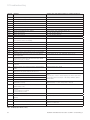
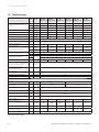
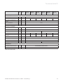
Technical data ....................................................42
Installation and maintenance instructions ecoCRAFT - 0020055744_03
Notes on the documentation 1
1
Notes on the documentation
The following instructions are intended to help you
throughout the entire documentation.
Further documents apply in combination with this installation and maintenance manual.
We accept no liability for damage caused by a failure
to observe these instructions.
Documents which are also valid and auxiliary service
equipment.
For the owner of the system:
Operating manual
Short-form instructions
No. 00200587171
No. 0020063363
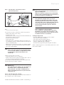
Auxiliary service equipment:
The following test and measuring equipment are required for inspection and maintenance:
– CO2 measuring instrument
– Pressure gauge
– flue gas analyser
– Torque wrench
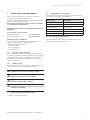
1.3
Applicability of the manual
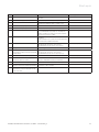
These installation instructions apply exclusively to appliances with the following part numbers:
Appliance type
Part number
VKK GB 806/3-E-H
0010005410
VKK GB 1206/3-E-H
0010005411
VKK GB 1606/3-E-H
0010005412
VKK GB 2006/3-E-H
0010005413
VKK GB 2406/3-E-H
0010005414
VKK GB 2806/3-E-H
0010005415
Table 2.3 Overview of the part numbers
The part number of the appliance can be found on the
identification plate (see Section 2.2).
1.1
Storage of the documents
Please hand this installation and maintenance instruction manual and the auxiliary equipment to the operator
of the installation, whose responsibility it is to ensure
the manuals and auxiliary equipment are available
whenever required.
1.2
Symbols used
Please observe the following when operating the unit:
Safety instructions in this installation manual!
Danger!
d Immediate
risk of serious injury or death!
Danger!
e Danger of death from electric shock!
Danger!
H Danger
of burning and scalding!
Caution!
a Potentially
dangerous situation for the product
and the environment!
h Note
Useful information and instructions.
• Symbol for a necessary task
Installation and maintenance instructions ecoCRAFT - 0020055744_03
3
2 Description of the appliance
2
2.1
Description of the appliance
Model description
Designated country (designation
in accordance with ISO 3166)
Appliance type
Category
of permit
Type of gas
Nominal heat output range P (kW)
VKK GB 806/3-E-H
13.6 – 78.2 (80/60 °C)
14.1 – 80.4 (60/40 °C)
14.7 – 84.1 (40/30 °C)
VKK GB 1206/3-E-H
21.3 – 113.4 (80/60 °C)
22.1 – 116.5 (60/40 °C)
23.1 – 121.8 (40/30 °C)
VKK GB 1606/3-E-H
26.2 – 156.5 (80/60 °C)
27.1 – 160.8 (60/40 °C)
28.4 – 168.2 (40/30 °C)
GB (Great Britain)
IE (Ireland)
G20 (natural gas E)
I2H
VKK GB 2006/3-E-H
43.1 – 196.8 (80/60 °C)
44.2 – 201 (60/40 °C)
46.2 – 210.2 (40/30 °C)
VKK GB 2406/3-E-H
47.0 – 236.2 (80/60 °C)
48.2 – 241.2 (60/40 °C)
50.4 – 252.2 (40/30 °C)
VKK GB 2806/3-E-H
51.0 – 275.5 (80/60 °C)
52.3 – 281.4 (60/40 °C)
54.7 – 294.3 (40/30 °C)
Table 2.1 Overview of types of unit
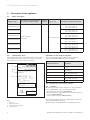
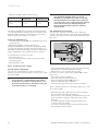
2.2
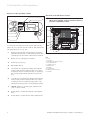
Identification plate
The identification plate is mounted on the front of the
boiler under the front casing. It becomes visible after
the front section of the casing is removed.
Explanation of the model designation
The following table explains the model designation,
using the VKK GB 2806/3-E-H as an example.
VKK GB 2806/3-E-H
Equipment
VKK
Vaillant gas-fired condensing
boiler
GB
Great Britain
280
Unit size (output in kW)
6
Gas-fired condensing boiler
3
Boiler production series
H
Gas category I2H
1
Vaillant GmbH Remscheid / Germany
Serial-Nr. 21080400100054150006000000N0
2
VKK GB 2806/3-E-H
ecoCRAFT
3
4
Typ B23, B23P, C33, C43, C53, C63, C83
GB, IE, cat. I2H
2H, G20 - 20 mbar
P(40/30°C) =
P(60/40°C) =
P(80/60°C) =
Q
=
Q
=
NOx class 5
Tmax. =
PMS =
V
54,7
52,3
51,0
52,0
57,7
-
294,3
281,4
275,5
280,0
310,8
kW
kW
kW
kW NCV (Hi)
kW GCV (Hs)
85 °C
6 bar
=
17,37 I BED 92/42 ****
230 V ~ 50 Hz 320 W
IP 20
Read the instructions fully before installing or using the appliance!
The appliance must be installed in accordance with the
manufacturer's instructions and the regulations in force and only
in a suitably ventilated space!
Please observe the maintenance instructions as outlined in the
instruction manual!
0063 08
CE-0063BS3986
EAN-CODE
Table 2.2 Explanation of the model designation
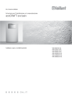
2.3
CE label
CE labelling shows that the appliances comply with the
basic requirements of the following directives:
– Gas appliances directive (90/396/EEC)
– Electromagnetic compatibility directive with threshold
class B (2004/108/EEC)
– Low voltage directive (2006/95/EEC)
Fig. 2.1 Identification plate
Key
1 Serial No.
2 Model designation
3 Type approval designation
4 Technical Data
4
The appliances meet the basic requirements of the efficiency requirements directive
(Council Directive 92/42/EEC) as condensing boilers.
Installation and maintenance instructions ecoCRAFT - 0020055744_03
Description of the appliance 2
2.3 Intended use
Vaillant gas-fired condensing boilers
VKK GB 806/3 -2806/3-E-H are constructed in accordance with state of the art technology and recognised
safety regulations.
Nevertheless, there is still a risk of injury or death to the
user or others or of damage to the device and other
property in the event of improper use or use for which it
is not intended.
This unit is not intended for use by persons (including
children) having limited physical, sensory or mental capacities or who have inadequate experience and/or
knowledge, unless they are supervised by a person responsible for their safety or have been given instructions by him regarding the operation of the unit.
Children must be supervised to ensure that they do not
play with the unit.
The boiler is suitable for connection to sealed central
heating installations.
Any other or additional use is considered to be improper. The manufacturer or supplier is not liable for any resulting damage. The user alone bears the risk.
Use includes observance of the operating and installation manuals and all other applicable documents, as well
as adherence to the maintenance and inspection conditions.
Equipment
- Modulation range, see Table 2.3
- Reduced environmental impact as a result of the
extremely low emission of toxic substances:
NOx <60 mg/kWh and CO < 20mg/kWh
- Compact high efficiency heat exchanger with NTC
sensor
- Modulating multi-port burner
- Class A gas valve
- Gas - air mixture regulation
- Electronically controlled fan
- Flow manifold with NTC sensor
- Return manifold with NTC sensor
- Safety temperature limiter (STL)
- Operating panel with multi-function display
- Flue gas temperature max. 80 °C
- Condensate collector
- Polypropylene siphon
- Internal frost protection function
- Interface for control of a modulating pump
- Internal cylinder temperature regulation
- Interface for temperature-based activation
- Adjustable boiler feet
Regulation range
Minimum Load
a
Caution!
Any improper use is forbidden.
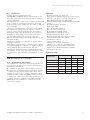
2.4
Construction and function
The ecoCRAFT is a gas-fired condensing boiler which is
used as a heat producer for hot water central heating
installations up to 85 ºC.
It is suitable for operation in new installations and for
modernisation of existing heating installations in multioccupancy houses and in business units. The boiler is
suitable for connection to commercial heating control
systems, Vaillant controls and BEMS systems. The boiler
is suitable for connection to open-flue systems. Air for
combustion must be supplied in accordance with BS
6644. The boiler is suitable for connection to room
sealed flues „Type C“.
Installation and maintenance instructions ecoCRAFT - 0020055744_03
Maximum Load
Appliance type
kW
%
kW
%
VKK GB 806/3-E-H
14.0
17.5
80.0
100
VKK GB 1206/3-E-H
22.0
19.0
115.9
100
VKK GB 1606/3-E-H
27.0
17.0
160.0
100
VKK GB 2006/3-E-H
44.0
22.0
200.0
100
VKK GB 2406/3-E-H
48.0
20.0
240.0
100
VKK GB 2806/3-E-H
52.0
19.0
280.0
100
Table 2.3 Regulation ranges
5
2 Description of the appliance
Overview of the operating controls
Overview of the functional controls
1
2
9
h Note
When using Vaillant controls both dials must be
turned to maximum position.
1
10
3
8
2
7
3
9
6
5
4
Fig. 2.2 ecoCRAFT operating controls
8
4
7
To open the front panel, hold the recess and fold the
panel out. You can now see the controls, which have the
following functions (cf. fig. 4.1):
1
Display indicating the current heating flow temperature, the pressure of the heating system, the
operating mode and other additional information
2
Button "i" for displaying information
3
Controller (accessory)
4
On and Off switch
5
"+" button for navigating forwards through the
display view (used by expert technician to specify settings and for troubleshooting) or displaying
the storage temperature (VC with cylinder sensor)
6
"–" button for navigating backwards through the
display view (used by expert technician to specify settings and for troubleshooting) and for displaying the filling pressure of the heating system
7
"Reset" button for resetting the system in the
case of specific faults
8
Rotary knob to adjust the heating flow temperature.
9
Rotary knob to adjust the hot water temperaure
6
6
5
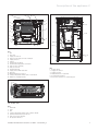
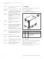
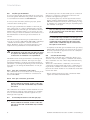
Fig. 2.3 View from the right hand side
Key
1 Flow
2 Gas pipe
3 Air inlet box with dust filter
4 Condensate pan
5 Supply air hose
6 Drain point
7 Return
8 Return NTC
9 Water pressure sensor
10 Venturi
Installation and maintenance instructions ecoCRAFT - 0020055744_03
Description of the appliance 2
15
14
16
1
13
2
1
12
11
3
10
2
9
8
4
7
6
6
5
5
Fig. 2.4 View from the left hand side
Key
1 Fan
2 Gas valve
3 Supply air silencer
4 Inspection opening for heat exchanger
5 Supply air hose
6 Siphon
7 Condensate discharge
8 Condensate trap/siphon connection
9 Flue gas STL (optional)
10 Flue gas silencer
11 Condensate trap
12 Supply air box with dust filter
13 Gas pipe
14 Boiler NTC and STL sensor
15 Safety temperature limiter (STL) reset button
16 VR35 0-10 V pump module
4
3
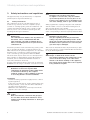
Fig. 2.6 Front view
Key
1 Control panel
2 Supply air silencer
3 Supply air filter
4 Neutralisation box (optional)
5 Condensate discharge
6 Inspection opening for condensate pan
7
6
5
1
2
4
3
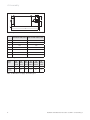
Fig. 2.5 Plan view
Key
1 Flow NTC
2 Flow
3 Fan
4 Safety temperature limiter (STL) and block NTC
5 Ignition and monitoring electrode
6 Flue gas pressure monitor
7 Air pressure monitor
Installation and maintenance instructions ecoCRAFT - 0020055744_03
7
3 Safety instructions and regulations
3
Safety instructions and regulations
The appliance may only be installed by a competent
qualified person registered with Corgi.
Caution!
a Damage to the screwed connections!
To tighten or loosen bolts, only use suitable
open-ended spanners (do not use pliers or extensions etc.) Improper use or unsuitable tools
can cause damage, such as gas or water leaks!
3.1
Safety instructions
The combustion air fed to the unit must be free of
chemicals e.g. fluorine, chlorine or sulphur. Sprays,
solvents or cleaning agents, paints and adhesives can
contain such materials which can, in certain circumstances, lead to corrosion when operating the unit,
including the flue gas installation.
Always tighten the couplings fixing the flow distributor
and the return collector to the heat exchanger block
with a torque wrench set to 12 Nm.
On sealed heating installations, a type-approved safety
valve corresponding to the heat capacity must be fitted.
Caution!
a Malfunction!
Caution!
a Damage
to the gas valve!
In business premises such as hairdressing salons, painting or carpentry workshops, cleaning businesses etc.,
when installed as an open flued appliance. It is desirable
that the boiler is installed in a purpose made boiler
room conforming to the guidance within BS 6644.
The boiler shall only be sited on floors and adjacent to
walls capeable of withstanding at least 65 degrees C.
(However, the recommended minimum distance in
section 4.3.2 must be observed).
A safety valve must be fitted to the boiler as defined in
BS 6644 for both single or modular cascades of boilers.
The electrical installation must only be made by a qualified electrician in accordance with BS 7671 and the Electricity at Work Regulations.
The combustion air must be free of particles or
the burner can be contaminated with dirt.
Take particular care that no building dust or
fibres of insulating material are present in the
combustion air.
The gas regulating block may be tested for
leakage only with a maximum pressure of 110
mbar! The operating pressure must not exceed
60 mbar! If these pressures are exceeded, the
gas valve may be damaged.
Danger!
e Danger
of death from electric shock!
The supply terminals in the terminal box of the
device are under voltage even if the mains
switch is off. Before working on the appliance,
turn off the power supply and secure it against
being switched on again!
concerning flue design:
h Note
Modulation of the boiler together with
combustion air matching produces high values
of combustion efficiency. This requires
technical evidence of the suitability of the flue
in according with the relevant standards.
Installation
• Flush the heating system thoroughly before connecting the appliance!
In this way, residue such as cinders, hemp, putty, rust,
welding residues, coarse dirt and similar substances
are removed from the pipes.
Otherwise such substances can be deposited in the
appliance and cause damage.
Caution!
a Leaks!
Make sure that the connection and gas pipes
are not under stress when installed to avoid
leakage in the heating installation or at the gas
connection!
8
Installation and maintenance instructions ecoCRAFT - 0020055744_03
Safety instructions and regulations 3
Start-up
The heating system must be thoroughly cleansed before
use. The boiler heat exchanger is made from aluminium
and any inhibitor used must be suitable for use with aluminium. Always seek the advice of a professional water
treatment company. Advice may be sought from:
Fernox
Cookson Electronics
Forsyth Road
Sheerwater
Woking
Surrey
GU21 5RZ
Danger!
d Danger of explosion through gas leakage! When
installing, maintaining and repairing the unit,
always check the gas carrying components, including the burner seals, for gas leaks. We recommend the use of an electronic gas sensor instrument.
Danger!
H Danger of burning and scalding!
There is danger of being injured or scalded by
the boiler and by all components carrying
water. Only carry out work on these
components once they have cooled down.
Sentinel Performance Solutions Ltd
The Heath Business & Technical Park
Runcorn
Cheshire
WA7 4QX.
Troubleshooting
• Disconnect the unit from the mains before starting
work. Close the gas valve and the maintenance valves.
• Drain the appliance if you want to replace water-carrying components within.
If frost or corrosion preventative is added to the heating
water this can cause changes in the seals and can cause
noises to be created during the heating process. Vaillant
assumes no liability for this and such consequential
damages.
• Inform the user of the procedure for frost protection.
Danger!
e Danger
of death from electric shock!
The boiler is suitable for installation to artificially softened water supplies.
Only for natural gas:
The inlet gas working pressure must not be less than 17
mbar whilst operating at maximum output.
Inspection and maintenance
Inspection, maintenance and repair work should only be
undertaken by an approved heating installation company. Inspections/Maintenance work not carried out can
result in damage to property and personal injury.
The electrical installation must only be made by a qualified electrician in accordance with BS 7671 and the Electricity at Work Regulations.
Danger!
e Danger
of death from electric shock!
The supply terminals in the terminal box of the
device are under voltage even if the mains
switch is off. Before working on the appliance,
turn off the power supply and secure it against
being switched on again!
• Protect the switch box from water spray.
Installation and maintenance instructions ecoCRAFT - 0020055744_03
The supply terminals in the terminal box of the
device are under voltage even if the mains
switch is off. Before working on the appliance,
turn off the power supply and secure it against
being switched on again!
• Make sure that no water falls on live components
(e.g. electronic box etc.).
• Use only new gaskets and O-rings.
• Perform a functional test after you have finished this
work.
3.2
Regulations
To ensure the safe installation of your appliance, the
laws, regulations, technical rules and standards pertaining to the installation must be considered and adhered
to.
Attention shall be paid to the regulations, guidelines and
standards in force. In particular, reference shall be
made to the following regulations, guidelines, standards
and rules:
The electrical connections to the boiler MUST be in accordance with the BS 7671, The Electricity at Work Act,
and tested accordingly.
The Clean Air Act 1993 and the 3rd Edition of the 1956
Clean Air Act.
The Building Regulations, England and Wales, The Building Standards, Scotland, and any requirements determined by the local authorities within.
Water supply (water fittings) regulations 1999.
Detailed recommendations are also contained in the following documents:
9
3 Safety instructions and regulations
4 Assembly
BS 5854
Code of practice for flues and flue
structures in buildings.
BS EN 12828
Design of water-based heating systems.
BS 6644
Specification for the installation of gasfired hot water boilers with rated inputs
between 70kW (net) and 1.8MW (net)
(2nd and 3rd family gases).
Code of practice for low temperature
heating systems with outputs greater
than 45kW.
Part 1 Fundamental and design considerations.
Part 2 Selection of equipment.
Part 3 Installation, commissioning and
maintenance.
BS 6880
BS 6981
Installation of low pressure gas pipework of up to 28mm in domestic
premises.
BS 7074
Application, selection and installation of
expansion vessels and ancillary equipment for sealed water systems.
Part 1 Code of practice for domestic
heating and hot water.
Part 2 Code of practice for low and medium temperature hot water systems.
BS 6700
Specification for the design, installation, testing and maintenance of services supplying water for domestic use
within buildings and their curtilages.
4
Assembly
The boilers are supplied ready for connection in a packaging unit with the casing fitted.
4.1
Scope of delivery
• Check the delivery for completeness and potential
damage using the following overview.
2
1
Fig. 4.1 Scope of delivery
Item
Quantity
Name
1
1
Unit (casing fitted)
2
5
Operating manual,
Short operating manual,
Installation manual,
Guarantee card
Institute of Gas Engineers Publications
IGE/UP/1
Soundness testing and purging of industrial and commercial gas installations.
IGE/UP/1A
Soundness testing and purging of small
low pressure industrial and commercial
natural gas installations.
IGE/UP/10
Installation of gas appliances in industrial and commercial premises.
Part 1 Flued appliances
10
Table 4.1 Scope of delivery
4.2
Accessories
The following accessories are required for the installation in addition to the necessary safety and isolating devices:
– Heating controller (e.g. VRC 430 or 630),
– Low loss header (optional),
– Boiler circulating pump (with fixed or variable speed),
– Neutralisation box, if required.
Installation and maintenance instructions ecoCRAFT - 0020055744_03
Assembly 4
4.3
Installation location
• The unit should be installed in a frost-protected room.
The unit can be operated in ambient temperatures between approx. 4 °C and 50 °C.
When selecting the installation site, the weight of the
boiler including the water inside, as determined from
the "Technical Data" table (Chapter 12), must be taken
into account.
4.3.2 Recommended minimum distances for
installation
500
A heating boiler pedestal (sound-deadening) or similar
installation can be used to provide noise deadening; we
recommend installing the unit on a boiler support foundation 5 to 10 cm thick.
4.3.1
Regulations pertaining to the installation
location
300
50
Note!
h The boiler should be installed in a purpose built
500
boiler room in accordance with BS 6644
The approval of the relevant building regulations authority must be obtained for the selection of the installation site and for the characteristics of the ventilation
and flue gas handling systems of the installation room.
The combustion air fed to the appliance must be physically free of chemical substances that contain,
e.g. fluorine, chlorine and sulphur. Sprays, paints, solvents and cleaning materials and adhesives contain
such substances, which can, during operation of the
unit, lead to corrosion under unfavourable conditions,
including in the flue gas installation.
Caution!
a Malfunction!
Fig. 4.2 Recommended distances during installation
• Keep to the recommended minimum distances in
order to be able to carry out assembly and maintenace work with as little impediment as possible.
4.3.3 Aligning the boiler
• The boiler should be levelled using the height-adjustable feet to prevent water condensate from flowing
out of the condensate collector.
4.4
Dimensions
The combustion air must be free of particles or
the burner can be contaminated with dirt.
Take particular care that no building dust or
fibres of insulating material are present in the
combustion air.
R2‘‘
981,5
819
1285
R2‘‘
495
For this reason, the boiler is factory-fitted with a dust
filter. During a construction phase the boiler must only
be operated with this filter.
• Replace the filter after 10 weeks at the most, and
even sooner if there is heavy contamination.
• Remove the filter after the completion of the construction phase.
• Clean the supply air hose.
1305
678
1 1/2“
152,5
214,5
90
695
Fig. 4.3 Pipe connection dimensions
Installation and maintenance instructions ecoCRAFT - 0020055744_03
11
4 Assembly
A
B
C
G
E
D
F
Fig. 4.4 Appliance dimensions
VKK GB 80-1606/3-E-H
VKK GB 200-2806/3-E-H
A
165
165
B
326
326
C
369
369
D
50
50
A
1168
1478
F
1240
1550
G
22
22
Table 4.2 Appliance dimensions
VKK
GB
806/
3-E-H
VKK
GB
1206/
3-E-H
VKK
GB
1606/
3-E-H
VKK
GB
2006/
3-E-H
VKK
GB
2406/
3-E-H
VKK
GB
2806/
3-E-H
Flue pipe
150
150
150
200
200
200
Supply
air pipe
130
130
130
130
130
130
Boiler
Type
Table 4.3 Dimensions of supply air and flue pipes
12
Installation and maintenance instructions ecoCRAFT - 0020055744_03
Installation 5
5
5.1
Installation
5.2
Removing the casing
General information on the heating system
1
a
Caution!
Malfunctions!
Flush the heating system thoroughly before
connecting the appliance! In this way, residue
such as cinders, hemp, putty, rust, welding
residues, coarse dirt and similar substances are
removed from the pipes. Otherwise such
substances can be deposited in the appliance
and cause damage.
• A safety valve must be fitted to the boiler as described in BS 6644.
• The system shall be vented at high points to prevent
air locks.
• The system shall be filled and drained in accordance
with guidance in BS 6644 and the current Water Regulations.
The safety temperature limiter fitted to the boiler
serves, in addition to the water pressure switch, as a
low water level safety device.
The fault-induced shut-down temperature of the boiler
is approx. 110 °C (nominal shut-down temperature 110 °C,
tolerance - 6 K).
• If plastic pipes are used in the heating system, you
must fit a suitable pipe thermostat on this section of
the heating system. This is required to protect the
heating installation from temperature-related damage.
The thermostat can be wired to the plug for the contact thermostat (blue ProE plug).
• When using non-oxygen barrier plastic pipes in the
heating system, you must install to plate to plate heat
exchanger downstream for system separation, to prevent corrosion in the boiler.
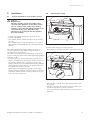
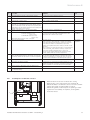
Fig. 5.1 Opening the front flap
To remove the casing, proceed as follows:
• Open the front flap by lifting the silver handle strip (1).
2
Fig. 5.2 Removing the front casing
• Unscrew the screw (1) above the multi-function operating panel.
• Pull the front panel in the upper section towards you.
• Lift the front panel in order to remove it.
• You can now remove the remaining casing sections as
required.
Installation and maintenance instructions ecoCRAFT - 0020055744_03
13
5 Installation
5.3
Gas connection
The gas installation may only be carried out by a competent and qualified engineer. The legal directives and
any local regulations for gas supply companies must be
observed while doing this.
The gas supply line must be constructed in accordance
with the Gas Safety (installation and use) Regulations
and IGE UP1, IGE UP1A, IGE UP1B and IGE UP2.
5.4
Heating side connection
1
Caution!
a Leaks!
2
Make sure that the connection and gas pipes
are not under stress when installed to avoid
leakage in the heating installation or at the gas
connection!
• The cross-sections of the gas pipes should be selected
to suit the nominal boiler load.
Caution!
a Damage
to the gas valve!
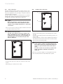
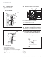
Fig. 5.4 Heating side connection (rear of boiler)
The gas valve may be tested for leakage only
with a maximum pressure of 110 mbar! The operating pressure must not exceed 60 mbar! If
these pressures are exceeded, the gas valve
may be damaged.
1
• Connect the heating flow to the heating flow connection (1).
• Connect the heating return to the heating return connection (2).
• Fit the required isolation valves between the heating
installation and the boiler and fit the relevant safety
devices and a pressure gauge.
a IfCaution!
the volume of water circulating falls below
the nominal value, the temperature difference
will be too great and the burner will start to
cycle.
For this reason it is necessary to ensure the
water circulation quantities specified in
Table 5.1.
The boiler circulation pump is not integrated into the
boiler and thus must be fitted within the system.
Fig. 5.3 Gas connection (rear of boiler)
• Connect the gas line to the gas connection (1) on the
boiler.
• Check the gas connection for leaks.
14
Installation and maintenance instructions ecoCRAFT - 0020055744_03
Installation 5
The following pumps and low loss headers are recommended for use with the respective boilers:
Boiler
Nominal water
circulation volume
for 20 K difference
Speed regulated
high-efficiency pump
3 stage conventional pump
Low loss header
VKK GB 806/3-E-H
3.44
Item no. 0020022253
Item no. 309 442
WH 95 (Item No. 306 721)
VKK GB 1206/3-E-H
4.99
Item no. 0020022253
Item no. 309 442
WH 160 (Item No. 306 726)
VKK GB 1606/3-E-H
6.88
Item no. 0020022253
Item no. 309 442
WH 160 (Item No. 306 726)
VKK GB 2006/3-E-H
8.60
Item no. 0020022254
Item no. 309 443
WH 280 (Item No. 306 725)
VKK GB 2406/3-E-H
10.33
Item no. 0020022254
Item no. 309 443
WH 280 (Item No. 306 725)
VKK GB 2806/3-E-H
12.05
Item no. 0020022255
Item no. 0020016930
WH 280 (Item No. 306 725)
Table 5.1 Application of pumps and low loss headers
5.5
Connecting the DHW cylinder
16a
13
3
230 V~
21a
3
21b
2
2 BUS
10
ϑ
230 V~
2
2 3
42a
3
3
3
5
2
30
2b
3
3
5
24
19
30
15
3
30 46
17b
2c
4
2
52
ϑ
31
30
43
27
47
17a
33
1
2a
45
32
42b
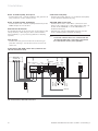
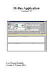
Fig. 5.5 Heating circuit schematic with low loss header
Key
1 ecoCRAFT gas-fired condensing boiler
2a Boiler circulation pump (modulated)
2b Heating circuit pump (mixer circuit 1)
2c Heating circuit pump (mixer circuit 2)
5 Domestic hot water cylinder
10 Radiator thermostat valve
13 VRC 630 weather compensator
15 3-way mixer
16 External sensor
17a Flow temperature sensor (heating circuit 1)
17b Flow temperature sensor (heating circuit 2, mixer circuit)
19 Maximum temperature thermostat
21a Remote control unit VR 80 or VR 90 (radiator circuit)
Installation and maintenance instructions ecoCRAFT - 0020055744_03
21b Remote control unit VR 80 or VR 90 (underfloor circuit)
24 Cylinder temperature sensor
27 Cylinder charging pump
30 Non-return valve
31 Regulator valve
32 Cap valve
33 Sludge separator
42aExpansion relief valve
42bExpansion vessel
43 Safety group
45 Low loss header
46 Circulation pump
47 Air separator
52 Room temperature controlled valve
15
5 Installation
5.6
Air/flue gas installation
In case you use air/flue gas pipes which are licenced to
be used together with the boiler, please observe the enclosed installation instructions 0020058722.
In case you use customary air/flue gas pipes, please
overserve the following notes:
The flue gas system must be suitable for the flue gas
duct of the boiler (e.g. range oftemperature, pressure
and leak-tightness). The flue gas duct must be labelled
with the CE conformity mark or, if necessary, be certified according to national standards. The instructions of
the manufacturer of the flue gas ducts must be observed.
The dimensioning of the flue gas system must be carried out according to EN 13384-1 (EN 13384-1 - Chimneys
- Thermal and fluid dynamic calculation methods Part 2: Chimneys serving one heating appliance). The
required device parameters are listed in table 12.1.
Caution!
a The diameter of the flue gas pipe must at least
be equal to the diameter of the flue gas spigot
of the boiler. A reduction is not permitted.
Furthermore the valid type standards concerning flue
gas systems must be observed. The respective type
standard determines conditions and safety-related requirements concerning the planning, erection and startup as well as concerning the maintenance of flue gas
systems.
5.6.1 Flue gas connection, room-sealed
The combustion air is fed to the boiler via ducting from
the outside. The boiler room must be constructed as
stated in BS 6644.
5.6.2
All condensing boilers are fitted with special connection
flanges for connecting condensate secure and overpressure leak-tight flue gas pipes.
• For adjusting purposes, the flue pipe must be fitted
with a cleaning opening having a diameter of at least
100 mm. It may be necessary to have openings of larger diameter for cleaning the flue pipe, depending upon
the diameter of the pipe.
Note!
h The user must provide a measurement opening
on the customer side of the flue pipe, externally
to the boiler casing.
Note!
A condensate trap is fitted to the flue gas connection on the boiler to prevent contaminated
condensate from getting into the boiler. The
drain of this condensate trap is connected to
the siphon on the boiler.
• If required, fit the flue gas line with the flue gas safety
temperature limiter which is provided as an accessory.
The flue pipe must be approved for use at a temperature of at least 120 °C.
5.8
Condensate discharge
The pH value of the flue gas condensate, which is produced at a rate of max. 1 kg/m3, is between 3.5 and 4.5.
The condensate does not contain any prohibited heavy
metal ions.
The boiler is fitted with a condensate collector and a
condensate discharge with siphon. The condensate arising from the combustion is either fed directly via the siphon into the drain channel or first neutralised and then
fed into the drain.
• Before starting up the boiler, the condensate water
syphon should be filled with water.
Flue gas connection, open flued
h Note!
Ensure that the horizontal section of the flue
gas pipe is run with a downward slope towards
the boiler!
The combustion air is taken from the installation room.
The ventilation openings in the installation room must
be in accordance with the relevant regulations (condensing boilers Type B).
5.7
Connecting the boiler to the flue gas pipe
h Note!
Ensure that the horizontal section of the flue
gas pipe is run with a downward slope towards
the boiler!
16
Installation and maintenance instructions ecoCRAFT - 0020055744_03
Installation 5
Note!
h For boilers up to 200 kW:
If required, a neutralisation device with
condensate feed pump from the range of
Vaillant accessories can be connected.
For boilers above 200 kW:
If required, an in-line neutralisation device from
the range of Vaillant accessories can be
connected.
3
5.9
Electrical connection
Danger!
1
2
Fig. 5.6 Siphon
Key
1 Siphon
2 Drain hose to the neutralisation box (optional) or to the drain
3 Hose from the condensate trap to the siphon
Danger!
d Risk
of poisoning from leaking flue gas!
If the device is operated with an empty
condensate siphon, there is a risk of poisoning
from the escaping flue gases. Be absolutely
certain, therefore, to fill the siphon before
starting up.
Connecting the condensate drain
The chimney drainage line is run on a slope using suitable plastic or stainless steel piping with a minimum
cross-section of DN 20. The condensate water piping to
the waste outlet is also installed at an angle using a
DN 25 pipe (plastic or stainless steel) and must go to
the nearest waste water outlet. The take-off from the
boiler is effected by means of a ø 21 mm plastic pipe.
The discharge point must remain visible.
e Risk of fatal electric shock from live connec-
tions!
The electrical installation must be carried out
by an electrical specialist, who is responsible
for complying with the existing standards and
guidelines. All electrical work must be in accordance with the Electricity at Work Act and
BS 7671.
Danger!
Risk of fatal electric shock from live connections!
• Always switch off the power supply to the
appliance first. Only after this can the installation be carried out. Continuous voltage is
present on the L and N terminals, even when
the main switch is turned off.
Danger!
Risk of fatal electric shock from live connections!
Mains and low-voltage cables (e.g. sensor wiring) must be run separately from each other.
Use the divided cable channel on the left hand
side section for this.
Caution!
a Access to the main switch (4) (see Fig. 2.2)
must be guaranteed at all times and must not
be covered or blocked, so that the appliance
can be switched off in the event of a malfunction.
To simplify the wiring, the appliance is equipped with
System ProE connectors and is ready for connecting.
The mains cable and all the other connecting cables
(e.g. from the room thermostat) can be connected to
the System ProE plugs that have been provided in each
case.
Installation and maintenance instructions ecoCRAFT - 0020055744_03
17
5 Installation
Danger!
Note
e Danger of death from electric shock!
h Ensure that the boiler room complies wit the
The connection should be wired as follows:
• Open the front flap by lifting the silver handle strip.
• Unscrew the screw above the multi-function operating
panel.
• Pull the front casing in the upper section towards you
and lift it in order to remove it.
• Hinge the electronics box forward.
• Unclip the rear part of the electronics box cover and
hinge it upwards.
• Pass the cables through the cable entry in the rear
wall of the appliance and through the unit into the
electronics box.
• Use the cable channel on the left hand side section for
feeding the cable through the unit.
5.9.2 Connecting a controller
The Vaillant VRC 630 controller or an externally mounted Vaillant VRC 430 controller must be connected via
the "Bus" connection (red plug) in accordance with Fig.
5.8 or Fig. 5.9. The bridge between the terminals 3 and
4 should remain intact (lilac plug).
The sensors and the system components that are not
listed in Section 5.10.3 are connected to the controller.
The electrical connection to the Vaillant heating control
unit is shown in Fig. 5.7.
Further information can be obtained from the regulator
instructions.
The fan is connected to a 230 V/50 Hz supply.
requirements of BS 664 and IGE UP10.
Caution!
a Risk
of malfunction!
Do not use the same strain relief for the extra
low voltage cable as for the mains cable!
• Take care to ensure spatial separation of the mains
and extra low voltage cables.
• Secure the cables with the strain reliefs.
• Carefully strip the insulation from the cable ends.
• Then close the rear cover of the electronics box and
press it down until it audibly engages.
• Hinge the electronics box up.
• Fasten the front casing.
• Screw the screw above the multi-function operating
panel in again.
• Close the front cover.
5.9.1 Connecting the mains cable
The nominal voltage of the mains must be 230 V; if the
mains voltage is more than 253 V or below 190 V, functional impairment is possible. The mains feed must be
connected via a fixed connection and an isolating device
having a minimum contact opening of 3 mm (e.g. fuses,
power switches).
• Connect the mains cable to the terminals provided, N,
L and PE, in the plug.
18
Installation and maintenance instructions ecoCRAFT - 0020055744_03
Installation 5
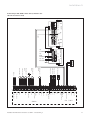
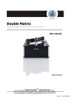
Connecting electrical accessories and internal
wiring
green
X18
Option - ext. controller/ room thermostat 3-4 (contact)
3
Mains input
N
L
Option - ext. controller/ room thermostat 7-8-9 (analogue)
7
+
-
Bus connection (controller/room
thermostat, digital)
Contact thermostat
2
1
AF
X22
X40
Edge connector
RF
DCF
1
0
0
Pump
module
PWM input.
Remote control – Circulation pump
External sensor
Flow line sensor (Option)
DCF connection
Plug for VCR 4xx
Earth
controller accessory
Earth
or ZP single start
Pump PWM signal
6
Accessory module signals
1
17
3
4
15
10
6
24 V
0-10V output
9
8
6 FB
X41
0 .. 10V Pump signal
L
24V Supply
Mains voltage
X1
Heating water pump
N
5
4
blue
X11
red whiteSSturquoise purple
L
Extra-low voltage
Mains voltage
Accessory
module VR40
Edge connector
N
Charging pump
N
L
230 V~
grey
X13
blue
black
X12
5.9.3
24 V
red
black
1 + 24 V
2 Hall signal
230 V~
L
Fan
grey
N
4 PWM signal
5 Earth
blue
red
P
green
green
24 V
Air pressure switch
blue
18
X20
9
2
16
5
Gas valve
red
+
red
black
Extra-low voltages - plug
black
X29
Ignition
unit
X14
7
8
12
13
14
8
18
17
19
20
9
6
J
Boiler block sensor
black
J
Flow sensor
clear
J
Return sensor (R25=10k)
(R25=2k7)
(R25=10k)
black
blue
black
DE
black
black
black
white
P
Flue gas pressure
sensor
Cylinder contact
"C1-C2"
brown
white
black
orange
white
black
black
red
J
1
2
4
green
black
Flue gas temperature limiter
J
AT
AT only, otherwise bridged
J
STB
22
5
red
red
P
Cylinder sensor
(accessory)
(R25=2k7)
Water pressure sensor
Coding resistor
4320 Ù
black
Ignition electrode
white
Equipment earth
Fig. 5.7 Connecting electrical accessories and internal wiring
Installation and maintenance instructions ecoCRAFT - 0020055744_03
19
5 Installation
Boiler circulation pump, fixed speed
• Connect the boiler circulation pump to the green ProE
plug connector on the connection rail.
Condensate feed pump
• Connect the alarm output of a condensate feed pump
to the "Contact thermostat" plug.
Boiler circulation pump, modulating
• Connect the boiler circulation pump additionally to the
0-10V adapter box in the unit.
VRC 430, 630 control units
• Connect the 2 wires of the "Bus" connections (red
plug) to the connections of the same name in the controller on the VRC 630, or on the VRC 430 if it is
mounted externally.
• Alternatively, plug the VRC 430 controller into the
boiler operating panel (internal mounting).
External flow thermostat
A flow thermostat can be electrically incorporated in the
safety chain by connecting it to the "contact thermostat" terminals, e.g. for protecting underfloor heating
systems.
Note!
h If several contacts are to be connected to the
"Contact thermostat" connection, They must
be connected in series, not in parallel!
Flue gas STL
• Connect the flue gas STL in the line to the flue gas
pressure cartridge - see the enclosed accessories instructions.
Connecting a VRC 430 control unit (controller outside the electronics box)
X13
VRC 430
Bus
red
Charging
pump
Heating
water
pump
ϑ
Cylinder sensor
AF
RF
DCF
0
0
6 FB
1
Network
Bus
Pump Pump
tur2
red white quoise purple 1
green grey
+
-
Edge connector
blue
red
X18
Boiler
X1
X41
DCF / AF
0 - DCF- AF
Network
Fig. 5.8 Connecting a VRC 430 control unit
20
Installation and maintenance instructions ecoCRAFT - 0020055744_03
Installation 5
Connecting a VRC 630 control unit (controller outside the electronics box)
230 V~ "2 from 7"
DCF / AF
0 - DCF - AF
Network
2
1
N
e.g. ext.
Gas valve
Boiler
X12
X40
X13
L
N
rel 2
rel 1
rel 1
green brown yellow white
L
N
X18
L
N
X1
7
8
9
Network
Pump Pump
Network
1
2
purple green grey
3
4
5
X14
Edge connector Bus
red blue red white
—
+
X3
Cylinder sensor
7
8
9
7-8-9 II
7-8-9 I
C1 C2
External sensor
Bus
Telephone
Distance Switch.
1x ZP
Sp
KF
VF 3
VF 2
Stage 1
VRC 630
VF 1
HK 3-P
7
8
9
C2
C1
AF
0
DCF
+
-
2
1
2
1
2
1
2
1
ϑ
ϑ
2
1
2
1
ϑ
Flow sensor 3
Flow sensor 2
2
1
2
1
2
1
N
L
N
Open
Closed
N
L
N
Open
Closed
230V Network
230V Network
LP/UV
ZP
HK 1-P
HK 2 Mischer
HK 2-P
Stage 2
KP / AV
Heating
circuit 3 mixer
N
Open
Closed
ϑ
Heating water
pump 3
Flow sensor 1
M
N
L
N
L
N
L
N
L
N
L
21
Installation and maintenance instructions ecoCRAFT - 0020055744_03
1
2
X40
5 V / 24 V
230 V~
L
N
e.g.
fault
indication
6
turquoise
L
N
Network
Heating water
pump
Heating water
pump
Circulation pump
Charging pump
Network
natural white
natural
white
yellow
beige
grey
natural
red yellow white white
yellow-green yellow
blue
natural
yellow
beige
natural beige
orange
turquoise turquoise red
1
2
e.g.
ecoLEVEL
1
0
0
DCF
RF
AF
FB
Fig. 5.9 Connecting a VRC 630 control unit
6 Start-up
6
Start-up
Initial start-up and operation of the appliance, and instruction for the user, must be performed by a heating
engineer. For subsequent installation/operation instructions, see the relevant section of the operating manual.
Caution!
a Before
start-up, and after inspection,
maintenance and repair work, the gas unit must
be checked for leaks!
The operation of the boiler and the setting of various
parameters or operating conditions is effected via the
operating section on the boiler connector block.
The Installer level with parameters and system-related
settings can be accessed after entering the service
code.
6.1
Entering the service code
h Note
The Installer level is automatically exited after
15 minutes.
Each time the service code is entered this
causes a further extension of 15 minutes.
To enter the service code, proceed as follows:
• Activate the diagnostic mode by pressing the "i" and
"+" buttons simultaneously.
• Select diagnostic point 97; press "i".
• Set the value 17.
• Store this value by keeping the "i" button pressed for
5 seconds (until the flashing stops).
6.2
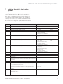
Start-up checklist
Proceed in accordance with the following checklist during start-up. A description of the individual steps can be
obtained from the following sections.
The casing must be removed from the boiler before
start-up.
• To do this, unscrew the screw above the multi-function operating panel.
• Pull the casing top forward.
• Lastly, remove the side sections.
22
Installation and maintenance instructions ecoCRAFT - 0020055744_03
Start-up 6
No.
Procedure
Remarks
Tools required
1
Check the gas connection pressure
Minimum inlet working pressure is not less than
17 mbar
U-tube or digital pressure gauge
2
Check whether syphon is full
If necessary fill via flue gas analysis point
3
Check electrical connection rail
Mains connection: L,N, PE terminals
Controller terminals: "Bus", /7-8-9 or 3-4
4
Switch unit on, display active
Otherwise check fuses
6
Activate chimney sweep function
Press "+" and "-" buttons simultaneously
7
Check the entire gas route for leaks
Leak seeking spray or a gas sensing instrument
is recommended (especially for checking the
burner gaskets for leaks). If necessary tighten
the burner gasket to 12 Nm).
Gas sensing equipment
8
Measuring the flue draught
The maximum draught must not exceed
20 mbar.
If the draught is too great the flue draught must
be reduced by suitable measures.
Measuring unit for flue draught
9
CO2 measurement
Target value:
at rated load: 9.3 % Vol. (±0.2 % Vol.)
at minimum load: 9.0 %Vol. (±0.2 % Vol.)
CO2-measuring instrument
10
If CO2 not within tolerance:
Adjust CO2, see Section 6.5.3
11
After setting gas ratio, activate chimney
sweep function then perform repeat CO2
measurement
Target value:
at rated load: 9.3 % Vol. (±0.2 % Vol.)
at minimum load: 9.0 % Vol. (±0.2 % Vol.)
12
CO measurement (target< 80 ppm)
13
Check condensate trough, syphon and
condensate drain for leaks
14
Switch boiler off and on again
Safe exit from the Test Mode and Reset
15
Programme heating regulator with
customer and check user water/heating
Hand the operating instructions for the
regulator to the customer
16
Affix sticker 835593 "Read Operating
Instructions" in user's language to the
front of the unit
CO2-measuring instrument
CO measuring instrument
Visual check or additional check of each seal
position with CO-measuring instruments
Table 6.1 Start-up checklist
Installation and maintenance instructions ecoCRAFT - 0020055744_03
23
6 Start-up
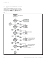
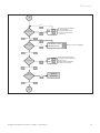
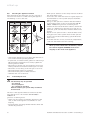
6.3
Function menu (for maintenance and service
work)
The function menu allows the technician to perform
functional checks on individual actuators. It can always
be started after a "RESET" or a "Mains ON". After a
wait of approx. five seconds or if the "-" button is
pressed, the unit's electronics switch to normal operation.
3
Start
After reset
After mains "ON"
Activate
function menu
No
End,
normal
operation starting
Yes
Back
Check
internal pump?
Yes
On
Off
Back / Forward
Back
Check fan?
Yes
On
Off
Blower started
at max. speed.
On
Off
All connections designated
as cylinder charging pump
are supplied with 230 V.
- 2 from 7 module, if d.27
or d.28 = 3.
On
Off
All connections designated
as circulation pump
are supplied with 230 V.
- PCB, if d.26 = 1.
- 2 from 7 module, if d.27
or d.28 = 3.
Back / Forward
Back
Check
charging pump?
Yes
Back / Forward
Back
Check
circulation pump?
Yes
Back / Forward
2
Fig. 6.1 Function menu (continued on next page)
24
Installation and maintenance instructions ecoCRAFT - 0020055744_03
Start-up 6
2
Back
Check
external pump?
Yes
On
Off
All connections designated
as external pump
are supplied with 230 V.
- 2 from 7 module, if d.27
or d.28 = 2.
Back / Forward
Back
Vent hydraulics?
Yes
Hot water circuit
Heating circuit
Water pressure is displayed.
Back / Forward
Test burner?
Yes
On
Off
The internal heating pump
is energised at the same time
as the burner;
function menu terminated.
VT Target = VL max ºC
Back / Forward
Check
circulation pump?
Yes
Normal
operation
Back / Forward
3
Fig. 6.1 Function menu (continued)
Installation and maintenance instructions ecoCRAFT - 0020055744_03
25
6 Start-up
6.4
Filling the system
• Flush the entire heating system thoroughly before filling.
6.4.2 Filling the siphon
• Fill the siphon with water through the opening in the
flue gas collector.
Corrosion protection by water treatment
In the case of heating water that has been conditioned
by the addition of strongly alkaline substances, aluminium and its alloys are at risk from corrosion.
The pH of the heating water must not exceed a value
of 8.5.
Danger!
d Risk
of poisoning from leaking flue gas!
6.4.1 Filling the heating side
• Release the cap on the customer side automatic air
vent by one or two turns. Make sure that the opening
of the cap does not point towards the electronic components.
• Fill the installation up to a system pressure of 2.3 to
2.5 bar. The current water pressure will be displayed if
the "-" button is pressed for approx. 3 seconds.
• Fill the installation via the boiler filling and draining
device provided on the installation.
• Close the bleed nipple.
• Bleed the radiators.
• Read the pressure again on the pressure gauge. If the
installation pressure has fallen, the installation should
be filled up again and vented once again.
• Check all connections and the entire system for leaks.
You can use the P0 test program to bleed the heating
circuit, the boiler and, if necessary, the cylinder.
• To do this, keep the "+" button pressed for approx
5 seconds while switching on the mains.
• Select P0 with the "+" or "-" buttons.
• Start the program with the "i" button.
• Step forward to the cylinder charging circuit by pressing again.
26
If the device is operated with an empty
condensate siphon, there is a risk of poisoning
from the escaping flue gases. Be absolutely
certain, therefore, to fill the siphon before
starting up.
6.5
Checking the gas setting
The unit is set to the values quoted in Chapter 12 "Specifications" in the factory. In some areas these settings
may need to be adjusted at the installation site.
To ensure proper functioning of the combined gas/air
controller, the O2-/CO2 concentration in the flue gas (see
Section 6.5.2) and also the gas pressure ahead of the
gas valve (see Section 6.5.1) must be measured.
The checking and setting is carried out at both the rated
and the minimum loading.
Caution!
a Before start-up of the unit compare the details
concerning the set type of gas on the
identification plate with the type of gas supply
at the installation site.
It is not necessary to check the quantity of
gas. The adjustment takes place on the basis of
the CO2 component in the flue gas.
The appliances are delivered as Natural Gas G20 variants.
Installation and maintenance instructions ecoCRAFT - 0020055744_03
Start-up 6
6.5.1
Checking the connection pressure
(Gas flow pressure)
1
Caution!
a Risk
of measurement errors caused by the in-
gress of leakage air!
Make sure that the opening for the measuring
probe is well sealed during the measurement to
prevent the ingress of leakage air!
Note!
h The maximum draught must not exceed
20 mbar, as otherwise the results of the CO2
measurement will be invalid. If necessary you
can remove the cover of the inspection opening
in the external flue gas ducting during the
measurement and then replace it after the
measurement.
Fig. 6.2 Checking the gas flow pressure
Key
1 Pressure measurement nipple
Proceed as follows to check the connection pressure:
• Remove the unit's front casing.
• Lift the front cover.
• Unfasten the screw on the pressure measurement nipple (1) ahead of the gas valve.
• Connect a pressure gauge.
• Start up the unit.
• Switch the unit to maximum output in Test Mode; select "Chimney sweep" operating state by pressing "+"
and "-" simultaneously.
• Measure the connection pressure in comparison with
atmospheric pressure. The measured pressure must
be not less than 17mbar.
Note!
Note regarding the test programs:
The Test Mode is automatically exited after
15 minutes. If you have not been able to complete the measurement in this time period, the
Test Mode must be re-activated.
Testing at rated load
• Start the "P1" test program for rated output.
• Press and hold the "+" button.
• Press the "Fault resolution" button.
• Hold the "+" button until "P0" appears.
• Switch to "P1" with the "+" button.
• Start the test program by pressing the "i" button.
After a stabilising period of one minute, the boiler is run
at its rated output.
Caution!
a If the connection pressure (gas flow pressure)
is not less than 17mbar, no adjustment should
be undertaken, and the unit must not be
started up!
In this case proceed as follows:
• Take the appliance out of operation.
• Remove the pressure gauge and tighten the screw on
the pressure measuring nipple (1) again.
If you cannot rectify the fault, do not start up the unit
and inform the gas supply company.
Caution!
a Malfunction!
The combustion air must be free of particles or
the burner can be contaminated with dirt.
Take particular care that no building dust or
fibres of insulating material are present in the
combustion air.
6.5.2 Checking the CO2 content
The opening for the CO2 measurement must be made in
the customer side of the flue pipe.
Installation and maintenance instructions ecoCRAFT - 0020055744_03
27
6 Start-up
• Measure the CO2 content in the flue gas.
VKK GB xx6/3-E-H
% CO2
at rated load
% CO2
at minimum load
G20
20 mbar
9.3 ± 0.2
9.0 ± 0.2
Table 6.2 CO2 target values for rated and minimum load
No further adjustment is required if the measurement
corresponds with the relevant value in the table. If the
measured CO2 content lies outside this range, adjustment of the gas/air mixture is required.
h Note!
The maximum draught must not exceed
20 mbar, as otherwise the results of the CO2
measurement will be invalid. If necessary you
can remove the cover of the inspection opening
in the external flue gas ducting during the
measurement and then replace it after the
measurement.
CO2 adjustment at rated load
The gas ratio setting for the rated load is made by
means of the gas flow rate screw (1), using an Allen key
from the gas valve. You will find a 3 mm Allen key under
the cover.
Testing at minimum load
• Start the test program "P2" for minimum load (as described above).
• Measuring the CO2 content in the flue gas.
No further adjustment is required if the measurement
corresponds with the relevant value in the table (see
Table 6.2). If the measured CO2 content lies outside this
range, adjustment of the gas/air mixture is required.
1
To end the test, proceed as follows:
• Turn the boiler off.
• Close the measurement opening and the pressure
measuring nipple.
• Check them for leaks.
Fig. 6.3 Gas flow rate screw
6.5.3
Setting the CO2 content
Gas/air mixture adjustment
The gas ratio setting must be carried out in the sequence given. The gas/air mixture is factory set for natural gas E (G20).
h Note!
The Test Mode is automatically exited after
15 minutes. If you have not been able to complete the measurement in this time period, the
Test Mode must be re-activated.
• Pass the measuring probe for the flue gas measuring
instrument into the measurement opening.
• Remove the cover cap from the gas valve.
Proceed as follows to start test program "P1" for the
rated load:
• Press and hold the "+" button.
• Press the "Fault resolution" button.
• Hold the "+" button until "P0" appears.
• Switch to "P1" with the "+" button.
• Start the test program by pressing the "i" button.
After a stabilising period of one minute, the boiler is run
at its rated output.
• Determine the CO2 content at full load and compare
this value with the values in Table 6.2.
• If necessary, correct the CO2 content with the gas flow
rate screw (1) according to Table 6.2, using a 3 mm
Allen key.
• To reduce the CO2 content, turn the Allen key in a
clockwise direction (right).
• To increase the CO2 content, turn the Allen key in an
anti-clockwise direction (left).
28
Installation and maintenance instructions ecoCRAFT - 0020055744_03
Start-up 6
h Note!
h Note!
Adjust only in increments of 1/8 turn and wait
Adjust only in increments of 1/8 turn and wait
approx. 1 minute after each adjustment until
the value stabilises.
approx. 1 minute after each adjustment until
the value stabilises.
After the adjustment, check the quality of combustion
through the display opening:
— no lifting of the flame evident
— no glowing of the burner surface
• To increase the CO2 content, turn the zero point screw
in a clockwise direction (right).
• To reduce the CO2 content, turn the zero point screw
in an anti-clockwise direction (left).
• Terminate the "P1" test program.
• Fit the cover cap on the gas valve.
After the adjustment, check the quality of combustion
through the display opening:
— no lifting of the flame evident
— no glowing of the burner surface
Adjustment at minimum load
Note!
h Before making any adjustment, first perform
• Terminate the "P2" test program.
• Fit the cover cap on the gas valve.
a CO2 measurement, as the adjustment at the
rated load also changes the minimum load
accordingly. An adjustment of the minimum
load is only required in exceptional cases
1
Fig. 6.4 Zero point screw
The gas ratio setting for minimum load is made by
means of the zero point screw (1) (Torx Tx40 under the
cover) on the gas valve.
• Remove the cover cap for the zero point screw (1) on
the gas valve.
• Start the test program "P2" for minimum load (as described above).
• Determine the CO2 content at minimum load and compare this value with the values in Table 6.2.
• If necessary, correct the CO2 content with the zero
point screw on the gas combination valve according to
Table 6.2 using a Torx Tx40 driver.
h Note!
The adjustment is very sensitive. A half turn
(180°) produces a change in CO2 concentration
of approx. 1.0 %Vol.
Installation and maintenance instructions ecoCRAFT - 0020055744_03
29
6 Start-up
6.6
Checking the appliance function
After installation and setting the gas ratio, perform a
functional check before commissioning the appliance
and handing it over to the user.
• Draw special attention to the safety instructions which
the owner must follow.
• Point out to the owner the need for regular inspection
and maintenance of the system (inspection/maintenance contract).
• Bring it to the operator's attention that the manuals
should remain in the vicinity of the Vaillant VKK GB
806/3 -2806/3-E-H gas-fired condensing boiler.
• Instruct the user about measures taken to ensure the
supply of combustion air and removal of flue gas. In
particular, point out that these measures must not be
altered.
• Explain to the operator how to check the water level/
filling pressure of the system and show the operator
how to refill and bleed the heating system when the
need arises.
• Show the user the correct (economical) temperature,
controller and thermostat valve settings.
Note
h When you have finished the installation, attach
the sticker supplied (835593) in the user’s
language to the front of the appliance.
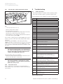
Fig. 6.5 Visual inspection of the appliance and the system
• Start up the appliance in accordance with the instructions in the relevant operating manual.
• In particular, check the burner gasket for leaks using a
CO2 measuring instrument. If necessary tighten the
burner gasket to 12 Nm.
• Check the gas infeed, flue gas installation, boiler and
heating installation and the hot water pipes for leaks.
• Check the correct fitting of the flue gas accessories.
• Check the burner flame for regularity.
• Check the heating and hot water function.
• Hand the unit over to the user.
6.7
Instructing the user
Caution!
a The
unit may only be operated
- for start-up
- for test purposes
- for continuous operation
with the air/flue gas system fully assembled
and enclosed.
The user of the appliance must be trained in the handling and function of his Vaillant VKK GB 806/3 2806/3-E-H
gas-fired condensing boiler.
• Hand over any instruction manuals intended for the
user, as well as the appliance documents for safe
keeping.
• Go through the operating manual with the owner and
answer any questions.
30
Installation and maintenance instructions ecoCRAFT - 0020055744_03
Adapting the unit to the heating system 7
7
Adapting the unit to the heating
system
The adaptation of the boiler to the heating installation is
carried out in the Diagnostic Mode. The operating concept for the selection of the various parameters and
their setting is shown in Section 6.2. Some settings are
only intended for the heating engineer and can only be
called up after service code "17" has been entered at diagnostic point 97.
An overview of the diagnostic points that can be set can
be found in Table 7.1.
Diagnostic
point
Description
Setting range
Default setting
d. 0
Heating minimum load
Settable values in kW
Maximum output
in heating mode
d. 1
Water pump overrun time for heating mode
2 - 60 min
5 mins
d. 2
Maximum burner block time at 20 °C
2 - 60 min
20 min
d.17
Changeover from flow temperature regulation
0 = flow temperature regulation
1 = return temperature
regulation (e.g. for underfloor
heating)
0
d.18
Pump run-on mode
1 = comfort
3 = eco
1 = comfort
d.20
Maximum setting value of cylinder target temp. potentiometer
50 °C - 70 °C
65 °C
d.27
Switching of accessory relay 1 on the VR40 accessory
1 = circulation pump
2 = ext. pump
3 = cylinder charging pump
4 = flue non-return valve/
extractor hood
5 = external gas valve
6 = External error message
1 = circulation
pump
d.28
Switching of accessory relay 2 on the VR40 accessory
1 = circulation pump
2 = ext.pump
3 = cylinder charging pump
4 = flue non-return valve/
extractor hood
5 = external gas valve
6 = External error message
2 = ext.pump
d.54
Switch-on hysteresis relative to the current target value
0...-10 K
-2 K
d.55
Switch-off hysteresis
0 ... 10 K
6K
d.71
Maximum target value that can be set for the heating flow
temperature
40 °C - 85 °C
75 °C
d.72
Pump overrun after charging of a consumption water storage
tank controlled by the electronics (also warm start and charging
via C1/C2)
0 - 600 s
300 s
d.75
Maximum charging time for a storage without own controller
20 - 90 min
45 mins
d.77
Cylinder minimum load (cylinder charging output limiting) in kW
Settable values in kW
max. output
d.78
Cylinder charging temperature limiting (flow target temperature
in cylinder charging mode) in °C
75 °C - 85 °C
80 °C
d.84
Number of hours until the next maintenance activity (entry of
operating hours until the maintenance alert appears in the
display)
0 ... 3000 operating hours
"-" for off
"-" for off
d.87
Gas type setting
0 = natural gas 20 mbar
0
d.98
Option to enter telephone number that is displayed with a
maintenance alert
d.99
Selection of display language
English
Table 7.1 Settable diagnostic points
Installation and maintenance instructions ecoCRAFT - 0020055744_03
31
7 Adapting the unit to the heating system
8 Maintenance
7.1
Setting the maximum boiler flow temperature
The maximum boiler flow temperature for heating mode
can be set at diagnostic point d.71, and for cylinder
charging mode at d.78 (see Table 9.2).
7.2
Setting pump overrun time
The overrun time of the boiler circulation pump can be
set at diagnostic point d.1. The overrun time for a cylinder charging pump directly connected to the boiler can
be set under Parameter d.72 if necessary. However if
the cylinder charging pump is connected to a
VRC 630, the setting must be carried out there (see
Table 7.1).
7.3
Blocking time and heating partial load
The maximum burner anti-cycling time in heating mode
can be set at d.2, the heating partial load at d.0 and the
cylinder charging minimum load at d.77 (see Table 9.2).
7.4 Start-up behaviour
When there is a heat requirement, the boiler goes to
Status "S.2" (pump pre-run)for approx. 15 seconds and
then the fan is started ("S.3").
After the pressure cartridge is switched in and the start
speed has been reached, the gas valve is opened and
the burner started (Status "S.4").
The boiler is now operated for 60 seconds at minimum
output and then, depending on the deviation from the
target value, the calculated target value for the speed is
set.
8
Maintenance
8.1
General notes
Permanent operational readiness, safety, reliability and
a long service life require inspections and maintenance
work to be carried out regularly every year by a heating
engineer. We recommend making a maintenance agreement.
Danger!
d Inspection,
maintenance and repair work should
only be undertaken by an approved heating
installation company.
Inspections/Maintenance work not carried out
can result in damage to property and personal
injury.
To ensure all the functions of your Vaillant appliance on
a continuing basis and in order not to change the
approved original condition, only original Vaillant replacement parts may be used for service and maintenance work!
Any replacement parts which might be required are listed in the relevant current replacement part catalogues.
Information can be obtained from Vaillant Customer
Service Centres.
32
8.2
Safety instructions
Always perform the following steps prior to inspection
work:
h Note!
If inspection and maintenance work is
necessary with the mains switch on, this is
indicated in the description of the maintenance
work.
• Switch off the mains switch.
• Close the gas isolator valve.
• Close the heating flow and return.
Danger!
e Danger
of death from electric shock!
The supply terminals of the device are under
voltage even if the main switch is off. Before
working on the appliance, turn off the power
supply and secure it against being switched on
again!
8.3
Operating hours indication
The burner operating hours are displayed here:
- Diagnostic point d.81 for cylinder charging mode
- Diagnostic point d.82 for heating mode
8.4
Chimney sweeper operation
For the emissions measurement by the chimney sweep,
and for other measurements, it may be necessary to run
the boiler at maximum output for an extended period of
time. For this reason there is a chimney sweep operation mode.
• To this end, press the "-" and "+" buttons simultaneously.
The boiler will now run at maximum capacity for 15 minutes.
By pressing "+" and "-" simultaneously once more,
the function can be terminated before this time has expired. The function is automatically terminated after a
flow temperature of 85 °C has been reached (overtemperature protection).
8.5
Maintenance checklist
In the framework of the inspection work, check the
points listed here and perform the relevant maintenance
work in accordance with the following chapters if necessary.
The casing must be removed from the boiler before any
maintenance work.
• To do this, unscrew the screw above the multi-function operating panel.
• Pull off the front cover.
• Remove the top and side sections as required.
Installation and maintenance instructions ecoCRAFT - 0020055744_03
Maintenance 8
No.
Procedure
Remarks
Top up if necessary (approx. 2.5 bar)
2
Check the filling pressure of the heating system
(button "-")
Visual check for leaks in heating circuit
3
Visual check of safety valve
In accordance with BS 6644
4
Check condensate collector, siphon, supply air and flue See: 8.5 and 8.6
gas paths for contamination and leaks. Check gaskets
of the condensate trough, the inspection opening and
between the flue gas flange and the heat exchanger for
damage and replace if necessary.
Switch on the appliance - call up test program
P1 = rated load, P2 = minimum load
1
5
6
7
CO2 measurement (target value:
at rated load: 9.3 % Vol.
(±0.2 % Vol.)
at minimum load: 9.0 % Vol.
(±0.2 5 Vol.)
CO measurement (target value < 80 ppm)
Capacity measurement
8
Check flue gas pressure monitor, visual check of all
tubes and measuring nipples, functional check by flue
gas full block with flue gas baffle or similar equipment
9
Check syphon and condensate drain for leaks
10
Check flue gas piping for leaks
11
Replace casing components, fully assemble boiler
12
Unit off - switch unit on - check function of regulator
(hot water/heating)
Tools
Check function of quick vent system
If the values are not within this range,
you need to perform a CO2 adjustment before the
inspection can continue (see: 6.4.3)
CO2-measuring
instrument
Gas rate check
Gas sensing
If the capacity is more than 15 % below the nominal
equipment
value, then the burners must be cleaned or replaced
Every time the burner is dismantled, replace the
gaskets and tighten the burner flange to 12 Nm on the
diagonal.
After cleaning or replacing the burner, a new measurement of the CO2 value and the loading is required. If
necessary, the CO2 value will have to be re-set.
Check for gas leaks behind the fan and along all the
burner gaskets with gas sensing equipment.
At nominal capacity and full blockage the burner must
go out after latest two minutes, and then thereafter
continuous automatic re-starting. No flue gas should
escape to the installation room through the syphon.
Visual check of connection and fixing fittings. No condensate should drip out of the connection points, pipes
have a gradient of > 3° in the direction of the boiler.
Table 8.1 Inspection Checklist
8.6
Cleaning the condensate collector
• Remove the front section of the boiler casing.
• Remove the cover on the inspection opening (1).
• Check the water condensate collector for dirt contamination and clean if required with a scraper.
• Check the gasket on the inspection opening for damage before re-assembly. If required, a new gasket
should be fitted.
1
Fig. 8.1 Cleaning the condensate collector
Installation and maintenance instructions ecoCRAFT - 0020055744_03
33
8 Maintenance
8.7
Cleaning the siphon
• Remove the boiler casing.
h
8.8
Checking the flue gas pressure monitor
1
Note
Condensate can escape while the drain hoses
are being pulled off.
2
1
2
Fig. 8.4 Checking the flue gas pressure monitor
• Check the hose to the flue gas pressure monitor (2)
for contamination and correct fit.
Caution!
a The
hose must be connected to the connection
marked "P1" on the flue gas pressure monitor.
8.9
Checking the combustion air pressure monitor
• Check the hoses to the combustion air pressure monitor (1) (see Fig. 8.4) for contamination and correct fit.
Fig. 8.2 Removing the hoses
• Unfasten the hoses (1) and (2).
3
Caution!
a The
connection marked "P1" on the combustion
air pressure monitor must be connected to the
Venturi. The connection marked "P2" on the
combustion air pressure monitor must be
connected between the gas valve and the Venturi.
1
P2
P1
P2
3
Fig. 8.3 Pulling off the clip
•
•
•
•
Pull off the clip (3).
Remove the siphon and clean it.
Fit the siphon in reverse sequence.
Unscrew the plug from the flue gas measurement
opening and fill the siphon with water through this
opening.
• Close the opening on the flue gas connection with the
plug.
34
P3
P3
P1
2
4
Fig. 8.5 Connecting the combustion air pressure monitor
Key
1 Combustion air pressure monitor
2 Venturi
3 Gas valve
4 Supply air box
Installation and maintenance instructions ecoCRAFT - 0020055744_03
Maintenance 8
8.10
Cleaning the burner
If cleaning of the burner is necessary, the complete
burner/fan unit must be dismantled.
Danger!
d Danger
of personal injury and material damage!
• Blow out the burner with compressed air outside the
installation room from the slot plate towards the
metal fleece. If the burner is heavily contaminated it
must be replaced.
• Re-assemble all the components in reverse order.
1
Shut off the gas supply before dismantling the
burner, as otherwise gas can escape without
control.
7
6
1
2
Fig. 8.7 Burner guide slots
2
5
4
3
Fig. 8.6 Dismantling the burner
• Remove the front casing.
• Hinge the electronic box down.
• Unfasten the connections on the gas valve (4) and on
the fan (1).
• Unfasten the plug on the ignition electrode and the
earth cable (6).
• Unfasten the control hoses (3) on the gas valve and
on the Venturi.
• Unfasten the four screws between the Venturi and the
supply air silencer or HT pipe (2).
• Lay the supply air silencer with 87° HT elbow carefully to one side.
• Unfasten the four M5 screws (5) on the gas pipe (gas
filter)/gas valve.
• Unfasten the four M8 nuts (7) on the heat exchanger.
• Withdraw the entire unit, consisting of manifold
flange, fan, Venturi and gas valve, to the front and lay
it carefully to one side.
• Remove the gasket between the heat exchanger and
the manifold flange.
• Carefully withdraw the burner to the front.
Caution!
a Risk
of damage to the burner surface!
Take care that the burner surface does not get
damaged during cleaning!
Installation and maintenance instructions ecoCRAFT - 0020055744_03
Fig. 8.8 Front plate
Note!
h When inserting the burner, take care that it is
seated in the rear guide slots (1) in the heat exchanger and the front plate (2) is flush with the
heat exchanger.
h Note!
Tighten the screws on the manifold evenly to 12 Nm.
• Open the gas valve and check for leaks up to the gas
valve.
• Switch on the boiler.
• Use a gas sensing instrument to check for leaks in the
gas/air combination behind the gas valve and along
the burner gaskets.
• Tighten the screws to 12 Nm if necessary.
35
8 Maintenance
9 Troubleshooting
8.11
9
Checking the safety temperature limiter
1
Troubleshooting
9.1
Status messages
• Press the "i" button to read the current operating status.
• Press the "i" button again to quit the display mode.
All the parameters are summarised in the following table.
Display
Status messages
Heating mode
Fig. 8.9 Reset button
Key
1 STL reset button with cover cap
• Switch on the mains switch.
• Turn the heating circuit off.
• Set the unit to maximum feed temperature and heat
the unit up to switch-off by the controller.
• After waiting for two minutes (temperature equalisation) start test program "P.5".
As a result of starting test program "P.5", the boiler remains in operation until the safety temperature limiter
responds.
The test program "P.5" is called up by switching
"Mains on" whilst simultaneously holding the "+" button
down for 5 seconds. By pressing the "Info" button the
test program is started and the boiler is started for the
STL test.
h
Note!
The internal heating pump is not switched off
for control technological reasons. The isolation
units in the heating circuits should therefore
remain closed during the STL test.
The boiler must switch off at 110 ºC.
• Reset the safety temperature limiter after the boiler
(see Section 9.4) has cooled down.
h
Note!
The test programme is automatically exited
after 15 minutes. The test must be performed
within this time period.
8.12
Functional check
After completion of all inspection and maintenance
work, always carry out a function check as described in
Section 6.6.
S.00
No heat required
S.02
Water pump pre-run
S.03
Ignition
S.04
Burner mode
S.06
Fan overrun
S.07
Water pump overrun
S.08
Burner lockout after heating operation
S.20
Water pump pre-run
S.23
Ignition
S.24
Burner mode
S.26
Fan overrun after cylinder charging
S.27
Water pump overrun
S.28
Burner lock after recharging (cycle suppression)
Cylinder charging/Warm start
Special cases of status message
S.30
230V/24V room thermostat is blocking heating operation
S.31
Summer mode active or eBus controller/built-in timer
is blocking heating operation
S.32
Fan speed wait time (speed deviation still too great)
S.33
Pressure cartridge wait time (pressure cartridge
contact still has not closed)
S.34
Frost protection mode active
S.35
Speed ramp wait time (speed deviation during ramp-up)
S.36
Target value specification of analogue regulator < 20
°C , i.e. the external regulator is blocking the heating
operation
S.39
Contact thermostat has responded
S.40
Indicate emergency operation active; Unit runs in
restricted Vaillant assured comfort mode.
Corresponding error code alternates with status
message in display
S.41
System pressure too high on water side
S.42
- Flue non-return valve feedback is blocking burner
mode (only in connection with accessory)
- Condensate pump faulty -> demand is blocked
S.49
Siphon pressure cartridge has triggered, wait time
S.53
Appliance is within the waiting period of the operation
blocking function as a result of low water pressure
(flow-return difference too great)
S.54
Appliance is within the waiting period of the operation
blocking function as a result of low water pressure
(temperature gradient)
S.96
Return sensor test running, heating demands are blocked
S.97
Water pressure sensor test running, heating requests
are blocked
S.98
Flow and return sensor test in progress, heating
requests are blocked
Table 9.1 Status messages
36
Installation and maintenance instructions ecoCRAFT - 0020055744_03
Troubleshooting 9
9.2
Diagnostic mode
In the diagnostic mode various parameters can be read
off to allow display of the operating conditions and for
fault diagnosis.
• Press the "i" and "+" buttons simultaneously to call
up the diagnostic mode.
• Select the desired diagnostic point with the "+"
and "–" buttons.
• Press the "i" button to display the relevant value.
Display
Meaning
Setting range and default setting for settable parameters
d. 0
Heating partial load, settable values in kW
Default setting: max. output
d. 1
Water pump overrun time for heating mode
Setting range: 2,3…60 min; Default setting: 5 mins
d. 2
Maximum burner block time at 20 °C
Setting range: 2..60 min ; Default setting: 20 min
d. 4
Measurement of cylinder temperature [°C]
d. 5
Target value for flow/return temperature [°C]
Current target value, determined from potentiometer, controller,
control type….
d. 7
Cylinder target temperature
(15°C on left, after that 40 °C to d.20 (max. 70 °C)
d. 8
Room thermostat at terminal 3-4
Displayed value: 0 = opened, no heating mode; 1 = closed, heating
mode
d. 9
Flow target temperature [°C] from external
analogue regulator to terminal 7-8-9/eBus
Minimum of ext. eBus target value and terminal 7 target value
d.10
Internal water pump
1 = on, 0 = off
d.11
External water pump
1 - 100 = on, 0 = off
d.12
Cylinder charging pump
1 - 100 = on, 0 = off
d.13
Circulation pump:
1 - 100 = on, 0 = off
d.14
Setting for speed-controlled internal pump
Setting range: 0=auto, 20 .. 100 % fixed setting; Default setting: 0
d.15
Current output of speed-controlled pump in %
d.17
Control type
0 = flow regulation, 1 = return regulation;
Default setting: 0
d.18
Pump operating mode (overrun)
0 = overrun (comfort); 1 = continuing (eco);
Default setting: 0
d.20
Maximum setting value of cylinder target temp.
potentiometer
Setting range: 50 °C-70 °C;
Default setting: 65 °C
d.22
External cylinder charging, terminal C1-C2
1 = on, 0 = off
d.23
Summer/winter function: 1 = Winter, 0 = Summer
d.24
Fan monitor
0 = contact open, 1 = contact closed
d.25
Recharging/warm start enabled by warm start
clock regulator/timer: 1 = yes, 0 = no
Default: enabled
d.27
Switching of accessory relay 1 for the VR40
accessory
1 = circulation pump (default);
2 = ext. pump;
3 = cylinder charging pump
4 = flue non-return valve/extractor hood;
5 = external gas valve;
6 = external error message;
d.28
Switching of accessory relay 2 for the VR40
accessory
1 = circulation pump
2 = ext. pump (default);
3 = cylinder charging pump
4 = flue non-return valve/extractor hood;
5 = external gas valve;
6 = external error message;
d.30
Control signal for gas valves
0=off; 1=on
d.33
Target speed for fan [rpm x 10]
Table 9.2 Diagnostic values (cont'd. on next page)
Installation and maintenance instructions ecoCRAFT - 0020055744_03
37
9 Troubleshooting
Display
Meaning
d.34
Actual speed of fan [rpm x 10]
d.40
Flow temperature [°C]
d.41
Return temperature [°C]
d.43
Boiler temperature
d.44
Actual value of ionisation current
Setting range and default setting for settable parameters
d.47
Outside temperature [°C]
d.50
Offset for minimum speed in rpm/10
d.51
Offset for maximum speed in rpm/10
Setting range: -99..-0 Default setting: -45
d.54
Switch-on hysteresis
0K - 10K, default setting: -2
d.55
Switch-off hysteresis
0K - 10K, default setting: 6
d.60
Number of temperature limited shutdowns
d.61
Number of automatic firing system faults = Number of
failed ignitions in the last attempt
d.63
Number of shutdowns of the air monitoring
Setting range: 0..300 Default setting: 30
d.64
Average ignition time in seconds
d.65
Maximum ignition time in seconds
d.67
Remaining burner blocking time [min]
d.68
Number of unsuccessful ignitions in the first attempt
d.69
Number of unsuccessful ignitions in the second attempt
d.71
Maximum target value that can be set for the heating
flow temperature
Setting range: 40 °C ... 85 °C; Default setting: 75 °C
d.72
Pump overrun after charging of a consumption water
storage tank controlled by the electronics (also warm
start and charging via C1/C2)
Setting range: 0, 10, 20 ... 600 s
Default setting: 300 s
d.74
Anti-Legionella protection
0=off, 1=for activation enabled by controller
d.75
Maximum charging time for a storage without own
controller
Setting range: 20, 21, …90 min Default setting: 45 mins
d.77
Cylinder partial load (cylinder charging output limiting)
in kW
Default setting: max. output
d.78
Cylinder charging temperature limiting (flow target
temperature in cylinder charging mode) in °C
Setting range: 55 °C to 85 °C Default setting: 80 °C
d.80
Number of heating operation hours
d.81
Number of process water operating hours
d.82
Number of operating cycles in heating mode
d.83
Number of operating cycles in process water mode
d.84
Maintenance indicator: Number of hours until the next
maintenance activity
d.90
Digital controller recognised =1, not recognised = 0
(eBUS address <=10)
d.91
DCF status with connected external probe with DCF77
receiver
0: no reception; 1: reception;
2: synchronised; 3: valid
d.93
Unit variant DSN setting
Setting range 0 ... 99 (0=80kW, 1 =120kW...5 =280kW)
d.96
Default setting (resetting settable parameters to default
setting)
Setting range: 0 = off, 1 = on Default: 0
d.97
Activation of 2nd diagnostic level.
Password: 17
d.98
Telephone number on plain text display
Option for entering the telephone number to be displayed in the
event of a malfunction
d.99
Language used in plain text display
Note:
A single press of the "i" button displays the first 3 digits and a
second press the next 3 digits of the 6-digit number (burner
starts x 100).
Setting range: 0 - 3000h and "-"
Default setting: "-" (300 corresponds to 3000h)
Table 9.2 Diagnostic values (cont.)
38
Installation and maintenance instructions ecoCRAFT - 0020055744_03
Troubleshooting 9
9.3
Error messages
A malfunction is indicated on the display by an "F" followed by a number. In addition, the "crossed-out flame"
symbol is displayed.
Fault with
No. "F.."
Description
0
Open circuit in flow sensor
1
Open circuit in return sensor
Possible cause
10
Short circuit, flow sensor
11
Short circuit, return sensor
13
Short circuit, cylinder sensor
20
Safety temperature limiter has triggered
22
Water pressure too low, lack of water
Water pressure less than 0.3 bar
27
"Extraneous light"
Flame detected although gas valve is closed; electronics
fault
28
No flame at start
Gas supply missing, ignition or flame detection defective
29
No flame in operation
Fault in gas supply
30
Open circuit in boiler sensor
31
Short circuit in boiler sensor
32
Speed deviation too great; fan speed out of tolerance
33
Pressure cartridge is not switching on
34
Pressure cartridge is not switching off (when fan stops)
42
Coding resistor short circuited
Coding resistor short circuited or fault in cable harness
43
Coding resistor open circuit
Coding resistor open circuit or cable harness defective
49
eBus voltage short circuited
e.g. VRC 630/620 connected with reversed polarity or
Netdialog incorrectly connected
60
Fault with gas valve actuation +
Electronics defective
61
Fault with gas valve actuation -
Electronics defective
62
Fault with gas valve switch-off
Electronics defective or flame still detected 4 s after gas
shut off
63
EEPROM error
Electronics defective
64
ADC fault
Electronics defective or short circuit in safety-related
sensor
65
Temperature of electronics (ASIC) too high
Electronics defective
66
Electronics error
Electronics defective
70
DSN error
Electronics and display identifiers do not agree
73
Water pressure sensor fault
Pressure sensor not connected or short circuit
74
Water pressure sensor fault
Pressure sensor defective or cable open circuit
Fault in cable harness, fan fault
Table 9.3 Error messages
Installation and maintenance instructions ecoCRAFT - 0020055744_03
39
9 Troubleshooting
9.4
Resetting the interlock after switch-off by
the safety temperature limiter (STL)
h Note!
If a bridge is applied between terminals 3 and 4
and the ecoCRAFT starts up, the external
controller must be checked.
1
Boiler does not respond to a request for hot water
• Check the settings of the regulator unit.
• Check the charging pump.
• Check the setting of the cylinder target value adjuster
on the boiler controller.
9.6
Measurements on the components
Ionisation current
The ionisation current is at least 1.5 μA.
Fig. 9.1 Resetting the interlock after switch-off by the STL
If error code "F.20" is displayed, the safety
temperature limiter (STL) has automatically shut
down the boiler because the temperature is too high.
Proceed as follows to reset it:
• Remove the front cover.
• Reset the STL by pushing the pin (1).
Always troubleshoot and rectify the malfunction any
time the STL is triggered.
9.5
General notes
No indications in the display
If the boiler does not start, and there is no display in the
read-out on the control panel, the following points
should be checked:
– Electrical connection 230 V/50 Hz at the connection
plug.
– Main switch turned on?
– Check the 4 AT fuse in the boiler controller.
Danger!
e The
4 AT fuse is at 230 V. The boiler will have
to be voltage free for checking and
replacement.
Boiler does not respond to VRC 630 control unit
• Check the link between the "Bus" connections on the
controller and the boiler.
• Switch the VRC 630 off and then on again so that it
reads in the devices on the bus afresh.
Boiler does not respond to the 2 point control system
• Check on the System ProE whether the switch contact
between terminals 3 and 4 has been closed by the external controller.
40
Installation and maintenance instructions ecoCRAFT - 0020055744_03
Factory customer service/manufacturer's guarantee 10
Recycling and disposal 12
10 Factory customer service/
manufacturer's guarantee
10.1
Vaillant Service
To ensure regular servicing, it is strongly recommended
that arrangements are made for a Maintenance
Agreement. Please contact Vaillant Service Solutions
(0870 6060 777) for further details.
10.2
Vaillant warranty
Vaillant provide a full parts and labour warranty for this
appliance.
The appliance must be installed by a suitably competent
person in accordance with the Gas Safety (Installation
and Use) Regulations 1998, and the manufacturer’s instructions. In the UK ‘CORGI’ registered installers undertake the work in compliance with safe and satisfactory
standards.
All unvented domestic hot water cylinders must be installed by a competent person to the prevailing building
regulations at the time of installation (G3).
Terms and conditions apply to the warranty, details of
which can be found on the warranty registration card included with this appliance.
Failure to install and commission this appliance in compliance with the manufacturer’s instructions may invalidate the warranty (this does not affect the customer’s
statutory rights).
Installation and maintenance instructions ecoCRAFT - 0020055744_03
11
Recycling and disposal
Recycling and disposal are already taken into account
during the development of all Vaillant products. Vaillant’s standards lay down strict requirements.
The recyclability, demountability and separability of materials and components are taken into account for the
selection of materials in the same way as environmental
hazards and health risks during recycling and the disposal of unavoidable remains of unusable residue.
11.1
Appliance
The Vaillant boiler consists up to 92 % of metallic
materials which can be melted down again in steel and
smelting works and can as a result be reused almost
without limitation.
The EPS (Styropor)® EPP used for insulating the cylinder and other components can be recycled and is
CFC-free.
The plastics used are marked, so that they are ready for
sorting and unmixed separation of the materials during
recycling.
11.2
Packaging
Vaillant has reduced the transport packaging of the appliance to the necessary minimum. The potential for recycling is consistently borne in mind when selecting the
packing materials.
The high-quality cardboard packaging materials have
been in demand as secondary raw materials in the cardboard and paper industry for a long time.
EPS and EPP (polystyrene)® are used to protect the
products during transport. EPS is recyclable and
CFC-free.
Even the films and tightening bands are made of recyclable plastic.
41
12 Technical data
12 Technical data
Term
Rated heat output range for
heating
max. rated heat loading
min. rated heat loading
Units
VKK GB
VKK GB
VKK GB
VKK GB
VKK GB
VKK GB
806/3-E-H 1206/3-E-H 1606/3-E-H 2006/3-E-H 2406/3-E-H 2806/3-E-H
80/60
kW
13.6 -78.2
21.3 -113.4
26.2 -156.5
43.1 -196.8
60/40
kW
14.1 - 80.4
40/30
kW
14.7 - 84.1
47.0 -236.2
51.0 - 275.5
22.1 - 116.5
27.1 - 160.8
44.2 - 201.0
48.2 - 241.2
52.3 - 281.4
23.1 - 121.8
28.4 - 168.2
46.2 - 210.2
50.4 - 252.2
54.7 - 294.3
Hi
kW
80.0
115.9
160.0
200.0
240.0
280.0
Hs
kW
88.8
126.6
177.6
222.0
266.4
310.8
Hi
kW
14.0
22.0
27.0
44.0
48.0
52.0
Hs
kW
15.5
24.4
30.0
48.8
53.3
57.7
Category
I2H
Connection pressure
G20
mbar
Supply requirement
(15°C, 1013 mbar)
G20
m3/h
8.5
12.3
16.9
21.2
25.4
29.6
Qmin
g/s
6.3
10.0
12.2
19.9
21.7
23.5
Qmax
g/s
35.4
51.2
70.7
88.4
106.1
123.8
min.
max.
Qmin
Qmax
°C
°C
150.0
150.0
150.0
Flue gas mass rate (G20)
Exhaust temperature
(for tV/tR = 80/60 °C)
Nominal CO2 (G20/G25)
Residual delivery pressure
60 - 65
65 - 70
9.1
9.3
% by
vol.
Pa
Maximum allowable pressure
difference between combustion
air inlet and flue gas outlet
(including wind pressures)
Maximum allowable CO2-content
in the combustion air
(recirculation)
20
100.0
100.0
150.0
200
Pa
%
5
NOx class
5
NOx emission (BS EN 483)
CO emission
mg/kWh
mg/kWh
< 60
< 20
Heating
Rated efficiency (stationary)
80/60
30% efficiency
(BS EN 483)
%
97.5
98.4
%
108.4
108,2
WR star rating
****
max. flow temperature
°C
85
Adjustable flow temperature
(Factory setting 80°C)
°C
35-85
Max. operating pressure
bar
6
Boiler capacity
(without manifolds)
Nominal circulating water
volume
Pressure loss
Δt =
20K
Δt =
20K
l
5.74
8.07
10.4
12.73
15.05
17.37
m3/h
3.44
4.99
6.88
8.60
10.33
12.05
mbar
80
85
90
95
100
105
13
20
27
34
40
47
Condensate volume
40/30
l/h
Standby heat loss, heating
70 °C
%
< 0.4
Table 12.1 Technical data
42
Installation and maintenance instructions ecoCRAFT - 0020055744_03
Technical data 12
Term
Units
VKK GB
VKK GB
VKK GB
VKK GB
VKK GB
VKK GB
806/3-E-H 1206/3-E-H 1606/3-E-H 2006/3-E-H 2406/3-E-H 2806/3-E-H
Electrical equipment
Nominal voltage
V/Hz
max. elec. power consumption
W
elec. power consumption in
standby
W
230 / 50
260
260
320
320
320
320
8
Level of protection
IP 20
Fuses fitted
4 AT
Dimensions and weights
Height
mm
1285
Width
mm
695
Depth
mm
1240
1550
Assembly weight
kg
200
220
235
275
295
310
Weight when ready for
operation
kg
210
235
255
300
320
340
Heating connection
inch
R2"
Ø mm
21
Gas connection
inch
1 1/2"
Flue gas/air spigot
mm
Condensate connection
150 / 130
200 / 130
Miscellaneous
Permissible installation types
CE Registration No.(PIN)
C33,C43,C53,C63,C83,B23,B23P
CE-0063BS3986
Table 12.1 Technical data
Installation and maintenance instructions ecoCRAFT - 0020055744_03
43
0020055744_03 GB 112008