1
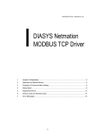
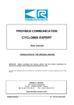
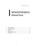
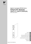
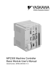
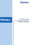
YASKAWA Electric Corporation MP Series SIO (Extension) Driver 1 System Configuration....................................................................................................... 3 2 Selection of External Device ............................................................................................ 6 3 Example of Communication Setting ................................................................................. 7 4 Setup Items ...................................................................................................................... 9 5 Cable Diagram ............................................................................................................... 14 6 Supported Device........................................................................................................... 15 7 Device Code and Address Code.................................................................................... 16 8 Error Messages.............................................................................................................. 17 1 MP Series SIO (Extension) Driver Introduction This manual describes how to connect the Display and the External Device (target PLC). In this manual, the connection procedure will be described by following the below sections: 1 System Configuration This section shows the types of External Devices which can be connected and SIO type. )"1 System Configuration" (page 3) 2 Selection of External Device Select a model (series) of the External Device to be connected and connection method. )"2 Selection of External Device" (page 6) 3 Example of Communication Settings This section shows setting examples for communicating between the Display and the External Device. )"3 Example of Communication Setting" 4 Setup Items This section describes communication setup items on the Display. Set communication settings of the Display with GP-Pro Ex or in off-line mode. )"4 Setup Items" (page 9) 5 Cable Diagram This section shows cables and adapters for connecting the Display and the External Device. )"5 Cable Diagram" (page 14) Operation GP-Pro EX Device/PLC Connection Manual 2 (page 7) MP Series SIO (Extension) Driver 1 System Configuration The system configuration in the case when the External Device of YASKAWA Electric Corporation and the Display are connected is shown. Series MP2000 CPU Link I/F MP2300 MP2200 MP2310 MP2300S SIO Type Setting Example Serial port on 218IF-01 RS232C "3.1 Setting Example 1" (page 7) " Cable Diagram 1" (page 14) Serial port on 218IF-02 RS232C "3.1 Setting Example 1" (page 7) " Cable Diagram 1" (page 14) Serial port on 260IF-01 RS232C "3.1 Setting Example 1" (page 7) " Cable Diagram 1" (page 14) Serial port on 261IF-01 RS232C "3.1 Setting Example 1" (page 7) " Cable Diagram 1" (page 14) PORT on 217IF-01 RS232C "3.1 Setting Example 1" (page 7) " Cable Diagram 1" (page 14) Connection Configuration • Cable Diagram 1:1 Connection PLC GP GP-Pro EX Device/PLC Connection Manual 3 MP Series SIO (Extension) Driver COM Port of IPC When connecting IPC with External Device, the COM port which can be used changes with series and SIO type. Please refer to the manual of IPC for details. Usable port Usable port Series RS-232C RS-422/485(4 wire) RS-422/485(2 wire) *1 PS-2000B COM1 , COM2, COM3*1, COM4 - - PS-3450A, PS-3451A COM1, COM2*1*2 COM2*1*2 COM2*1*2 PS-3650A, PS-3651A COM1*1 - - PS-3700A (Pentium®4-M) PS-3710A COM1*1 , COM2 , COM3*2 , COM4 COM3*2 COM3*2 PS-3711A COM1*1, COM2*2 COM2*2 COM2*2 PL-3000B COM1*1*2, COM2*1, COM3, COM4 COM1*1*2 COM1*1*2 *1 *1 The RI/5V can be switched. Please switch with the change switch of IPC. *2 It is necessary to set up the SIO type with the Dip switch. Please set up as follows according to SIO type to be used. Dip switch setting: RS-232C Dip switch Setting Description 1 OFF*1 2 OFF 3 OFF 4 OFF Output mode of SD (TXD) data: Always output 5 OFF Terminal resistance (220Ω) insertion to SD (TXD): None 6 OFF Terminal resistance (220Ω) insertion to RD (RXD): None 7 OFF Short-circuit of SDA (TXA) and RDA (RXA): Does not Exist 8 OFF Short-circuit of SDB (TXB) and RDB (RXB): Does not Exist 9 OFF 10 OFF Reserve (always OFF) SIO type: RS-232C RS (RTS) Auto control mode: Disable *1 It is necessary to turn ON the set value, only when using PS-3450A and PS-3451A. GP-Pro EX Device/PLC Connection Manual 4 MP Series SIO (Extension) Driver Dip switch setting: RS-422/485 (4 wire) Dip switch Setting Description 1 OFF 2 ON 3 ON 4 OFF Output mode of SD (TXD) data: Always output 5 OFF Terminal resistance (220Ω) insertion to SD (TXD): None 6 OFF Terminal resistance (220Ω) insertion to RD (RXD): None 7 OFF Short-circuit of SDA (TXA) and RDA (RXA): Does not Exist 8 OFF Short-circuit of SDB (TXB) and RDB (RXB): Does not Exist 9 OFF 10 OFF Reserve (always OFF) SIO type: RS-422/485 RS (RTS) Auto control mode: Disable Dip switch setting: RS-422/485 (2 wire) Dip switch Setting Description 1 OFF 2 ON 3 ON 4 OFF Output mode of SD (TXD) data: Always output 5 OFF Terminal resistance (220Ω) insertion to SD (TXD): None 6 OFF Terminal resistance (220Ω) insertion to RD (RXD): None 7 ON Short-circuit of SDA (TXA) and RDA (RXA): Exist 8 ON Short-circuit of SDB (TXB) and RDB (RXB): Exist 9 ON 10 ON Reserve (always OFF) SIO type: RS-422/485 RS (RTS) Auto control mode: Enable GP-Pro EX Device/PLC Connection Manual 5 MP Series SIO (Extension) Driver 2 Selection of External Device Select the External Device to be connected to the Display. Setup Items Setup Description Maker Select the maker of the External Device to be connected. Select "YASKAWA Electric Corporation". Driver Select a model (series) of the External Device to be connected and connection method. Select "MP Series SIO (Extension)". Check the External Device which can be connected in "MP Series SIO (Extension)" in system configuration. "1 System Configuration" (page 3) ) Use System Area Check this option when you synchronize the system data area of Display and the device (memory) of External Device. When synchronized, you can use the ladder program of External Device to switch the display or display the window on the display. Cf. GP-Pro EX Reference Manual "Appendix 1.4 LS Area (Direct Access Method)" This can be also set with GP-Pro EX or in off-line mode of Display. Cf. GP-Pro EX Reference Manual " 5.17.6 Setting Guide of [System Setting Window][Main Unit Settings] Settings GuideSystem Area Setting" Cf. Maintenance/Troubleshooting "2.15.1 Settings common to all Display models System Area Settings" Port Select the Display port to be connected to the External Device. GP-Pro EX Device/PLC Connection Manual 6 MP Series SIO (Extension) Driver 3 Example of Communication Setting Examples of communication settings of the Display and the External Device, recommended by Pro-face, are shown. 3.1 Setting Example 1 Settings of GP-Pro EX Communication Settings To display the setting screen, select [Device/PLC Settings] from [System setting window] in workspace. Device Setting To display the setting screen, click ([Setting]) of External Device you want to set from [Device-Specific Settings] of [Device/PLC Settings]. When you connect multiple External Device, click from [Device-Specific Settings] of [Device/PLC Settings] to add another External Device. GP-Pro EX Device/PLC Connection Manual 7 MP Series SIO (Extension) Driver Settings of External Device Communication setting of communication module by ladder software (MPE720). Please refer to the manual of external device for more detail. Ladder Software Setting 1 2 Start ladder software, make an order folder and a PLC folder in a root folder. Click the right button of the PLC which select logon in the displayed menu. • Logon after confirming that a check does not begin [online] of a displayed menu. • Refer to User's Manual of the PLC about a method of logon. 3 4 Double-click the [Definition folder]-[Module constitution] of the PLC folder, and display [Engineering Manager]. Select the rack classification and communication module, the pull-down menu in [Controller] of [Engineerring Manager]. Set the number corresponding to the slot number that a communication module uses. Select the communication module, setting contents are displayed to [Module details] of [Enginnering Manager]. 5 Double-click the number part at No. in [Module details]. Double-click the slot number connecting the ethernet unit. Setup Items Setup Description Transmission Protocol MEMOBUS Master/Slave Slave Device Address Device address of the External Device Serial I/F RS-232C Transmission Mode RTU Data Length 8Bit Parity Bit even Stop Bit 1Stop Baud Rate 19.2K Sending Disable Automatically Reception Disable 6 Double-click the "No.1", and set serial communication. Use serial communication setting to forward communication setting and the ladder program to the PLC. 7 8 9 10 11 Save setting content and finish [Engineering Manager]. DIP switch "INIT" of a communication module is ON and spend a power supply. Forward communication setting to a communication module. Logon the PLC at online and write in the data which transferred at flash memory. Power supply of PLC is OFF and DIP switch of the INIT is OFF, after spend the power supply of PLC. GP-Pro EX Device/PLC Connection Manual 8 MP Series SIO (Extension) Driver 4 Setup Items Set communication settings of the Display with GP-Pro EX or in off-line mode of the Display. The setting of each parameter must be identical to that of External Device. )"3 Example of Communication Setting" (page 7) 4.1 Setup Items in GP-Pro EX Communication Settings To display the setting screen, select [Device/PLC Settings] from [System setting window] in workspace. Setup Items Setup Description SIO Type Display the SIO type to communicate with the External Device. Speed Select speed between External Device and Display. Data Length Select data length. Parity Select how to check parity. Stop Bit Select stop bit length. Flow Control Select the communication control method to prevent overflow of transmission and reception data. Timeout Use an integer from 1 to 127 to enter the time (s) for which Display waits for the response from External Device. Retry In case of no response from the External Device, use an integer from 0 to 255 to enter how many times the Display retransmits the command. Wait To Send Use an integer from 0 to 255 to enter standby time (ms) for the Display from receiving packets to transmitting next commands. RI/VCC You can switch RI/VCC of the 9th pin when you select RS232C for SIO type. It is necessary to change RI/5V by changeover switch of IPC when connect with IPC. Please refer to the manual of the IPC for more detail. GP-Pro EX Device/PLC Connection Manual 9 MP Series SIO (Extension) Driver Device Setting Setup Items Station No. Setup Description Enter a station number of the External Device, using 1 to 63. GP-Pro EX Device/PLC Connection Manual 10 MP Series SIO (Extension) Driver 4.2 Setup Items in Off-Line Mode • Refer to the Maintenance/Troubleshooting manual for information on how to enter off-line mode or about the operation. Cf. Maintenance/Troubleshooting Manual "2.2 Off-line Mode" Communication Settings To display the setting screen, touch [Device/PLC Settings] from [Peripheral Settings] in off-line mode. Touch the External Device you want to set from the displayed list. Setup Items Setup Description Select the SIO type to communicate with the External Device. SIO Type To make the communication settings correctly, confirm the serial interface specifications of Display unit for [SIO Type]. We cannot guarantee the operation if a communication type that the serial interface does not support is specified. For details concerning the serial interface specifications, refer to the manual for Display unit. Speed Select speed between External Device and Display. Data Length Select data length. Parity Select how to check parity. Stop Bit Select stop bit length. Flow Control Select the communication control method to prevent overflow of transmission and reception data. Timeout (s) Use an integer from 1 to 127 to enter the time (s) for which Display waits for the response from External Device. Retry In case of no response from the External Device, use an integer from 0 to 255 to enter how many times the Display retransmits the command. continued to next page GP-Pro EX Device/PLC Connection Manual 11 MP Series SIO (Extension) Driver Setup Items Setup Description Wait To Send (ms) Use an integer from 0 to 255 to enter standby time (ms) for the Display from receiving packets to transmitting next commands. Device Setting To display the setting screen, touch [Device/PLC Settings] from [Peripheral Settings]. Touch the External Device you want to set from the displayed list, and touch [Device]. Setup Items Setup Description Device/PLC Name Select the External Device for device setting. Device name is a title of External Device set with GP-Pro EX.(Initial value [PLC1]) Station No. Enter a station number of the External Device, using 1 to 63. GP-Pro EX Device/PLC Connection Manual 12 MP Series SIO (Extension) Driver Option To display the setting screen, touch [Device/PLC Settings] from [Peripheral Settings]. Touch the External Device you want to set from the displayed list, and touch [Option]. Setup Items RI/VCC Setup Description You can switch RI/VCC of the 9th pin when you select RS232C for SIO type. It is necessary to change RI/5V by changeover switch of IPC when connect with IPC. Please refer to the manual of the IPC for more detail. GP-Pro EX Device/PLC Connection Manual 13 MP Series SIO (Extension) Driver 5 Cable Diagram The cable diagram shown below may be different from the cable diagram recommended by Fuji Electric Corporation. Please be assured there is no operational problem in applying the cable diagram shown in this manual. • The FG pin of the External Device body must be D-class grounded. Please refer to the manual of the External Device for more details. • SG and FG are connected inside the Display. When connecting SG to the External Device, design the system not to form short-circuit loop. • Connect the isolation unit, when communication is not stabilized under the influence of a noise etc.. Cable Diagram 1 Display (Connection Port) Cable GP (COM1) ST (COM1) IPC*1 PC/AT *1 Remarks Your own cable The cable length must be 15m or less. Only the COM port which can communicate by RS-232C can be used. COM Port of IPC (page 4) ) D-Sub 9 pin (socket) Display Shield External Device D-Sub 9 pin (plug) Pin Signal name 2 RD(RXD) 2 SD 3 SD(TXD) 3 RD 4 ER(DTR) 4 RS 5 SG 5 CS 6 DR(DSR) 7 SG 7 RS(RTS) 1 FG 8 CS(CTS) Pin Signal name Shell FG GP-Pro EX Device/PLC Connection Manual 14 MP Series SIO (Extension) Driver 6 Supported Device Range of supported device address is shown in the table below. Please note that the actually supported range of the devices varies depending on the External Device to be used. Please check the actual range in the manual of your connecting equipment. This address can be specified as system data area. *1 32 bits Device Bit Address Word Address Notes System registers SB000000 - SB08191F SW00000 - SW08191 Input registers IB00000 - IBFFFFF IW0000 - IWFFFF *1 Output registers OB00000 - OBFFFFF OW0000 - OWFFFF *1 Data registers MB000000 - MB65534F MW00000 - MW65534 As for Input and Output registers, device 0x9000-0xFFFF cannot be written. • Please refer to the GP-Pro EX Reference Manual for system data area. Cf. GP-Pro EXReference Manual "Appendix 1.4 LS Area (Direct Access Method)" • Please refer to the precautions on manual notation for icons in the table. ) "Manual Symbols and Terminology" GP-Pro EX Device/PLC Connection Manual 15 MP Series SIO (Extension) Driver 7 Device Code and Address Code Use device code and address code when you select "Device Type & Address" for the address type in data displays. Device Device Name Device Code (HEX) Address Code System registers SW/SB 0080 Word address Input registers IW/IB 0001 Word address Output registers OW/OB 0081 Word address Data registers MW/MB 0000 Word address GP-Pro EX Device/PLC Connection Manual 16 MP Series SIO (Extension) Driver 8 Error Messages Error messages are displayed on the screen of Display as follows: "No. : Device Name: Error Message (Error Occurrence Area)". Each description is shown below. Item Description No. Error No. Device Name Name of External Device where error occurs. Device name is a title of External Device set with GP-Pro EX.((Initial value [PLC1]) Error Message Displays messages related to the error which occurs. Displays IP address or device address of External Device where error occurs, or error codes received from External Device. Error Occurrence Area • IP address is displayed such as "IP address (Decimal): MAC address (Hex)". • Device address is displayed such as "Address: Device address". • Received error codes are displayed such as "Decimal [Hex]". Display Examples of Error Messages "RHAA035: PLC1: Error has been responded for device write command (Error Code: 2 [02H])" • Refer to your External Device manual for details on received error codes. • Refer to "When an error is displayed (Error Code List)" in "Maintenance/Troubleshooting Manual" for details on the error messages common to the driver. Error Code Peculiar to PLC The error code peculiar to PLC is as follows. Error code Description 0x90 Transfer error. 0x92 Illegal parameter. 0x96 Register No. over. 0x9C File is modified. 0x9D Data access error. GP-Pro EX Device/PLC Connection Manual 17 MP Series SIO (Extension) Driver Error Messages Specific to the External Device Message ID Error Message Description RHxx128 "(Node Name):PLC is busy now(Error Code: [Hex])" PLC is "Busy" RHxx129 "(Node Name):Option module is not mounted(Error Code: [Hex])" Option module not mount. RHxx130 "(Node Name):Module is not ready(Error Code: [Hex])" Module is not ready RHxx131 "(Node Name):CPU is stopped(Error Code: [Hex])" CPU is stopped RHxx132 "(Node Name): Write protected(Error Code: [Hex])" Write protected GP-Pro EX Device/PLC Connection Manual 18