1
PCI-1720
4-channel Isolated D/A
Output Card
User's manual
Copyright
This documentation and the software included with this product are
copyrighted 1999 by Advantech Co., Ltd. All rights are reserved.
Advantech Co., Ltd. reserves the right to make improvements in the
products described in this manual at any time without notice.
No part of this manual may be reproduced, copied, translated or
transmitted in any form or by any means without the prior written
permission of Advantech Co., Ltd. Information provided in this
manual is intended to be accurate and reliable. However, Advantech
Co., Ltd. assumes no responsibility for its use, nor for any infringements of the rights of third parties which may result from its use.
Acknowledgments
PC-LabCard is a trademark of Advantech Co., Ltd. IBM and PC are
trademarks of International Business Machines Corporation. MS-DOS
and Windows are trademarks of Microsoft Corporation. Intel and
Pentium are trademarks of Intel Corporation.
CE notification
The PCI-1720, developed by ADVANTECH CO., LTD., has passed the
CE test for environmental specifications when shielded cables are
used for external wiring. We recommend the use of shielded cables.
This kind of cable is available from Advantech. Please contact your
local supplier for ordering information.
On-line Technical Support
For technical support and service please visit our support website at
http:/support.advantech.com
Part No. 2003172000 1st Edition
Printed in Taiwan February 1999
Contents
CHAPTER 1 General Information ......................... 1
1.1 Introduction ......................................................... 2
1.2 Features ............................................................... 2
1.3 Applications ......................................................... 3
1.4 Specifications....................................................... 3
1.5 Block Diagram .................................................... 5
CHAPTER 2 Installation ......................................... 7
2.1 Initial Inspection ................................................. 8
2.2 Unpacking ............................................................ 8
2.3 Installation Instructions ..................................... 9
CHAPTER 3 Jumpers and I/O Connectors ........ 11
3.1 Jumper Settings ................................................ 12
3.1.1 Using jumpers to set current sink ranges .................. 12
3.1.2 Jumper JP5 Setting for the Reset State ..................... 13
3.2 Connector and pin assignments ...................... 14
3.2.1 Signal Descriptions of I/O Connector ......................... 15
CHAPTER 4 Register Structure and Format ..... 17
4.1 Overview ............................................................ 18
4.2 I/O Port Address Map ...................................... 18
4.2.1 D/A Output Channel 0 to 3 ........................................... 19
4.2.2 D/A Voltage Range and Polarity ................................... 20
4.2.3 Synchronized Output Prompt Register ....................... 21
4.2.4 Synchronized Output Control Bit ................................. 21
4.3 Unipolar and Bipolar Binary Code Tables .... 22
CHAPTER 5 Signal Connections ......................... 23
5.1 Overview ............................................................ 24
5.2 D/A Voltage Output Connections .................... 24
5.3 Current Sink Connections ............................... 25
5.4 Current Sink Load and Power Supply ........... 27
APPENDIX A Calibration ..................................... 29
A.1 Overview ........................................................... 30
A.2 Unipolar Output Calibration ........................... 31
A.3 Bipolar Output Calibration ............................. 31
A.4 Current Sink Calibration ................................ 32
CHAPTER
1
General Information
1.1 Introduction
The PCI-1720 is an isolated digital-to-analog output card for the PCI
bus. It provides four 12-bit analog output channels with isolation
protection of 2500 VDC between the outputs and the PCI bus. This is
ideal for industrial applications where high-voltage protection is
required.
Keeping the Output Settings and Values
after System Reset
Users can set the four outputs independently to different ranges: 0 to
+5 V, 0 to +10 V, ±5 V, ±10 V, 0 to 20 mA (sink) or 4 to 20 mA (sink).
When the system is hot reset (the power is not shut off), the PCI-1720
can either retain the last analog output settings and values, or return
to its default configuration based on the jumper setting. This
practical function eliminates danger caused by misoperation during
unexpected system resets.
PCI-bus Plug and Play
The PCI-1720 uses a PCI controller to interface the card to the PCI
bus. The controller fully implements the PCI bus specification Rev
2.1. All bus relative configurations, such as base address and interrupt assignment, are automatically controlled by software.
1.2 Features
* Four 12-bit D/A output channels
* Multiple output ranges
* 2500 VDC isolation between the outputs and the PCI bus
* Keeps the output settings and values after system reset
* One 37-pin D-type connector for easy wiring
2
PCI-1720 User's Manual
1.3 Applications
* Process control
* Programmable voltage source
* Programmable current sink
* Servo control
1.4 Specifications
D/A Output
* Channels: 4 isolated D/A channels
* Resolution: 12 bits
* Output ranges:
Unipolar: 0 ~ +5 V, 0 ~ +10 V
Bipolar: ±5 V, ±10 V
Current loop (sink): 0 ~ 20 mA, 4 ~ 20 mA
* Throughput: 500 kHz
* Accuracy: ±0.024%
* Isolation voltage: 2500 VDC between the outputs and the PCI bus
* Temperature drift: Typical:10 PPM/°C (0 ~ 60°C)
Maximun:20 PPM/°C (0 ~ 60°C)
* Output current: ±5 mA max.
* Current loop excitation voltage: 50 V max.
* On-board 12 VDC excitation voltage (80 mA max.)
Chapter 1 Gerneral Information
3
Power consumption
* +5 V @ 350 mA (typical), 500mA (Max.)
* +12V @ 200 mA (typical), 350mA (Max.)
Physical
* Connector: 37-pin D-type connector
* Dimensions: 175 x 100 mm (6.9" x 3.9")
Environment
* Operating temperature: 0 ~ +60°C (32 ~ 140°F)
* Storage temperature: -20 ~ +70°C (-4 ~ 158°F)
* Operating humidity: 5 ~ 95 % RH non-condensing (refer to IEC 682-3)
* MTBF: over 71,280 hrs @ 25°C, grounded, fix environment
4
PCI-1720 User's Manual
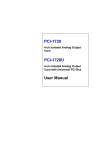
1.5 Block Diagram
P CI B U S
PCI
Controller
Data Buffer
Control
Logic
and
Decoder
Data Buffer
Isolation
2500 V DC
4 Ch
12 Bit
D/A
D/A Range
Control
Chapter 1 Gerneral Information
5
6
PCI-1720 User's Manual
CHAPTER
2
Installation
Chapter 2 Installation
7
2.1 Initial Inspection
Before installing the PCI-1720, check the card for visible damage.
We have carefully inspected the card both mechanically and electrically before shipment. It should be free of marks and in perfect order
upon receipt.
As you unpack the PCI-1720, check it for signs of shipping damage
(damaged box, scratches, dents, etc.). If it is damaged or fails to meet
specifications, notify our service department or your local sales
representative immediately. Also, call the carrier immediately and
retain the shipping carton and packing materials for inspection by the
carrier. We will then make arrangements to repair or replace the unit.
2.2 Unpacking
The PCI-1720 contains components that are sensitive and vulnerable
to static electricity. Discharge any static electricity on your body to
ground by touching the back of the system unit (grounded metal)
before you touch the board.
Remove the PCI-1720 card from its protective packaging by grasping
the card's rear panel. Handle the card only by its edges to avoid static
discharge which could damage its integrated circuits. Keep the
antistatic package. Whenever you remove the card from the PC,
protect the card by storing it in this package.
You should also avoid contact with materials that hold static electricity such as plastic, vinyl and styrofoam.
Check the product contents inside the packing. There should be one
card, one CD-ROM, and this manual. Make sure nothing is missing.
8
PCI-1720
User's Manual
2.3
Installation Instructions
The PCI-1720 can be installed in any PCI slot in the computer.
However, refer to the computer user's manual to avoid any mistakes and danger before you follow the installation procedure
below:
1. Turn off your computer and any accessories connected to the
computer.
Warning! TURN OFF your computer power supply whenever
you install or remove any card, or connect and
disconnect cables.
2. Disconnect the power cord and any other cables from the back
of the computer.
3. Remove the cover of the computer.
4. Select an empty 5 V PCI slot. Remove the screw that secures the
expansion slot cover to the system unit. Save the screw to
secure the interface card retaining bracket.
5. Carefully grasp the upper edge of the PCI-1720. Align the hole in
the retaining bracket with the hole on the expansion slot and align
the gold striped edge connector with the expansion slot socket.
Press the card into the socket gently but firmly. Make sure the card
fits the slot tightly.
6. Secure the PCI-1720 by screwing the mounting bracket to the back
panel of the computer.
7. Attach any accessories (37-pin D type cable, wiring terminal,
etc.) to the card.
8. Replace the cover of your computer. Connect the cables you
removed in step 2.
9. Turn the computer power on.
Chapter 2 Installation
9
10
PCI-1720
User's Manual
CHAPTER
3
Jumpers and
I/O Connectors
The PCI-1720 is a “plug-and-play” card, i.e. the system BIOS assigns
the system resources such as the base address and the interrupt
number automatically. There are only 2 functions with 5 jumpers to
configure to your applications requirements. The following sections
offer the necessary information for setting the PCI-1720’s jumpers.
You may need to refer to the figure below for help in identifying
jumper locations.
Figure 3-1: PCI-1720 jumper locations
3.1 Jumper Settings
3.1.1 Using jumpers to set current sink
ranges
Jumpers JP1 to JP4 are used to select each channel’s current sink
range, either 4 ~ 20 mA or 0 ~ 20 mA. Jumpers JP1 to JP4 correspond
with D/A channel 0 to channel 3 respectively. In order to use the
current sink range, you have to set the PCI-1720 output voltage range
to 0 ~ 5 V. The figure below shows the correct jumper settings for the
PCI-1720’s current sink range.
12
PCI-1720 User's Manual
JP1 to JP4
0 ~ 20 m A
4 ~ 20 m A
Figure 3-2: Jumper settings for PCI-1720’s current sink range
Note!:
In order to maintain accurate outputs for your field
applications, it is important that you calibrate the PCI1720’s variable resistors (VRs) from time to time.
Calibration instructions are provided in Appendix A.
3.1.2 Jumper JP5 Setting for the Reset State
Jumper JP5 gives the PCI-1720 a new and valuable capability. With
JP5 enabled, the PCI-1720 “memorizes” all D/A output settings and
output values, and, in the event of a “hot” reset, i.e., the power is not
shut off, the settings and output values present at each channel just
prior to reset are still maintained. This feature is very useful for user’s
field applications. For example, it may allow a computer be “hot”
reset without requiring the whole control system to shutdown. (Since
output values are left unchanged.)
Complete loss of power to the card clears all settings and output
values even if JP5 is enabled; i.e. if the power to the card is disconnected, the card’s initial power-on state will be the default state. The
default state is the output range for all channels is 0 ~ 5 V and all the
output values are 0 V.
Chapter 3 Jumpers and I/O Connector
13
When jumper JP5 is disabled, power-off or “hot” reset results in
outputs returning to their default state.
JP5
K e e p s la s t s ta tu s a fte r re s e t
L o a d s d e fa u lt w h ile re s e t
Figure 3-3: Jumper JP5 setting for the reset state
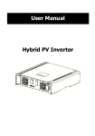
3.2 Connector and pin assignments
The PCI-1720 uses one DB-37 female connector, which is located on
the card at CN1 (see Figure 3-1) and connects D/A signals to external
devices. The following figure shows the pin assignments of the
connector.
NC
1
+1 2 Vo u t
2
A GND
3
A GND
4
Vo u t 0
5
A GND
NC
21
NC
22
NC
23
NC
24
NC
25
NC
26
NC
27
NC
28
NC
29
NC
30
NC
31
NC
32
NC
33
NC
34
NC
35
NC
36
NC
37
NC
6
Is in k 0
7
Vo u t 1
8
A GND
9
Is in k 1
10
Vo u t 2
11
A GND
12
Is in k 2
13
Vo u t 3
14
A GND
15
Is in k 3
16
NC
20
17
NC
18
NC
19
Figure 3-4: PCI-1720 pin assignments
14
PCI-1720 User's Manual
3.2.1 Signal Descriptions of I/O Connector
Signal Name Reference Direction
Description
VOUT<0...3>
AGND
Output
Analog Voltage Output Channels 0 through 3.
These pins supply the voltage outputs for the
analog outputs.
ISINK <0...3>
AGND
Input
Current Sink Channels 0 through 3.
These pins provide the current loop sink input.
+12 VOUT
AGND
Output
+12 VDC Source. This pin is a +12 VDC power
supply (80mA max.) for current loop exciting
voltage.
AGND
-
-
Analog Ground. The analog output voltage
and +12 VDC source are referenced to these
pins.
NC
-
-
No Connection to pin
Chapter 3 Jumpers and I/O Connector
15
16
PCI-1720 User's Manual
CHAPTER
4
Register Structure
and Format
4.1 Overview
The PCI-1720 is delivered with an easy-to-use 32-bit DLL driver for
user programming under the Windows 95/98/NT operating system.
We advise users to program the PCI-1720 using the 32-bit DLL driver
provided by Advantech to avoid the complexity of low-level programming by register.
The most important consideration in programming the PCI-1720 card
at a register level is to understand the function of the card’s registers.
The information in the following sections is provided only for users
who would like to do their own low-level programming.
4.2 I/O Port Address Map
The PCI-1720 requires 10 addresses in the PC’s I/O space. The
address of each register is specified as an offset from the card’s base
address. For example, BASE + 0 is the card’s base address and BASE
+ 7 is the base address plus seven bytes.
Table 4-1 shows the function of each register and its address relative
to the card’s base address.
18
PCI-1720 User's Manual
Table 4-1: PCI-1720 register format and function description
Base
Address
+ decimal
7
6
5
4
+0
D7
D6
D5
D4
Data
+1
+2
D7
D6
D5
+4
D7
D6
D5
+6
D7
D6
D5
0
D2
D1
D0
D10
D9
D8
D3
D2
D1
D0
D11
D10
D9
D8
D3
D2
D1
D0
D11
D10
D9
D8
D4
+7
1
D3
D4
+5
2
D11
D4
+3
Function description R/W
3
D3
D2
D1
D0
D11
D10
D9
D8
D/A output channel 0
W
D/A output channel 1
W
D/A output channel 2
W
D/A output channel 3
W
DA3_ DA3_ DA2_ DA2_ DA1_ DA1_ DA0_ DA0_ D/A voltage range
U/B 5/10 U/B 5/10 U/B 5/10 U/B 5/10 and polarity
+8
+9
+15
SC0
R/W
Synchronized output
prompt register
W
Synchronized output
control bit
R/W
* "R" means readable and "W" means writable
4.2.1 D/A Output Channel 0 to 3
The write-only registers of BASE + 2(n) and BASE + (2(n) + 1) accept
data for D/A output channel n (n = 0, 1, 2, 3).
Table 4-2: Register for D/A data
Base
Address
+ decimal
7
6
5
4
+2(n)
D7
D6
D5
D4
+(2(n)+1)
Data
Function description R/W
3
2
1
0
D3
D2
D1
D0
D11
D10
D9
D8
D/A output channel n
Chapter 4 Register Structure and Format
W
19
D11 ~ D0
Digital to Analog data
D0 is the LSB (Least Significant Bit) and D11 is the MSB (Most
Significant Bit) of the D/A data.
Note!:
To write D/A data, write the low byte first, then write
the high byte.
4.2.2 D/A Voltage Range and Polarity
The read-writable register of BASE + 8 allows users to set the D/A
voltage range and polarity.
Table 4-3: Register for D/A voltage range and polarity
Base
Address
+ decimal
+8
Data
7
6
5
4
Function description R/W
3
2
1
0
DA3_ DA3_ DA2_ DA2_ DA1_ DA1_ DA0_ DA0_ D/A voltage range
U/B 5/10 U/B 5/10 U/B 5/10 U/B 5/10 and polarity
Table 4-4: Output range of D/A channel n
DAn_U/B
DAn_5/10
D/A channel n output range
0
0
0 to +5 V
0
1
0 to +10 V
1
0
-5 to +5 V
1
1
-10 to +10
* n = 0,1,2,3.
20
PCI-1720 User's Manual
R/W
4.2.3 Synchronized Output Prompt Register
During normal operation, the PCI-1720 will accept digital values one
at a time from the host PC, convert these values to analog values, and
immediately output these analog values from the channels directed
by the host PC.
However, the PCI-1720 has the capability to store each analog value
in its proper channel buffer as it is generated, then simultaneously
output one analog value from each of its four channels on receipt of a
synchronizing character. Any character can act as a synchronizing
character, but it must be written to the BASE + 9 register to prompt
synchronized output.
4.2.4 Synchronized Output Control Bit
Table 4-5: Synchronized output control bit
Base
Address
+ decimal
+15
Data
7
6
5
4
Function description R/W
3
2
1
0
SC0
Synchronized output
control bit
R/W
The register BASE + 15 stores the synchronized output control bit.
When the SC0 bit is set to 1, the synchronized data output function is
enabled and analog values will not be output until a character is
written to the BASE + 9 register. When the SC0 bit is set to 0, the
synchronized data output function is disabled. Analog data output
occurs as soon as an output channel receives an element of output
data.
Chapter 4 Register Structure and Format
21
4.3 Unipolar and Bipolar Binary Code
Tables
Table 4-6: Unipolar binary code table
Digital Input Code
MSB
LSB
Examples of Analog Output Voltage
1111
1111
1111
Vref (4095/4096)
1000
0000
0001
Vref (2049/4096)
1000
0000
0000
Vref (2048/4096)
0111
1111
1111
Vref (2047/4096)
0000
0000
0001
Vref (1/4096)
0000
0000
0000
Vref (0/4096)
Notes:
1. Vref is the reference source voltage that you selected. Vref is +5 V or +10 V.
2. Nominal full scale is given by FS = Vref ( (4095/
4096).
3. Nominal LSB magnitude is given by LSB = Vref ( (1/
4096).
Table 4-7: Bipolar binary code table
Digital Input Code
MSB
LSB
Examples of Analog Output Voltage
1111
1111
1111
Vref ( (2047/2048)
1000
0000
0001
Vref ( (1/2048)
1000
0000
0000
0
0111
1111
1111
-Vref ( (1/2048)
0000
0000
0001
-Vref ( (2047/2048)
0000
0000
0000
-Vref ( (2048/2048)
Notes:
1. Vref is the reference source voltage that you selected. Vref is +5 V or +10 V.
2. Nominal full scale is given by FS = Vref ( (2047/
2048).
3. Nominal LSB magnitude is given by LSB = Vref ( (1/
2048).
22
PCI-1720 User's Manual
CHAPTER
5
Signal Connections
5.1 Overview
Making correct signal corrections is important for accurate data
transmissions. Since most data acquisition applications involve some
form of voltage measurement, making a sound signal connection will
also protect your equipment against possible damage. This chapter
shows you how to make proper signal connections to use PCI-1720.
5.2 D/A Voltage Output Connections
PCI-1720 supports four channels of D/A voltage output. Only one
output signal wire is used with each channel. The voltage output is
referenced to a common ground (AGND).
There are three types of voltage output connections:
1. Floating load.
2. Grounded load.
3. Differential load with ground.
They are shown in the following illustrations.
Internal Side
D/A
External Side
VOUT
F loating
Load
AG ND
Figure 5-1: Floating-load connection for D/A voltage output
24
PCI-1720 User's Manual
Internal Side
External Side
VO U T
D /A
G roun ded
Lo ad
AGND
Figure 5-2: Grounded-load connection for D/A voltage output
Internal S ide
D/A
E xternal S ide
V OU T
D iff.
Load
w ith
G roun d
AGND
Figure 5-3: Differential-load connection for D/A voltage output
5.3 Current Sink Connections
The PCI-1720's current loop output uses a 0 to +5 V (unipolar)
voltage output as each channel’s driving source. Current drive
circuits consist of a power field-effect transistor (FET). The current
output’s voltage bias must be less then 50 V for accurate results. The
card also provides an internal +12 V power source for current loop
excitation.
You can use three types of current sink connections:
1. Grounded load with a floating power supply.
2. Floating load with a grounded power supply.
Chapter 5 Signal Connections
25
3. Floating load with an internal +12 V power supply.
These are shown in the following illustrations.
Internal Side
ISINK
External Side
+ -
0 ~ 20 m A
or
4 ~ 20 m A
Grounded
Load
AGND
Figure 5-4: Grounded-load connection with a floating power supply
Internal Side External Side
ISINK
0 ~ 20 m A
or
4 ~ 20 m A
Floating
Load
+ -
AGND
Figure 5-5: Floating-load connection with a grounded power
supply
Internal S id e E xternal S id e
IS IN K
0 ~ 20 m A
or
4 ~ 20 m A
Floating
Load
A G ND
+12 V D C
Figure 5-6: Floating-load connection with an internal +12 VDC
power supply
26
PCI-1720 User's Manual
5.4 Current Sink Load and Power
Supply
You have to select the current sink load and power supply carefully.
The current sink circuitry of the PCI-1720 is as shown below.
Internal Side
0~5V
or
1~5V
+
-
External Side
PD
RL
0 ~ 20 m A
or
4 ~ 20 m A
+
-
249 Ω
Vs
A G ND
Figure 5-7: PCI-1720 current sink circuitry
where
VS: Power supply voltage of current sink.
RL: Load of current sink.
PD: Power dissipation of FET.
When you determine VS and RL, three conditions must be satisfied.
{
VS > (RL + 249) ( 0.02)
VS ≤ 50
PD = (VS - (RL + 249) x 0.02) x 0.02 < 0.2
Example 1
If you use the internal power supply VS = +12 V,
RL must be less than 351 Ω (12 / 0.02 - 249 > RL). Select RL = 200
Ω, PD = 0.0604 < 0.2 OK!
Example 2
If you use the external power supply VS = +40 V,
RL must be less than 1.75 kΩ (40 / 0.02 - 249 > RL).
Select RL = 200 Ω, PD = 0.62 > 0.2 fail!
Reselect RL = 1 kΩ, PD = 0.3 > 0.2 fail!
Reselect RL = 1.5 kΩ, PD = 0.1 < 0.2 OK!
Chapter 5 Signal Connections
27
28
PCI-1720 User's Manual
APPENDIX
A
Calibration
Appendix A Calibration
29
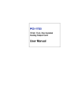
A.1 Overview
The PCI-1720 card uses eight variable resistors (VRs), two for each
channel, which allow you to calibrate each of the card’s four output
channels. The following information outlines the function of each
VR. Refer to the illustration shown below for the locations of the PCI1720’s VRs.
Figure A-1: PCI-1720 VR assignment
30
VR1
Channel 0’s full scale (gain) adjustment.
VR2
Channel 1’s full scale (gain) adjustment.
VR3
Channel 2’s full scale (gain) adjustment.
VR4
Channel 3’s full scale (gain) adjustment.
VR5
Channel 0’s offset adjustment.
VR6
Channel 1’s offset adjustment.
VR7
Channel 2’s offset adjustment.
VR8
Channel 3’s offset adjustment.
PCI-1720 User's Manual
You should use a precision voltmeter/ammeter to obtain accurate
readings when calibrating the PCI-1720. Standard procedures for
performing a calibration are given below.
A.2 Unipolar Output Calibration
1. Select an appropriate output range for the channel to be calibrated.
2. Set all digital input codes to 0. Then adjust VRn (n = 5, 6, 7, 8
depending on what channel is to be calibrated, see prior page) until
your voltmeter’s reading is 0.000 volts.
3. Set all digital input codes to 1 (see Unipolar Binary Code Table in
Section 4.3). Now, adjust VRn (n = 1, 2, 3, 4 depending on what
channel is to be calibrated, see prior page) until your voltmeter
shows a reading equal to the output voltage shown in the Unipolar
Binary Code Table in Section 4.3.
4. Repeat steps 2 and 3 until both of them are satisfied.
A.3 Bipolar Output Calibration
1. Select an appropriate output range for the channel to be calibrated.
2. Set all digital input codes to 100000000000. Adjust VRn (n = 5, 6,
7, 8 depending on what channel is to be calibrated, see prior page)
until your voltmeter’s reading is 0.000 volts.
3. Set all digital input codes to 1 (see Bipolar Binary Code Table in
Section 4.3). Now, adjust VRn (n = 1, 2, 3, 4 depending on what
channel is to be calibrated, see prior page) until your voltmeter
shows a reading equal to the output voltage shown in the Bipolar
Binary Code Table in Section 4.3.
4. Repeat steps 2 and 3 until both of them are satisfied.
Appendix A Calibration
31
A.4 Current Sink Calibration
1. Select the 0 ~ +5 V (unipolar) output range for the channel to be
calibrated.
2. Set all digital input codes to 0. Then adjust VRn (n = 5, 6, 7, 8
depending on what channel is to be calibrated, see prior page) until
your ammeter’s reading is 0.00 mA or 4.00 mA (Depending on
jumper setting JP1 to JP4, see Section 3.1.1).
3. Set all digital input codes to 1. Now, adjust VRn (n = 1, 2, 3, 4
depending on what channel is to be calibrated, see prior page) until
your ammeter shows a reading equal to 20.00 mA.
4. Repeat steps 2 and 3 until both of them are satisfied.
32
PCI-1720 User's Manual