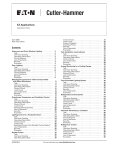
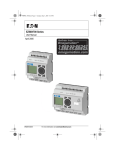
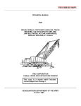
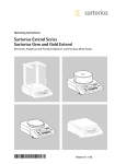
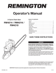
1
3010 Air Compressor Pump
Operation & Maintenance Manual
7.5 & 10 HP Electric
16 HP Gas
Duplex
7.5 & 10 HP Electric
Model #:
??????
Serial #:
82-36 Manual
1
PERFORMANCE SPECifications
Description
LXWXH
Phase
Voltage
Disp. CFM
SCFM
Pump Cyl. Pump RPM
7.5 HP Electric Horizontal 80 Gallon Tank
65" X 25" X 46"
1
230
32.6
24
4
600
7.5 HP Electric Horizontal 120 Gallon Tank
71" X 24" X 50"
1
230
32.6
24
4
600
7.5 HP Electric Vertical 80 Gallon
41" X 24” X 73”
1
230
32.6
24
4
600
7.5 HP Electric Horizontal 80 Gallon Tank
65" X 25" X 46"
3
208/230/460
32.6
24
4
600
7.5 HP Electric Horizontal 120 Gallon Tank
71" X 24" X 50"
3
208/230/460
32.6
24
4
600
7.5 HP Electric Vertical 80 Gallon
41" X 24" X 73"
3
208/230/460
32.6
24
4
600
10 HP Electric Horizontal 80 Gallon Tank
65" X 25" X 46"
3
208/230/460
43.5
32
4
800
10 HP Electric Horizontal 120 Gallon Tank
71" X 24" X 45"
3
208/230/460
43.5
32
4
800
10 HP Electric Vertical 80 Gallon
39.5" X 24" X 73"
3
208/230/460
43.5
32
4
800
10 HP Electric Vertical 120 Gallon
39.5" X 28" X 73"
3
208/230/460
43.5
32
4
800
(2) 7.5 HP Electric Horizontal 120 Gallon
81" X 26.5" X 52"
1
230
65.3
48
4
600
(2) 7.5 HP Electric Horizontal 120 Gallon
81" X 26.5" X 52"
3
208/230/460
65.3
48
4
600
(2) 10 HP Electric Horizontal 120 Gallon
81" X 26.5" X 52"
3
208/230/460
87.1
64
4
800
(2) 10 HP Electric Horizontal 200 Gallon
81" X 26.5" X 52"
3
208/230/460
87.1
64
4
800
16 HP Briggs & Stratton Gas Horizontal
30 Gallon Tank
50" X 23.5" X 43"
41
32
4
800
PUMP
Bore & Stroke
4 1/4" L, 2 1/8" H X 3 1/2"
7" x 8.25"
# Cyl.
Mounting Holes
Oil Capacity
Wt.
Max. Pressure
2
9 5/8" X 7 3/4"
1 3/4 qts.
214 lbs.
200 PSI
Permanent Adhesive, 2 colors with overlaminate
WARNING
CAREFULLY READ THE INSTRUCTION MANUAL INCLUDED WITH THE PRODUCT BEFORE OPERATION.
Air from this compressor will cause severe injury or death if used for breathing or food processing. Air used
for these processes must meet O.S.H.A. 29 c.f.r. 1910.134 or f.d.a. 178.3570 regulations.
RISK OF ELECTRICAL SHOCK - Has live electrical parts when power is connected. To reduce the risk of electric
shock, do not expose to rain, excessive humidity or running water. Store indoors. Must be grounded according to all
National, State and Local electrical codes to avoid electrical shock.
RISK OF INJURY - Has moving parts. Do not direct air stream at body. Use eye protection. May start or stop automatically
when power is connected. Should not be operated in places where there are children or pets.
RISK OF FIRE OR EXPLOSION “Must be installed and operated in well ventilated area that is free from
flammable gases, excessive humidity or running water”. Do not carry while painting. Use a minimum of 15
feet of hose when connecting the spray gun to the compressor. Do not spray combustible / flammable liquid in a
confined area. Do not smoke while spraying or spray where spark or flame is present. Keep compressor at least
20 feet away from spraying area.
RISK OF BURSTING - If the air tank becomes defective due to mechanical or chemical problems it must be
replaced. Never attempt to weld on or perform any other repair on the tank. Do not adjust regulator to result in
output pressure greater than marked maximum pressure of tool attached. The tank is a pressure vessel and should
be inspected on regular intervals by an accredited inspector.
Disconnect, tag and lock-out power source, then release all pressure from the compressor / tank before
attempting to install, service, relocate or perform any maintenance.
(O.S.H.A. Regulation 1910.147).
Do not use an extension cord with this compressor. Extension cords experience voltage drops and can result in
damage to the electric motor.
INSTALLATION
This compressor must be removed from wooden skid and permanently mounted to a
concrete floor. Recommend use of "Air Compressor Mounting Kit". See owner's
Contents
Page
Performance Specs................................................................................................................................................2
Safety Instructions..................................................................................................................................................4
Mounting Stationary Air Compressor.....................................................................................................................5
Wiring Recommendations......................................................................................................................................6
Wiring Diagram.......................................................................................................................................................7
Troubleshooting......................................................................................................................................................8
823010 Compressor Diagram..............................................................................................................................10
823010 Compressor Parts List.............................................................................................................................11
Cylinder Head Parts Diagram..............................................................................................................................12
Centrifugal Unloader/Electric Motor Maintenance................................................................................................13
Electric Unit Diagram and Parts List....................................................................................................................14
Gas Unit Diagram and Parts List.........................................................................................................................15
Unloader Adjustment............................................................................................................................................16
Duplex Unit Diagram and Parts List.....................................................................................................................17
Duplex Selective Switch Instructions...................................................................................................................18
Duplex Wiring Diagram Single Phase..................................................................................................................19
Duplex Wiring Diagram Three Phase...................................................................................................................20
Duplex Wiring Diagram Three Phase 460 Volts...................................................................................................21
Maintenance Schedule - Check Chart.................................................................................................................22
Maintenance Records..........................................................................................................................................23
Refrigerated Dryers, Pressure Washers, and Nitrogen Generators ...................................................................24
Battery Connections (Gas Engines).....................................................................................................................25
Warranty...............................................................................................................................................................26
Avoid electric shock- Unit must be dry before connecting to electricity and
during use.
Grounding and static conductivity - Ground unit as required by national
and local electrical codes. Added grounding, static-conductive belts and
other static-conductive controls may be needed in environments such as
grain elevators and chemical plants- ask a qualified engineer.
Duplex Unit is powered by two motors from two separate electrical
power sources. The motors start and stop automatically to maintain
tank pressure. Electric motors are programed to start with a delay. Avoid
injury: disconnect, tag, and lock-out both electrical power sources and
release air pressure from tank and air lines before attempting to install,
relocate or perform any maintenance or repair.
READ THE COMPLETE OWNER’S MANUAL AND ALL LABELS ON THIS
UNIT BEFORE INSTALLING OR USING.
SAFETY INSTRUCTIONS
When using air compressors and compressed air accessories, basic safety rules and precautions should always be
followed including the following:
1. Read all instructions fully before operating this
compressor.
2. Never use a compressor that is defective, operating abnormally, making strange noises, or otherwise appears defective. Stop using compressor immediately and arrange for repairs by an authorized service center.
3. Do not modify compressor. Always contact the autho-
rized service center for any repairs.
4. Use only the manufacturer’s replacement parts. Replacement parts not manufactured by Schrader Bridgeport may void your warranty and can lead to
compressor malfunction and personal injuries. Replacement parts are available from the manufac-
turer.
5. Wiring, starters, breakers and other related electrical equipment should conform to electrical codes when operating any electric air compressors. Electrical con-
nections should be made by a licensed electrician.
6. Always disconnect compressor from its power source and remove the compressed air from the tank before servicing, inspecting, cleaning, replacing, or checking any parts.
7. Do not operate compressor without belt guard. If main-
tenance or servicing requires the removal of a guard or safety feature, be sure to replace the guard or safety feature before resuming operation of the compressor.
8. Do not use gasoline compressor if Load Genie does not operate properly. Have defective Load Genie replaced by an authorized service center.
9. Avoid unintentional starting. Do not move the compres-
sor while connected to its power source or when the air tank is filled with compressed air.
10.Turn off the compressor when not in use. Then open the drain cock to discharge the compressed air from the air tank.
11. Do not expose compressor to rain. The compressor should be stored in a dry clean environment.
12. Do not use compressor in the presence of flammable liquids or gases. Compressor can produce sparks dur-
ing operation. Never use compressor in sites containing lacquer, paint, benzine, thinner, gasoline, gases, adhe-
sive agents and other materials, which are combustible or explosive.
13. Use only recommended air handling parts acceptable for minimum pressure. Never use pressurized air accessories or parts in the air system that are not suit-
able for the maximum air pressure involved. The risk of bursting exists with use of unsuitable equipment. Always maintain maximum pressure specified by the manufacturer.
4
14. If your compressor is used for spraying, do not spray in vicinity of open flame or other sources of ignition. Always direct paint or sprayed material away from compressor and locate compressor to minimize over spray accumulation on compressor or sprayer parts.
15. Do not wipe plastic parts with solvent. Solvents such as gasoline, thinner, benzine, carbon tetrachloride and alcohol may damage and crack plastic parts. Wipe plastic parts with a soft cloth, lightly dampened with soapy water and dry thoroughly. When using cleaning solvent, follow the instructions provided by the solvent manufacturer.
16. Keep pressure relief devices free from paint or other accumulation. The motor air vent must be kept clean so that air can freely flow at all times. Check for dust build-up frequently.
17. Do not install Shutoff valves in the discharge line between the compressor and the receiver unless a safety valve, with adequate flow capacity and pressure setting, is located between shutoff valve and the compressor. Never operate a compressor without all guards or safety features in place and in proper working order.
18. Proper maintenance and care is necessary to ensure safe operation of air compressor. Check compressor according to the maintenance schedule provided in this manual. Maintain compressor with care. Follow instructions for lubrication. Keep all screws, bolts, and plates tightly mounted. Check for damaged parts and air leaks, daily. Check for alignment of moving parts, binding of moving parts, guard, breakage of parts, and any other conditions that may affect the operation of compressor. Drain tank daily to prevent rust formation and damage.
19. Do not operate any compressor with damaged wir-
ing or hosing, or after the compressor or air handling parts have been dropped, damaged or show signs of deterioration, weakness or leakage. Do not use them if a deficiency is found. A unit that is damaged should be properly repaired or replaced by an authorized ser-
vice center unless otherwise indicated elsewhere in this Instruction Manual.
20. Keep clear of compressor while operating It may become extremely hot during operation. To reduce the risk of burns, do not touch tubes, heads, cyl-
inders or motors.
21. Never touch moving parts. Always wear safety gog-
gles or equivalent eye protection. Dress properly. Do not wear loose clothing or jewelry. These can be caught in moving parts. Wear protective hair covering to contain long hair.
22. Never aim compressed air at anyone or any part of the body.
23. Never operate a compressor in damp or wet location. Protect yourself against electric shock. Prevent body contact with grounded surfaces such as pipes, radia-
tors, ranges and refrigeration enclosures.
MOUNTING FOR STATIONARY AIR COMPRESSOR ONLY.
Disconnect power and release air pressure before
installing and/or performing maintenance.
UNPACKING INSTRUCTIONS
The two stage compressor was inspected at the factory and
packaged to protect against shipping damage. When you
unpack your unit, inspect for damaged or missing parts. If
there are any damaged or missing parts, the transportation
company’s agent should make a notation to the effect on
the Bill of Lading. Claims, should be settled directly with the
transportation company.
All Vertical Compressors are top heavy and can easily
tip over. Use appropriate lifting device for moving unit
to desired location. When using air compressors and
compressed air accessories, basic safety rules and
precautions should always be followed. Read the
compressor operating instruction before attempting to
assemble, install, operate, or maintain the product. Failure
to comply with the safety instructions could result in
personal injury and/or property damage.
The compressor must be placed in a clean and well
ventilated room. Compressor should be located at least
18-30 inches away from a wall or other obstruction that
will impede air flow through the fan-bladed flywheel. Do
not place compressor where heat is excessive. Provide
adequate fresh air and exhaust ventilation from area in
which the compressor is located.Place compressor on
a firm, level floor. Remove wood shipping skid before
installation. Failure to remove from wooden skid will void
all warranties. Permanent installations should be bolted to
the floor. Bolting holes are provided in the base feet. Shim
compressor level before bolting down to floor. Avoid putting
stress on your new compressor by using our Mounting Kit
(824678).
Stationary Air Compressor Mounting Kit
For Electric Models only. Order 824678.
Stationary Air Compressor Mounting Instructions
1. Select a location for mounting unit on a firm and
level floor.
2. Position unit and mark feet location in center hole of
each foot.
3. Prepare to drill holes by removing unit.
4. Drill each of the marked holes 3" in depth using a 3/4"
concrete drill bit. Blow out holes and insert lag shield
making sure they are flush with the floor.
5. Position unit over drilled holes.
6. Place one rubber isolation pad under each foot.
7. Assemble 1 1/2" metal/rubber washer and lag bolt into
each lag shield. Do not over tighten.
Flex Air Line Installation
Lag Screw
Bushing
Compressor Foot
Correct
Wrong
Rubber Pad
Lag Shield
1. Install 3/4" NPT nipple into tank outlet hole
2. Install 3/4" NPT Ball Valve.
3. Install 3/4" x 36" Flexible Hose.
Concrete Floor
Note: Teflon Tape should be used on all thread connections.
B
C
D
36" Flex Hose
A. Nipple
Warning: May bend & curve; do not kink.
A
Tank Drain
B. Outlet Hole
C. Ball Valve
D. Flex Hose
5
DIRECTION OF ROTATION
WIRING RECOMMENDATIONS
As the compressor starts, check the rotation of the units.
Standard rotation is clockwise, viewing the compressor from
the side of the sight glass. A rotation arrow is placed on
the flywheel at the factory. Should the rotation be incorrect,
disengage the power and correct the motor wiring.
Note: All wiring recommendations, performance, torque
readings are listed for each separate pump. All wire
sizes and breaker sizes are listed for each motor. Each
motor must be separate with it’s own breaker and wire
and have it’s own separate power source as listed in
charts.Installation or modifications should be made by a
Competent Electrician being sure that:
Warning: After the compressor is started, it will operate
automatically.
When the air pressure in the receiver reaches the preset
high pressure level the pressure switch opens, electrically
stopping the compressor drive motor. As the air is
used from the receiver the pressure drops allowing the
pressure switch to close at the preset low pressure level,
which restarts the driver motor. Meets ISO 100 viscosity
requirements (high viscosity SAE 30W to low viscosity
SAE40W). For ambient temperatures below 41˚F use oil
that meets ISO 68 viscosity requirements (high viscosity
SAE 20W). For ambient temperatures above 77˚F use oil
that meets ISO 150 viscosity requirements (high viscosity
SAE 40W).
LUBRICATION
Compressor may or may not be shipped with oil.
Change oil after first 50 hours (or two weeks) of operation.
Afterwards, change petroleum-based oils every 1000 hours
of operation.
Before operating, check the sight glass for oil level which
should be at halfway. Add oil to crankcase if level is below
halfway level. Do not over fill. This compressor requires a
non-detergent, 30 wt. oil such as Manufacturer # 826020.
Initial start up oil should be changed after first two weeks of
operation.
1. Magnetic starters with Thermal Overload are required for motor warranty and protection.
2. The power source is sufficient and service has adequate ampere rating. (See following chart).
3. The line wire is the proper size and that no other equip-
ment is operated from the same line. The following chart gives minimum recommended wire sizes for compressor installations. For longer lines, call manufacturer.
4. The Duplex air compressor must have two separate power sources, each motor must be wired independently of the other, using the chart below.
Various national and local codes and standards have been
set up covering electrical apparatus and wiring. These
should be consulted and local ordinances observed. Our
recommended wire sizes may be larger than the minimum
set up by local ordinances to prevent excessive line voltage
drop.
5. Failure to comply with all wiring instructions, including breaker sizes, wire sizes, and recommended wire length will void all warranties on electrical parts.
WARNING
Wire Size (Rubber Covered)
Do not overfill!
HP
Use a high quality, non-detergent petroleum-based
compressor oil containing anti-oxidant and corrosioninhibiting additives such as Manufacturer # 826020 to
lubricate the compressor pump.
Do not use detergent oils in the pump.
If oil turns milky replace oil and move unit to less humid
conditions.
For normal ambient termperatures between 41˚F and
77˚F use oil that meets ISO 100 viscosity requirements
(high viscosity SAE 30W to low viscosity SAE40W). For
ambient temperatures below 41˚F use oil that meets ISO
68 viscosity requirements (high viscosity SAE 20W). For
ambient temperatures above 77˚F use oil that meets ISO
150 viscosity requirements (high viscosity SAE 40W).
Ambient
Temp.
Viscosity
@
100ºF SSU
ISO
Viscosity
CS +
SAE No.
Wire Length
Single Phase
& DC
Three
Phase
208 V
230 V
230 V
460V
5
50' or less
8
8
10
14
7.5
50' or less
6
6
10
14
10
50' or less
8
14
15
50' or less
6
10
20
50' or less
4
10
25
50' or less
3
8
30
50' or less
2
8
Breaker Size
Single Phase
Three Phase
5
208 V
230 V
230 V
460V
5
60
60
30
15
7.5
80
80
45
20
10
60
25
80
40
0º - 40º
250-350
46-68
20
15
40º - 80º
450-550
100
30
20
120
60
80º - 120º
650-750
150
40
25
150
75
30
180
90
Under 0º Over 120º
6
Consult
Factory
Increase wire size up to next size
for each additional 50' feet.
WIRING DIAGRAM
1. Rewire motor per data plate on motor or instruction sheet.
2. Check pressure switch electric rating and replace if
necessary.
3. Check electric rating of thermal over load switch or
magnetic starter and replace complete switch or thermal
overload elements as required.
Incoming Power to be wired to Mag Starter only!
L1, L2, L3 indicates supply line terminals.
T1, T2, T3 indicates load terminals.
Pressure
Switch
MOTOR
single Phase
INCOMING POWER
L1
L2
L3
T1
T2
T3
JUMPER
LINE
MOTOR
three Phase
Pressure Switch
7
TROUBLESHOOTING
PROBLEM
1. Compressor will not operate.
POSSIBLE CAUSE
CORRECTIVE ACTION
1. No electrical power.
1. No electrical power.
2. Pressure switch not making
contact
2. See pressure switch adjustment.
1. Loose pulley, flywheel, belt,
belt guard
1. Tighten.
2. Lack of oil in crankcase.
2. Check for possible damage to
bearings, replenish oil.
3. Piston hitting the valve plate.
3. Remove the compressor cylinder
head and inspect for foreign
matter on top of the piston. Add
a new gasket and reassemble
the head.
4. Compressor floor mounting
loose.
4. Tighten.
5. Defective crankcase.
5. Repair or replace.
6. Excessive crankshaft end play.
6. Adjust and shim properly.
1. Main bearings.
1. Replace bearings.
2. Connecting rod bearing.
2. Tighten.
1. Connecting rod bearings.
1. Replace rod.
2. Wrist pins, wrist pin bearings.
2. Replace complete piston
assembly
1. Restricted air intake.
1. Clean or replace air filter.
2. Oil leaks.
2. Tighten bolts or replace gasket.
3. Worn piston rings.
3. Replace piston rings.
4. Wrong oil viscosity.
4. Drain oil, refill with oil or proper
viscosity. See Lubrication Section.
5. Compressor tilted too much.
5. Level compressor.
6. Scored cylinder
6. Replace cylinder.
2. Excessive noise in operation
3. Knock - same cycle as R.P.M.
4. Knock occurs while compressor
is loading.
5. Excessive oil consumption.
1. Compressor air intake restricted. 1. Clean air filter element and
check for other restrictions in the
intake system.
6. Oil in discharge air.
7. Compressor vibrates.
8
2. Worn piston rings.
2. Replace rings.
3. Excessive oil in compressor.
3. Drain down to full mark on sight
gauge.
4. Wrong oil viscosity.
4. Check viscosity. See Lubrication Section.
5. Piston rings installed up-side
down.
5. Install ring in proper position.
1. Mounting bolts loose.
1. Tighten.
2. Compressor not properly
mounted
2. Level compressor so that all feet
touch the floor before tightening
down.
3. Pulley and flywheel misaligned.
3. Realign.
4. Belts loose.
4. Tighten belts. See Maintenance
Section.
5. Bent crankshaft.
5. Replace crankshaft.
PROBLEM
POSSIBLE CAUSE
CORRECTIVE ACTION
8. Air blowing out of inlet
1. Broken first stage inlet valve.
1. Replace valve assembly.
1. Leaks or restriction.
1. Check for leaks or restriction or
piping. Repair.
2. Restricted air intake.
2. Clean or replace air filter element.
3. Slipping belts
3. Tighten belts. See maintenance
section.
4. Service hose too small.
4. Replace with larger hose
5. Excessive air requirement.
5. Limit air requirement to compressor
capacity.
1. Faulty check valve.
1. Bleed tank! Disassemble check
valve assembly, clean or Replace
faulty parts.
9. Insufficient pressure at point of
use.
10. Receiver does not hold
pressure when compressor
is unloaded
11. Excessive belt wear.
12. Excessive discharge air
temperature.
13. Receiver pressure builds
up slowly.
Danger
Do not disassemble the check valve with air in
tank. Note: check valve is always the first valve in
the line from the compressor to the
compressor.
1. Pulley out of alignment.
1. Realign motor pulley with
compressor flywheel.
2. Belts too tight.
2. Adjust tension.
3. Belts too loose.
3. Adjust tension. See maintenance
section.
4. Pulley or flywheel wobble.
4. Check for worn crankshaft, keyway
or pulley bore, resulting from
running with a loose pulley.
5. Nick in belt grove of pulley or
flywheel.
5. File smooth.
1. Dirty cooling surfaces.
1. Clean cooling surfaces of cylinder,
intercooler and discharge tube.
2. Poor ventilation.
2. Improve ventilation or relocate
compressor. See install instructions.
3. Blown head gasket.
3. Replace head gasket.
4. Restricted air intake
4. Clean or replace air filter element.
5. Worn valves.
5. Repair or replace valves.
1. Dirty air filter.
1. Clean or replace filter element.
2. Blown cylinder head gasket.
2. Install new gasket.
3. Worn or broken low pressure
intake or discharge valves.
3. Install new head gasket.
4. Air leaks.
4. Tighten joints.
5. Loose belts.
5. Tighten belts. See maintenance
section.
6. Speed too slow.
6. Check speed.
9
823010 COMPRESSOR PUMP
823010 Compressor Pump
6
13
59
69
61
62
55
68
15
48
21
51
57
72
65 13
L.P.
INTAKE
VALVE
L.P.
INTAKE
VALVE
L.P.
EXHAUST
VALVE
H.P.
INTAKE
VALVE
16
H.P.
EXHAUST
VALVE
24
52
19
46
67
37
58
47
41
25
50
56
13
43
53
60
66
44
34
40
23
32
54
3
22
45
35
1
5
6
13
45
75
71
64
74
9
49
29
35
36
81
31
10
80
79
78
75
77
17
12
8
16
6
13
6
41
25
NA210
44
NA210EX 3010 111607.ai DD
Recommended Torque Readings
Head Bolts
Valve Retainer
Rod Bolts
Crankcase Bolts
Side Cover Bolts
Front and Rear Cover Bolts
Manifold Bolts
Flywheel Bolts
Intercooler Bolts
10
11
7
13
30
76
12
4
2
16
17
33
39
6
42
27
16
38
14
14
63
43
28
70
18
13
66
26
20
Foot
pounds
50-55
80-90
30
30-40
30-40
30-40
30-40
65-70
30-40
823010 TWO-STAGE 4 PISTON COMPRESSOR PUMP
Item
Part
Description
QTY
Item
Part
Description
QTY
1
82708001
Crankcase
1
43
82706001
Elbow Aftercooler
2
2
82709001
Crankshaft
1
44
82703015
Elbow Copper
2
3
82050158
Bearing Front
1
45
82727136
Elbow Intercooler
2
4
82701000
Cap Front Bearing
1
46
82720002
Piston - HP
2
5
82070163
Gasket Front Cap
1
47
82050122
Insert Rod - Bearing
4
6
*G.H
Cap screw Hex M8X20
18
48
82727001
Valve Assembly - HP Inlet
2
7
82060068
Seal - Shaft
1
49
82090095
Shim .015 Brg Adjustment
1
8
82050159
Bearing Rear
1
49
82090094
Shim .010 Brg Adjustment
1
9
82070172
Gasket Rear Cap
1
49
82090093
Shim .005 Brg Adjustment
1
10
82728004
Centrifugal Unloader Adapter Plate
1
50
82100101
Dowel Alignment
8
11
82713000
Flywheel 19”
1
51
82719088
Set HP Piston Rings
2
12
See 3 & 8
Bearing - Cap
2
52
82729006
Wristpin HP Piston
2
13
82070201
Gasket Copper
24
53
*G.H
Lockwasher 10
8
14
82705107
Rod Connecting Steel w/ Needle Bearing
4
54
82070203
Gasket Copper
12
15
82727000
Valve Assembly - LP Inlet
4
55
82727003
Spacer Inlet Valve
6
16
*G.H
Pipe plug
7
56
82951
Valve Safety 200 PSI ASME
1
17
82020147
Cover Crankcase Side
2
57
82727002
Valve Assy HP/LP Discharge
4
18
82200100
Snap ring - Internal
8
58
*G.H.
Capscrew SKT Head M8X25
8
19
82729000
Wrist pin - LP Piston
2
59
82727136
Cover Valve
6
20
82720000
Piston LP 105mm
2
60
*G.H
Capscrew SKT Head M10X45
8
21
82719064
Piston Ring Set LP
2
61
82727134
Retainer Inlet Valve
6
22
82070162
Gasket Cylinder To Crankcase
2
62
82727135
Retainer Discharge Valve
4
23
*G.H.
Cap screw Hex M10X25
12
63
*G.H
Lockwasher 8
8
24
*G.H.
Cap screw Hex M12X70
16
64
82718017
T-Fitting Copper
2
25
82728002
Holder Unloader
1
65
*G.H.
Capscrew Hex M8X85
8
26
*G.H.
Cap screw Hex M16X80
1
66
82070167
Gasket Aftercooler
4
27
82070161
Gasket Cylinder Head
2
67
82070169
Gasket Intercooler
4
28
82710000
Head Cylinder
1
68
82727004
Spacer Discharge Valve
4
29
82703011
Breather
1
69
82070170
Gasket Valve Cover
6
30
*G.H
Oil Drain Plug 3/8” NPT
1
70
*G.H
Lockwasher 16
1
31
*G.H.
Cap screw Skt HD M6X20
4
71
82703013
Breather Tube
2
32
82711000
Cylinder
1
72
82070202
Copper Valve Seat Gasket
10
33
8232574
Filter Inlet Assembly
2
73
826155-S
Elbow Valve & Unloader
1
34
822580
Filter Inlet Element
2
74
82701029
Cap Rear
1
35
82070165
Gasket Side Cover
2
75
82100100
Pin - Hinge
2
36
82288700
Oil Level Sight Glass (Copper)
1
76
82728000
Weight Unloader
1
37
82706000
Intercooler
1
77
82723003
Spring Unloader
1
38
*G.H.
Nut Hex - M16
1
78
82728003
Plunge Unloader
1
39
82080029
Key Flywheel
1
79
82070166
Gasket Unloader Cover
1
40
82706003
Aftercooler
1
80
82120058
Nut Adjustment Lock
1
41
82947
Valve Safety 60 PSI ASME
2
81
82160002
Bushing Reducing
2
42
82705003
Dipper Oil
4
n/a
82720123
Complete Plunger Assembly (for unloader)
1
*Notes:
*G.H. General Hardware
820185 - Gasket set inclues: complete set of gaskets for pump.
820707 - Overhaul kit includes: Gasket set, ring set and valve assemblies for pump and two air filters
820182 - Valve & Head Overhaul Kit includes gaskets for pump head, two air filters and valve assemblies.
11
CYLINDER HEAD
Order # 82288787 Spanner Tool,
to remove Valves.
Air Compressor Cylinder Head
Parts Breakdown
Valve Components
Torque: Foot Lbs.
Headbolts: 55
Valve Retainer: 80
6
13 - Copper Washer
59 - Cap
L. P & H.P
Exhaust
69 - Gasket
L. P Intake
H.P Exhaust
62 - Valve Retainer
61 - Valve Retainer
55 - Retainer Spacer
68 - Retainer Spacer
15 - Valve
48 - Valve
57 - Valve
72 - Valve Seat
L. P
Intake
Valve
Air Filter Intake
12
L. P
Intake
Valve
L. P
Exhaust
Valve
H.P
Exhaust
Valve
H.P
Intake
Valve
CENTRIFUGAL UNLOADER
Ill. # Description
Part No.
10
Cap - Rear
82701029
97
Holder - Unloader
82728002
98
Weight - Unloader
82728000
100
Pin - Hinge
82100100
103
Spring - Unloader
82723003
107
Plunger - Unloader
82728003
96
Cover - Centrifugal
Unloader
82728004
105
Gasket - Unloader Cover
82070166
102
Capscrew - Skt Hd
M6x20
99
Elbow - Valve & Unloader
10
100
103
102
98
97
107
99
71
06
G.H.
105
826155-S
98
96
MAINTENANCE & TROUBLE SHOOTING
FOR ELECTRIC MOTOR
Warning: Disconnect power before servicing
Electric Motor.
General Inspection
Inspect the motor at regular intervals, approximately every
500 hours of operation or every 3 months, whichever
occurs first. Keep the motor clean and the ventilation
openings clear. The following steps should be performed at
each inspection:
1. Check that the motor is clean. Check that the interior and exterior of the motor is free of dirt, oil, grease, water, etc. Oily vapor, paper pulp, textile lint, etc. can accumulate and block motor ventilation. If the motor is not properly ventilated, overheating can occur and cause motor failure.
2. Use a "Megger" periodically to insure that the integrity of the winding insulation has been maintained. Record the Megger readings. Immediately investigate any signifi
cant drop in insulation resistance.
3. Check all electrical connectors to be sure that they are tight.
Lubrication & Bearings
Bearing Grease will lose its lubricating ability over time,
not suddenly. The lubricating ability of grease (over time)
depends primarily on the type of grease, the size of the
bearing, the speed at which the bearing operates and the
severity of the operating conditions. Good results can be
obtained if the following recommendations are used in your
maintenance program.
Type of Grease:
A high grade ball or roller bearing grease should be used.
Recommended grease for standard service conditions is
Polyrex EM (Exxon Mobile). Equivalent and compatible
greases include: Texaco Polystar, Rykon Premium #2,
Pennzoil Pen 2 Lube, and Chevron SRI.
Lubrication Intervals:
Recommended lubrication intervals are approximately every
9500 hours.
Lubrication Procedure:
Be sure that the grease you are adding to the motor is
compatible with the grease already in the motor. Consult
your Baldor distributor or an authorized service center if a
grease other than the recommended type is used.
With Grease Outlet Plug.
1. Clean all grease fittings.
2. Remove grease outlet plug.
3. If the motor is stopped, add the recommended amount of
grease. If motor is to be greased while running, a slightly
greater quantity of grease will have to be added. Add
grease slowly until new grease appears at shaft hole in
the endplate or purge outlet plug.
4. Re-install grease outlet plug.
Without Grease Outlet Plug.
1. Disassemble motor.
2. Add recommended amount of grease to bearing and
bearing cavity. (Bearing should be about 1/3 full of grease
and outboard bearing cavity should be about 1/2 full of
grease). Note: bearing is 1/3 full when only one side of
bearing is completely full of grease).
3. Assemble motor.
Lubrication Amounts
Weight of Grease
to be added:
0.61 Ounces
17 Grams
Volume of
Grease to be
added:
1.2 Cubic in.
3.9 Teaspoon
13
ELECTRIC AIR COMPRESSOR
ILL. #
Single Phase
Horizontal
Description
1
Pump
2
Electric Motor 7.5 HP
2
Electric Motor 10 HP
3
Magnetic Starter 230 Volt
3
Magnetic Starter 460 Volt
Single Phase
Vertical
Three Phase
Vertical
3010
3010
3010
3010
827500MA
827500MB
827500MA
827500MB
8215PW
823710PW
8215PW
823710PW
821000MB
821000MB
823710PW460
4
Tank 80 Gallon
8282
8282
4
Tank 120 Gallon
8283
8283
5
Motor Pulley 7.5 HP
823806
82306
5
Motor Pulley 10 HP
6
Check Valve
7
Belt Guard & Belt Guard Pan
8
823710PW460
8281
8281
82288673
82306
82306
823764
823764
82C7510
82C7510
82P7510
82P7510
82660
82660
82660
82660
Belt Guard Brace
82661
82661
82661
82661
Belts 7.5 HP
82890
82890
82890
82890
8
Belts 10 HP
82826
82826
82826
82826
9
Tank Drain
82650
82650
82650
82650
10
Pressure Gauge
82513
82513
82516
82516
11
Pressure Switch 140/175
82775
82775
82775
82775
12
Bleeder Tube
82600
82600
82600
82600
13
Discharge Tube
82603 &
AC Model#
82603 &
AC Model #
82603H &
AC Model #
82603H &
AC Model #
14
3/4" Brass Adaptor
82623
82623
82623
82623
15
Safety Valve 200 PSI
82951
82951
82951
82951
16
3/4 Street Elbow
17
Air Filter Assembly 1" Intake
1
17
13
Three Phase
Horizontal
82654
82654
82654
82654
8232574
8232574
8232574
8232574
14 16
17
7
8
2
5
6
11
15
10
12
3
4
14
9
Gas Air Compressor
ILL.#
Description
Part Number
1
Pump
823010
2
Briggs Gas Engine
82847V
3
Engine Pulley
823804
4
Tank
5
Check Valve unloader
6
Belt Guard & Belt Guard Pan
7
Belts
82827
8
Tank Drain
82650
9
Pressure Gauge
82516
10
Bleeder Tube
82600
8279
82709
82660R
11
Discharge Tube
12
3/4" Brass Adaptor
82603H & Model Number
82623
13
Safety Valve 200 PSI
82951
14
3/4" Street Elbow
82654
15
1/2" X 3/4" Brass Elbow
82595
16
Throttle Cable
17
1/4" Tee
82652
18
1/2" Street Elbow
82672
19
Air Filter Assembly 1" NPT Intake
20
Belt Guard Bracket
82661
Replacement Air Filter Element
822580
82205BNK
8232574
Pulley and Bushing
3
7
20
10
6
1
19
2
Discharge Tube
3/4
14
12
7
11
11
3
15
5
5
TNEV
4
1/2
13
16
9
8
Pressure Gauge and Safety Valve
9
17
13
15
UNLOADER ADJUSTMENT
Installation
Load Genie 82709
Inlet (Connected to Compressor)
The Load Genie has 1/2 NPT “IN” and “OUT” ports
and is suitable for compressors with a discharge
of up to 32 SCFM . The Load Genie is typically
installed onto the tank with a short pipe nipple. The
“OUT” port must be connected directly to the tank
with no other check valves in between the tank and
the Load Genie.
Note:
On some retrofit applications, there may have been
a type of check valve known as an “In Tank” check
valve previously installed. Make sure there is a
clear air path between the tanks and “OUT” port
before installing the Load Genie. The compressor
discharge line can now be routed into the “IN” port
of the Load Genie.
Easy Start Lever
Range Adjustment Screw
Range Jam Nut
Differential Adjustment Screw
Differential Jam Nut
1/8 NPT
Throttle Control Port
VENT
Vent Port
(See rear, open to
Atmosphere)
The installation is now complete.
Regulator Adjustment
Cutout pressure is adjustable from 60 PSI to 175
PSI with the standard silver spring. The differential
Out (Connected to Tank)
(difference between cut-out and cut-in pressures)
is typically set at the factory at approximately 15%
of the cut-out pressure. This is usually a suitable differential
and will not normally need to be readjusted.
Loadgenie3 112807.ai
Starting Unit
1. Loosen range screw jam nut first.
2. Turn range screw clockwise to raise cut-out and cut-in
pressure levels and counter clockwise to decrease
cut-out and cut-in levels.
3. Start compressor and note cut-out and cut-in pressures.
Make adjustments as necessary using range adjustment
screw, when acceptable, tighten range adjustment
screw jam nut.
4. Adjust the cut-in pressure to the desired level per steps
#1, #2, and #3, as shown.
5. Loosen differential screw jam nut and turn differential
screw clockwise to raise cut-out pressure and counter
clockwise to decrease the cut-out pressure. Tighten
differential screw jam nut when desired cut-out pressure
is set. Since step 5 should not change the desired cut-in
pressure set in step # 4, adjustment is now complete.
Use with Gasoline Engine Throttle
Controls
A 1/8 NPT tapped port in the end of the Load Genie allows
the use of a throttle control to slow down the driving engine
when in the cutout (venting) mode. The throttle control is
simply a small (e.g., 1/2” dia. X 1” stroke) single-acting,
spring return air cylinder which moves the throttle lever
on the engine to the idle position when the cylinder is
pressurized while in the cut-out mode.
Throttle control is specifically designed for this application. It
is important that the throttle control air cylinder is leak-tight
and that all connections between that Load Genie and the
air cylinder are leak-tight.
16
Easy Start: Place Easy Start Lever in upright position, Start
Unit, when running smoothly flip lever to run position.
Start Position
Run Position
DUPLEX ELECTRIC AIR COMPRESSOR
ILL.#
Description
1
Pump
2
Electric Motor 7.5 HP
2
Electric Motor 10 HP
3
Controller
82289051
82289048
4
Tank 120 Gallon
4
Tank 200 Gallon
5
Motor Pulley 7.5 HP
5
Motor Pulley 10 HP
6
Check Valve
7
Single Phase
Three Phase
460 Three Phase
823010
823010
823010
827500MA
827500MB
827500MB
821000MB
821000MB
82289710
82289050
82289048
82289048
82289049
82289049
823806
823806
823764
823764
82P7510
82P7510
82P7510
Belt Guard & Belt Guard Pan
82660R
82660R
82660R
8
Belt Guard & Belt Guard Pan
`82660
82660
82660
9
Belts 7.5 HP
82890
82890
82890
9
Belts 10 HP
82826
82826
10
Tank Drain
82650
82650
82650
11
Pressure Gauge
82516
82516
82516
12
Pressure Switch 140 / 175
82775
82775
82775
13
Pressure Switch 130 / 165
(need to adjust)
82775
82775
82775
14
Bleeder Tube
82600
82600
82600
15
Discharge Tube Left
82603H & Model
Number + left
82603H & Model
Number + left
82603H & Model
Number + left
15
Discharge Tube Right
82603H & Model
Number + right
82603H & Model
Number + right
82603H & Model
Number + right
823806
16
Safety Valve 200 PSI
17
Air Filter Assembly 1" NPT Intake
1
82951
82951
8232574
8232574
14 15
17
17
82951
8232574
89 2
2
5
7
17
14 15
1
17
5
3
6
6
11
4
12
16
13 10
17
DUPLEX UNITS ONLY
WARNING
Selective Selective Switch Instructions.
Duplex Unit is powered by two motors from two
separate electrical power sources. The motors start
and stop automatically to maintain tank pressure.
Electric motors are programed to start with a delay.
Avoid injury: disconnect, tag, and lock-out both
electrical power sources and release air pressure
from tank and air lines before attempting to install,
relocate or perform any maintenance or repair.
The Duplex control panel controls the operation of two
compressor motors by sharing the load between the two
motors. The panel contains 2 contactors with re-settable
motor-overload protective devices, and a Siemens LOGO™
logic device. Motor-A & Motor-B are supplied separate input
power sources. The power is connected to each of the
contactors. The LOGO device and the control circuits take
power from the Motor-A source.
Operation
Troubleshooting
When power is applied to the Motor-A and/or Motor-B
contactors, the panel is “hot”. That is, the pressure switch
wires and motor output leads may be “hot”.
1. Check that Motor inputs terminals are wired securely and are powered.
2. Check the motor connections are complete and secure.
3. Check pressure switch connections.
4. Check two control power fuses mounted in terminal blocks.
5. Check motor overloads – may need resetting.
6. Check LOGO controller light : OFF=no power, RED = powered but faulted, GREEN= powered and running OK.
Selector-Switch in LEFT position (Motor-A)
Motor-A operates when the 175-psi switch is made. The
135-psi switch is not used. Motor-B doesn’t operate.
Selector-Switch in RIGHT position (Motor-B)
Motor-B operates when the 175-psi switch is made. The
135-psi sensor is not used. Motor-A doesn’t operate.
Selector-Switch in CENTER position (Auto)
This position is for automatic operation. One motor
operates with a 15 second delay when the 175-psi switch
is made while the 135-psi switch does not. If the 175-psi
switch is made for more than 5 minutes, the second motor is
started. If both the 175-psi and 135-psi switches are made,
then both motors start with a 15 second delay between
starting of motors. Once air pressure is satisfied and both
motors stop, the motor that didn’t run last will start next.
That is, when the 175-psi switch is made, the motor which
had started second the last time is started first the next time.
See wiring diagram.
AUTO
Air
Compressor
A
18
Air
Compressor
B
DUPLEX UNITS ONLY Wiring Diagram for 82289051
Single Phase 208/230 Volt Controller / Magnetic Starters
240 VOLT 1 PHASE
LINE IN
FROM DISCONNECT A
LINE IN
FROM DISCONNECT B
BLACK
RED
L1
L2
L3
L1
L2
STARTER
L3
X
X
RESET
T1 T2 T3
PRESSURE SW B
STARTER
.5 A
PRESSURE SW A
COMP
B
FUSE 2
.5 A
COMP A BOTH COMP B
COMP
A
FUSE 1
RESET
T1 T2 T3
L1
L2
I1
I2
I4
I5
EZ512-AC-RCX
L1
MOTOR A
Q1
L1
Q2
MOTOR B
A1
A1
COMP A
COIL
COMP B
COIL
A2
O.L.
A2
O.L.
19
DUPLEX UNITS ONLY Wiring Diagram for 82289049
Three Phase 208/230 Volt Controller / Magnetic Starters
THREE PHASE 240 VOLT
LINE IN
FROM DISCONNECT A
LINE IN
FROM DISCONNECT B
BLACK
RED
FUSE 1
.5 A
L1
L2
L3
L1
L2
STARTER
X
X
RESET
T1 T2 T3
RESET
T1 T2 T3
L1
L2
I1
I2
I4
EZ512-AC-RCX
L1
MOTOR A
Q1
L1
Q2
MOTOR B
A1
A1
COMP A
COIL
COMP B
COIL
A2
20
PRESSURE SW B
STARTER
L3
PRESSURE SW A
COMP
B
.5 A
COMP A BOTH COMP B
COMP
A
FUSE 2
O.L.
A2
O.L.
I5
DUPLEX UNITS ONLY Wiring Diagram for 82289050
Three Phase 480 Volt Controller / Magnetic Starters
THREE PHASE 480 VOLT
LINE IN
FROM DISCONNECT A
LINE IN
FROM DISCONNECT B
BLACK
FUSE H1 .25 A
RED
H1
H2 H3
X1-X3
FUSE X1 .5 A
L1
L2
L3
L1
L2
STARTER
L3
X
X
RESET
T1 T2 T3
PRESSURE SW B
STARTER
FUSE X2 .5 A
PRESSURE SW A
COMP
B
X2-X4
COMP A BOTH COMP B
COMP
A
FUSE H2 .25 A
H4
RESET
T1 T2 T3
L1
L2
I1
I2
I4
I5
EZ512-AC-RCX
L1
MOTOR A
Q1
L1
Q2
MOTOR B
A1
A1
COMP A
COIL
COMP B
COIL
A2
O.L.
A2
O.L.
21
MAINTENANCE SCHEDULE - CHECK CHART
PROCEDURE
Daily
Check Oil Level. Caution! Do not overfill.
X
Give Compressor overall visual check.
X
Drain moisture accumulation from the air receiver and system
piping.
X
Weekly
Check the air distribution system for air leaks. Remove and
clean intake air filters. Do not oil.
X
Clean cooling surfaces of compressor, intercooler and
aftercooler
X
Check V-belts for tightness. Belt tension should be adjusted
to allow approximately 1/4 - 1/2 inch deflection with normal
thumb pressure.
X
Turn power off and clean dust and foreign material from
cylinder head, motor, fan blade, air lines, intercooler and tank.
X
Monthly
Operate safety valves (pressure relief valve).
X
Replace or clean intake filter element monthly or more often
if needed.
X
Inspect oil for contamination and change if necessary.
X
Check belts for correct tension and alignment.
X
Check flywheel and motor pulley for tightness. Check
pulley clamp bolts and set screws for tightness.
X
Quarterly
Every 90 days also check entire system for air leakage
around fittings, etc. using a soap solution. Tighten nuts and
cap screws as required.
X
Every 90 days or 1,000 operating hours, whichever comes
first, change crankcase oil. Use type and grade recommended
in paragraph on lubrication. Change oil more frequently if
compressor is located in dirty environment.*
X
Inspect valve assemblies.
Yearly
XX
Inspect cushion chamber, if so equipped, and discharge line
for excessive carbon accumulations.
X
Inspect pressure switch diaphragm and contact points.
X
Inspect contact points in motor starter.
X
Service electric motor.
‡
‡
‡
‡
Service gasoline engine.
‡
‡
‡
‡
X - Check more often if extremely dirty conditions exists.
XX - Every 6 months.
‡ Per Manufacturer’s Recommendations.
* Change oil after first 50 hours (or two weeks) of operation if new or relocated.
22
Notes & Maintenance Record
Date
Oil Change
Air Filter
Change
Belt
Check
Change
Comments
23
We are proud to offer you additional
products to support your business needs.
Refrigerated Dryers, Pressure Washers,
and Nitrogen Generators
Direct Flow - Variable Flow - High Inlet
Temperature
To ensure maximum performance of your system we
can match your Air Compressor with a Refrigerated
Dryer. A Refrigerated Air Dryer will pay for itself by
extending the life of your tools and equipment by
eliminating water vapor from the air line. Dryer
installation is important to all shop air systems but
absolutely critical for paint and body shops where a
quality paint finish is a must.
Gas - Electric - Cold Water - Hot Water
Consumer to Industrial Pressure Washers
We sell a full Line of Pressure Washers and
Accessories ranging from Light Duty to large
Commercial and Industrial Pressure Washers.
Nitrogen Generators, Purge & Inflations
Systems
Stationary and Mobile options available. Meeting the
demands of the ever-growing Tire Industry, we now
offer Nitrogen Generators, Purge and Refill Systems.
Nitrogen filled tires have been used in the Racing and
Air craft for years. Commercial and Consumer use is
on the rise. The benefits and sales opportunities of
Nitrogen filled tires far outweigh the minimal setup and
cost associated with this technology.
Please call our technical support team
who will be happy to direct you to a sales
representative for any of the product lines
listed above and/or for questions regarding additional air compressor needs.
1-800-288-1804 ext. 620
24
Battery Connections for Electric Starter (on gas engines)
Use a 12-volt battery with an ampere-hour rating of at least 300 CCA.
Be careful not to connect the battery in reverse polarity, as this will short circuit the battery charging system.
Always connect the positive (+) battery cable to the battery terminal before connecting the negative (-) battery
cable, so your tools cannot cause a short circuit if they touch a grounded part while tightening the positive (+)
battery cable end.
Warning!
Warning!
A battery can explode if you do not follow the correct procedure, seriously injuring anyone nearby.
Drain all air from the tank before starting. Starting
the engine with air in the tank will overload the
starter and may lead to starter failure.
Keep all sparks, open flames, and smoking materials away from the battery.
WARNING: Battery posts, terminals and related accessories contain lead and lead compounds.
Wash hands after handling.
1.Connect the battery’s positive (+) cable to the
starter solenoid.
2. Connect other end to a 100 amp. circuit breaker
(accessory side).
3. Connect another cable to the circuit breaker
(battery side).
4. Connect cable to the battery’s positive (+) side.
5. Connect the negative (-) cable to the engine
mount bolt.
6. Connect the negative (-) cable to the battery.
•
•
•
Battery cables should be #6 or #8 (braided cables
with factory crimped ends).
Cables should not exceed 25 feet total.
Positive = 25 ft. Negative = 25 ft.
Circuit breaker is to protect the unit and the vehicle
against positive grounding.
25
Schrader International Inc.
Warranty Statement
For (1) one year from the date of purchase, Schrader
International Inc. will replace or repair for the original
purchaser free of charge, any part or parts found upon
examination by manufacturer/any Authorized Service
Center to be defective in material or workmanship or
both. This warranty shall not be effective unless the
warranty registration certificate is completely filled out
and returned to Schrader International Inc. within thirty
(30) days from the delivery of the equipment to the
original end-user.
All transportation charges for parts submitted for
replacement under this warranty must be borne by the
purchaser. There is no other express warranty. Implied
warranties, including those of merchantability and
fitness for a particular purpose are limited to one year
from the date of purchase and to the extent permitted
by law, any and all implied warranties are excluded.
This is the exclusive remedy, and liability for consequential damages under any and all warranties are
excluded to the extent exclusion is permitted by law.
All claims pertaining to the merchandise in this schedule must be filed with Schrader International Inc. within
12 months of the invoice date, and a registration card
is on file with Schrader, or they will not be honored.
Prices, discount, and terms are subject to change
without notice or as stipulated in specific product quotations. All agreements are contingent upon strikes,
accidents, and other causes beyond our control. All
shipments are carefully inspected and counted before
leaving the factory. Please inspect carefully any
receipt of merchandise, noting any discrepancy or
damage on the carrier’s freight bill at time of delivery.
Discrepancies or damage, including hidden or obvious
that occurred in transit are the carrier’s responsibility
and related claims should be made by the customer
directly with the carrier.
26
To locate the closest Authorized Service Center for
service assistance, resolution of a service problem or
for product information and operation, call or write to:
Schrader International Inc.
205 Frazier Road
Altavista, VA 24517
Email: [email protected]
1.800.288.1804
Tech Service, ext. 304, 868, 513
What is not covered under this warranty:
• Electric motors or gasoline engines are
covered by the Original Manufacturer’s
Warranty and should be returned (by the
customer) to their authorized service
center for service.
• Consumer compressors used in
commercial, industrial or rental purposes
will be covered by warranty for (90) ninety
days from date of purchase only.
• Any failure that results from an accident,
purchaser’s abuse, neglect or failure to
operate products in accordance with
instructions provided in the owner’s
manual(s) supplied with compressor.
• Pump or valve failure caused by rain,
excessive humidity, corrosive environments
or other contaminants.
• Cosmetic defects that do not interfere with
the compressor’s functionality.
• Damage due to incorrect voltage or
improper wiring.
• Pump wear or valve damage caused by any
oil contamination or by failure to follow
proper oil maintenance guidelines.
• This warranty is invalid if the factory-applied
serial number has been altered or removed
from the product, or an electric compressor
has been used in conjunction with a
generator.
• Freight damage
CUSTOMER SERVICE • PARTS
1-800-828-0355
TECHNICAL SERVICE • PARTS
1-800-288-1804
Schrader International Inc.
P.O. Box 668 • 205 Frazier Road
Altavista, Virginia 24517
3010manual051509