1
Scanner Maintenance and Calibration
8
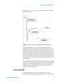
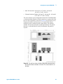
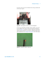
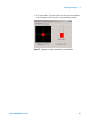
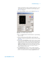
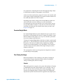
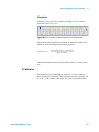
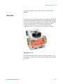
on the edge of a feature while the scan was moving upwards. The red
marker was placed on the same feature during the downward scan.
Figure 103 Markers indicating trace and re-trace Y hysteresis
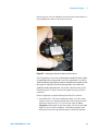
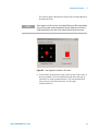
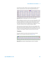
While scanning in one direction, focus on one step of the grating. As the
scan data is plotted position a marker on this edge. Wait for the scan in
the opposite direction to occur and position a second marker on the
same edge after the plot has been updated. In the example below, about
2 microns of hysteresis can be measured using this method.
After increasing or decreasing the Y Hysteresis term, alignment of the
individual edges should be confirmed across the full range of the Y axis.
It may be necessary to update the hysteresis term more than once before
all edges become aligned in both the upward and downward scans.
Y Sensitivity
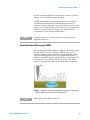
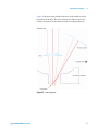
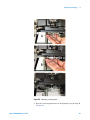
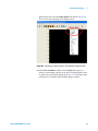
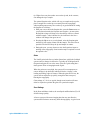
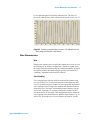
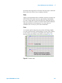
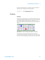
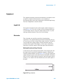
Using the Vertical Cross-section tool, measure the top-to-bottom
distance of a set of features across the scan (Figure 104).
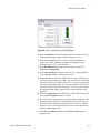
Figure 104 Cross-section of several features to check Y sensitivity
Agilent 5500 SPM User’s Guide
150


















































































![Instalar y actualizar NetBSD-current [e] - Redes](http://vs1.manualzilla.com/store/data/006226705_1-100e74543fa3bea9f822ce307be8d1b9-150x150.png)