1
11
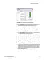
MAC III Mode
10 V, beyond which the signal will be clipped. The
default value is x1 (the amplitude times 1).
Drive Mechanism
The mechanism (AAC, MAC or Top MAC).
Zero Phase
Sets the phase at the current frequency to zero,
making it easier to interpret phase changes from
the current value.
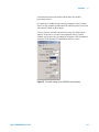
Q Control On
By applying a phase-shifted version of the
cantilever drive signal on top of the drive signal, Q
control can either increase or decrease the effective
quality factor of the system. Select this box to
enable the Q Control feedback loop. By default, Q
Control is turned Off.
Drive (%)
Sets the amplitude of the Q Control phase-shifted
signal, stated as a percentage (0-100 %) of the
maximum available.
Optimize
Sets the optimal Q-Control Phase Shift and Drive.
On the Output tab, the Pass Through boxes for Deflection and Friction
are selected, passing these values from the microscope through to the
AFM controller.
Amplitude 1 and Phase 1 are routed to the Aux 1 and Aux 2 outputs,
respectively, to be used as inputs to image buffers. These signals can be
viewed by selecting Aux 1 or Aux 2 from the drop-down list in the
Realtime Images window.
EFM
In EFM Mode, Lock-in 1 is used to drive the cantilever, with the
Deflection channel as its Input. Lock-in 2 provides an AC tip bias, also
with the Deflection channel as its Input. The actual Deflection input
during scanning is the oscillation amplitude.
NOTE
For EFM mode, the Bias switch on the back of the Head Electronics Box
must be set to Tip.
Agilent 5500 SPM User’s Guide
177
















































































![Instalar y actualizar NetBSD-current [e] - Redes](http://vs1.manualzilla.com/store/data/006226705_1-100e74543fa3bea9f822ce307be8d1b9-150x150.png)