1
Chapter 3
Connectors
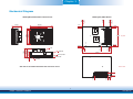
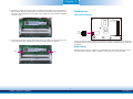
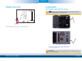
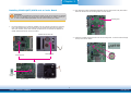
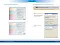
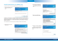
5. Grasping the module by its edges, align the module into the socket at an approximately 30
degrees angle. Apply firm even pressure to each end of the module until it slips down into
the socket. The contact fingers on the edge of the module will almost completely disappear
inside the socket.
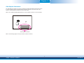
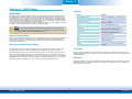
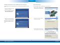
CPU Fan Connector
Sense
+12V
Ground
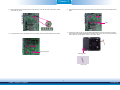
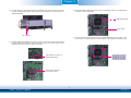
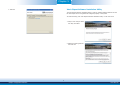
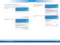
6. Push down the module until the clips at each end of the socket lock into position. You will
hear a distinctive “click”, indicating the module is correctly locked into position.
1
3
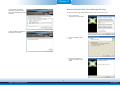
Connect the CPU fan’s cable connector to the CPU fan connector on the board. The cooling fan
will provide adequate airflow throughout the chassis to prevent overheating the CPU and board
components.
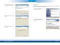
BIOS Setting
Clip
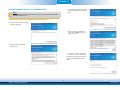
“Module Board H/W Monitor” submenu in the Advanced menu of the BIOS will display the current speed of the cooling fan. Refer to chapter 4 of the manual for more information.
Clip
15
Chapter 3 Hardware Installation
www.dfi.com