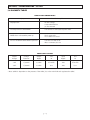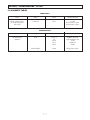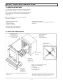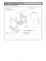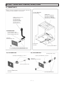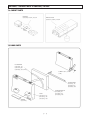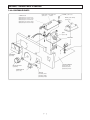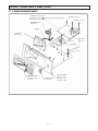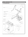
1
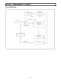
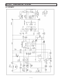
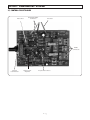
Vulcan®
Furnace
Service Manual
Models:
A-130
A550
A-1750
3-130
3-550
3-1750
3-550PD
3-550A
3-1750A
CERAMCO
®
SAFETY
SAFETY FIRST
• Don’t bypass the power cord’s ground lead with two-wire extension cords or plug adaptors.
• Don’t disconnect green/yellow safety-earth ground wire that connects the ground lug of the power receptacle to
the chassis ground.
• Don’t plug in the power cord until directed by the installation instructions.
• Don’t repair the furnace unless you are a qualified technician and know how to work with hazardous voltages.
• Don’t locate and operate the furnace in close proximity to combustible materials.
• Observe all WARNING statements. They point out situations that can cause injury or equipment damage.
• Disconnect the power cord before attempting to service.
• It is the user’s responsibility to use only cleaning agents and materials that will not result in hazards to the
equipment or material contained within.
• When replacing the main power supply cord use only a direct equivalent high-temperature cable.
• When replacing the main fuse use only a direct equivalent.
TABLE OF CONTENTS
SECTION 1
CIRCUIT DESCRIPTION
1.1
1.2
1.2.1
1.2.2
1.2.3
1.2.4
A-CONTROL
INTRODUCTION ..........................................1-1
CIRCUIT DESCRIPTION ..............................1-1
Analog Meter Readout ...............................1-1
Front Panel Controls ..................................1-1
Muffle Control ...........................................1-1
Power Supply ............................................1-1
SECTION 2
TROUBLESHOOTING
2.1
2.2
2.3
2.3.1
2.3.2
2.3.3
2.4
2.5
2.6
2.7
2.8
5.3.3
5.3.4
5.3.5
5.3.6
5.3.7
5.4
5.5
5.6
5.7
5.8
5.9
Peripheral Drive ........................................5-1
Motor Drive ...............................................5-1
Analog Circuitry.........................................5-1
Display Board ...........................................5-1
Fan Drive Control ......................................5-2
TROUBLESHOOTING COMPONENTS............5-2
ERROR CODES...........................................5-3
DIAGNOSTIC TABLES .................................5-4
BLOCK DIAGRAM.......................................5-8
SCHEMATICS ............................................5-9
WIRING DIAGRAM ....................................5-12
A-CONTROL
FACTORY REPAIR........................................2-1
BEFORE YOU START ...................................2-1
TROUBLESHOOTING GUIDES ......................2-1
Power Supply ............................................2-1
Analog Circuitry.........................................2-1
Triac Drive.................................................2-1
TROUBLESHOOTING COMPONENTS ............2-1
BLOCK DIAGRAM.......................................2-3
SCHEMATIC ..............................................2-4
CONTROL CIRCUIT BOARD..........................2-5
WIRING DIAGRAM .....................................2-6
SECTION 6
ADJUSTMENT/CALIBRATION3-STAGE
6.1
6.2
6.3
6.3.1
6.3.2
6.4
6.4.1
6.4.2
SCOPE .....................................................6-1
FACTORY REPAIR .......................................6-1
ADJUSTMENT/CALIBRATION .......................6-1
Temperature ............................................6-1
Door, Lift Drag Adjustment ........................6-1
CIRCUIT BOARD CALIBRATION ...................6-1
Required Test Equipment ..........................6-1
Temperature .............................................6-1
SECTION 7
SERVICE PARTS
SECTION 3
CALIBRATION
3.1
3.2
3.3
3.3.1
3.4
3.4.1
3.4.2
A-CONTROL
SCOPE ......................................................3-1
FACTORY REPAIR........................................3-1
ADJUSTMENTS...........................................3-1
Door, Lift Drag Adjustment ........................3-1
CIRCUIT BOARD CALIBRATION ...................3-1
Required Test Equipment ..........................3-1
Temperature .............................................3-1
SECTION 4
CIRCUIT DESCRIPTION
4.1
4.2
4.2.1
4.2.2
4.2.3
4.2.4
4.2.5
4.2.6
3-STAGE
INTRODUCTION
CIRCUIT DESCRIPTION .............................4-1
LCD Display Readout.................................4-1
Front Panel Control ...................................4-1
Muffle Control...........................................4-1
Power Supply............................................4-1
Motor Drive Control ...................................4-1
Fan Drive Control ......................................4-1
SECTION 5
TROUBLESHOOTING
5.1
5.2
5.2.1
5.3
5.3.1
5.3.2
3-STAGE
FACTORY REPAIR........................................5-1
BEFORE YOU START ...................................5-1
Isolating a Problem ...................................5-1
TROUBLESHOOTING GUIDES .....................5-1
Power Supply ............................................5-1
Microprocessor ........................................5-1
7.1
7.2
7.3
7.4
7.5
7.6
7.7
7.8
ORDERING INSTRUCTIONS.........................7-1
MUFFLE AND THERMOCOUPLE ...................7-1
MUFFLE (3-550 PD / AIR EXCH)...................7-2
CABINET PARTS.........................................7-3
DOOR PARTS ............................................7-4
A-CONTROLLER PARTS ..............................7-5
3-STAGE & 3-550 CONTROLLER PARTS........7-6
LIFT MECHANISM PARTS (3-550PD) ............7-7
SECTION 8
DISASSEMBLY/REASSEMBLY
8.1
8.2
8.3
8.4
8.5
8.6
8.7
8.8
8.9
8.10
8.11
8.12
8.13
8.14
8.15
CONTROL DRAWER REMOVAL.....................8-1
TRIAC........................................................8-1
MEMBRANE SWITCH..................................8-2
DISPLAY PCB ............................................8-3
A-CONTROL PCB .......................................8-4
3 STAGE CONTROL PCB .............................8-5
DOOR ASSEMBLY/ADJUSTMENT ................8-6
HEATING PLATES.......................................8-7
MUFFLE REPLACEMENT........................ .....8-8
THERMOCOUPLE (A-Control) .....................8-9
THERMOCOUPLE (3 STAGE) .......................8-9
MUFFLE REPLACEMENT(3-550 PD)........ ....8-10
THERMOCOUPLE (3-550PD) ......................8-11
POWER SWITCH .......................................8-12
POWER DOOR REPLACEMENT ...................8-13
SECTION 1 - CIRCUIT DESCRIPTION - A-CONTROL
1.1 INTRODUCTION
The purpose of this section is to familiarize the user or
service personnel with the circuit level operation of the
VULCAN. This knowledge is necessary to aid in troubleshooting of a unit's failure and may also allow the
user to gain greater insight into the VULCAN’s versatility
for particular applications. A detailed description is
given for the following circuit functions:
•
•
•
•
Analog Meter Readout
Front Panel Controls
Muffle Control
Power Supply
To slow down the heatup time of the muffle (RP2 set
clockwise and muffle is at low temperature) a rate
control potentiometer (RP3) has been added to the
circuitry. A sawtooth signal from pin2 of U2 is compared
with a fixed reference voltage which can be set by RP3.
As the sawtooth voltage exceeds the value of the fixed
reference voltage, amplifier U3 produces a negative
output which in turn increases the thermocouple signal
output from U1 and Vpin3 of U2 and is now more
negative than Vref, thus the triac output pulses stop.
1.2.4 POWER SUPPLY
The rectified supply current (D2) is zener regulated to
8.6V and biased by dropping resistors R11, R12.
The positive voltage to U1 and U2 is provided by a 6.8V
zener diode D1.
1.2 CIRCUIT DESCRIPTION
1.2.1 ANALOG METER READOUT
NOTES:
The Type K thermocouple which extends from the back
of the muffle is directly connected to an analog meter
which provides the operator with the present muffle
temperature. The yellow lead of the thermocouple is
connected to the + input of the meter.
________________________________________________
________________________________________________
________________________________________________
1.2.2 FRONT PANEL CONTROLS
The power on/off switch provides AC line voltage to the
furnace if the door switch is closed, while the setpoint
potentiometer (10K) provides the electronics with a
reference voltage which determines the final muffle
temperature.
________________________________________________
________________________________________________
________________________________________________
1.2.3 MUFFLE CONTROL
The muffle is controlled by means of a triac. This muffle
triac may be activated anytime when the AC cycle goes
through zero, and once activated it will only be opened
again when the AC sine wave passes through 0
volts.The triac is controlled by a Zero Voltage Switch
(integrated circuit U2) and is configured as a
proportional controller.Trigger pulses are generated
when the comparator detects Vpin3 is above the Vref.
The sensed temperature from the amplified
thermocouple signal is then lower than the set value of
RP2. As Vpin3 is near in value of Vref, a proportional
control takes over, i. e. power is delivered by bursts to
the load.
________________________________________________
________________________________________________
________________________________________________
________________________________________________
________________________________________________
________________________________________________
________________________________________________
________________________________________________
I
________________________________________________
________________________________________________
t
T
Load Current - Proportional Control
________________________________________________
________________________________________________
1–1
SECTION 2 - TROUBLESHOOTING - A-CONTROL
2.3.3 TRIAC DRIVE
2.1 FACTORY REPAIR
A current pulse from U2 pin 6 of about 60mA will turn
on the gate of the muffle triac which in turn will then
carry the full load current. The voltage across the triac
is now at 1-2 Vac. In order to comply with norms limiting
the frequency at which a kW size load may be connected
to the main line (fluorescent tubes "flickering") a
proportional temperature control is provided by means
of burst firing the triac.
DENTSPLY Ceramco maintains a factory repair
department for those customers not possessing the
necessary personnel or test equipment to maintain the
VULCAN. If a unit is returned to the factory for
calibration or repair, a detailed description of the
specific problem should be attached to minimize
turnaround time. Call factory for PR number before
shipping at 1-800-835-6639.
NOTES:
2.2 BEFORE YOU START
Since no troubleshooting guide can possibly cover all
the potential problems, the aim of this guide is to give a
methodology which, if applied consistently, will lead to
the problem area. Therefore , it is necessary to
familiarize yourself with the VULCAN by reviewing the
functional description in conjunction with the
schematic. Successful troubleshooting depends upon
understanding the circuit operation.
________________________________________________
________________________________________________
________________________________________________
________________________________________________
________________________________________________
WARNING:
With covers removed, dangerous voltage points may
be exposed. Contact with any of these points could
cause serious injury.
2.4 TROUBLESHOOTING COMPONENTS
2.4.1 DIODE
2.3 TROUBLESHOOTING GUIDES
A diode (except a zener) is defective if there is greater
than 1 Vdc (typically 0.7 Vdc) forward voltage across it.
WARNING:
When measuring voltages use battery operated test
equipment unless an isolation transformer is
connected between circuit input and AC line.
2.4.2 OPERATIONAL AMPLIFIER
Rectifier diodes D2 and D3 convert the AC line voltage to
a DC voltage, while resistors R11, R12 reduce the current
flow thru the 8.6V internal zener diode of U2 and the
6.8V external zener diode D1. Capacitors C1 and C5 filter
the rectified voltages. Most of the circuit's current
consumption is taken up by the triac gate drive.
Generally, the “+” and “-” inputs of an operational
amplifier will have less than 15 mV voltage difference
when operating under normal conditions. If the output
voltage stays at maximum positive (typically 1/3 of the
supply voltage), the “+” input voltage should be more
positive than the “-” input voltage. If the output voltage
stays at minimum (typically 1-5 mV), the “-” input
voltage should be more positive than the “+” input
voltage.
2.3.2 ANALOG CIRCUITRY
2.4.3 TRIAC
The thermocouple voltage which ranges from 0-45mV
(25°C - 1100°C) is multiplied by amplifier U1
approximately 100 times (depending on the setting of
potentiometer RP1) and added to the negative setpoint
voltage from RP2. A sawtooth voltage signal is
generated by U2 from a constant current source
charging capacitor C4. The value of C4 determines the
burst period of the triac output (typically 8 seconds).
The triac gate output pulse current is about 60mA. The
triac is triggered in quadrants II and III. Synchronization
is provided by resistor R10. Its value determines the
trigger pulse length.
The gate to power line return voltage under load
measures typically 1-2 Vac, while the MT2 to return
voltage measures between 1.3-1.8 Vac. A triac without
connections and no power applied can be checked for a
go-no go condition with an ohmmeter. The gate to MT1
resistance for a power triac (20-40A) should be between
50 and 100 ohms; there should be infinite resistance
between MT1 and MT2.
2.3.1 POWER SUPPLY
2.4.4 CAPACITOR
Shorted capacitors have 0V across their terminals.
Open capacitors can be located by using a good capacitor connected in parallel with the capacitor under test
and observing the resulting effect.
2–1
SECTION 2 - TROUBLESHOOTING - A-CONTROL
Leaking capacitors will often have a decreased voltage
across their terminals.
NOTES:
________________________________________________
________________________________________________
________________________________________________
________________________________________________
________________________________________________
2–2
SECTION 2 - TROUBLESHOOTING - A-CONTROL
2.5 BLOCK DIAGRAM
120/240V
60/50Hz
Line
Power Supply
D1,C1,R11
Return
Cabinet
+6.8V
-8.6V
Set Point Pot
Comparator,
Power Supply,
Triac Driver
U2
Rate Control Pot
Amplifier U1
Thermocouple
Power Triac
25A, 400V
Feedback
Muffle
2–3
SECTION 2 - TROUBLESHOOTING - A-CONTROL
2.6 SCHEMATIC
2–4
SECTION 2 - TROUBLESHOOTING - A-CONTROL
2.7 CONTROL CIRCUIT BOARD
Rate Control
Temperature Meter
Connection
Triac Gate
Muffle
Connections
Setpoint
Potentiometer
Thermocouple
Amplifier
Proportional Control iC
2–5
SECTION 2 - TROUBLESHOOTING - A-CONTROL
2.8 WIRING DIAGRAM
230V
LINE CORD
230V
RECEPTACLE
NOTE: A1750 - 250V,20A
LINE CORD
WHT
WHT
120V LINE
CORD
GRN/YELL
BLK
CABINET
GND
230V
A-1750
230V HOOK UP
HEATING
PLATE
RIAC HEATSINK
C
P1
120V HOOK
UP AND
1750
MUFFLE
TRIAC
D
DOOR SAFETY
SWITCH
P6
WHT
BLK
WHT
CONTROL
DRAWER
GND
RED
TAN
GRN/YELL
P1
P5
ROUTE ALL MUFFLE
WIRES THRU HERE
AC1
THERMOCOUPLE
AC2
MT2
MT1
WHT/BLK
A
BLK
B
TOP
TERMINALS
ORN
GATE
A
B
RED
YELL
POWER SWITCH
SETPOINT ADJUST
C
D
ANALOG PANEL METER
RELAY FOR A-1750 ONLY
2–6
A
B
SECTION 3 - ADJUSTMENT/CALIBRATION - A-CONTROL
3.1 SCOPE
3.4 CIRCUIT BOARD CALIBRATION
This section gives the procedures to be used for the
calibration and specification verification of the VULCAN.
The furnace specifications are given in the Owner &
Operator’s Manual.
Calibration of the VULCAN circuit board is performed in
one single step.
3.4.1 REQUIRED TEST EQUIPMENT
- Multimeter
- Pot adjustment tool
3.2 FACTORY REPAIR
WARNING
With control drawer opened, dangerous voltage points
may be exposed. Contact with any of these points could
cause serious injury.
DENTSPLY Ceramco maintains a factory repair
department for those customers not possessing the
necessary personnel or test equipment to maintain the
VULCAN. If a unit is returned to the factory for
calibration or repair, a detailed description of the
specific problem should be included to minimize
turnaround time. Call factory for RMA number before
shipping at 909-.795.2461.
3.4.2 TEMPERATURE
Disconnect the power cord from the wall outlet and
open the control drawer. Connect the black lead of the
ohmmeter to the red thermocouple connection on
temperature meter. Touch the red lead of the ohmmeter
to the leg with a circle on R13. Adjust RP1 to read 1060
ohms on the ohmmeter.
3.3 ADJUSTMENTS
3.3.1 DOOR, LIFT DRAG ADJUSTMENT
The lift drag force is controlled by a set of friction
washers on each of the upper pivot arms. If the drag
becomes too stiff (too hard to open and close furnace)
or too loose an adjustment can be made using the
following procedure:
On models A-550 rated at 120V the potentiometer RP3
should be adjusted the following way:
Touch the black lead of the ohmmeter to pin 3 of U3 and
the red lead to the leg of R14, see figure 7.2. Adjust RP3
to read between 19 and 20 Kohm on the ohmmeter. This
adjustment limits the amount of current going thru the
muffle by about 15% in order to comply with safety
agency rulings. For all other models RP3 should be fully
clockwise.
TOOLS: 5/32" Allen Wrench
- Turn the allen head screws on the upper side of the
furnace either clockwise to tighten or counterclockwise
to loosen the drag force.
NOTE:
Equal adjustment should be made on each side. Turn
screws only 1/6 of a revolution at a time when making
adjustment.
Connect DMM to PCB as shown in Figure 7-2:
a. For all 120V Units: Adjust RP# to read 19K-20K Ohms
b. For all 220V-240V Units: Adjust RP3 Fully Clockwise (CW)
Black Lead to U3
Pin 3 Here
Front of Control Drawer
As an alternate circuit board calibration, without the use
of an ohmmeter, bring the furnace temperature to the
desired level. At steady state temperature insert a
thermocouple, connected to a temperature monitor, into
the exhaust opening of the furnace and after
stabilization read the muffle temperature. Compare this
reading with the temperature meter reading of the
furnace. In several steps adjust RP1 to obtain equal
readings. Allow ample time between adjustment steps
since only a few watts are added/subtracted which each
adjustment of RP1.
Red Lead to
R14 Here
Figure 7-2
3–1
SECTION 4 - CIRCUIT DESCRIPTION - 3-STAGE
4.2.4 POWER SUPPLY
4.1 INTRODUCTION
The purpose of this section is to familiarize the user or
service personnel with the circuit level operation of the
VULCAN. This knowledge is necessary to aid in troubleshooting of a unit's failure and may also allow the
user to gain greater insight into the VULCAN’s versatility
for particular applications. A detailed description is
given for the following circuit functions:
* Display Readout
* Front Panel Control
* Muffle Control
* Power Supply
* Motor Drive Control (option for 3-Stage)
*Temperature Measurement
One DC power supply voltage is generated on the
control circuit board +5V.
4.2.4.1 +12V SUPPLY
The +12 VDC is generated from 15 watt switching power
supply mounted onto the main control PC board.
4.2.4.2 +5V SUPPLY
Refer to schematic, page 5-9. DC voltage from the output
of the switching power supply is used by the +5V linear
regulator U3 to generate the +5V. The capacitor C21
provides additional filtering. The 1.23V reference diode
D1 generate their outputs from this supply.
4.2.5 MOTOR DRIVE CONTROL (3-550 PD)
The +12VDC motor which moves the door vertically is
controlled by a 16 pin motor controller/driver I.C. This
I.C. provides all necessary functions for a complete
closed loop system. A two wire cable connects the
motor to the 1 Amp H-bridge switch on the I.C. The
microprocessor (U9) activates the H-switch through two
input pins. If both are low the motor will turn in one
direction, if both are high the motor turns in the
opposite direction. A third pin sends a signal from the
motor controller/driver I.C. to the microprocessor when
the motor has stalled (up or down position).
The muffle temperature is derived from a Thermocouple
(type "K") which generates an output voltage of up to
50mV. This feedback signal is then manipulated by the
electronics to control the muffle temperature.
4.2 CIRCUIT DESCRIPTION 3-STAGE
4.2.1 LCD DISPLAY READOUT
The display board converts serial data from the
microprocessor to 8-bit parallel data. Each byte
transferred is either a command or a data byte
depending on the state of the two control bits RS and E
(DIS ENA). The 16 character LCD module is controlled by
the microprocessor via its Serial Peripheral Interface
(SPI) port. The display is updated every 0.5 sec or when
a corresponding front panel key has been activated.
4.2.6 FAN DRIVE CONTROL 3-550A/1750A
The air exchange fan is controlled by means of the front
panel membrane switch. Speed selections are from
0 - 9 (0 is off and 9 is highest speed). Speed 1 selection
changes the air in the muffle twice a minute.
4.2.2 FRONT PANEL CONTROL
NOTES:
The power on/off switch switches the AC line voltage.
The membrane switches are arranged in a 8x4 matrix.
The microprocessor scans the entire matrix every 50
msec by setting one column at a time to a logic 0 and
then reading the rows. Once a contact closure has been
detected this value is stored.
________________________________________________
________________________________________________
________________________________________________
4.2.3 MUFFLE CONTROL
The microprocessor (U9) sends a serial digital signal to an
octal peripheral driver (U6) which in turn converts and
latches it to parallel data. This data is then used to drive
several peripheral devices. U9 is connected to an opto
isolator (U7). The isolator's output is connected to the
gate of the muffle triac. The muffle triac may be activated
anytime during an AC cycle, but once activated it can only
be opened when the AC sine wave passes through 0
volts. U9 accesses U7 0.5 msec before zero crossing to
turn the triac off. At this time a value calculated by the
control routine determines how much time should elapse
before the triac is turned on again.
________________________________________________
4–1
SECTION 5 - TROUBLESHOOTING - 3-STAGE
5.1 FACTORY REPAIR
5.3 TROUBLESHOOTING GUIDES
DENTSPLY Ceramco maintains a factory repair
department for those customers not possessing the
necessary personnel or test equipment to maintain the
VULCAN. If a unit is returned to the factory for
calibration or repair, a detailed description of the
specific problem should be attached to minimize
turnaround time. Call factory for PR number before
shipping at 1-800-835-6639.
5.3.1 POWER SUPPLY
5.2 BEFORE YOU START
Since no troubleshooting guide can possibly cover all
the potential problems, the aim of this guide is to give a
methodology which, if applied consistently, will lead to
the problem area. Therefore , it is necessary to
familiarize yourself with the VULCAN by reviewing the
functional description and the detailed circuit
description (Section 4) in conjunction with the
schematics (Section 5). Successful troubleshooting
depends upon understanding the circuit operation
within each functional block as well as the block
relationships.
WARNING
With covers removed, dangerous voltage points may be
exposed. Contact with any of these points could cause
serious injury.
To determine a faulty power supply use the table on
page 5-3. To troubleshoot a faulty power supply use the
procedures listed on page 5-4. If the desired results are
obtained in each of the steps in the tables, replace D43,
U9 or U7 as appropriate.
5.3.2 MICROPROCESSOR
Generally, when the furnace is totally nonfunctional,
i.e., display is unintelligible, no display, random relay
clicking, no key response, or the front panel LED’s stay
on at power up, the problem is in the microprocessor
section. However, before troubleshooting this section,
check the appropriate dedicated circuits for correct
operation. Detailed reading of the circuit description is
also very important. See page 5-5 to troubleshoot the
microprocessor.
5.3.3 PERIPHERAL DRIVE
The peripheral driver U6 is accessed at every line
voltage zero crossing by the microprocessor. The logic
state of the eight output drivers, Y0 -Y7, is latched into
the shift register at time t0 on the high to low transition
of SIOE. Input data present at the SI input is clocked
into the shift register on the high to low transition of
SCLK. See page 5-6 to troubleshoot the peripheral
driver.
The intent of this section is to provide the information to
return the VULCAN to proper operation. Information is
divided into two parts. Part one contains the overall
furnace troubleshooting block diagram which is useful
in isolating defective blocks within the furnace. Part two
consists of a series of circuit guides , one for each block
shown in the block diagram, that provides settings and
measurements for troubleshooting an individual block.
Also, each circuit guide references related schematics
and circuit descriptions. Inspect the components,
wiring and circuit boards of the VULCAN for damage.
Finally, ensure that the fuses are intact and the internal
power supplies are good.
5.3.4 MOTOR DRIVE (OPTIONAL ACCESSORY)
5.2.1 ISOLATING A PROBLEM
5.3.6 DISPLAY BOARD
To successfully troubleshoot this furnace, the symptoms
must first be identified, the faulty block isolated, then
analyzed, and finally the defective component located
and replaced.
After the block is isolated, refer to the appropriate
functional circuit guide.
The motor driver U8 is accessed by the microprocessor
to lift or lower the door. U8 provides a feedback to the
microprocessor to indicate an overcurrent condition
which is set at approximately 1.00Amp by resistor R3.
See page 5-6 to troubleshoot the motor driver.
5.3.5 ANALOG CIRCUITRY
The reference voltages used to control temperature and
compare voltage signals are derived from the output of
U1-7 (+5V) and D1. See schematics for troubleshooting
individual components. See page 5-6 to troubleshoot
the analog circuitry.
Serial data present on the input of U1-14 and U2-2 is
transfered to the shift register on the logic “0” to logic
“1” transition of the Clock input pulse. Information
present at any register of U1 is transferred to its
respective latch when the Strobe is high (U1-7). A serial
to parallel conversion takes place. As long as the Strobe
is held high (“1”) the latches will accept new data. The
LCD display module will accept valid data on D0 - D7
when the Enable (J1-6) goes from a high to low
transition. See page 5-7 to troubleshoot the display
circuit board.
The circuit guide provides some but not necessarily all
of the possible failure modes for a particular circuit.
Where applicable, a furnace setup procedure is given to
help isolate the problem for a particular failure mode.
5–1
SECTION 5 - TROUBLESHOOTING - 3-STAGE
5.3.7 FAN DRIVE (OPTIONAL ACCESSORY)
5.4.3 TRIAC
The 12V DC fan is controlled by a FET device which is
activated by the microprcessor. At its highest setting
(9), the fan receives the full 12V DC. At lower settings
the fan receives +12V pulses, to reduce the rpm's.
The gate to power line return voltage (K1) under load
measures typically 1-2 Vac, while the MT2 to return
voltage measures between 1.3-1.8 Vac.
A triac without connections can be checked for a go-no
go condition with an ohmmeter. The gate to MT1
resistance for a power triac (20-40A) should be between
50 and 100 ohms; there should be infinite resistance
between MT1 and MT2.
5.4 TROUBLESHOOTING COMPONENTS
5.4.1 DIODE
A diode (except a zener) is defective if there is greater
than 1 Vdc (typically 0.7 Vdc) forward voltage across it.
5.4.4 CAPACITOR
5.4.2 OPERATIONAL AMPLIFIER
Generally the “+” and “-” inputs of an operational
amplifier will have less than 15 mV voltage difference
when operating under normal conditions. (U1). When
the output of the amplifier is connected to the “-” input
(voltage follower connection), the output should be the
same voltage as the “+” input voltage; otherwise, the
amplifier is defective.
If the output voltage stays at maximum positive
(typically 1/3 of the supply voltage), the “+” input
voltage should be more postitive than the “-” input
voltage.
Shorted capacitors have 0V across their terminals.
Open capacitors can be located by using a good
capacitor connected in parallel with the capacitor under
test and observing the resulting effect. Leaking
capacitors will often have a decreased voltage across
their terminals.
5.4.5 LOGIC LEVELS
Microprocessor:
High
Low
+3.5 0.0 -
+5.0V
+1.0V
74LSXXX:
High
Low
+2.0 0.0 -
+5.0V
+0.5V
4XXX (CMOS):
High
Low
+3.5 0.0 -
+5.0V
+1.5V
5–2
SECTION 5 - TROUBLESHOOTING - 3-STAGE
5.5 ERROR CODES
ERR 1
MUFFLE OVER TEMPERATURE
The controller monitored a temperature above
°C. This could mean a faulty thermocouple (mV
reading too high) or an erratic thermocouple
performance (the temperature readout is not
stable at elevated temperatures).
ERR 2
OPEN TC DETECTED
To check for open TC, turn power to furnace off
and short TC input terminals. Turn power back
on. If ERR 2 disappears, then replace TC.
Possible solutions:
Change PCB if problem persists.
ERR 3
TMAX OVER TEMP
The controller monitored a temperature above
Tmax + 20°C. This could mean:
* The Tmax was set up too low for this program
* The destination temperature is relatively low
compared to the programmed heat rate, eg.
too much temperature overshoot.
ERR 8
EEPROM READ/WRITE ERROR
(APPLIES TO 9493980 ONLY)
Program parameters entered during the idle
mode are transferred and stored in a 16K-bit
Electrically Erasable Programmable Read Only
Memory (EEPROM) device. The serial data on
U10 is monitored and any abnormal behavior
from the devices’ specs is answered with an
error code. Press ENTER and check:
* Data, Clock train on U10-5,6
* Replace device
ERR 19
NO LINE FREQUENCY DETECTED
(APPLIES TO 9493980 ONLY)
* Check U1 A-1, 100 or 120 Hz pulse train
* Remove Power
5–3
SECTION 5 - TROUBLESHOOTING - 3-STAGE
5.6 DIAGNOSTIC TABLES
FURNACE SETUP COMMON ERRORS
Symptom
Possible Setup Error
Display blank
No line voltage
Power switch failure
J8 disconnected
No Setup functions after ENTER
Furnace was in start cycle at power down
Muffle does not heat after power up
Not in start cycle
Door switch not closed
No door movement after switch is pressed
Furnace is in TEST mode
Motor connector J5 loose
POWER SUPPLY VOLTAGES
Output
Voltage
Voltage
Tolerance
Output
Ripple
Test
At
Input
Ripple
Test
At
+12V
+/-350mV
0.02Vac
PT1 & PT4
3Vac
PT1 & PT4
+ 5V*
+/-250mV
0.02Vac
U3-3
3Vac
U3-1
* Note: +5VDC is dependent on the presents of the 12VDC, U3 on the main PC Board regulates the +5VDC.
5–4
SECTION 5 - TROUBLESHOOTING - 3-STAGE
5.6 DIAGNOSTIC TABLES
POWER SUPPLY
Fault
Setup
Check
Results desired
No DC output and no
DC to U11-2 (15-30V)
PT1 to PT4
Power off
Fuse
< 1 ohm
Not shorted or open
Not shorted or open
MICROPROCESSOR
Fault
Setup
Check
Results desired
Nonfunctional
operation
N/A
U9-3, 2
X1
U9-26
U9-9
U9-10
4.9MHz, sinusoid
approximately 0-4V
>4.5V
waveform
+5VDC
Power Off/On
Listen
Relay clicks,Sonar
5–5
SECTION 5 - TROUBLESHOOTING - 3-STAGE
5.6 DIAGNOSTIC TABLES
PERIPHERAL DRIVE CIRCUIT
Fault
Setup
Check
All Y outputs
high
N/A
U6-1, 2, 6
Results desired
No stuck bits
Turn furnace
Off then On
Display/
LED's
No Error codes
Display OK
Turn furnace
Off
D2, D3, D4, D6
Not shorted or open
MOTOR DRIVE CIRCUIT
Fault
Setup
Check
Results desired
No door up or down
when switch is activated
Furnace in idle
Disconnect J5
Turn furnace on
Activate switch
Activate switch
Turn furnace off
Turn furnace on
U8-16
U8-10-15
+12 VDC
U13-15
digital high
Motor switch
Other keys respond
Stall
current
> 550 mA at up
or down
At up or down
position
Add mA meter in
series at J5
5–6
SECTION 5 - TROUBLESHOOTING - 3-STAGE
5.6 DIAGNOSTIC TABLES
ANALOG CIRCUITRY
Fault
Setup
Check
Results desired
Muffle heats but
display shows
same temperature
N/A
YELL2
U4
D1
TC yellow connected
Gain approx. 20
1.23V
Erratic temperature
display
N/A
D1
U4-11 & 12
1.23V stable
DC stable
Temperature drift
Hi T = 960°C
RED
39-40mV stable
U4-13
mV stable
(.2mV/°C ambient
increase typical)
Reconnect
TC wires
No Err2 at elevated
temperatures
Turn furnace off
DISPLAY BOARD
Fault
Setup
Check
Results desired
LCD dots are all
on or off at power up
Furnace in idle
J8-1
+5V
J4-8
Tight fit
Perform power up
Front Panel
N/A
J8-4
LED's turn off one
by one
+12V
One LED does not come on
Turn furnace off
LED
Not open or
shorted
LCD display is darker
Turn furnace off
Temperature on
panel
Less than 40°C
Turn furnace on
Temperature on
panel
LCD lighter shade
No LED's light up
5–7
SECTION 5 - TROUBLESHOOTING - 3-STAGE
5.7 BLOCK DIAGRAM
Switching
Power Supply
+12V
90-264V
60/50Hz
Pg 5-9
U1, U2
Thermocouple
Zero Crossing
AMP U1
U9
U4
Multiplexed A/D
U8
Microprocessor
M
Pg 5-11
D1 + RT1
Cold Jct.
Motor Drive
Pg 5-11
Ref Temp
Pg 5-10
U6
Peripheral
Drive
Membrane Switches
Pg 5-9
K1, K2
Display Board
Muffle Relays
Pg 5-9
16 Character LCD
Triac driver
U2
U1
LED Driver
(10)
Serial to
Parallel
Pg 5-9
Sonar
5–8
SECTION 5 - TROUBLESHOOTING - 3-STAGE
5.8 SCHEMATICS
POWER SUPPLY
5– 9
SECTION 5 - TROUBLESHOOTING - 3-STAGE
5.8 SCHEMATICS
TEMPERATURE CIRCUIT
LCD DISPLAY CIRCUIT
5 – 10
SECTION 5 - TROUBLESHOOTING - 3-STAGE
5.8 SCHEMATICS
MICROPROCESSOR CIRCUIT
5 – 11A
SECTION 5 - TROUBLESHOOTING - 3-STAGE
5.8 SCHEMATICS
5 – 11B
SECTION 5 - TROUBLESHOOTING - 3-STAGE, PD, A
5.9 WIRING DIAGRAM
5 – 12
SECTION 6 - ADJUSTMENT/CALIBRATION - 3-STAGE
6.3.2 DOOR, LIFT DRAG ADJUSTMENT
6.1 SCOPE
This section gives the procedures to be used for the
calibration and specification verification of the VULCAN.
The furnace specifications are given in the Owner &
Operator’s Manual.
The lift drag force is controlled by a set of friction
washers on each of the upper pivot arms A wave spring
should maintain a relatively constant force even after
several thousand cycles. If the drag becomes too stiff
(too hard to open and close furnace) or too loose an
adjustment can be made using the following procedure:
TOOLS REQUIRED: 5/32" Allen Wrench
6.2 FACTORY REPAIR
- Turn the allen head screws on the upper side of the
furnace either clockwise to tighten or counterclockwise
to loosen the drag force.
DENTSPLY Ceramco maintains a factory repair
department for those customers not possessing the
necessary personnel or test equipment to maintain the
VULCAN. If a unit is returned to the factory for
calibration or repair, a detailed description of the
specific problem should be included to minimize
turnaround time. Call factory for PR number before
shipping at 1-800-835-6639.
Note: Equal adjustment should be made on each side.
Turn screws only 1/6 of a revolution at a time when
making adjustment.
6.4 CIRCUIT BOARD CALIBRATION
6.3 ADJUSTMENT/CALIBRATION
Calibration of the VULCAN circuit board is performed in
two steps: Software and hardware.
6.3.1 TEMPERATURE
To verify the muffle temperature at a given setpoint
insert the tip of a temperature probe into the exhaust
opening far enough to reach the center of the muffle.
Connect the other end of the probe to a temperature
meter and let the meter reading stabilize. Once a steady
reading is obtained on the temperature meter divide the
setpoint (display) temperature by the meter
temperature and multiply the result by the current Tcal
value. The result will be the new Tcal temperature.
Example:
The temperature meter shows a reading of 520°C at a
setpoint of 500°C. The Tcal temperature in the setup
mode shows 1000°C.
The new setup temperature Tcal is now found by the
following calculation:
500°C
520°C
Tcal = .961 x1000 = 961°C
Note: Abort the cycle before turning off the furnace.
This is the new Tcal temperature. Turn the furnace off
and then on again, wait for Setup? on the display and
press ENTER until Tcal = 1000°C appears. Key in 961 and
press ENTER.
6–1
WARNING
With control drawer opened, dangerous voltage points
may be exposed. Contact with any of these points could
cause serious injury.
WARNING
Observe antistatic procedures when touching
circuit board components which can be damaged by
static electricity.
SECTION 7 - SERVICE PARTS - A-CONTROL & 3-STAGE
7.1 ORDERING INSTRUCTIONS
To order parts, select the part number required from the
exploded view drawings on page 7.1. through page 7.6.
The 130, 550, 1750 numbers refer to the particular size of
furnace where the part number is different depending
on the size.
When ordering parts please have the following
information available:
1. Serial number of furnace.
2. Date purchased.
3. Purchased where.
4. Symptom of failure.
5. Part number of replacement part.
6. Preferred method of shipment.
Hardware Kit: 9493454
(Contains a selection of the fasteners used in the
furnaces.)
7.2 MUFFLE AND THERMOCOUPLE
HEATING PLATE ASSY
New 9493426*, 130
230V (9493364), 550
100, 120V (9493470), 550
(9493392), 1750
MUFFLE INSULATION
(9493341), 130
(9493361), 550
(Factory Repair), 1750
THERMOCOUPLE
(9493342) 130, 550
(9491747) 1750
MUFFLE SPRINGS
(9390705)
FLOOR TRAY
(9353053), 130
(9353057), 550
(9353060, 1750
FRONT PANEL
(9493315), 130
(9493355), 550
(9493385), 1750
NOTE: Part shape and assembly will vary between the three
furnace sizes.
MUFFLE ASSY COMPLETE:(Includes muffle
insulation, and 2 heating plates)
(9493422), 130
230V (9493423), 550
100, 120V (9493471), 550
(Factory Repair), 1750
* Note: 9493340 was replace with 9493426. IF your model -130
was built before August 2011 you need to replace both muffle
plates. Also order replacement fuse part no. 9320137.
7–1
SECTION 7 - SERVICE PARTS - 3-550A & 3-550PD
7.3 MUFFLE (3-550 PD & AIR EXCH)
MUFFLE INSULATION
(9493780), 550 PD
HEATING PLATE ASSY
230V (9493364), 550 PD
100, 120V (9493470), 550PD
THERMOCOUPLE
(9493342) 550 PD
FLOOR TRAY
(9353057), 550
MUFFLE ASSY COMPLETE:(Includes muffle
insulation, and 2 heating plates)
FRONT PANEL
(9493808), 550 PD
230V (9493778), 550 PD
100, 120V (9493779), 550 PD
(9493996), 550A
(Factory Repair), 1750A
7–2
SECTION 7 - SERVICE PARTS - A-CONTROL, 3-STAGE, 3-550PD
7.4 CABINET PARTS
NOTE: To convert to configurations shown, 9495115 - Retrofit Kit, is
available for furnaces built prior to S/N 0626xxx.
(9493534) REAR PANEL
3-550PD FURNACE
CABINET ASSY
(9493320) 130 FURNACES
(9493354) 550 FURNACES
(9493384) 1750 FURNACES
(9493807) 3-550 PD FURNACE
POWER CORD (120 & 230V)
(9390115) 130, 120V
(9309118) 230V US
(9309117) 230V EURO
(9493653) 1750 EURO
(9409131) 1750 US
(9390118) 550, 120V
120V SOCKET ASSY
(9302072) FUSE, 20 Amp
(9320136) FUSE, 16 Amp, 120V
(9320137) FUSE, 12 Amp, 120V
(9494462)
ADAPTER PLATE, 120V
SOCKET ASSY.
LOCATION
(9493338) DOOR SWITCH
For - 130 Models (9494462) ADAPTER PLATE, 120V
For - 550 Models (9493822) ADAPTER PLATE, 120V
130, 230V SOCKET ASSY
550, 230V SOCKET ASSY
(9320197) FUSE, 10 amp
(9492995) SOCKET ASSY., 200/240V
(9495104) SOCKET ASSY., 200/240V
(9495099)
ADAPTER PLATE, 200/240V
(9320069) FUSE, 10 amp
(9492996) ADAPTER PLATE,
200/240V
(9311017A) FUSE HOLDER
7– 3
SECTION 7 - SERVICE PARTS - A-CONTROL, 3-STAGE
7.4 CABINET PARTS
FAN ASSY
(9493986) 3-550A, 3-1750A
FAN DUCT ASSY
(9493970) 3-550A, 3-1750A
7.5 DOOR PARTS
DOOR SPRING
(9493368), 130
(9493908), 550
(9492754), 1750 (2 PL)
SCREW 10-32 x .50 KEP
(4 PL)
DOOR BOTTOM
(9493313), 130
(9493351), 550
(9493381), 1750
HANDLE
(9390246)
DOOR
(9493321) , 130
(9493350), 550
(9493380), 1750
7– 4
DOOR INSULATION
(9493325), 130
(9493365), 550
(9493393), 1750
SECTION 7 - SERVICE PARTS - A-CONTROL
7.6 A- CONTROLLER PARTS
CONTROL PCB
(R9493348) 100-120V A-130
(R9493449) 200-240V A-130
(R9493349) 100-120V A-550
(R9493450) 200-240V A-550
(R9493451) 200-240V A-1750
FUSE (20A) - S/N 9525 and
9320072
earlier
SCREW, 6-32 x .375
RELAY, (1750 ONLY)
(9320075)
TRIAC
(9303015)
HEATSINK
PYROMETER
(9390451)
CONTROL DRAWER
(9493316) A-130
(9493356) A-550
(9493386) A-1750
KNOB, SET POINT
(9355026)
POWER SWITCH
(9306038)
OVERLAY
(9354229) A-130
(9354230) A-550
(9354231) A-1750
7– 5
SECTION 7 - SERVICE PARTS - 3-STAGE, 3-550PD
7.7 3-STAGE CONTROLLER PARTS
s
CONTROL PCB, 3-550 PD,A
(R9493446) 100-125V
Replaced by R9495232 (Not Shown)
(R9493447) 200-240V
SCREW, 6-32 x .375
SCREW, 6-32 x 1.75
TERMINAL BLOCK
(9390487)
TC WIRES
DISPLAY PCB
(R9493347)
TRIAC
(9303015)
HEATSINK
MEMBRANE SWITCH
(9494063, 3-550A,
3-1750A)
POWER SWITCH
(9306038)
7– 6
CONTROL DRAWER
(9493376, 3-130)
(9493379, 3-550)
(9493387, 3-1750)
FUSE (1A)
9320071
SECTION 7 - SERVICE PARTS - 3-550PD
7.8 LIFT MECHANISM PARTS
NUT, 1/4-20 HEX
SCREW, 10-32 SEM
BRACE
(9493363)
PIVOT ARM
BRACKET, MOTOR LINKAGE
(9493532)
BOLT, SHOULDER .375
SCREW, #8-32 SEM
BRACKET, MOTOR
(9493362)
SCREW #8 X.375
SCREW, #8 X .50
BRACKET, SPRING
MOTOR POWER DOOR
(9493777)
SCREW, 1/4-20
SPRING
(9356016)
LNUT 1/4-20 HEX NYLOK
7–7
SECTION 8 - DISASSEMBLY/REASSEMBLY - 3-STAGE
8.1 CONTROL DRAWER REMOVAL
8.2 TRIAC
TOOLS:
TOOLS:
Phillips #2 screwdriver
Phillips #2 screwdriver, 1/4" nut driver, needle nose pliers
- To gain access to the electrical components and most
other service jobs, removal of the control drawer is
required.
8.2.1:
Follow steps 8.1.1 through 8.1.2 of CONTROL DRAWER
REMOVAL
WARNING:
Disconnect power cord from wall outlet
before attempting to service the furnace.
8.2.2:
Disconnect wires from triac located at the rear center
of the control drawer.(use pliers to assist)
8.2.3:
Remove 2 nuts and lift triac off heatsink.
8.1.1:
Remove 2 screws from bottom front of the furnace
Use Heatsink (white)
compound from old triac.
8.2.4:
Replace with new triac and note orientation.
Insert screwdriver
if needed
8.1.2:
8.2.5:
Slide control drawer towards you.
Note: A bladed screwdriver may be needed
Connect wires to triac according to Wiring Diagram 2.9
(A Control) or 5.9 (3 Stage) Make sure connections are tight
8–1
SECTION 8 - DISASSEMBLY/REASSEMBLY - 3-STAGE
8.3 MEMBRANE SWITCH
TOOLS:
Phillips screwdriver
Knife of other sharp edged device
8.3.1:
Follow steps 8.1.1 through 8.1.2 of CONTROL DRAWER
REMOVAL
Control PCB
Membrane Switch
Control Drawer
8.3.5:
Place the new membrane switch by locating the
bottom edge against the bottom of the recess.
Membrane Switch
8.3.2:
Control PCB
Disconnect ribbon cable at control PCB
DOT
Membrane Switch
8.3.6:
Connect ribbon connector
8.3.3:
Peel off membrane switch (Use knife if needed).
8.3.4:
Membrane Switch
Control Drawer
Clean front panel surface with isopropyl alcohol.
Allow to dry thoroughly.
8– 2
SECTION 8 - DISASSEMBLY/REASSEMBLY - 3-STAGE
8.4 DISPLAY PCB
TOOLS: Phillips screwdriver
CAUTION!
Use proper ESD grounding techniques when handling
electronic components
8.4.1:
Follow steps 8.1.1 through 8.1.2 of CONTROL DRAWER
REMOVAL
8.4.5:
Connect grey ribbon connector. Bend away from
Display PCB so it won't cut into ribbon.
8.4.2:
Disconnect grey ribbon connector.
8.4.3:
Remove from snap-on standoffs.
8.4.4:
Replace with new Display PCB.
8– 3
SECTION 8 - DISASSEMBLY/REASSEMBLY - A-CONTROL
8.5 A-CONTROL PCB
TOOLS:
Phillips screwdriver
Needle nose pliers
3/8" nut driver or wrench
1/4" nut driver
13 mm nut driver or pliers
CAUTION!
Use proper ESD grounding techniques when handling
electronic component
8.5.5:
Remove knob by pulling out and nut (13mm nut driver or
pliers).
8.5.1:
Follow steps 8.1.1 through 8.1.2 of CONTROL DRAWER
REMOVAL.
Remove
muffle
wires
AC1
AC2
MT1
MT2
8.5.2:
Disconnect wires AC1, AC2, MT1, MT2 and 4 muffle wires
from power board.
8.5.3:
Disconnect orange wire from triac.
Orange
8.5.6:
Remove 2 screws.
Pyrometer
Reverse steps for reassembly.
Red from PCB
Red from Muffle
7.8
Fig. G
Top
View
CAUTION! Do not overtighten nut
Yellow from PCB
Yellow from Muffle
8.5.4:
Disconnect wires from pyrometer.
8– 4
SECTION 8 - DISASSEMBLY/REASSEMBLY - 3-STAGE
8.6A 3 STAGE CONTROL PCB - 9493980
TOOLS:
Phillips screwdriver, Slotted screwdriver, Needle nose pliers
CAUTION!
Use proper ESD grounding techniques when handling
electronic components
8.6.6: Remove thermocouple wires
8.6.1: Follow steps 8.1.1 through 8.1.2 of CONTROL DRAWER
REMOVAL.
DOT
8.6.2: Disconnect wires from power switch.
8.6.7: Remove 5 screws.
8.6.3: Disconnect ribbon connectors.
8.6.8: Squeeze plastic standoff and lift circuit board.
8.6.4: Remove relay and door switch wires.
8.6.9: Replace with new circuit board. Tighten
5 screws. Follow wiring diagram 5.9 on page 5-12.
8.6.5: Disconnect wires from triac.
8– 5
SECTION 8 - DISASSEMBLY/REASSEMBLY
8.6B 3 STAGE CONTROL PCB – 9495232
CAUTION!
Use proper ESD grounding techniques when handling
components
TOOLS:
Phillips & Slotted Screwdrivers, Needle Nose Pliers
Follow steps 8.1.1 through 8.1.2 of Control Drawer
REMOVAL
Figure 1 - Disconnect wires from
Power Switch
Figure 2 - Disconnect Ribbon Cables
Figure 3 - Remove Relay Wires
Figure 4 -Remove Door Switch Wires
Figure 5 - Remove Wire From Triac
Figure 6 - Remove Thermocouple
Wires
Figure 7 - Remove 4 Screws from PCB
Figure 8 - Squeeze standoff with
needle nose pliers & remove PCB
Figure 9 - New PCB Replacement
Figure 10 - Insert PCB in standoff,
tighten 4 Screws
Figure 11 - Follow Steps #1 thru
#6 for PCB Connections
8 – 5A
SECTION 8 - DISASSEMBLY/REASSEMBLY
8.7 DOOR ASSEMBLY/ ADJUSTMENT
TOOLS:
5/32 Allen wrench
Phillips head screwdriver
If the door feels too stiff or too loose when lifting up and
down, a tension adjustment can be made from the outside.
8.7.4: If door or door insulation needs replacement,
remove the 4 screws on bottom of door (step 5.7.2) and slide
from slide out assy.
8.7.1: If door tension is too loose tighten the screw on each
side until the desired tension is reached. If too tight, loosen
screw.
8.7.5: Remove 2 screws and slide out door insulation
and spring. If door is to be replaced, remove 2 screws
holding handle.
8.7.2: If door insulation is rubbing against cabinet, loosen
the 2 screws on each side of door.
8.7.6: Replace with new insulation or door by reversing steps
8.7.4 - 8.7.5.
8.7.7: Set spacing as described in section 8.7.3. Important!
Screws must be torqued to 25-30 in-lbs.
8.7.3: Rotate door out from cabinet and tighten 4 screws.
Check to make sure that rope contacts muffle lip when
closed and insulation clears cabinet when lifted.
8– 6
SECTION 8 - DISASSEMBLY/REASSEMBLY
8.8 HEATING PLATES
TOOLS: Phillips head screwdriver
Small putty knife
Note: Like the headlights on a car, if one heating
plate burns out, the other will likely burn out soon.
Therefore, it would be advisable to replace both
plates at once.
WARNING:
Disconnect power from the wall outlet before
attempting to service the furnace!
Brake bond with
putty knife
rotate in
8.8.3: Pull out bad plate(s) (Rotate bottom of plate
toward center of muffle). Be careful when pulling leads
thru holes in muffle.
8.8.1 Follow steps 8.1.1 - 8.1.2 of CONTROL DRAWER
REMOVAL.
A-CONTROL
(130, 550) 100, 120V HOOK UP
(1750) 230V
Black marked
lead
(130, 550)
230V HOOK UP
P1
TAN
P1
P6
feed wires thru
bushings (one wire
per bushing)
P6
Black marked
lead
3-STAGE
(130, 550) 100, 120V MUFFLE
WIRING (1750), 230V
(130, 550) 230V
MUFFLE WIRING
8.8.4: Replace with new plate(s). There are brass
bushings located in the heatshield below the muffle
holes. Cut tie wraps located on terminals' insulation.
Slide the piece of insulating sleeve (provided) over the
existing ones and tie wrap at 1" below the heat shield. It
may take a few attempts to locate this hole with the
muffle terminal
TAN W/BLK MARK
8.8.1: Disconnect muffle wires from plate(s) to be
replaced. (refer to wiring diagram 2.9 for A-Control and
5.9 for 3-stage control.)
Apply white adhesive
(optional)
8.8.5: Optional: a syringe of ceramic adhesive is
provided to hold plates secure to sides. Stuff newspaper
in muffle until adhesive sets (1 hr). There will be some
movement of the plates without the adhesive.
8.8.6: Connect muffle wires from plate(s) to control PCB.
Refer to wiring diagram 2.8 for A-Control or 5.9 for 3 stage
control. (See step 8.8.1)
8.8.7: Install floor tray
8.8.2: Remove floor tray
8.8.8: Install control drawer by reversing steps 8.1.1 8.8.5
8– 7
SECTION 8 - DISASSEMBLY/REASSEMBLY
8.9 COMPLETE MUFFLE REPLACEMENT
TOOLS: Phillips head screwdriver; small flat head
screwdriver; needle nose pliers
WARNING:
Disconnect power from the wall outlet before
attempting to service the furnace!
8.9.1: Follow steps 8.1.1 - 8.1.2 of CONTROL DRAWER
REMOVAL.
A-CONTROL
100, 120V HOOK UP
8.9.6: Pull/pry out muffle assy (with attached front
panel) from wraparound
230V HOOK UP
P1
P6
TAN
REMOVE SCREW
P1
3 - Stage
100, 120V
MUFFLE
WIRING
TAN W/BLK
MARK
230V MUFFLE
WIRING
8.9.7: Remove screw used to secure thermocouple
and pull thermocouple from muffle
TAN
TAN W/BLK MARK
REMOVE SPRINGS
8.9.2: Disconnect muffle wires. (Refer to wiring diagram 2.8
for A-Control and 5.9 for 3 stage control.)
8.9.8: Remove muffle retaining springs with needle
nose pliers. CAUTION: WEAR GLOVES AND EYE
PROTECTION!
REMOVE SCREWS
8.9.9: Remove muffle assy
8.9.3: Remove 5 or 6 screws on the front top of the
furnace. Remove exhaust port
8.9.4: Open door
muffle wires must pass thru
brass bushings (4 pl)
REMOVE SCREWS
8.9.5: Remove two screws (one each side)
8.9.10: Replace with new muffle assy by reversing
steps 8.9.1 - 8.9.9. Make sure that muffle wires pass
thru brass bushings in heatshield
8– 8
SECTION 8 - DISASSEMBLY/REASSEMBLY
8.11 THERMOCOUPLE (3 STAGE CONTROL)
TOOLS: bladed screwdriver
phillips head screwdriver
1/4" nutdriver
bracket
WARNING:
Disconnect power from the wall outlet
before attempting to service the furnace!
Wraparound
Front Panel
8.9.11: Front panel must insert into offset bracket in
wraparound
8.11.1: Follow steps 8.1.1 - 8.1.2 of control drawer removal
8.9.12: Check muffle resistance to verify wiring is
correct before securing control drawer:
100V
120V
A-130, 3-130 11.5 ohms 11.5 ohms
A-550, 3-550
8 ohms
8 ohms
A-1750, 3-1750
8.11.2: Follow steps 8.9.3 - 8.9.7 from previous page for
muffle replacement for furnaces without a rear access panel.
Note: All 1750 furnaces and all furnaces with S/N date codes
after 9701 will have rear access panel so that muffle will not
need to be removed to service thermocouple (see step
8.11.6 for details).
200-240V
32 ohms
24 ohms
12 ohms
8.10 THERMOCOUPLE (A-CONTROL)
remove nut
TOOLS: bladed screwdriver phillips head screwdriver, 3/8"
nutdriver, wrench, 1/4" nutdriver
WARNING:
Disconnect power from the wall outlet
before attempting to service the furnace!
8.10.1: Follow steps 8.1.1 - 8.1.2 of control drawer removal
8.10.2: Follow steps 8.9.3 - 8.9.7 from previous page for
muffle replacement for furnaces without a rear access panel.
Note: All 1750 furnaces and all furnaces with S/N date codes
after 9701 will have rear access panel so that muffle will not
need to be removed to service thermocouple (see step
8.11.6 for details).
8.11.3: Remove nut which holds thermocouple to
control drawer.
Pyrometer
Red from PCB
Red from Muffle
7.8
Fig. G
Top
View
Yellow from PCB
Yellow from Muffle
8.10.3: Disconnect thermocouple from pyrometer
remove and replace nut
red
yel
8.11.4: Disconnect thermocouple from circuit board
red
8.11.5: Replace with new thermocouple by reversing previous
steps 8.11.1 thru 8.11.4
yel
meter
8.10.4: Remove nut. Replace thermocouple by reversing
previous steps and replace nut.
8– 9
SECTION 8 - DISASSEMBLY/REASSEMBLY
8.12 COMPLETE MUFFLE REPLACEMENT
TOOLS: Phillips head screwdriver; bladed screw
driver; needle nose pliers
8.12.1: Follow steps 8.1.1 - 8.1.2 of CONTROL DRAWER
REMOVAL.
REMOVE SCREWS
8.12.2: Close door and remove 6 screws on the front
top of the furnace. Remove exhaust port
8.12.6: Pull/pry out muffle assy (with attached front
panel) from wraparound
REMOVE SCREWS
REMOVE SCREWS
8.12.3: Close door and remove six screws
(three each side)
WARNING:
Disconnect power from the wall outlet before
attempting to service the furnace!
100, 120V
MUFFLE
WIRING
TAN W/BLK
MARK
8.12.7: Remove screw used to secure thermocouple
and pull thermocouple from muffle
230V MUFFLE
WIRING
TAN
TAN W/BLK MARK
8.12.4: Disconnect muffle wires. (Refer to wiring
diagram 5.9).
8.12.8: Remove muffle assy by removing 10 screw.
muffle wires must pass thru
brass bushings (4 pl)
8.12.5: Disconnect thermocouple from circuit board
8.12.9: Replace with new muffle assy by reversing steps
8.12.1 - 8.12.8. Make sure that muffle wires pass thru
brass bushings in heatshield
8 – 10
SECTION 8 - DISASSEMBLY/REASSEMBLY
8.13 THERMOCOUPLE (3-550 PD)
TOOLS: bladed screwdriver
phillips head screwdriver
1/4" nutdriver
bracket
WARNING:
Disconnect power from the wall outlet
before attempting to service the furnace!
Wraparound
Front Panel
8.12.10: Front panel must insert into offset bracket in
wraparound
8.13.1: Follow steps 8.1.1 - 8.1.2 of control drawer removal
8.12.11: Check muffle resistance to verify wiring is correct
before securing control drawer:
3-550 PD
100v
8 ohms
120v
8 ohms
200-240v
24 ohms
remove nut
8.13.2: Remove nut which holds thermocouple to
control drawer.
8.13.3: Disconnect thermocouple from circuit board
8 – 11
SECTION 8 - DISASSEMBLY/REASSEMBLY
8.14 POWER SWITCH
Remove 2 screws
TOOLS: Slotted screwdriver
8.14.1: Follow steps 8.1.1 through 8.1.2 of CONTROL DRAWER
REMOVAL
8.14.2: Disconnect switch wires
8.13.3: Remove the 2 screws which support rear panel.
8.14.3: Remove switch by pressing in tabs.
8.13.4: Remove screw used to secure thermocouple and
pull thermocouple from muffle. Pull thermocouple wire
through brass grommet.
8.13.5: Replace with new thermocouple by reversing previous
steps 8.11.1 thru 8.11.4
8.14.4: Press in new switch
8.14.5: Connect switch wires
8 – 12
SECTION 8 - DISASSEMBLY/REASSEMBLY
8.15 POWER DOOR MOTOR REPLACEMENT
8.15.5: Disconnect wires (Female quick connect
terminals) from motor.
Disconnect wires
8.15.1: Slide control drawer forward using steps 8.1.1
and 8.1.2
8.15.2: Slide muffle assembly forward using steps
8.1.3, 8.9.4, 8.9.5 and 8.9.6 (approximately 5
inches).
8.15.3: Remove the 2 screws which support rear panel.
Remove 2 screws
8.15.6: Remove (4) screws to free motor
Remove 2 screws
Remove 2 screws
8.15.4: Remove the 2 screws to free motor linkage bracket
from base.
Remove 2 screws
8.15.7: Remove (4) screws and shoulder bolt to free
motor from motor bracket.
Remove 4 screws
Remove shoulder bolt
8.15.8: Replace with new motor by reversing previous
steps 8.15.1 thru 8.15.7.
8 – 13
PRODUCT SERVICE:
Three methods of product service are available:
• Telephone assistance available at the number listed below.
• Return the unit for servicing using the instructions below.
BEFORE RETURNING THE UNIT:
• Call DENTSPLY for a PR (Product Return) number. This is used to track and identify your unit. Equipment received
without this number may not be identifiable.
• If you do not have the original packaging, please request replacement packaging to ensure the unit is not
damaged in shipment.
• Secure top section in down position using original rubber bands supplied with the original packaging.
• Equipment damaged in shipment as a result of improper packing may not be paid by the carrier.
DENTSPLY will not be responsible for damages resulting from improper packing.
Ship prepaid to:
DENTSPLY Ceramco
ATTN: Equipment Repair
PR Number__________________
470 West College Ave.
York, PA 17404 USA
Phone: 800.835.6639 Option #1 (US Customers)
717.849.4502 (International Customers)
Fax: 909.795.5268
Email: [email protected]
CERAMCO
®
Distributed by:
Manufactured For:
DENTSPLY International Inc. DENTSPLY Canada
161 Vinyl Court
DENTSPLY Ceramco
Woodbridge, Ontario
570 West College Ave.
L4L 4A3
York, PA 17405-0872
905-968-5374
1-800-243-1942
prosthetics.dentsply.com or dentsply.com
Printed in U.S.A.
9363049 Rev. 12/11