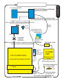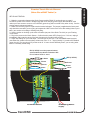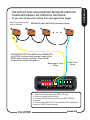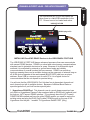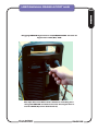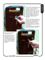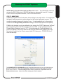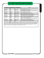
1
DTHC IV -SETUP/INSTALL MANUAL for CommandCNC Rev0.1 part2 1. DCP-01 Digital Current Probe Install & setup 2. Grounding Practices for plasma noise suppression 3. Troubleshooting Charts 4. FT-01 Feather Touch (revised) 5. Installing and using HYT-Connect RS485 serial Option for Hypertherm Disclaimer: This is a preliminary manual and may contain typos and references the older CandCNC products or software. +15V CandCNC -15V FeatherTouch ACT CAL Plasma Unit Ohmic Sensor TEST 20 - 125A Workclamp Lead DC AMPS Power CLAMP CandCNC DIGITAL CURRENT PROBE SENSE OUT WARNING Use with Floating Torch Only IN Model DCP-01 CandCNC PAGE 1 ADDENDUM SETTING UP OPTIONS ADDENDUM Digital Current Probe Block diagram of DCP-01 DCP-01 Block Diagram Connections RAW ARC VOLTAGE PLASMA UNIT TORCH SWITCH DCP Interconnect cable RJ45 (CAT5) to DTHC II Moduler Input connector DCP Workpiece Clamp Good connection to the workpiece with clamp is essential for proper operation of the THC CandCNC PAGE 2 Physical install and hookup DCP-01 Digital Current Probe uses the existing THC SENSOR (rev 14 or above) and slips over the Plasma System Workclamp lead wire to provide DC amp feedback to the DTHC and to the MACH screen. The following series of photos shows the DCP being hooked up to a plasma cutter. Start by removing the ground clamp from your plasma work clamp. If it has a large ring terminal on the end where it attaches to the clamp you will need remove the ring terminal and replace it with a new one after you push it through the DCP unit. Plasma Unit End ADDENDUM Digital Current Probe Digital Current Probe Installation Model DCP-01 Clamp End Right Hand Strain Relief Loosen the cable strain relief/clamps on each end of the box by twisting the retainer nut counterclockwise viewed from the end. The strain relief has an internal collar that clamps down on the wire the more it is tightened. Straighten the wire as much as possible and start feeding it from the right hand side. Clamp End Left hand Strain Relief Plasma Unit End Cable passes through center of DCP-01 CandCNC Push the wire through gently. If it hangs try rotating the wire and pushing but do not force it. There is a round hole in the hall probe inside the box that the wire has to pass through. It is located close to the right side of the unit. If you have problems getting the wire to go though pull the wire out and remove the 4 screws holding the top and remove the top and the PCB with the Hall Probe (see next page). Thread the wire though the right side strain relief and pull enough through so you can thread the Hall Probe on the card and then over and out of the left side strain relief. PAGE 3 Workclamp Lead Wire goes through Hall Probe center as shown. Top shown flipped 180 degrees. NOTE: Your DCP-01 unit will ship with an interconnect cable to connect it to the PWM Module. If you remove the top cover pull carefully to prevent breaking or disconnecting the interconnect cable. If it comes loose it fits in a RJ11 jack on the board. The cable is a standard 6 conductor flat DATA cable (straight through wiring) not a Phone cable When you have the Workclamp lead wire threaded through the box, hand tighten the outside nuts on each strain relief until it is tight around the cable. It is important that each end is sealed to keep out plasma dust and smoke. Position the DCP-01 along the cable close to the plasma unit and in a place it will not get stepped on, crushed or can be dragged across the floor if you decide to move your plasma unit or use it manually in the shop. The enclosure is sealed and rugged but it can be damaged by excessive abuse. PAGE 4 CandCNC ADDENDUM Digital Current Probe Digital Current Probe Installation Model DCP-01 SETUP, TESTING and CALIBRATION of the DCP-01 DIGITAL CURRENT PROBE Do the following steps in order: 1. Connect the DCP-01 interface cable (RJ11 flat silver) to the THC SENSOR PWM front panel jack labeled DCP. You should get a positive “click” as the cable is seated. Removing the cable should require releasing the locking pin. 2. If you are connecting up your DTHC II and THC SENSOR PWM for the first time, make the connections to the THC SENSOR PWM Module and the CAT5 cable back to the DTHC II module front Panel connector on the MP3000-DTHC or the BladeRunner Dragon Cut. Do this BEFORE you make the Tip Volts (Arc volts) connection or the TORCH SWITCH. You can run some tests on the THC SENSOR Card and the DCP without having the plasma unit turned on or the Tip Volts present. CandCNC PAGE 5 ADDENDUM Digital Current Probe Digital Current Probe Setup & Testing Model DCP-01 Digital Current Probe Digital Current Probe Setup & Testing Model DCP-01 4. Start CommandCNC on the controller PC and load the profile and screen set for the DTHC. If this is the first time you have used the DTHC and CommandCNC you should have had CommandCNC loaded and setup. If you do not, STOP! Go back to the CommandCNC-DTHCIV Manual and first setup CommandCNC and get your table moving and the proper CommandCNC profile loaded for your system. Readout of DC Cut Current when using the DCP-01 Digital Current Probe. This will not display a value if you do not have the DCP01 connected and working. It’s important that you have gone through the DTHCIV setup in this manual FIRST and that you have confirmed that it is working properly. 5. Power up the MP3600-DTHCIV or the BladeRunner (or your Plazpak + DTHC) so the DTHC module has power. The first thing you should see is that the +15 LED and - 15 LED on the front of the DCP lights up. The ACT (activity) LED will NOT be on. 6. Bring CommandCNC out of reset. On any unit with our ESP smart power controller (including BladeRunners) you MUST have the DC power to the motors on to come out of reset. At this stage you should have CommandCNC setup, running and know how to come out 7. Make sure that the DTHC module is communicating with CommandCNC. The DTHC ONLINE LED should be ON (green) . The TORCH VOLTS comes from the DTHC across the PC serial RS485 port connection via the C3 Bus 4 Port Hub to CommandCNC. Without the serial communications you will not get Torch Volts and you will not be able to see TORCH AMPS. PAGE 6 ADDENDUM Digital Current Probe Model DCP-01 8. Once you have determined the DTHC passes self-test then locate the small hole in the front of the DCP unit (marked CAL and TEST). You will need a small screwdriver or probe tip (paperclip?). You will feel the button click. Push it once to turn on the TEST/CAL function. When it is active the ACT LED (yellow) will flash. TO TURN OFF TEST/CAL MODE on the DCP01 push the recessed CAL/Test button once and the ACT LED should stop flashing and the TORCH AMPS readout should return to 0 Calibration/Test Button (recessed) 9.. While you are in TEST/CAL mode (LED blinking) the TORCH AMPS should display a value. If you are installing a DCP on an existing product with a DTHC the calibration could be off so the number you see could be anything from ___ to ____. If your unit displays 100 amps as shown then you continue on to final testing and CUT PROFILE Setup. IF YOUR CURRENT IS NOT 100 you will need to proceed to the CALIBRATION SECTION. CALIBRATION of the DCP-01 Use this section any time you put the unit into TEST/CAL and the displayed value in the TORCH APMS readout is NOT 100 as shown. 1. To calibrate the DTHC module to the DCP-01 you must have access to the top of the DTHC Expansion Module. Refer to your product manual to identify and access the DTHC module. It is the small PCB card behind the panel on all CandCNC units where the CAT5 cable from the PWM Sensor plugs in. In most cases all you have to do to gain access is remove the top cover (MP3600-DTHC) or the front panel (BladeRunner AIO). Use the photos below to find and identify the DTHC card and the correct adjustment point for the DCP. CAUTION: there are two identical pots (variable resistors) in the card. One is the DCP calibration pot. The other is the TORCH VOLTS calibration pot and is set at the factory DO NOT ADJUST THE WRONG POT. IF YOU ACCIDENTLY CHANGE THE TORCH VOLTS (wrong pot) you will throw your DTHC unit out of calibration and you will need to run the TEST/CAL sequence on the THC SENSOR PWM module and reset the displayed volts. NOTE: SOME later rev’s of the DTHC II module may not have the arc volts calibration pot. If it does not exist then ignore the above procedure. Check the photos. Study the board orientation and MAKE SURE you are adjusting the pot. This calibration should only have to be done once so take the time to do it right. DCP Calibration (Cont) CandCNC PAGE 7 ADDENDUM Digital Current Probe Calibration DCP calibration is set at the factory. Only do this if the test shows it to be off by more than 2 amps. 1. DTHCIV EXPANION MODULE. Located above the UBOB III card in most CandCNC products. Ribbon cable connecting DTHC IV down to UBOB card may cover adjustment pots. If so, gently move it out of the way. Do not unplug the ribbon cable or the card will be disabled. 2. Using the diagram below and with the DCP in the TEST/CAL mode (LED flashing) adjust the DCP calibration pot while watching the TORCH AMPS DRO in the CommandCNC screen. Adjust the pot until the value displayed is 100 AMPs. Your calibration procedure is complete! 16 pin header (plug) for DTHC to UBOB Cable Four wide cable is for UBOB cards prior to REV 15 Set JP4 and JP5 ON (jumpered) for REV15 UBOB . OFF for earlier versions TORCH VOLTS Calibration DO NOT CHQANGE THIS SETTING! ! DCP Calibration POT Factory set for 100A test NO FRONT PANEL RS485 JACK RESET CandCNC PAGE 8 Digital Current Probe Model DCP-01 OPERATION of the DTHCII with the DCP-01. The primary purpose of the DCP-01 is to give the operator real time feedback of the actual Cut Current. Using the settings in the Cut Profile you can set fault points (based on a percentage of the variance from the current preset value) to warn the operator if cut current is too high or too low. The ACT LED on the front of the DCP-01 (when not in Test/Cal mode) will light up anytime the detected current is above 20A. It’s just a visual indicator that the DCP-01 is reading current. If the LED lights when you fire the torch and have a valid arc and you do not see the Current displayed on the TORCH AMPS DRO on the CommandCNC screen then go back through the test and calibration section. If you see cut current out of range or get a Current Fault then check the work clamp connection, the current setting on the plasma unit, the consumables, the Cut Current setting in the Cut Profile (stored settings) and determine why the current is not what it should be. It’s important to understand that the Preset Cut Current(AMPS) does NOT set the cutting current UNLESS you have the full TAP options with a Hypertherm models 65 thru 125 and the Hyt-Connect RS485 SIM Kit Option. Only the manual adjustment on the plasma unit sets that value. The DCP-01 just tells you what the cut current REALLY is at the cut and tells you if the value is not what you have set in the specific Cut Profile you are running. This LED comes on any time detected current is 20A or greater PAGE 9 PC wCommandCNC MP3600-DTHC/Bladeruner/Plazpak Interface-Control Box ADDENDUM Grounding practices to reduce noise and increase safety Note THC Sensor Card shielded cable is not connected to any ground in the control box Do NOT Ground PC or Controllers to Earth Ground Rod. Controllers will reference themselves to power ground through their AC lines Digital Signal “clean ground” Total isolation from Plasma Side Ground PWM MODULE Controller Cabinet X NO LOCAL COMMON GROUNDs Divided Volts Analog THC Sensor Card MP3000 and UBOB have built in isolation on all inputs from the table to prevent noise transfer and ground loops Tabel I/O Card (limits, home Aux relay) CNC PLASMA TABLE Use ground strap to gantry from table PLASMA UNIT Attached to metal Chassis #10 to #4 Ga heavy wire Gantry Ground Rod or Metal pole in earth ground “Dirty” Ground Ground runs should be less than 10’ Grounding plate #10 to #4 Ga heavy STRANDED wire CandCNC PAGE117 10 Page: 1. DTHC does strange things after a pierce (TIP SAVER locks on or tip plunges to the metal.) 2. UP and DOWN (LED’s) not coming on (no Z movement). DTHC settings are wrong (wrong PRESET VOLTS). Pierce delay too long DTHC Delay in CUT PROFILE too SHORT. Arc OK not working. DTHC not working (run selftest). CommandCNC inputs not working. 3. UP & DOWN LEDs work but no Z movement. DTHCIV Z motor tuning wrong 4. Z moves but erratically or loses steps. 5. UP or DOWN LED is on but Z stops moving (won’t go further down or up). Torch won’t cut low enough or high enough even though the UP or DOWN is on and THC Button is ON 6. Z DRO does not agree with actual height at the end of a cut. 7. Torch pierces at wrong height. 8. Torch cuts too Low/High. UP and Down and Z is working. 9. TIP SAVER comes on and stays on (it is normal for the TIP SAVER to flash on/off especially at the end of a cut or if the feed rate has slowed down. Only make changes if the cut quality is poor. Z motor tuning wrong. THC RATE setting in CommandCNC is too high. THC Corrections (Max and Min) are set too low/high. (settings tab in CommandCNC). NOTE: MAX and MIN settings are in “units”. If you are running in MM units you need to change both settings by a factor of 25.4 Wrong set of macros for the DTHCIV and M5 macro is wrong Pierce height in G-code (from CAM) is set wrong. Touch-off values (switch Offset) are wrong. Z is losing steps during a cut (see #6) PRESET VOLTS is wrong for the material, tip and feed rate you are using. Preset needs to be adjusted in 1 volt increments and in the same direction as the error. Raise PRESET value to raise the torch. Lower PRESET VOLTS value to lower the torch. DO NOT GUESS AT A VALUE! Run the manual cut test to establish the proper PRESET VOLTS value OR run the SMART-KUT option (one time) if all of the pierce heights and beginning cut height are correct. TORCH VOLTS is above the PRESET. Turn off the TIP SAVER or increase the percentage in the CUT PROFILE and try the cut. If it holds the correct height then either increase the THC Delay in the cut profile (NOT CommandCNC) or increase the Tip Saver percentage in the CUT PROFILE. CandCNC PAGE 11 ADDENDUM Troubleshooting DTHC Problems. 10. Torch oscillates wildly UP and DOWN while cutting. Torch is overshooting. Use the DTHC Settings tab in the CommandCNC Cut Profiles section (page 49) and lower the DTHC Tracking and DTHC Sensitivity until the oscillations stop. 11. Torch slowly rises UP while cutting Check Torch Volts reading. IF it is above the PRESET VOLTS then the DOWN LED should be on. Also see the TIP SAVER locking on issue. 12. DTHC works fine sometimes and then does not other times using the same parameters. Possible noise problem. Make sure you have your table and plasma well grounded with a local ground rod. Try not to run your PC and Controller out of the same subpanel as the plasma. keep the grounds for each side separated locally. 13 Torch runs for a while then shuts off while cutting or does not stay lit after the pierce. Check the Indicator LED on the THC SENSOR card for the TORCH ON (relay) It should remain ON steady. If the torch still turns off (with it on) then the problem is with a connection (torch switch terminals or a problem at the torch. Do’s and Don’ts DO run the manual cut test and record the conditions you see including the LED indications. DO make sure you understand that the setups for touch-off, pierce height and cut height are working correctly. DO have the results of any testing ready for the support person. DO take the time to understand the basic concepts of how an ARC VOLTAGE THC (like the DTHC) works. DO realize there are external conditions and torch problems that can effect the DTHC. DO follow all of the grounding rules for the plasma. HF start units need extra attention to proper grounding for reliable operation. DO understand the relationships of Torch Volts, Torch AMPS, feed rate and air pressure/quality in plasma cutting. DO NOT assume there is an electronics problem until you have eliminated ALL possible problems of incorrect settings and things like consumables and air. DO NOT attempt to run plasma without the proper CommandCNC Profile (XML) loaded. Must be a CandCNC profile or a copy from our profiles. DO NOT call for support with vague descriptions or having not tested to a point. DO NOT make changes in the CommandCNC config to the base profile. Use a Clone copy and then only make one change at a time. The pin settings (mappings) are complex for our CandCNC PAGE 12 ADDENDUM ADDENDUM Troubleshooting DTHC Problems. FT-01 FeatherTouch Ohmic Sensor for use with CandCNC BladerRunner Dragon-Cut , BladeRunner Ether-Cut, MP3000-DTHCII, MP3100-DTHCIV MP3500 and Plazpak. REV 5 Manual 1/15/14 CandCNC FeatherTouch Ohmic Sensor WARNING Use with Floating Torch Only Power SENSE OUT IN To Torch Tip (Ohmic tab) 1 #2 pin blocked 4 3 2 To PLATE (Machine Frame) 1 Z home Common + DC LIMITS - DC Old Touch Switch COM Old Touch Switch NC 4 OUT 6 5 4 321 3 2 1 21 Z HOME NC COM + DC LIMITS - DC Limit String Z IN Switch Plate Tip (WC) This manual contains new connection suggestions for the FT-01 based on previous manuals. If you already have an FT-01 installed and working you should review this section and determine if you should make changes to the installation CandCNC PAGE 13 ADDENDUM FT-01 FEATHER TOUCH Ohmic Sensor (Option) It has been brought to our attention that with the old touch-off switch wired to the table I/O limits input as per the previous manuals, the switch does NOT stop motion if the Z is a homing move and the FT-01 fails to sense. In this manual we have changed where the Z safety switch is connected so it now functions as an E-stop rather than a limit. The previous labeled LIMITS wire (Green) in the UTP cable is now no longer connected to the 5 wide connector but is connected as shown. Connecting up the old TOUCH-OFF switch (Z Safety Switch) 1. You should check your Z safety switch and make sure it can be wired as Normally Closed. That means there is conduction between the COM and the NC terminal when the switch is not activated and it OPENS (no conduction) when the switch is activated (Tripped). Use an ohmeter or continuity tester to check the switch. THE E-STOP INPUT SIGNAL IN CommandCNC CANNOT BE CHANGED to make it work with a Normally open. There are other switches in the EPO circuit (in series ). 2. When you strip jacket off the UTP cable to expose the individual wires take off enough so you can make the green LIMIT wire about 3 to 4 inches longer than the others. 3. Strip back about 1/4” of insulation off the green wire and apply a .250 Crimp-on terminal to the exposed wires. 4. Remove the factory supplied jumper wire across the EPO (E-Stop) tabs on the Table I/O card. 5. Temporally plug the LIMITS wire to the EPO terminal as shown in the illustration. Measure so the remaining wires in the UTP will reach the header fo the 5 pin connector and cut them off. 6. Unplug the Limits wire and strip each wire in the UTP cable so about 3/16” is exposed and insert them in the screw terminal openings in the 5 pin connector as shown. It is important that the insulation is off back far enough that the exposed wires are making good contact with the metal contacts in the screw terminal but that the bare wires do not stick out far enough that they can touch each other. Poor wiring on this plug is the leading cause of problems with the FT-01 not working. 7. Once you have the 5 wide plug wired insert it into the header on the board as shown and reconnect the Green Limits wire over to the OUTSIDE EPO TAB (closest to the edge with the other TABS) tab as shown. To test the EPO part of the install power everything up and take CommandCNC out of RESET. IF you cannot get CommandCNC to come out of reset and you have an “External E-STOP Event “ error flash in the diagnostics screen than the Z safety is either not wired as Normally Closed or there is a wiring problem with the 5 wide connector. PAGE 14 Page: 121 CandCNC ADDENDUM IMPORTANT INFORMATION: 8. To test if the EPO is still working temporarily short across the two EPO pins and make sure you can come out of RESET . In systems with an ESP or ESPII power supply from CandCNC (BladeRunners, Plazpaks,) the Motor DC poser MUST be ON before you can come out of RESET. 9. You MUST have the jumper in place on the FT-01 module of LIMIT STRING or you must have a string on Normally Closed switches into these inputs. 3. The previous “LIMIT” switches on your system will become E-STOP switches when wired in through the FT-01. If want to keep them as LIMITS you will need to wire the two ends of the string with one end tied to any of the Table I/O common TABS (inside row) and the other end into the old LIMITS input (center terminal) on the 5 pin connector. You will need to setup you LIMITS as before using the X++ (X limits) input. 4. It is highly recommended that you get your system moving and cutting BEFORE you add the FT-01 into the mix and start changing the E-Stop connections. CandCNC PAGE 15 ADDENDUM Connecting up the Z Safety Switch (CONT.) FeatherTouch Ohmic Sensor CandCNC 1.627" FeatherTouch Ohmic Sensor WARNING Use with Floating Torch Only Power FeatherTouch™ Ohmic Sensor for CandCNC BladeRunner. Plazpak SENSE FRONT SIDE VIEW OUT IN For REV1 & REV2 Units 2.502" MANUAL RELEASE 5 4 OUT 6 5 4 321 Z HOME + DC LIMITS NC COM - DC If your lable shows TIP as 2 and Plate as 1, it is WRONG. Use this 3 2 1 21 Limit String Z IN Switch Plate Tip (WC) The CandCNC FeatherTouch Ohmic Sensor Module is designed to work with all existing CandCNC plasma controls including all MP1000-THC, MP3000-DTHC/DTHCII, BladeRunner Dragon-Cut, and Plazpak systems. It uses an active circuit to sense the tip of the torch touching the plate (material to be cut). It is totally isolated from the normal inputs to the Table I/O. The inputs on all CandCNC interface and BoB products have always been isolated from the PC ground to both prevent spikes and surges from harming sensitive port inputs on the PC and to reject noise that might come through sharing a dirty ground. The Table I/O inputs all use the same input common and it is designed to “float” and not be attached to a circuit that has a ground connection to the table (i.e. switches and devices not connected to the table electrically). If you allow one side of the Table I/O circuit to be connected to the table side ground then the isolation is partially or completely defeated. Noise from plasma cutting is exponentially higher than from routing or milling setups and needs to be considered in any input or sensor feed to the controls. The Ohmic Touch circuit is operated from its own stand-alone power source (9 to 14VDC wall plug) and its output is opto isolated so it can maintain the integrity of the noise canceling and isolated inputs of the Table I/O. It’s sensor input is surge and voltage protected so normal plasma start and run voltages do not effect it. It offers a fairly low sense impedance and filtering to prevent false triggering. Here is a list of rules to follow to get good results: 1. Always use the Ohmic Touch with a backup sensing system that will stop down motion if the sensor fails to work. This can happen on dirty, oily, rusty or painted metal. The Floating Torch Holder (mechanical Touch-off) acts as both a mechanical shock absorber and a limit switch to protect the torch from damage. DO NOT RUN WITHOUT A BACKUP MOTION LIMIT. 2. Keep the tip of the nozzle on your torch clean and free from trash and slag. If you start to have contact problems on material that is rusty or dirty, keep a spray bottle of water handy and wet down the surface for better conduction. 3. Be careful to observe polarity when hooking up the Inputs to the Torch Tip and Plate (ground) terminals. A reversed connection can result in a false signal and possible damage if left connected wrong. 4. The DC power terminals are marked for polarity. Do NOT reverse connect a source of DC or you will damage the module. If in doubt, meter it out! The + must go in the side marked + on the label. 5. Make sure to go though the hookup and calibration to test the proper functions of the Ohmic Touch and the backup limit to stop the motion. 6. Do not attempt to use Ohmic Touch with unshielded consumables. It won’t work. Some consumables may need special shields (like the Hypertherm Fine Cut with a special Ohmic shield). 7. The Ohmic Touch is designed for use with automated plasma cutting using controls from CandCNC. We cannot support other uses or interface to outer users systems.. CandCNC PAGE123 16 Page: ADDENDUM ADDENDUM OPTION: FT-01 212 732 212 733 219 676 212 724 ADDENDUM ADDENDUM ADDENDUM HYPERTHERM PARTS FOR FeatherTouch Sensor OHMIC SENSOROhmic (FT-01) 212 734 226 763 Note: Your ohmic sensor for your torch may be different than those shown here. The objective is to have a connection to the shield at the tip of the torch and it is not connected to the body of the torch or touching the frame of the torch holder. Shield sense tab provides feedback to a compatible torch height controller before starting the cutting process. Place the shield sense tab between the cup and shield. Newer 45/65/85/105 consumables for Machine Torch Ohmic Retaining Cap Hypertherm Part # 220953 FineCut Consumables Ohmic Shield Hypertherm Part # 220948 220930 Fine Cut Nozzle Normal Fine Cut uses unshielded ring. Will not work with Ohmic Touch CandCNC PAGE 17 ADDENDUM OPTION: FT-01 ADDENDUM FeatherTouch Ohmic Sensor FeatherTouch Ohmic Sensor CandCNC FeatherTouch Ohmic Sensor Power SENSE WARNING Use with Floating Torch Only OUT IN 1 Z home Common + DC LIMITS TORCH BODY - DC #2 pin blocked Torch Holder (part of table structure) 4 3 2 1 4 Wide Pluggable Screw terminal Touch Switch COM Touch Switch NC TERM2 (PLATE) Stranded Insulated Wire size 24 -to 16ga TERM 1 Ohmic Tab Insulated Barrel (Retaining Cup) Ohmic Connection Tab (Shield Sense Tab) Mechanized Shield (TIP) Requires special Ohmic Consumable See your torch vendor for ordering. CandCNC 1. Attach the Ohmic Sensor module close to the torch mount on the Z carriage. Use a Velcro strip. 2. BE CAREFUL of POLARITY when making the connections. If the PLATE and TIP leads are connected backwards and the torch is fired possible damage to the Ohmic Sensor Module is possible. Units are not repairable. NOTE: SOME REV1 UNITS HAD THE TERMINALS MARKED WRONG ON THE LABEL SEE THE DIAGRAM ON PAGE 1 3. The PLATE lead must be connected to metal that is part of the cutting grid (where the metal to be cut is placed) Most tables are electrically connected between the gantry and table parts and the cutting grid. If your table has a separate table for cutting make sure it is attached to the gantry superstructure and torch holder via a strap or you will have to extend the PLATE wire (Term 2) down to the actual plate you are cutting. PAGE125 18 Page: OPTION: FT-01 4 OUT 6 5 4 321 3 2 1 21 Z HOME LIMITS NC blocked #2 pin COM + DC - DC Limit String Z Plate Tip (WC) IN Switch Jumper MUST be in place on installs that do not have a string of LIMITS already setup. See the instructions for more details. These Wires are not part of the cable bundle and are not supplied. Shipped Jumpered See text to use as part of string of limits NO COM U TP NC CA BL E Existing Touch-off Switch on Floating Torch Holder wire as NORMALLY CLOSED Table I/O REV 6 - 8 versions Earlier versions will work as well + DC - DC Table I/O Card Located inside BladeRunner and newer Plazpaks CandCNC NOTE: The indicators on the Table I/O card will light when the signal is active (ON) between the input terminal and the common terminal across from it (inner row). It will give you visual indication that the signal is getting to the inputs and that the Table I/O is connected to the UBOB card in the controller. PAGE 19 ADDENDUM FeatherTouch Ohmic Sensor OPTION: FT-01 TABLE I/O REV 10 w/ Ohmic Sensor Interface Card REV 10 Table I/O was released to production 2/15/13 ToUBOB 10 K4 J2 QUAD RELAY K3 D3 C1 OK D15 UP C6 ARC C4 C5 C8 LIMITS T6 D8 T19 ZHome C3 6 C9 DOWN T2 T17 T18 AHome YHome Xhome T15 T16 D6 C2 1 T9 D16 T7 D18 T3 R3 1 D10 T5 AHome D7 LIMITS T14 D5 Yhome ZHome T13 T12 D4 Xhome InsideRow COMMON Remove factory jumper. T10 DOWN 1 T20 FT-01 EPO X NC UP FT-01 PWRIN D12 J1 + This connection changed from previous manual to use old touch=off swtich in NC mode to E-Stop the system S +D Lim C its Inp ut C O Z Ho M me - 35 ft UTP Cable #2 pin blocked PO DANGER! K4 C&CNC TABLEI/O REV10 COM J17 K3OUT NO J14 R1 K4 J3 T11 Strip wires and attach plug as Shown C D EG T21 DANGER! K3 ++ D11 K3 R2 D2 5 N J4 --- K4 20A240VMAX K3 DANGER! +++ NO Com2 9 - 14VDC Floating (wallplug) 1 Shown Above: New Table I/O REV 10 table I/O card. This card is a redesign. The PORT 2 inputs are removed (not used). Jack for Ohmic Sensor is added along with the floating power input for the Ohmic Sensor Module. It uses the same cable as the previous REV 8 model with the Ohmic Sensor Interface Card. The normal Port 1 inputs and outputs are the same as the previous Table I/O cards although the exact position on the cards has changed. The card is smaller and easier to get into tight spaces. The 35 ft UTP cable is shipped with the 6 wide IDC connector attached and the other end of the cable unterminated. The 5 pin Mini Pluggable Termial is shipped un-attached to the cable so the cable is easier to thread down exiting cable routes. Cut the cable to length then strip the wires on the unterminated end and carefully wire the wire colors as shown. It is important that you get the wires oriented as shown. The 5 pin and jack are keyed so it only fits one way. Plug it in the jack first to determine the orientation. NOTE: In the cable there are 8 wires but only 5 are used. The White/Green wire and the Brown and White/Brown are NOT used. Cut them off. If you have enough length you can use them for the wires to connect your Tip and Material (plate) wires and/or your old touch-off switch. CandCNC PAGE 20 ADDENDUM FeatherTouch Ohmic Sensor ToUBOB 10 K4 J2 QUAD RELAY K3 C1 1 OK 6 C6 C9 C5 C8 ARC C3 C4 T18 AHome T16 D6 ZHome YHome Xhome T15 C2 ZHome T17 T14 D5 Yhome me LIMITS T19 Z Ho 1 D10 DOWN T6 D8 T13 T12 D4 Xhome its UP T2 Lim T9 D16 T7 D18 T3 AHome D7 T5 R3 D15 T10 LIMITS - T20 1 DOWN FT-01 EPO + UP FT-01 PWRIN D12 J1 X 5 InsideRow COMMON DANGER! K4 C&CNC TABLEI/O REV10 COM J17 K3OUT NO J14 D3 R1 K4 J3 T11 EG T21 DANGER! K3 ++ D11 K3 R2 D2 Strip wires and attach plug as Shown C D N J4 --- K4 20A240VMAX K3 DANGER! +++ NO Com2 9 - 14VDC Floating (wallplug) You can setup a bypass switch and locate it close to the operator so you can bring CommandCNC out of RESET and manually jog the axis off the switch to clear the condition. The switch needs to be a MOMENTARY type so it won’t be left on and defeat the E-STOP from the Z Safety and any LIMITS connected through the FT01. Normally Open Momentary Switch Press to Bypass E-STOP FROM Z Safety You will need to make up a 2 conductor wire and switch to fit the two .250 EPO tabs on the Table I/O The type of switch used for the Bypass is not critical as long as it is Normally Open and closed when you push it. When you release it should return to Normally Open. Most pushbutton switches are configured this way. Because the circuit is NC most of the time noise on the Bypass Switch or wires has no effect . NOTE: This can be used on any Table I/O version shown if the EPO is used for other E-STOP inputs. CandCNC PAGE 21 ADDENDUM BY-PASS OPTION SWITCH FOR E-STOP ( not included in FT-01 kit) FeatherTouch Ohmic Sensor (New CoreCNC Table I/o SETUP AND TESTING: 1. Make the connections between the Ohmic Sensor and the Table I/O card as shown on page # . . Provide DC power to the module. Modules ship with a DC wall plug power supply that should be used unless you have access to a source of FLOATING (ground neg side is not tied to any other circuit). See the section power hookups and options. 2. Make sure the wire jumper is in place at the location indicated. The jumper is applied at the factory and only should be removed if you are going to integrate the LIMIT for the touch off in with existing limits on your table (see section on hooking to existing limit string. 3. Use the section on hooking up the touch-off switch (not part of the Ohmic Touch kit) on your Floating Torch Holder. 4. Plug in the power to the Ohmic Sensor. Confirm that the power LED (Green) is on. If it is not, unplug it immediately and locate the cause of the lack of power to the module using a DVM. 5. Check the settings on your limits input. The limit input is port 8 pin 11 in most UBOB based systems. (new Ether-Cut system is an exception) At least one of the ++ or – signal (usually X--) needs to be Enabled (green check) if you are using it for just the touch off. It has to be set differently than if you are using other limits in a normally closed string. EPO (E-STOP)* must be jumpered unless external NC E-stop button is attached OR FT-01 Feather Touch is used EPO (E-STOP)* A Home Zhome Chome Yhome Bhome Xhome 1 1 Limits 1 1 1 FT-01 External INPUTS To FT-01 Module CandCNC To Wallplug Power supply PAGE 22 ADDENDUM ADDENDUM Note: Your switch pinout may be different SEPARATE LIMIT SWITCHES (Normally Closed) NO COM NC THIS SETUP PUTS THE LIMITS in the STRING INTO the E-STOP circuit and they operate as part of the ESTOP and no longer just limits. They will NOT be ignored during a Homing Move. End of Limit String Beginning of Limit String 4 OUT 6 5 4 321 3 2 1 21 Z HOME LIMITS NC COM + DC - DC Limit String Z IN Switch Tip Plate (WC) 1. Take Limit string loose from Table I/O card 2. Remove jumper on limit string 3. Put two ends of limit string into the LIMIT STRING terminals 4. Connect the LIMITS OUT wire (white in this manual) as shown to LIMITS input terminal. CandCNC PAGE 23 ADDENDUM FOR SETUPS THAT HAVE EXISTING SEPARATE LIMITS ON OTHER AXIS USING a NC STRING OF SWITCHES: (if you do not have this setup then disregard this page) RS485 4 PORT HUB - DEVICE CONNECT The USB Active (ACT) LED only comes on when there is a valid USB connection to the PC. Drivers have to be loaded and active. USB ACTIVE LED PWR Con ACT USB B plug to PC USB INSTALLING CandCNC RS485 Devices to the USB-RS485 4 PORT HUB The USB-RS485 4 PORT HUB has an advanced processor than can communicate with several RS485 devices. RS485 is a robust and noise-immune communications standard used in industrial electronics for years. Because of its differential signal methods it is unaffected by external or ground based noise and reliable communications of several hundred feet are common. RS485 is a multi-drop topology meaning there can be multiple devices on the same pair of wires as long as all of the devices operate at the same speed (BAUD RATE) and have a unique address. Since USB is a common port on most PC’s it is a logical choice for communications that do not depend on precise timing. You will note that the USB-RS485 4 Port Hub has four in dependant channels ad each channel can talk to multiple devices, Because of different Baud Rates or special signals the 4 port hub has two special jacks: 1. Hypertherm RS485 Port. This channel runs at a much slower speed and can only talk to a Hypertherm Plasma Cutter equipped with an RS485 port (optional) and through our HyT-Connect RS485 interface. If you already have the HyT-Connect RS485 SIM Kit installed and have the older RS485 module you need to unplug the existing setup and plug the RJ45 (Cat5) cable FROM the port on the rear of the Hypertherm into the jack 1 marked “To Hypertherm Rs485 PORT (Only) CandCNC PAGE 24 Hardware AX USER MANUAL RS485 4 PORT HUB Introduction AX Plugging RS485 Hypertherm into RS485 PORT on back of Hypertherm 65/85/105 See HyT-Connect Manual for details on installing and using the RS485 remote control for the Hypertherm and the DCC (Dynamic Cut Control) CandCNC PAGE 25 RS485 4 PORT HUB - DEVICE CONNECT 2. PN200 Hand Control. The PN200 hand control uses normal high speed baud rates but the special “dead man” E-Stop to the EPO of any CandCNC controller requires a special jack. The PN200 MUST be plugged into the PN200 jack to be able to use the E-STOP safety (recommended). The PN200 has to be the last device in a group of devices. The PN200 will worked plugged inot other jacks on the 4 PORT HUB (except JACK 1) but you cannot use the E-STOP option. You can also use the PN200 jack on the hub for other RS 485 devices if you do not have a PN200. While the PN200 would work with other devices on the channel that have loop through (pass through) jacks the E-STOP to EPO DOES NOT PASS THROUGH OTHER DEVICES 3. Other CandCNC RS485 deivies. At the time of this manual, the only released RS485 devices are the PN200 and the Hypertherm RS485. There will be other devices as new revisions of our other cards are released over the next year. There will be termination settings that will matter when devices are cascaded (hooked together on the same channel). The END DEVICE in the string has to be terminated. The PN200 is an “End Device” (has to be the last in the string) as is the Hypertherm RS485. In both those cases the termination is already in place.. No action needs be taken if the PN200 is the only device (as recommended) on it’s channel and/or the Hypertherm cable is connected as the only device on it’s channel. MANAGING THE HUB During the install the CandCNC Hub Utility was added and an ICON was placed on your desktop. Click on th icon to open the Hub Utility. The following screens show the CandCNC Hub Utility displaying information about different devices connected to it. The Hub is “smart” and automatically detects any compatable device connected to it. Review the screens that follow and understand what each section o fthe screen is used for. CandCNC PAGE 26 Introduction AX HUB MANAGMENT HUB UTILITY AX DEVICE DETAILS Provides the: Device Name Device Code: Each CLASS (type) of device has a different Device CODE Codes can be from 1 to 99. Device Address: The unique address of a device within a class (values from 1 to 8).. Devices of the same type must have a different Device Address. Future cards will have address jumpers to allow multiple cards of the same type to work on the same hub. Firmware Version: This displays the current DEVICES: Shows a list of connected devices. As a device is connected and sensed by the hub it will appear in the list. If you connect a device and it does not show up immediately, Hub Connected (to USB on PC) Displays current firmware of the HUB. This MUST show connected status before any other of the functions will display TEST DEVICE Action button that opens a new dialog window. You must have a device highlighted in the Devices List to DEVICE TESTING: Hypertherm RS485 VIA HyT-Connect RS485 SIM Update Device Firmware. This allows you to update each module with new firmware. New firmware will be designated by a REV number. Firmware updates will be available for down load in a special download section of the CandCNC website and on the Yahoo CandCNCSupport Forum. HYPERTHERM TEST Shows connection and communication to/from the Hypertherm RS485 Port tot he USB-RS495 4 Port Hub. Any fault message will display (in this case air was not hooked up and it shows a “No Gas Input error) To test you can input a Current in AMPS) and send it using the Send Current button. the LCD display on the Hypertherm should show the new value. Other values are tose read from the CandCNC PAGE 27 NOTE: Photo is of older single port RS485 hub. See previous sections for connection points 10. You may want to secure the USB to RS485 module to the top or side of your PC. The best method is to is a strip of adhesive backed Velcro on each side so the module can be up out of the way but easily removed if needed 11. Find an open USB jack on your PC and plug the “A” end of the USB A to B cable into that jack. When you plug the powered USB into a USB jack on the PC and if Windows is running it will pop up a “New Hardware Found” box, but it will install the device automatically (provided you have done the software install on pages ## thur ## in this manual). At this point you may want to go back and verify that the settings in the COM ports on the PC. Note: If you have the drivers loaded and the correct COM port is designated in the ccc_comm Plugin, then you will start to see activity on the ACT USB LED of the USB to RS485 module. CandCNC PAGE 28 ADDENDUM 9. With the module under power (green power LED will be on) locate the USB A to B cable provided with the kit. Connect the “B: (square) end of the cable to the plug in the end of the USN to RS485 module. It is keyed and will only go in one way. ADDENDUM Locate the 65/85 Serial Plug Adapter in the kit. If you need to remove the adapter card from the 5 pin Eurostyle plug for any reason use the diagram to connect it correctly. Plugging it in to the Eurostyle plug upside down and connecting it to the USB to RS485 module could cause damage. CandCNC PAGE Page 29 23 NOTE: If your plasma unit does not have the 5 pin vertical receptacle on the back then your unit does not have the optional RS485 Serial Interface Kit installed. If you have the kit (Hypertherm part # 223036) use the file at: https://www.hypertherm.com/Xnet/lib rary/library.jsp?file=HYP109750 Once you have the 65/85 Serial Adapter Card installed and secured take the opposite end of the UTP cable from the USB to RS485 module and plug inot the open RJ45 jack on the end of the 65/85 Serial Adapter Card as shown in the photo. CandCNC Page 24 PAGE 30 ADDENDUM With the 65/85 serial adapter module as shown , locate the matching receptacle on the rear of the Hypertherm Plasma unit. The plug and receptacle are keyed so it only will go in one way.. Insert the plug into the receptacle until it seats against the flanges. With a small screwdriver tighten the screws on each end. DO NOT OVER TIGHTEN. ADDENDUM After you have installed the drivers, updated the screens in MACH and done the hardware install then check your wiring and then start MACH with the Note in the CommandCNC screen there are two status LEDs for confirming the communication to the DTHC and the HyT-Connect RS485 SIM. When you have a valid RS485 communication with the Hpertherm 65/85 the HyT ONLINE LED will turn GREEN and stay on. It means the both the physical connection and the software TORCH AMPS DISPLAY is ONLY ACTIVE IF you have the DCP-01 Digital Current Probe installed and working. It is not part of the HyT-Connect RS485 and is not required for it’s operation but it does provide an actual confirmation of the cutting amps. Shows the AMPS the Hypertherm is set for when the HyT-Connect RS485 is connected and working. You cannot change it in the DRO...you have to open the CUT PROFILE and make the changes in the CUT Current setting. IT DOES NOT show the actual current that is happening at the cut. It is the same as reading the dial on the plasma cutter. CandCNC PAGE 31 ADDENDUM To open the CUT PROFILES dialog window shown above click on the SETTINGS(Cut Profile) button on the Program Run screen. Preset CUT CURRENT. This is the “PRESET” current in AMPS and is the value the RS485 sends to the Hypertherm via the RS485 com link. The value that the Hypertherm returns that it is set to shows up in the PRESET AMPS on the Main CandCNC PAGE 32 ADDENDUM OTHER DTHCII Settings: The Arc Volt Preset sets the PRESET VOLTS (target volts for the DTHC to use to compare to the actual TORCH VOLTS from the cut and to use to adjust the ARC GAP (height) as it cuts. The DTHC Delay sets the length of time in seconds the DTHCIV delays reacting to the change in voltage variations in volts after the torch fires. It delays the FAULT signals for 1 sec AFTER the duration of the primary delay. It should be longer for thicker material and should allow enough time for the torch to fire, and for the torch to start cutting at intital cut height and for a normal cut to start. Default is 1sec but raising that lengthens the delay . Voltage Tracking Tolerance (in DTHC Settings tab) Sets the sensitivity of the ARC VOLT PRESET. It creates a Dead zone of volts where the control is in balance. The setting is in volt increments so 1.0 is one volt. That translates to the control in the setting shown below would be in balance (not sending UP or DOWN commands) as long as the TORCH VOLTS reading was between 141 and 139. Normal setting is 1.0 On some material that value can be set tighter or more loose to change the reaction of the DTHC. Each volt represents about .015 to .020 of arc gap so settings too high will result in poor DTHC response. CandCNC PAGE 33 AIR PRESSURE. This is an HYT-Connect RS485 SIM feature ONLY. IT shows the pressure that has been set at the Hypertherm in PSI. There is no feedback value (actual air pressure indicator) so the value is the same as reading the value on the LCD. NOTE: This section may be outdated if you have upgraded to the newer DCC (Dynamic Cut Control) version. CandCNC PAGE 34 ADDENDUM ARC OK CURRENT. The “trip point” for ARC OK signal to turn on (sends ARC OK to MACH ). YOU MUST HAVE THE DCP-01 Digital Current Probe providing the actual Cut Current before this value has any function. The Hypertherm 65 and 85 have the ARC OK (TRANSFER) signal available and that is normally used as the ARC OK signal. The two signals are in parallel so EITHER will trip the ARC OK. Using the Hypertherm 65/85/105 Air Plasma Units with the CandCNC DTHCII & HyT-Connect Dynamic Cut Control (DCC) Upgrade to Provide Advance Cut Features CandCNC Offers: High speed microprcessor based DTHCII 4th generation control. Wide range of Motion Controllers with integrated Torch Height Control Single cable connections with no internal modifications to the plasma. Digital noise immune plasma side pickup for accurate readings from 50:1 voltage divider. Total isolation of all signals. Only vendor that offers low cost Digital Current Probe to read and display the actual current at the cut in AMPS. Remote communication and control capability using industry leading RS485 to USB. All interface is via custom Operator Screens. Unlimited Stored Settings uses Hypertherm cut charts. Settings for 45, 65 85 and 105. Dynamic Control of Plasma Cut Current and Air Pressure. Readout on the screen of any plasma faults. Advanced THC features including Anti-dive (tip saver) and options to Stop on Fault and Retract Torch on Fault. No-pause THC enable/disable during a cut. DTHC settings from G-CODE job file using SheetCAM. Only low cost system to offer industrial level features. First vendor to offer Dynamic Cut Control including Feedrate reduction, Cut Current reduction, THC ON/OFF, in real time, in a low cost system. Hypertherm offers: Industry leading air plasma vendor with advanced torch technology. Low cost air plasma with CNC connection options and internal voltage divider. Only vendor to provide advanced communications and control via industry standard RS485 in smaller plasma cutters (65 to 105 size). Industry leading support. Help when you need it most. Strong industry reputation for reliability and quality. Built in the USA. All content is copyrighted 2012 - 2015 by Fourhills Designs parent company of CandCNC. Any reporduction without permission is prohibited. HyT-Connect and Smart-Kut are registered trademarks of Fourhills Designs. CandCNC PAGE 35 DCC FEATURES and REQUIRED OPTIONS DESCRIPTION OPTION NUMBER 1 Any plasma cutter. 2 DTHCIVDigital Torch Height Control 3 DTHCIV Digital Torch Height Control with REV 1.9 or higher firmware 4 Hypertherm model 45/65/85/105 plasma cutter w/CPC port 5 Hypertherm model 65/85/105 plasma cutter w/CPC and optional RS485 port 6 CommandCNC for LINUX 7 SheetCAM update/install to SheetCAM TNG Development version 6.0.14 8 Hub Admin Application 9 CandCNC Advanced Connection Kit for Hyperthem 65/85/105 10 SheetCAM for LINUX WHAT OPTIONS YOU NEED FOR ADVANCED FEATURES FEATURE: DESCRIPTION REQUIRES:: STORED SETTINGS (Basic) Library of stored settings for the DTHCII. OPTION1 OPTION 2: Real Time setting of Preset Volts, Preset Amps and THC Delay Allows setting of certain stored settings from the main operator screen in MACH instead of Popup OPTION1 OPTION 2 OPTION 7: Cut Current settings to Hypertherm from Screen Allows setting of Cut Current (Torch AMPS) from the screen (while cutting or from a Cut Profile.) OPTION 2 OPTION 5 OPTION 8 Preset Volts setting from G-CODE Allows CAM operator to define certain plasma presets to use at run-time. Preset Volts overrides current Cut Profile settings for OPTION 2 OPTION 6 OPTION 7 Preset Volts AND Preset AMPS setting from G-CODE Allows CAM operator to define certain plasma presets to use at run-time. Presets override current Cut Profile settings for DTHCII OPTION 4 THRU OPTION 9 No-Pause DTHC ON/OFF Allows CAM operator to define THC ON and THC OFF commands While cutting with no motion pause. Manual insertion or via G-Code Allows CAM operator to define ACTION POINTS in the contour to automatically insert Feedrate changes, Cut Current Reduction, DTHC ON/.OFF. OPTION 3 THRU OPTION 8 FULL DYNAMIC CUT CONTROL (DCC) CandCNC OPTION 3 THRU OPTION 10 PAGE 36 HYPERTHERM PART # CROSS REFERENCE AT THIS TIME: Hypertherm is the ONLY air plasma manufacturer that has seen the opportunity to provide advanced cutting features and remote commination to the smaller 65 to 100 A air plasma market. The HyTConnect technology from CandCNC was developed with the assistance of Hypertherm Enginnerig and is exclusive to their machines. Hypertherm MODEL # With CPC CandCNC Part (CNC) port only for interface With CPC + RS485 serial CandCNC Part for interface NOTES 45 No Torch 088013 MIC-01 cable N/A N/A 45 Mechanized 088034 MIC-01 cable N/A N/A 65 No Torch 083266 MIC-01 cable 083267 Advanced Connection Kit CPC & Voltage divider is an option 65 Mechanized 083294 MIC-01 cable 087105 Advanced Connection Kit CPC & Voltage divider is an option 85 No Torch 087104 MIC-01 cable 087105 Advanced Connection Kit CPC & Voltage divider is an option 85 Mechanized 087132 MIC-01 cable 087139 Advanced Connection Kit CPC & Voltage divider is an option 105 No Torch 059731 MIC-01 cable 059732 Advanced Connection Kit CPC & Voltage divider is an option 105 Mechanized 059380 MIC-01 cable 059386 Advanced Connection Kit CPC & Voltage divider is an option CPC-voltage Divider Kit 228696 RS485 Serial Interface Kit 228539 Comes stock with CPC RS485 Serial Option not available These parts are for Hypertherm units that are not ordered from the factory with the listed options. These kits can be added in the field to the listed Advanced Connection Kit models. Model 45 cannot be used with RS485 option. MIC-01 cable Mechanized model part numbers shown above are for North America voltages and have the Duramax full length mechanical torch with 25 ft leads. If you need other configurations please contact you Hypertherm reseller or Hypertherm Tech Support for the appropriate part numbers. OLDER HYPERTHERM MODELS None of the Older Models listed have the option to add the RS485 Serial so will not do full DCC control with Dynamic Cut Current MODEL CandCNC Interface 600, 900, 1100 HyT-Connect RETRO1 (Universal Connection Kit) 1000, 1250, HyT-Connect 1000 (Semi Automated 1650 CandCNC NOTES Has all cards and modules for connection to any plasma Includes cabel for CPC connecter (standard) and voltage divider card PAGE 37 CommandCNC Screen for HyT-Connect ADDENDUM Plasma System and DCC Option CandCNC PAGE 38 ADDENDUM refDistance: Is the distance in MM you allow of XY motion (total) before doing a Z REF (touch off) default is 500 mm (20 inches) switchOffset. The overtravel distance of the Z touch off switch. See DTHCII User manual for setup and calibration/ CandCNC PAGE 39 NOTE: Three new Custom TOOL parameters added using the specified MP3000-DTHCII-DCC+scriber POST. If you do not have the input boxes shown you either do not have the correct SheetCAM version running or you have not selected the correct POST to generate code in SheetCAM. for the equipment you have. Not All of the parameters are added as shown and listed below. The values of PRESET CURRENT and Preset Air PRessure only appear if you are using the MP3000-DTHCII-DCCHYT+scriber This post is for users that have the Hypertherm RS485 Option installed and the CandCNC HyT-Connect RS485 Sim Kit (included in the Advanced Connection Kit for the 65/85/105) DCC Custom Parameters Added via Special POST KERF WIDTH. Based on the nozzle PIERCE HEIGHT This is the height Pause at End of Cut. Sets the end of cut delay. The time between when theTORCH OFF signal and the Z lift at the end of a cut. Most plasma arcs needs from .2 to .5 seconds to die out orifice you are using. The width of the cut used for calculating offsets for inside or outside type cuts. Actual kerf width can vary based on the feedrate, current setting, air pressure and age of the consumables. above the material the arc is started and and a pierce of the metal is started. On material thicker than 063 (1.5mm) that height is normaly 2X or more the normal Cut Height. It is done to prevent molten metal form splashing back and fouling the nozzle (tip). FEEDRATE. The speed in IPM the job will be cut at. This does not set rapid speed and feedrate can vary based on the ability of the machine and the toolpath. Plasma cutting has recommended feedrate values for each type of material and current setting PLUNGE RATE The speed in IPM you move from Pierce Height to Cut Height. The slower this rate the longer the delay is before the torch reaches proper cutting height and horizontal motion starts. Excessive delay will cause the starting hole to grow in size and the ARC VOLTS to start to climb. Typical rates are from 1./2 to 3/4 of the Z max velocity as set in motor tuning PRESET VOLTS. Sets the value for CUT HEIGHT This is the height the torch moves to begin the cut. Normally the recommend ARC GAP from the plasma manufacturer. Sometimes called Beginning Cut Height it defines where the torch is above the material when a horizontal cut is PRESET CURRENT. Sets the value for PRESET AMPS (Cut Current) if you are running a DTHCII system and the DCC drivers. If you are running a HyT-Connect RS485 SIM install with a compatible plasma it will automatically set the plasma cut current. If you are using the DCP-01 the Preset Amps also sets the trip point for a Current Fault. This set the BEGINNING cut current in the code. That value can be changed during a cut but is the Default value if the override is canceled PIERCE DELAY. The amount of time the motion is paused AFTER the torch fires but BEFORE the plunge to Cut Height. Total delay is a sum of all delays before XY motion has started. Be sure to reduce the pierce delay so the plunge time (from pierce to cut height) is included TIPSIZE. The AMP rating of the consumable tip (Nozzle). It is stored in the G-Code and just reminds the operator the check for the correct tip. It has no other function. DTHC DELAY; Sets the total delay time from when the torch fires until the DTHC takes over Z control. Time should allow cut to start and motion to reach full speed. CandCNC NO DTHC. Overrides ALL DTHC signals for THIS TOOL so the DTHC will be turned off for the entire run of this tool if the value is set to “0”. Default is 1 so DTHC IS on PRESET AIR PRESSURE : Sets air pressure in PSI on Hypertherm’s with RS485 PRESET VOLTS if you are running a DTHCII system and the DCC drivers. Overrides a PRESET VOLTS value from the Cut Profile when code starts. It provides a way to set the parameter at the time the job is defined. If the value is set to 0 the value is ignored. This value will be picked up in the G-CODE and displayed in the G-Code comments. Yellow Highlights indicate DCC values. ORANGE Titles indicate values only available to RS485 equipped Hardware PAGE 40 ADDENDUM DCC CUSTOM PARAMETERS for DCC The following pages will show you how you can use a special version of SheetCAM to take advantage of Dynamic Cut Control. If you have the full DCC set of options (including the RS485 options with a Hypertherm 65/85/105) than you can do some interesting cut control during a cut. There are two parts of the DCC for SheetCAM. The first is the ability to define PRESETS (same as calling up a CUT PROFILE. The previous page shows the custom parameters added to the tool table (toolset). If your setup will use Preset AMPS than that value can be used to setup the default job Cut Current. The Preset Volts and DTHC Delay values will work with any DTHCII based system and the DTHC ON/OFF function will work if you have a DTHCII REV1.4 or higher rev level card. Setting up a new toolset Open SheetCAM TNG Development and make sure you have applied the license using the Help/Install License File ? Open OPTIONS/Application Options/Default Directories ? ? Once you have the Default Directory set for Toolsets (other directories are optional) than you can have access to the custom toolsets we have provided for the Hypertherm 45/85/85/105. You also have toolsets for older 1000, 1250 and 1650 and you can build your own tool tables in SheetCAM (or make chages to ours) and store them under new names. Since you can now do the major parameter setting for plasma cutting in the G-Code you no longer need to match the CUT PROFILE in MACH to the job. CandCNC PAGE 41 ADDENDUM USING NEW SHEETCAM TNG WITH DCC 1 CandCNC PAGE 42 ADDENDUM With SheetCAM setup and before you import a drawing (DXF, SVG) to process you should setup the environment. The setup of the Machine Options is essential. The values for Working envelope and Table display is setup for your specific table and covered in the SheeTCAM instructions. The important parameter for the DCC is to select the correct POST PROCESSOR before you start building Operations and using tools. Open the Post processor tab ? Select the Operation you wish to add the Action Points to in the OPERATIONS list on the lower left of the screen. When you select an operation it will highlight the contours associated with that operation and any custom operations like start points, and Action Points will show. Only one operation can be selected at a time and the other operations wil not show special operations, The Action points DO show on the contours as“X” points . OPERATIONS WINDOW lower left of screen This example is not intended to be a tutorial on how to use SheetCAM and how to build OPERATIONS and assign TOOLS to a LAYER to build an operation. You should already know how to do that, CandCNC PAGE 43 ADDENDUM SETTING A PAIR OF ACTION POINTS END POINT START POINT This example is not intended to be a tutorial on how to use SheetCAM and how to build OPERATIONS and assign TOOLS to a LAYER to build an operation. You should already know how to do that, CandCNC PAGE 44 ADDENDUM 1. To understand how action points work open the TestCut-Basicshapes-APTest.job file in SheetCAM using FILE.Open Job and go to the C:\ SheetCAM-CandCNC\TestFiles Folder and load that job. You will see a job setup with several basic shapes that we use for test cuts. There are a series of squares and in the job file the outside two sqaures have been put on different named LAYERS and using the Hypertherm 45 Toolset two operations have been defined. ADDENDUM . Go to the Cursor Menu and select the Action Points arrow cursor. Click on the Contour where you want to set the points the direction (Start and End arrows will show as a hollow (START) and solid (END) arrow. ? The width of the span from START to END will be the last value used. Do not worry if it is not the right size for what you want. ? Note the direction of the Action Points will match the cut direction of the contour. ? Move the Cursor around the contour (you can move around corners or features which is handy) and left click to set the Action Points. If you move you mouse over the START or END Coursor and pause (no click) you will see a popup selection box like the one below. ? ? The same box pops up regardless if you hover over the START or the END Arrows. (may change in later releases of the software). Each field in the box is used to set a Action to happen at that point. Feedrate this value sets a PERCENTAGE of the normal feedrate you have definedfor this OPERATION (slected at the time you build the OPERATION. This can let you define a slowdown point and will slow the commanded feedrate to that percentage. The END value for FEEDRATE ALWAYS returns the feedrate back to the original value Do not use this to set the feedrate of your whole operation...it is temporary CandCNC Start Code This allows a “Code Snip “ to be used at that point. We have included a large set of canned codes The button allows a selection of different codes. Using a special code system the DCC can turn the DTHC on or off and (in the same code), set a PERCENTAGE of the normal PRESET AMPS (Cut Current) for the Hypertherm units with the RS485 option.. Other “actions” can be defined in the toolset. If you change a value via a CODE then it stays that value until you change it back End Code This allows a “Code Snip “ to be used at that point. It is used to cancel any Start Code action. The values DO NOT return to default automatically EXCEPTIONS: The Feedrate is always returned to the last running value before the reduction if used. The DTHC is automatically turned back on at the beginning of the next cut. If you have set the tool to have no DTHC (No DTHC= 0) that OVERRIDES the automatic re-set of the DTHC PAGE 45 ADDENDUM USING SHEETCAM WITH DCC And CUT RULES ? In the toolbar located at the top there are a series of Cursor Tools. A new Cursor Tool has been added to this version and it is highlighted START ACTION POINT THE TWO POINTS TOGETHER MAKE UP AN ACTION POINTPAIR END ACTION POINT To move/position the START (Hollow) and END (solid) ACTION POINTS after they are set, simply have the Action Point Cursor selected and move over an arrow, click and hold the left mouse button and drag the arrow along the contour and release to reset it at the new locations. You can do this with any arrow on the contour if there are multiple Action Point pairs If you “hover” over an action point with it unselected for abut 1 sec the Parameters window will popup and you can see the LENGTH of the Span between the points (this number will change if drag the points) and Both the Start Mode and End Mode Code Snip names. In this example we have define a set of action points and selected a canned code from the Hyperthem-45_Plasma Tools toolset. The code reduces the feedratte at the START arrow to 70% of the normal feetrate for this operation (from 225 IPM to 157 IPM) and leaves the DTHCII active (ON) and reduces the cut current to 70% of the defined PRESET AMPS. The END Code leaves the DTHC active and takes the cut current back to 100% CandCNC PAGE 46 Special Notes about the Action Tool: 1. The action tool “remembers” the last settings (Length, Feedrate and START and End Codes) so when building a cut file if you have several points you want to treat the same way (like corners) you can select the Action Point Tool, left click along an active contour, drag the action PAIR, and release and they will have the same settings as the last pair you used. This can let you build a multi-pair operation very quickly. If there are other points you want that are different you can come back and add them in after the repeat points are put down. 2. At this time you can drag a set of Action Points around a START point on a contour and it will perform the END action BEFORE it performs the START Action. This may cause some confusing code. This is a bug that will be fixed in a later release. 3. You cannot select the lead-in as part of the Action Point area. 4. The Feedrate and Cut Current are REDUCTION percentages so you cannot define values > 100% to INCREASE the base level Feedrate or Cut Current. BUILDING CUSTOM CODE SNIPS FOR DCC We have provided most of what you will need in the toolsets loaded during the install. It is recommended that if you want to build a new toolset you use one of the provided toolsets , edit it and save it off as another name in the same location. That way the existing The CODE Snips can be retained.. To build a CODE SNIP of your own remember the following. 1. It has to be a valid G-code command. IF you don’t know what you are doing in G-Code BE CAREFUL!. 2. The Action Point processes that G-CODE at the exact spot in the toolpath shown on the screen. Some codes can cause the motion to hesitate while that line of code is processed. Calling a MACRO (M code) is an example. SPECIAL S Codes used by the DTHCII: 10 - 19. The first digit (1) turns the DTHC off. The second digit 20 - 29. The first digit (2) turns the DTHC ON. The second sets the percentage times 10. digit sets the percentage times Example: S!5 would turn the 10. DTHC off (stop Z axis UP and DOWN commands) and set the Example: S!5 would turn the DTHC off (stop Z axis UP and Cut Current to 50% of the DOWN commands) and set the normal PRESET AMPS Cut Current to 50% of the NOTE: The letter “I” in normal PRESET AMPS elecronics is “Current “ measured in AMPS Continued next page CandCNC PAGE 47 ADDENDUM USING SHEETCAM WITH DCC TOOLSETS & DCC VALUES 310 - 3300. The first digit (3)Indicates this is a volts Preset value. The next 3 digits set the actual value (in volts). Example: S3117 send 117 volt value to the PRESET VOLTS DRO and transfer that value to the memory of the DTHCII. This is done using the value defined in the Toolset parameters window for Preset Volts/ This is automatically put at the beginning of the Code to set the values BEFORE cutting starts. The POST translates the value sent into the correct code. Wile it is possible to send a new Preset value during a cut using this code it is NOT RECOMMENDED since it changes the actual job (tool) preset value and has to be reversed out by changing it back in a code snip that could change with every tool 410 - 4200. (Hypertherm RS485 equipped models only)The first digit (4)indicates this is a cureent (amps) Preset Value. The next three digits sets the actual value (in AMPS) Example: S445 would send 45 amps to the PRESET AMPS DRO. IF you have a Hypertherm plasma cutter with the optional RS485 port and the CandCNC RS485 SIM Kit that value would be loaded into the Hypertherm automatically. This is put at the beginning of the Code to set the values BEFORE cutting starts. The POST translates the value sent into the correct code. While this code could be used in a Code snip to send a specific value and cahnge the Cut Current DURING a cut it is nuch better to use the PERCENTAGE reduction in the 10 or 20 type codes. 50 - 520.9. The first digit (5)Indicates this is a DTHCII Delay (in seconds) value. The next 2 digits plus decimal sets the actual value. Example: S51.5 sends the value of 1.5 seconds to the DTHCII delay DRO and transfers that value to the memory of the DTHCII. This is done using the value defined in the Toolset parameters window for DTHC delay-sec This is automatically put at the beginning of the Code to set the values BEFORE cutting starts A value of ZERO (50) is ignored by the control and it uses the stored Setting from Cut Profiles for the DTHC Delay. NOTE: a value of 0.5 is VALID and shows a fractional (½) second. 60 - 699. Sets the number of volts (in volts) the Preset Volts can be changed DURING a cut. This is an INCREASE that in value to change in the event of a feedrate reduction. Example” a Code Snip with the code S65 would raise the PRESET VALUE by 5 volts. So a PRESET of 117 would raise it to 122. This has the effect of canceling the down motion of going into a feedrate slowdown. CAUTION: be careful with this tool. Each plasma cutter will behave somewhat different and moving the PRESET VOLTS too far can have ugly consequences. NOTE 699 cancels the command and reverts back to normal PRESET value (in this case 117) Be SURE to cancel and increase on the END point. 70 - 7199 (Hypertherm RS485 equipped models only) Not currently used at this time. Will be used to provide variable current piercing (ramped current during a pierce cycle) NOT USED 80 - 8199 (Hypertherm RS485 equipped models only) Sets the AIR PRESSURE in PSI for cutting. This setting does nothing on Plasma Cutters that do not support remote setting of air pressure CandCNC NOT USED 900 Turns ON the DTHCII signals (typically used to reset the DTHCII to ON after it has been turned off by a 999 code. This is a GLOBAL command meaning it overrides any other DTHC off. 999 Turns OFF the DTHCII signals This is a GLOBAL command meaning it overrides any other DTHC on. Command. It is set in the Tool Table as the DTHC OFF parameter. It disables the DTHC signals for that tool. It will override a 10 or 20 command as far as the DTHC being turned on/off PAGE 48 ADDENDUM SPECIAL S Codes used by the DTHCII: ADDENDUM Defining a G-Code snip for the TOOLSETS Setting up Toolset Codes for Cut Rules involves opening the toolset and then adding a “G” code snip and naming it . It will show up in the tool list then In the sample G snip the “Q” number is the call to the special codes listed on the prior pages. The “2” means turn the DTHC ON and the “5” means set the cut current to 50%. A “20” means turn DTHC ON and set cut current to 100%. If you do not have the RS495 option with the Hypertherm RS485 serial port then the Cut Current number does nothing. The “2” portion of the code will turn on the DTHC. CandCNC PAGE 49 ? Once you have the new SheetCAM TNG Development REV 4.1.14 (or higher) loaded and setup and the acces to the new toolsets, use the FILE/Open Toolset menu and find the toolset that matches your plasma. Yopuw will se something similar to the screen below The screen above is a toolset for a Hypertherm 45-105 and we have selected the 45A 14Ga Steel setting. Note that the tool definition window shows a range of parameters that are set. Anny value can be changed by the user and if you save the toolset before you close SheetCAM that value will be stored in that toolset for futire use. For DCC the three lower values will allow you to store the DTHC settings for that material. 1. The DTHC has numerous settings that can be changed by the user. Most of the settings will remain at the default (like the SPAN VOLTS, ARC OK Value and Min-MAX values for faults. the 2. The DTHCIV module has ’ist pwn processor and memory independent of control or application. The CUT PROFILES show th“eCurrent Settings” (Current meaning the settings in the memory) and that is what the DTHCIV uses to cut from. When you make a change MUST it gets loaded inot the DTHCIV memory via a SERIAL (COM) which why you have the DTHC ONLINE indicator ON so the DTHCII talks to the PC. The changes canbe made via the cut profile of the specific DRO or buttons on the screen. See your DTHCII USer Manual for a more in depth explaination. 3. When you load a g-code generated by this version of SheetCAM and the special POST included with this version than it will display the DTHC para,eters as information text in the G-code (Window in CommandCNC Screen). CandCNC PAGE 50 ADDENDUM USING SHEETCAM WITH DCC TOOLSETS & DCC VALUES NEW FEAURES FOR SHEETCAM POST What this POST provides: Correct G-Code syntax for LINUXCNC (CommandCNC) systems The option to run with TAP (Total Automatic Plasmas for use with Hypertherm RS485 option and HyT-Connect RS485 option’ The option to use a plasma “drill” tool to center mark (peck start) drill holes (gouge Has “Set Custom Post Options” for Ref Distance; Switch Offset Minimum Cut Length setting keeps DTHC OFF for short cuts and small circles Supports SheetCAM Job (global) and Operation level Cut Rules like corner slowdown, and DTHC off before end of cut. Supports SOFT PIERCE on Hypertherm’s with RS485 (Cut Current remote set) including during a “peck start” CandCNC PAGE 51 NEW FEAURES FOR SHEETCAM POST This is a reference manual on using the new CandCNCPlasmaLCNCrev10.scpost (or later rev). It covers options that you can set in the POST to make it behave in a certain way. To change these options you will need to open the specific post with a text editor or use the Edit Post option in the OPTIONS/Machine/Post Processor tab D NOTE: The first time you load or import a POST You may not see the Set Custom Post Options button. To see all of the buttons, close the Options menu in SheetCAM and reopen the Post Prcocessor tab again CandCNC PAGE 52 Setting the POST Options The Set custom post options in SheetCAM sets the switchOffset value for SheetCAM. See page 56 to setup using the internal touch off routine that is called from the new Z Touch-off button (in Manual section G-code frame) It’s okay to have the value both places but the extTOff value in the OPTIONS determines which one is used. CandCNC PAGE 53 Setting the POST Options --************************************************ --*** Set these values up to suit your machine *** -- Values set HERE are in MM. If the value can be set in SheetCAM it is in the UNITS (MM or Inches) you have in SheetCAM --************************************************ refDistance = 25 --this is the distance between each torch reference in MILLIMETRES.(can be set from POST Options button in UNITS) lineNumber = 0 --set this to 1 if you want the G-Code to have assigned line numbers on each line. Default is 0 for LinuxCNC defaultSwitchOffset = 4.00 -- default touch0ff swtich offset in MM (uses this value ONLY if the value set in the Set custom post options is zero) minLength = 0 -- default minumum length of cut for DTHC operation (set dynamically) dthcTune = 1 -- set this to 1 if you are using the new DTHCIV and want variable tuning of Z response from code fullTAP = 1 --set this to 1 for TAP via Hypertherm RS485 (requires options) plasmaDrill = 1 --set this to 1 to use a plasma for a drill tool . Set it to 0 to use a drill or router bit warnings = true -- set this to false to turn off the Check Parameters warnings on a toolchange verbose = true -- set this to false to turn off the G-Code comments (except code snips) -- make sure you have the PROBE input in LINUXCNC Input Signals enabled and mapped to the probe switch input refFeed = 508 --this is the reference feed rate in mm/min NOTE used only with (G31 probe touch off) startCode = " M3 S100" noTouchOff = false -- set to true if you want to run in simulation without touchoffs. Normal setting would be false extTOff = true -- set this to true to use a subroutine in CommandCNC to call a touch off sequence and apply the external switchoffset value -- do not change the following values unless you are told to do so by an experienced LinuxCNC user or vendor of your controller or table toolTrack = .254 -- this is the blending tolerance in MM (deviation from toolpath) the Path Blending allows. Lower numbers favors tight tracking over the defined feedrate (slows down) toolTolerance = .0254 -- this is the linear tolerance for multiple nodes in the same toolpath. Lower numbers cause nodes out of line by less than the toolTolerance amount to be a single line --******************************************************************************************************************************************* --Scriber X,Y,Z offsets in MILLIMETRES. Do not use inches here even if you want inch code --For the marker use the scriber Z as the offset from Z zero you want the Z to move to during a scribe. --Change these values to suit your scriber setup scriberX = 10 scriberY = 10 scriberZ = 10 --scriber axis. Leave this as nil if the scriber is fixed to the same axis as the torch scriberAxis = nil --this value when set to "true" will set the Z to lift to rapid height between paths when using the marker tool. --if false it will not lift the Z between paths but will at the end markerZ = true drillZ = .250 --these codes are for the DCC extensions and turn the DTHC on/off if you have DTHCII REV1.4 or DTHCIV REV1.6 or higher firmware. Used with --ALL DTHCII and DTHCIV units dynthcOnCode = " M67 E0 Q20” dynthcOffCode = " M67 E0 Q10” statthcONCode = " M68 E0 Q20” statthcOffCode = " M68 E0 Q10" CandCNC PAGE 54 Setting the POST Options NOTE about using the G38.2 with the Ether-Cut LINUX. The LINUXCNC codes do not use the G28.1 exclusive to MACH3 that does an axis specific touch off. Instead LCNC uses G38.2 probe command, The G38.2 looks like this G38.2 Z- #### F#### Z-#### is the distance the Z will travel down looking for a probe swtich. If it travels past that point it will stop and not continue down but the system will report an error. The number is negative because it is below Z zero. It is automatically set to the negative number of the Plunge Safety Clearance setting in SheetCAM (Options/Job Options) F#### is the feedrate in units as defined by the value in the POST Options as “refFeed” (in mm/min) The default of 508 mm/min is about 20 IPM. In the example below the Plunge Safety Clearance is set to .375” The would mean the Z will rapid down to a point .375 ABOVE 0 and move down at the speed of 508mm/min (20IPM) until it hits the touch-off switch (or the Ohmic sensor trips) OR it has gone -.375 BELOW the Z zero and will stop. The PLUNGE SAFETY CLEARANCE setting in SheetCAM (Options/Job) still sets the slowdown point above the current zero. Before that it rapids down using the full velocity to the height you set in the plunge safety clearance.. The two settings that are used in plasma are : Rapid Clearance and Plunge Safety Clearance. None of the other settings are used in plasma CandCNC PAGE 55 Setting the POST Options fullTAP = 0 --set this to 1 for TAP via Hypertherm RS485 (requires options) This is to use Total Automated Plasma cutting. It turns on the ability to use the extended remote settings on a Hypertherm plasma cutter that has the OPTIONAL RS485 Port. You Must have the CandCNC HyTConnect RS485 SIM Kit (or Advanced Connecton KIt) in order to implement this. If you select this option you get Preset Current and Preset Air Pressure added to the Tool Table for Plasma tools in SheetCAM TNG. NOTE: If you implement this option and DO NOT have the above listed hardware installed and setup the settings will appear and get put in the resulting G-code but they are ignored. It will not cause problems other than operator confusion. warnings = true -- set this to false to turn off the Check Parameters warnings on a tool change Several users have requested the ability to turn off the warring at the beginning of a cut or after a tool change that pauses operation and prompts the operator to “Check the Settings”. Setting this to “false” will cause the code to NOT pause and the prompt is not displayed. If you use the same tool and settings most of the time and seldom change anything including the Tip Size (in AMPS) then turning this off will stop an annoyance some have reported. We recommend you leave this set to “true” verbose = true -- set this to false to turn off the G-Code comments (except code snips) This when set to false, turns off the verbose comments you get (within the parentheses ) in the GCode. It helps in troubleshooting to have the comments so you can follow the g-code and does not cost any time or speed but some may want to set this to “false” to clean up the G-code scroll noTouchOff = false This a special setting that is used when you want to generate a code that does not have the probe touch offs . It leaves out the touch off moves and allows you to run the code in SIMULATION in CommandCNC without getting all of the error messages on the probe not hitting on a touch off. Normally you would leave this set to “false” so the touch-off moves are in the code to do a normal cut. If you want to run code in SIMULATED with no automatic touch offs set this to noTouchOff = true extTOff = true This moves the touch off sequence and values to a special sub routine stored in CommandCNC. You have to program in your switchOffset value via the CommandCNC Configurator, Screen shot from CommandCNC Configurator setting the Z axis Home Switch Offset to use with the special sub routine to do a touch off from the screen button. It also sets the value when using the extTOff = true CandCNC PAGE 56 Using Options in SheetCAM Most of the new POST options show up in SheetCAM as either a Tool Table (tool parameter) or in the Operaton Window. The difference is that tool parameters are for the whole job as long as that tool is selected. A tool is selected for an Operation but most operations in a job will use the same tool. An Operation is created when you select a TYPE of operation (i.e. Jet Cutting, Drilling, Contour, etc) from the Operatons Menu Within each Operation Type there are various tools you can select. The tools you can apply to an Operation are from the ToolSet you have loaded in SheetCAM. LOADING A TOOLSET IN SHEETCAM TNG Open toolset will open a sub menu with a File Browser (Load Tools) It will allow to navigate the folder structure of the PC . As part of the SheetCAM Support Install from CandCNC the SheetCAMCandCNC Folder is placed on your C:\ drive. It has several sub folders that hold custom Posts, and toolsets. Open the TOOLsets folder by double clicking the folder. CandCNC PAGE 57 Using Options in SheetCAM Once you have processed the contours and assigned layers in SheetCAM TNG you then define an Operation that will use a specific Contour Method, Layer and Tool. The Tool you select will appear in a popup window if you click on the button next the Tool Drop Down box These parameters are options added by the Custom Post. The values highlighted are displayed only if the TAP option is enabled CandCNC PAGE 58 Using Options in SheetCAM Preset Current . Only active if you have a TAP enabled plasma that allows remote control of the cut current (AMPS). It requires a plasma with an RS485 port and the CandCNC HyT-Connect RS485 SIM Kit. It will still transfer the value into the Preset Current DRO in the Screen flyout but it cannot change the actual cut current on a plasma not equipped with the optional port. It won’t hurt to have the value in the ToolSet and helps remind the opeartor to change the current setting on manual models Preset Air Pressure. Works only with TAP enabled plasma cutters Preset Volts Works with any plasma cutter and auto-loads the Preset Volts into the Preset Volts DRO. This is the target value for Torch Height gap. This is one of the base settlings for all plasma cutting. Get the proper value from the plasma manufacturer or from testing DTHC delay - sec The time the DTHC waits until it takes over. In previous POSTS this was measured from the time the torch fired and included the (variable) plunge time and pierce delay. In this POST the timer STARTS when the torch reaches the CUT HEIGHT so is a more predictable time and is typically between 0 and 1 sec. If your torch dives into the cut right after the pierce than increase this value to stop the premature dive. The DTHCIV needs the more predictable time. Tip Size - Amps. This is strictly a reference value and is used as a REMINDER to the operator to change the nozzle size and has no affect on any physical characteristic. NO DTHC - 0 . This setting turns off the DTHC FOR THIS TOOL ONLY. This allows you to define a tool as being for non-THC cutting. This setting has been largely outdated by using the Min Cut Length for DTHC and /or Cut Rules in SheetCAM. To set a tool to NOT use the DTHC you must make this value 0. Be sure to turn it back on (set to 1) unless you save it as a new tool. CandCNC PAGE 59 Using Options in SheetCAM Once you have selected the Tool and set the parameters there are several Options that will appear on the Main Operations window. Depending on the Options you choose in the POST edit you may see all or none of the added options in the box below Soft Pierce Percent (only displayed if TAP option is selected in the POST). This sets the Cut Current to be used for piercing and is a percentage of the Preset Current. It lowers the current and slows down the plunge rate so the pierce is slower and less intense. Testing shows major improvements in consumables life using Soft Pierce Percent in the 60 to 70% range. You MUST have a TAP capable plasma and the matching RS485 interface hardware and software to use this feature Min Cut Length for DTHC Displayed on most screens. This feature is handy to control the action of the DTHC for smaller cuts. It looks ahead at the cuts in the operation and any cut length less that the value does NOT tunr on the DTHC. It works on any shaped object: holes, shapes, lines and includeds the leadin. You can invoke this rather than setting a Cut Rule for small holes and keep the DTHC turned off for smaller holes and cut lines DTHCIV Response Profile Shows if you have a value above 0 in the dthcTune = option in the POST of have entered a value in the box above zero. To see it the first time you must have the Post value above 0. As stated this setting is not fully implemented yet. CandCNC PAGE 60 Using the Peck Pierce for Center Drill Defining a Rotary Tool To use the Peck Pierce for marking center holes to drill you must add a Rotay tool to your ToolSet. The essential values are the TYPE (drill) the diameter and a spindle speed above 0 the other values are not used in Peck Pierce. When you do you drawing to do hole center make the hole you want to center a smaller constant size (I.e. .125) so when they are processed in SheetCAM the torch will auto center and peck the hole. If the actual hole size does not fall in the Min and Max hole Size it will not peck the hole Define a DRILL Operation . Make the Start Depth the height ABOVE the plate you want to mark from . Set the Cut Depth and Peck Depth to the same value so you only have one Cut sequence (material thickness does not matter) Make sure the Min Hole Size is smaller thatn your actual hole size in the drawing and max Hole size is larger Peck Delay ( in decimal seconds ) is how long the torch fires. .2 to .5 sec is suggested Soft Mark Percent. Thsi work ONLY with a plasma that has remote adjustable Cut Current and is a percentage of the existing Cut Current to do the Peck Pierce NOTE: Save ToolSet or Save Toolset As if you want to keep the new tools you define CandCNC PAGE 61 Using the Plate Marker for Center Punch Defining a Center Punch 1. Setup a new Jet Tool and use TYPE Plate Marker 2. Se the NAME to (exactly) CenterPunch (same caps and no spaces) Your drawing should have either tiny dots or hole with cneter point . If you use CorelDraw or Inkscape holes do not have a defined center point in the drawing. You can place a dot (Period) and snap to the center and change it to an object from text. Center punching is a Plate Marker process and you select that tool with the above NAME and place the points to be center punched on a SheetCA< layer and apply the CenterPunch tool. A start delay is acually the DWELL time and needs to be a second or two to peck the spot well. CandCNC PAGE 62 G-Code translation chart Function MACH Code LINUXCNC NOTES DTHC OFF S1# M67 E0 Q1# # is a single digit % of Cut Current (0 = 100% ) .# > ;0 for RS485 variable current cutting only. DTHC ON Probe (Touchoff) PresetVolts DTHC Delay S2# G31 Z ### S3### S5### M67 E0 Q2# G38.2 Z - ### F### M68 E0 Q4### M68 E0 Q5## # is a single digit % of Cut Current (0 = 100% ) ..# > ;0 for RS485 variable current cutting only. Z is negative ####. F is feedrate Used for preload settings . ### is in volts ### is in tenths of a second. So 15 = 1.5sec PresetAmps ChangeAmps S4### S4### M68 E0 Q4### M67 E0 Q4### ### is in AMPS. Used for preload (static) AMP setting. For use with RS485 varaible current plasma models only ### is in AMPS and is applied DURING motion Preset PSI S8### M68 E0 Q8### ### is in PSI and is preload (static) setting. For use with RS485 varaible current plasma models only Change PSI Turn ON output Turn OFF output S8### M11 P# M10 P# M67 E0 Q8### M62 P# M63 P# ### is in PSI and is applied DURING motion. For use with RS485 varaible current plasma models only P# is the output number. Executed during motion P# is the output number. Executed during motion NOTES: M68 commands are Static and immediate and will cause motion pause. M67 are Dynamic and execute DURING the next line of motion (any axis) When.using Cut Rules most often the codes are during motion and need to be M67 type codes. All G and M codes are decimal numbers (no leading zeros ) thus m03 in MACH is now M3 in LCNC If you use a function or send a value that is not supported by the hardware it will be ignored CandCNC PAGE 62