1
About this manual
Installation Recommendations
Beneficial purpose
Basic reference information
Whatever the use of the on-site power is intended to be,
reliability of service from the on-site equipment,
performance, and cost effectiveness are primary
concerns of the users.
In order to have instant availability of basic information
which is needed during installation, operation and
maintenance of the generating set, the information is
compiled in a list form and should be available to the
operator / user near the installation, preferably visible all
the time.
Any event or project needs a right start, which leads to
the winning position. Generating set/s installation and
commissioning recommendations means exactly the
same “The Right Start“. This is bound to lead to achieve
expected reliability, durability, economy, serviceability,
equipment uptime, better aesthetics, safety and better
working conditions.
Following information should be available :
1. Project Details
2. Reference Literature
A. Project Details:
The purpose of this manual is to provide guidance to
system and facility designer for the right start. However,
this manual details typical installations and it is not
possible or practical to cover specific details to many
variables in an application. In such cases, the user is
requested to contact Cummins or GOEMs (Generating set
Original Equipment Manufacturers) at address given on
the back cover.
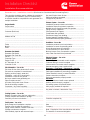
● User -
Name, Address, Contact Person,
Phone / Mobile Nos., Email
● Consultant - Name, Address, Contact Person,
Phone / Mobile Nos., Email
● Supplier Name, Address, Contact Person,
Phone / Mobile Nos., Email
● Service Provider - Name, Address, Contact Person,
Phone / Mobile Nos., Email
● Equipment major details:
● Engine number and make
● AC Generator number and make
● Equipment number and make
● Major specifications
● Major loads – kVA/ kW ratings, starting
type and normal loading sequence
● Language for instructions
Always keep in mind that the installations should comply
with State / Central Government and other applicable
statutory requirements.
About this manual
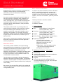
This manual provides installation and commissioning
general guidelines/recommendations for Cummins Diesel
Generating Set housed in an Acoustic Enclosure. In this
manual different types of installations (roof-top,
basement, room housed etc.) have been considered while
preparing the guidelines / recommendations. However,
any new, uncommon or critical installation needs to be
consulted with Cummins network.
B. Reference Literature / Information:
● Site drawing
● Installation and commissioning recommendations
plus Installation drawing
● Operation and Maintenance manual
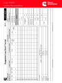
● Logbook
● Relevant approvals and certificates from the
concerned authorities like CPCB, SEB, Municipal
Corporation, Fuel Authority etc.
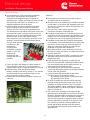
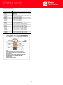
The information is supported by different photographs,
diagrams and reference information tables. The iformation
has been compiled together for adequate information but
still keeping in mind to make this manual crisp, handy and
user’s friendly.
We are sure, this manual will be useful to the installer and
in-turn to equipment user to achieve desired performance
of the generating set/s.
1