1
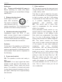
Owners Manual Excite X14A
Introduction
Introduction
Important safety instructions
The lightning flash with an arrowhead symbol within an equilateral
triangle, is intended to alert the user
to the presence of uninsulated “dangerous voltage” within the product’s
enclosure that may be of sufficient
magnitude to constitute a risk of
electric shock to persons.
The exclamation point within an
equilateral triangle is intended to
alert the user to the presence of important operating and maintenance
(servicing) instructions in the literature accompanying the product.
1.
2.
3.
4.
5.
6.
7.
Read these instructions.
Keep these instructions.
Heed all warnings.
Follow all instructions.
Do not use this apparatus near water.
Clean only with dry cloth.
Install in accordance with the manufacturer’s instructions.
8. Do not install near any heat sources such as radiators, heat registers,
stoves, or other apparatus (including
amplifiers)thatproduceheat.
9. Do not defeat the safety purpose of
the polarized or grounding-type plug.
A polarized plug has two blades with
one wider than the other. A grounding
type plug has two blades and a third
grounding prong. The wide blade or the
third prong are provided for your safety.Iftheprovidedplugdoesnotfitinto
Owner’s manual
your outlet, consult an electrician for replacement of the obsolete outlet.
10. Protect the power cord from being
walked on or pinched particularly at
plugs, convenience receptacles, and
the point where they exit from the apparatus.
11. Only use attachments/accessories specifiedbythemanufacturer.
12. Use only with the cart, stand, tripod, bracket, or table specified
by the manufacturer, or sold with the
apparatus. When a cart is used, use
caution when moving the cart/apparatus combination to avoid injury from tipover.
13. Unplug this apparatus during lightning
storms or when unused for long periods
of time.
14.Refer all servicing to qualified service
personnel. Servicing is required when
the apparatus has been damaged in
any way, such as power-supply cord
or plug is damaged, liquid has been
spilled or objects have fallen into the
apparatus, the apparatus has been
exposed to rain or moisture, does not
operate normally, or has been dropped.
Warning!
– To reduce the risk of fire or electrical
shock, do not expose this equipment to
dripping or splashing and ensure that
no objects filled with liquids, such as
vases, are placed on the equipment.
1
Introduction
– Be advised that different operating voltages require the use of different types
of line cord and attachment plugs.
– Always observe the local safety regulations. Ensure that the factory-set power
requirements for the device (refer to the
label on the back of the monitor) corresponds to the mains supply in your
region.
– This equipment should be installed
near the socket outlet and disconnection of the device should be easily accessible.
– To completely disconnect from AC
mains, disconnect the power supply
cord from the AC receptacle.
– The mains plug of the power supply
shall remain readily operable.
– Donotinstallinaconfinedspace.
– Do not open the unit – risk of electric
shock inside.
Caution:
You are cautioned that any change or modifications not expressly approved in this
manual could void your authority to operate
this equipment.
Service
– There are no user-serviceable parts inside.
– All service must be performed by qualifiedpersonnel.
2
EMC/EMI
This equipment has been tested and found
to comply with the limits for a Class B Digital device, pursuant to part 15 of the FCC
rules.
These limits are designed to provide reasonable protection against harmful interference in residential installations. This
equipment generates, uses and can radiate radio frequency energy and, if not installed and used in accordance with the instructions, may cause harmful interference
to radio communications. However, there is
no guarantee that interference will not occur in a particular installation. If the equipment does cause harmful interference to
radio or television reception, which can be
determined by turning the equipment off an
on, the user is encouraged to try to correct
the interference by one or more of the following measures.
– Reorient or relocate the receiving antenna.
– Increase the separation between the
equipment and receiver.
– Connect the equipment into an outlet
on a circuit different from that to which
the receiver is connected.
– Consult the dealer or an experienced
radio/TV technician for help.
For customers in Canada:
This Class B digital apparatus complies
with Canadian ICES-003.
Cet appareil numérique de la classe B est
conforme à la norme NMB-003 du Canada.
Introduction
Owner’s manual
3
Introduction
Introduction
Congratulations on your
your purchase
purchase of
of the
the
Dynaudio Excite X14A
X14A.active
With the
right care
monitor
and attention
it will
provide
many
years of
system.
With the
right
care and
attention
and many
trouble-free
audio
reproducitexcellent
will provide
years of
excellent
and
tion.
It is most
however,
that
trouble-free
audioimportant,
reproduction.
It is most
you
take ahowever,
few minutes
at this
stage
important,
that you
takeearly
a few
of
your speaker’s
life stage
to read
minutes
at this early
of this
yourmanual.
It
containslife
essential
to help
monitor’s
to readinformation
this manual.
It you
get
the best
from your
new speakers.
contains
essential
information
to help you
get the best from your new monitors.
The latest revision of this manual is always
available
our website:
The lateston
revision
of this manual is always
www.dynaudio.com
available on our website:
dynaudio.com
For support, please refer to:
www.dynaudio.com
For support, please refer to:
dynaudio.com/support/
Please enjoy!
Please enjoy!
4
Break-in time
The transducers
transducers of
of your
yourDynaudio
DynaudioExcite
Excite
X14A will achieve
achieve better
better sound
sound quality
quality after
breaking
in. Especially
after after
the first
after breaking
in. Especially
the hours
first
of
use,ofyou
may
notice
significant
advance
a
ant
hours
use,
you
may anotice
in
sound inquality,
further
advance
soundand
quality,
and subtle
furtherimprovements
in subsequent
of use.hours
subtle improvements
in hours
subsequent
of use.
Operation
Operation
Overview – rear panel
Correct setup and connections is essential
to achieve optimal performance from your
monitors. Please follow the instructions on
the following pages.
8
3
5
6
7
4
1
2
1.
2.
3.
4.
5.
6.
Power On/Off switch
AC power Input
Balanced analog input (XLR)
Unbalance analog input (RCA)
Power Mode switch
Remote
Owner’s manual
7. Filter switches
– High Pass
–LF–Lowfiltersetting
–MF–Midfiltersetting
–HF–Hifiltersetting
8. Level – Sensitivity switch
5
Operation
Setting up
1/2. Power on/off switch / AC power in
Before switching on, make sure Mains
Voltage matches your areas Mains Voltage
specification.
3. Balanced analog input
Audio Input is via a fe1:0
2
1
male XLR connector.
2:+
3
3:The input is electronically balanced with following connections. The connections are
printed on the rear for easy reference.
4. Unbalanced analog input (RCA)
Unbalanced Input via RCA. If your
audio source doesn’t have a balanced
output use the RCA input connection.
For best results always use only good quality screened cables and connectors.
Switches
Ontherearofthespeakeryouwillfindsix
switches for setting up the speaker for
optimum performance in different acoustic
environments. Each switch is explained in
the following.
5. Power mode switch
ON: The speaker is active and ready to
play.
ON/SLEEP: If no input signal has been
present on the input for 20 minutes, the
speaker enters “Sleep” mode and saves
power. The speaker is invoked and ready
to play when a signal is present on the input again. Wake-up time is approximately
two seconds.
6
7. Filter switches
LF: This switch controls the bass gain level
using shelf-type EQ. The level can be set to
+2 dB, 0 dB or -2 dB.
This filter is used to adjust for the proximity of boundaries, so if positioned close
to wall or corner, use the -2 dB setting.
If positioned far from walls use the +2 dB
or 0 position, depending on other
equipment,
and
personal
taste.
MF: This switch sets a notch filter,
used to compensate for the acoustic
effect of a console.
Such placement usually results in a response peak in lower midrange. The MF
switch activates a bell shaped notch
filter, which can compensate. Use either
the -2 or the -4 dB setting. Finding the
setting that providestheflattestresponse.
HF: This switch controls the Treble
level and it is used to match the high end
of the monitor to your other electronic
equipment,
and
your
acoustical
environment. Use the setting providing
the preferred timbre. If the sound is too
bright; try to set to -1 dB to reduce treble
by 1 dB. If the sound is too dull, use +1 dB
setting to raise the High Pass by 1 dB.
HP: This switch sets the lower cut-off
frequency of the speaker. It is used to
match the speaker to a subwoofer. You
can select between 60 Hz or 80 Hz Xover. Flat is used in case you do not
use a subwoofer
Operation
to assist your speakers. When used with
a subwoofer it is recommended to use
either 60Hzor80Hzfilter,thusallowinga
higherundistorted sound pressure level.
8. Level trim
Use this switch to match the sensitivity
of the Excite X14A to your source.
High-output Source: If your source has a
high output, set switch to the -10 position
to reduce sensitivity by 10 dB.
Low-output source: If your source has a
low output, set switch to the +4 position
to gain 4 dB more sensitivity.
Protection
The Excite X14A has several built in
protection systems to reduce the risk of
hazard or damage due to overloading.
Both power amplifiers have thermal
protection. This activates if a problem
should occur, and helps protect both the
electronics and the loudspeaker drivers.
The woofer channel has a built in
limiter that protects the woofer unit from
too much excursion. It works by reducing
the gain of the circuit when a certain
threshold level is reached.
Positioning
The Excite X14A is designed as
a precision speaker and can be
equally well used in both stereo and
surround setups. Optimal performance
is achieved when positioned 1 to 3 meters
from the listener.
Forbest results, the speakers should
be aimed towards the listener in both
vertical and horizontal planes.
Owner’s manual
7
Miscellaneous
Miscellaneous
Troubleshooting
If the Power LED lights green, but you hear
no sound, check your input signal, i.e. by
switching speakers.
Care
Components of the highest quality are used
in your Excite X14A. This assures years
of
trouble-free
operation.
Following
precautions should still be made though.
Avoid running the system into severe clipping. Although there is an advanced protection system, you may be able to destroy
your speakers by severe overpowering
them. The limiter works over a certain
range, but exceeding this level may send
a severely clipped signal to your drivers. When a noticeable distortion occurs,
please turn down the level to your speakers.
Avoid hot-plugging the equipment connected to the monitors. Always turn off the
speaker and other equipment when plugging or unplugging signals, or switching
equipment on or off.
Do not touch the drive units by hand. The
tweeter especially uses a very fine fabric
dome with an ultra-thin coating.
Options
Companion
subwoofers
for
the
Dynaudio Excite series are the Sub 250 II
and Sub 600 Precision Subwoofers.
Learn more about these subwoofers at:
www.dynaudio.com
8
Service
There are no user serviceable parts inside
the monitor. If service is required please
contact service via:
www.dynaudio.com
or
Dynaudio International GmbH
Ohepark 2
21224 Rosengarten
Germany
Tel: +49 4108 - 4180 - 0
[email protected]
Technicalspecifications
Technical specifications
Input level for 85 dB SPL @ 1 m, @ 0 dB setting,
unbalanced
80 mVrms
Max input level (@setting)
4,8 Vrms (-10 dB)
1,5 Vrms (0 dB)
1 Vrms (+4 dB)
Power consumption
Standby: 0.3 W
Idle: 5.8 W
Max: 94 W
Amplifierpower
Tweeter: 50 W
Max SPL 1 m, normal room, short term IEC signal
116 dB peak
Frequency Response (±3 dB)
45 Hz to 23 kHz
Resonance Frequency
56 Hz
Internal Cabinet Volume
6.9 liters
Bass Principle
Bassreflex
Weight
6.5 kg
Dimensions (Width x Depth x Height)
170 x 246/262 x 282 mm
Crossover
2 way
Crossover Frequencies
3000 Hz
Crossover Slope
12 dB/oct
Connection
XLR balanced and
Woofer: 50 W
RCA unbalanced
Recommended Placing
Stand
Tweeter
27mmsoftdome,rearchamber,magneticfluid 4 mm
aluminum front
Pure aluminum wire voice coil
Woofer
145 mm molded aluminum frame
One piece thermo formed MSP cone
38 mm voice coil with pure aluminum wire on aluminum
former.
Cabinet
Designed to be placed on a stand.
8 mm MDF
Crossover
Active, DSP based
Amplifier
Input sensitivity selector
HF, MF and LF trim selector
High pass frequency selector
Auto standby/On selector
Highefficiencydigitalpoweramplifiers.
Switch mode power supply with wide range input
Duetocontinuousdevelopment,thesespecificationsaresubjecttochangewithoutnotice.
Owner’s manual
9
© Dynaudio A/S, 8660 Skanderborg, Denmark, Owners Manual Excite X14A
All text and image copyrights reserved. Subject to change without notice. www.dynaudio.com