1
12:05 PM
Page 1
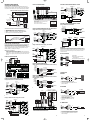
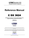
3. THREE WAYS TO CONTROL VOLUME USING THE VSE100
SENSE CONNECTIONS
If the SENSE feature is being used, the VSE100 will Mute when voltage is
absent but does not Un-Mute when voltage is present. The VSE100 will turn
on in a Muted state This allows the system or zone to be turned on without
the VSE100(s) playing audio. Stand-alone applications can simply use a
power supply plugged into to a switched outlet and connected to the SENSE
wire (Br/White) and Ground (Brown.) When connecting to an ELAN S6 or HD
system, either zone-specific or system-wide sensing is possible. ELAN Z
systems will provide system ON/OFF only.
STAND-ALONE
TO SWITCHED
OUTLET
Blue
Wh/Blue
Orange
Wh/Orange
Green
Wh/Green
Brown
Wh/Brown
TO
VSE100
+
TO S6 ZONE TRIGGER OUT
OR SYSTEM TRIGGER OUT
TIP=(+) RING=(-)
Override: Allows Page/Doorbell signals to override the music at a preset
# VSE100s
PER S6
# OF
ZPADS
HD
# VSE100s
PER Z630
# OF
ZPADS
# VSE100s
PER Z630
6
12
3
9
1
4
8
9
4
6
2
1
10
6
5
3
3
0
12
3
6
0
4
0
SPECIFICATIONS
ELAN Z
Blue
Wh/Blue
Orange
Wh/Orange
Green
Wh/Green
Brown
Wh/Brown
TO
VSE100
TO Z630 REMOTE OUT
TIP=(+) RING=(-)
ELAN HD
TO HDC2010 DUAL
ZONE CARD "RELAY" PORT
TIP=(+) RING=(-)
OR
TO HDC2000
SWITCHED
OUTLET
TO
VSE100
NOTE: HDC2010 Jumpers
must be set correctly
Blue
Wh/Blue
Orange
Wh/Orange
Green
Wh/Green
Brown
Wh/Brown
12VDC
1 AMP
REGULATED
POWER SUPPLY
-
+
NESS FOR A PARTICULAR PURPOSE.
WARNING TO OUR VALUED CUSTOMERS
1. Use the VOLUME UP/DOWN buttons to find a suitable level for the
Page and Doorbell Override signal.
2. Press and hold the MUTE button. While continuing to press the MUTE
button, press and hold the VOLUME UP button.
3. When the POWER SENSE LED starts to blink, the OVERRIDE level is set.
VSE100 REMOTE CONTROL
(MODEL EVCR)
ELAN
VOLUME
UP
VOLUME
DOWN
MUTE
ELAN HOME SYSTEMS, L.L.C. ("ELAN") warrants the VSE100 Electronic Stereo Volume
Control to be free from defects in materials and workmanship for two years (2 years)
from the date of purchase. If within the applicable warranty period above purchaser
discovers such item was not as warranted above and promptly notifies ELAN in writing,
ELAN shall repair or replace the items at the company's option. This warranty shall not
apply (a) to equipment not manufactured by ELAN,(b) to equipment found to have been
installed by other than an authorized ELAN installer, (C) to installed equipment which is
not installed to ELAN's specifications, (d) to equipment found to have been repaired or
altered by others than ELAN, (e) to equipment found to have been subject to negligence, accident, or damage by circumstances beyond ELAN's control, including, but
not limited to, lightning, flood, electrical surge, tornado, earthquake, or any other catastrophic events beyond ELAN's control, or to improper operation, maintenance or storage, or to other than normal use of service. With respect to equipment sold by, but not
manufactured by ELAN, the warranty obligations of ELAN shall in all respects conform
and be limited to the warranty actually extended to ELAN by its suppliers. The foregoing warranties do not cover reimbursement for labor, transportation, removal, installation, or other expenses which may be incurred in connection with repair or replacement. Except as may be provided and authorized in writing by ELAN, ELAN shall not be
subject to any other obligations or liabilities whatsoever with respect to equipment
manufactured by ELAN or services rendered by ELAN.
THE FOREGOING WARRANTIES ARE EXCLUSIVE AND IN LIEU OF ALL OTHER
EXPRESSED AND IMPLIED WARRANTIES EXCEPT WARRANTIES OF TITLE, INCLUDING BUT NOT LIMITED TO IMPLIED WARRANTIES OF MERCHANTABILITY AND FIT-
CONFIGURING OVERRIDE VOLUME LEVEL
VOLUME
LEVEL
LEDS (12)
Power Rating--Nominal................................. 100 Watts RMS per Channel
Frequency Response..................................... 20-20KHz +/- 0.5dB @ 8 Ohms
Total Harmonic Distortion.............................. < 1%
Imedance Settings......................................... Variable 1X/2X/4X
Minimum Speaker Load.................................4 Ohms
Dynamic Range.............................................. 49 dB (max to min audible)
Override Current Draw................................... 0.75 mA (Logic only)
Sense Current Draw....................................... 25 mA
Maximum Current Draw................................. 40 mA
Operating Voltage.......................................... 12 Volts DC
Sense Voltage.................................................9-12 Volts DC
Override Voltage.............................................9-12 Volts DC
Colors..................................................White, Ivory, Almond, Black, and Brown
WARRANTY
Blue
Wh/Blue
Orange
Wh/Orange
Green
Wh/Green
Brown
Wh/Brown
TO
VSE100
POWER/IR
ACTIVITY
LED
High-Power Capability: Handles up to 100 Watts RMS.
level even with volume turned all the way down or with the VSE100 in Mute.
# OF
ZPADS
Blue
Wh/Blue
Orange
Wh/Orange
Green
Wh/Green
Brown
Wh/Brown
ON
UN-MUTE
OFF
MUTE
To ensure that consumers obtain quality pre-sale and after sale support and service,
ELAN Home Systems™ products are sold exclusively through authorized dealers.
ELAN products are not sold online. The warranties on ELAN products are NOT VALID if
the products have been purchased from an unauthorized dealer or an online E-tailer.
To determine if your ELAN re-seller is authorized, please call ELAN Home Systems at
(859)269-7760.
ELAN HOME SYSTEMS
2428 Palumbo Dr. Lexington, KY 40509
Voice 859-269-7760
FAX 859-269-7972
ELAN Tech Support 859-269-7760 If on site: 800-622-3526
email: [email protected]
www.elanhomesystems.com
MUTE
ON/OFF
IR
RECEIVER
ELAN’s VSE100 is an electronic 12 step stereo Volume Control with Variable
Impedance Match settings of 1X, 2X, and 4X designed for use with amplifiers of up to 100 Watts output. The VSE100 features an IR receiver which
passes IR data to other sources as well as accepting IR information from
remote controls or other IR devices. The VSE100 also features an IR input
so that external controllers (ZPad® Keypads, VIA!® Color LCD Touchpanels,
etc.) can be hard wired to this device without using an IR emitter.
Additionally, the VSE100 features ELAN’s patented Page/Doorbell Override
to work with ELAN communication equipment. Impedance Match adjustments allow multiple pairs of speakers to be connected to the same amplifier channels without damaging the amplifier.
FEATURES
Z630
S6
ELAN S6
TO
VSE100
NOTE: The VSE100 will respond to any ELAN VOLUME UP/DOWN commands
found in the VIA!®TOOLS IR Library, EVCR remote, and
other ELAN remotes (Z030 and EVCR.) The EVCR remote
can be used to teach other learning remotes when necessary.
Remember, ELAN VOLUME UP/DOWN commands will control the
VSE100, but the VSE100 VOLUME UP/DOWN commands will NOT
control other ELAN equipment.
MAXIMUM NUMBER OF VSE100s PER
ELAN SYSTEM CONTROLLER
12VDC
1 AMP
REGULATED
POWER SUPPLY
-
a. Press VOLUME UP or VOLUME DOWN buttons on the VSE100.
b. Press VOLUME UP or VOLUME DOWN buttons on an ELAN remote
control.
c. Issue any ELAN VOLUME UP or VOLUME DOWN command.
INTRODUCTION
ELECTRONIC VOLUME
CONTROL REMOTE
© 2004 ELAN Home Systems
Lexington, KY USA
OPERATION
1. NINE WAYS TO TURN THE VSE100 ON (The VSE100 Volume level LEDs
are OFF.)
a. Press the MUTE button on the VSE100.
b. Press ON on the supplied remote.
c. Issue any ELAN Source Select IR command.
NOTE: When the VSE100 is turned ON using any of the above methods, the
Volume level is restored to the last setting before the VSE100 was
turned OFF.
d. Press the VOLUME UP button on the VSE100.
e. Press VOLUME UP on the supplied remote.
f. Issue any ELAN VOLUME UP IR command.
Impedance Matching: Allows multiple speaker pairs to be connected
to a single pair of amplifier channels.
IR In/Out: A built-in IR receiver allows the VSE100 to be controlled from,
universal remotes, keypads, VIA! Color LCD Touch Screen, or outboard IR
receiver. IR can be sent to the VSE100 using an IR emitter or through the
RJ45 jack on the rear of the unit. IR can be sent from the IR output to
source equipment, IR distribution networks or whole-house controllers.
SENSE: Detects absence or presence of voltage. When voltage is absent,
the VSE100 goes into Mute. The presence of voltage DOES NOT un-mute
the VSE100, however. A physical button press is required to un-Mute this
device. This allows the system or zone to be turned on without all of the
VSE100s in the system playing audio. Each VSE100 will turn on when the
Zone or System turns on, but they will all be in Mute. When connecting to
ELAN S or HD systems, the SENSE feature can be used for either zone-specific or system-wide detection. ELAN Z systems provide system On/Off
detection only.
ROUGH-IN
The VSE100 fits into most 18 cu. in. rough-in boxes and P-rings. P-rings
allow the best access and depth and should be used where local building
codes allow. DO NOT install the VSE100 in the same electrical box as highvoltage (110VAC) devices such as dimmers, light switches, etc. as these
devices will cause harmful interference and create buzzing, humming, or
other audio interference. Close proximity to high-voltage devices can also
cause undesired IR operation.
Like any IR device, the VSE100’s IR receiver is susceptible to interference
from ambient light, sunlight, or plasma television radiation. Please do not
mount the unit in locations susceptible to these conditions.
NOTE: The VSE100 is not warranted for outdoor installation.
WIRING
Speaker wire and CAT5 cable should be run from the main equipment location where the system’s amplifier is located to the mounting location for
each VSE100. The speaker terminals on this unit will accommodate 14 to 24
AWG stranded copper speaker wire. Runs that exceed 150 feet should use
heavier gauge wire, but 16 or 18 AWG is usually sufficient. Check local
building codes for specific guidelines regarding in-wall wire runs. CAT5
cable is required when installing this unit to provide Power, Override, Sense,
IR In, and IR Out. This unit must be connected to power in order to function.
RJ45 CONNECTIONS
1. Use ELAN C45P pre-terminated RJ45 cables or crimp your own
using the ELAN standard color code and pin-out.
2. Consult the following diagrams for specific CAT5 wiring requirements
for stand-alone or ELAN system operation.
3. Once proper connections are made at the head-end, plug the RJ45
connector into the jack on the rear of the VSE100.
4. Install the unit in the wall using the provided screws. Be careful not to
place tension on the CAT5 cable.
5. Test and adjust.
STANDARD ELAN RJ45 PINOUT
www.elanhomesystems.com
2428 Palumbo Dr
Lexington, KY 40509
P/N 9900515 REV: B
NOTE: When the VSE100 is turned ON using any of the above methods, the
Volume level is restored to the last setting before the VSE100 was
OFF but no higher than the OVERRIDE Volume level setting.
g. Press the VOLUME DOWN button on the VSE100
h. Press VOLUME DOWN on the supplied remote.
i. Issue any ELAN VOLUME DOWN command.
1
2
3
4
5
6
7
8
TAB
VSE100 PIN ASSIGNMENT
Blue
Blue/Wh
Orange
Orange/Wh
Green
Green/Wh
Brown
Brown/Wh
2. THREE WAYS TO TURN THE VSE100 OFF (The VSE100 Volume level
LEDs are ON.)
a. Press the MUTE button on the VSE100.
b. Press OFF button on the supplied remote.
c. Issue any ELAN SYSTEM OFF command.
5
Override
IR Out
IR In
N/C
N/C
+12VDC
Ground
Sense
SPEAKER CONNECTIONS
1. Verify that the amplifier is powered down. Do not connect the RJ45
conector of the VSE100 at this point.
2. Strip back 1/4” of the insulation from each conductor of the speaker
wire. Twist and verifythat there are no frayed ends.
3. Remove the AMPLIFIER and SPEAKER connectors from the volume
control. Connect the L+, L-, R+, R- conductors from the amplifier to
the appropriate terminal on the AMPLIFIER connector. Make sure to
maintain proper +/- polarity!
4. Connect the wires from the speakers to the appropriate terminals on
the SPEAKER connetor, again ensuring proper +/- polarity.
5. Replace the AMPLIFIER and SPEAKER connectors.
AMPLIFIER
L+ L- R- R+
RJ45
NOTE: When the VSE100 is turned ON using any of the above methods, the
Volume level is set to the lowest audible level.
Blue
Wh/Blue
Orange
Wh/Orange
Green
Wh/Green
Brown
Wh/Brown
CABLE
SPEAKER
L+ L- R- R+
7/12/2004
FRONT
VSE100Manual.qxd
TO SPEAKERS
CAT-5
FROM AMPLIFIER
SERIES
VSE100
HIGH POWER ELECTRONIC
STEREO VOLUME CONTROL
W/ OVERRIDE and IR
DO NOT REVERSE AMPLIFIER AND SPEAKER CONNECTIONS!!
1
VSE100Manual.qxd
7/12/2004
12:06 PM
Page 2
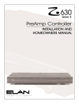
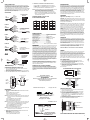
ELAN Z SYSTEM DIAGRAM
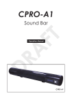
DESIGN/CONFIGURATION
STAND-ALONE CONFIGURATION
ZONE 1 (FIXED)
The VSE100 can be used in stand-alone configuations without using an
ELAN whole-house controller. Each stand-alone scenario will be slightly different, but all will connect the same way as the following diagram explains.
CAT-5
A/V RECEIVER
IR EMITTER
LEFT
SPK
MUTE
Blue
Wh/Blue
Orange
Wh/Orange
Green
Wh/Green
Brown
Wh/Brown
HDC2010
IR INPUT
ZONE 3
ZONE 1
VSE100 STAND-ALONE APPLICATION
R
L
R
L
TBK2000U
Punchdown Block
ZONE 3 (FIXED)
ZONE 2 (VARIABLE)
R
L
ELAN HD SYSTEM CONNECTIONS W/ VSE100
CAT-5
MUTE
Blue (Status)
White/Blue
ZPAD
Blue (Override)
Z660
ZONE 2
VSE100
TO HDC2042
AUTOMATION
CARD
RELAY
COMMON
RELAY
N/O
RIGHT
SPK
BROWN (GND)
L
WH/GREEN (+12V)
CHASSIS CONFIG.
+ -
CHASSIS CONFIG.
MUTE
BROWN (GND)
3 ZONE Z SYSTEM
ZONE 1 CONTROLLED W/ ZPAD THROUGH VSE100
ZONE 2 CONTROLLED W/ ZPAD
ZONE 3 CONTROLLED W/ VSE100 & IR REMOTE
ZONE 3 VAR / FIX
12VDC
1 AMP
+
+
-
Z630
CAT-5
ZONE 1 VAR / FIX
12VDC REGULATED
POWER SUPPLY
R
ZONE 2 VAR / FIX
WH/BLUE (IR)
1
2
3
4
5
+
USE REGULATED 12VDC
POWER SUPPLY (12VDC/1 AMP)
12VDC
1 AMP
ELAN HD SYSTEM CONNECTIONS W/ VSE100
Using A PHD12 Precision Panel
ON
Z630 DIP SWITCH SETTINGS
PHD12 ZONE
CONNECTOR
The basic connections for stand-alone systems are as follows:
1.
2
3.
4.
Amplifier Input: Speaker wires from the amplifier (L+/-, R+/-)
Speaker Output: Speaker wires to speakers (L+/-, R+/-)
Power: +12 Volts DC & Ground (RJ45 +12VDC=Gr/Wh,GND=Br)
IR: IR Output and Ground (RJ45 IR=Wh/Bl, GND=Br)
STAND-ALONE PINOUT
TBK2000U
Punchdown Block
PIN6 WH/GREEN (+12VDC)
+
NOTE: Zones vs. Sub-Zones
A “Zone” is defined as an area of a whole-house audio system that has
separate source control/selection capabilities.
A “Sub-Zone” is a room or area that shares source selection/control with
another area, but typically has separate ability to control volume for the
sub-zone.
R
L
CAT-5
USE 12VDC
REGULATED
POWER SUPPLY
(12VDC/1 AMP)
VCO RELAY +12V
CONNECTOR
RELAY
CONNECTOR
1
2
3
4
5
6
7
8
R1 N.O.
1
R1 COM
R2 N.O.
2
R2 COM
3
R3 N.O.
4
R4 N.O.
R3 COM
R4 COM
VCO #1 CONNECTIONS SHOWN
IR INPUT
ZPAD
Blue (Override)
VSE100
The VSE100 has an IR Output (utilizing the built-in IR receiver) and an IR
Input (to control the VSE100 from another device.) When designing systems
with sub-zones, this IR Input will allow individual sub-zone control (including
Volume) from a keypad without having to use a separate Volume Control
mounted in the wall.
IR INPUT DIAGRAM
Blue (Override)
VSE100
ZPAD
1 ZONE SHOWN
ZPADS CONTROL SUB-ZONE VOLUME
THROUGH VSE100s
EACH SUB-ZONE HAS SEPARATE CONTROL
CAT5
+
Blue (Override)
MUTE
VSE100
-
VSE100s
USE REGULATED 12VDC
POWER SUPPLY (12VDC/1AMP)
MUTE
+
+
+
+
TO VSE100
Blue
Wh/Blue
Orange
Wh/Orange
Green
Wh/Green
Brown
Wh/Brown
12VDC
1 AMP
VSE100
Brown (Gnd)
Blue (Override)
Blue
Wh/Blue
Orange
Wh/Orange
Green
Wh/Green
Brown
Wh/Brown
ELAN S6 SYSTEM DIAGRAM
+
Blue
Wh/Blue
Orange
Wh/Orange
Green
Wh/Green
Brown
Wh/Brown
TBK2000U
Punchdown Block
Z600
CONTROL
OUTPUT
ZPAD
VSE100
ELAN Z SYSTEM CONNECTIONS W/ Z600 AND VSE100
Using an External Power Supply for Override
Z630 IR
INPUT
Blue (Status)
VCO
CONNECTOR
TO Z600
CONTROL
OUTPUT
12VDC
1 AMP
IR (Wh/Blue)
Status (Blue)
+12V (Wh/Green)
Gnd (Brown)
IR (Wh/Blue)
Status (Blue)
+12V (Wh/Green)
Gnd (Brown)
ZPAD
Blue (Override)
The VSE100 is ideally suited for many ELAN whole-house audio distribution
applications. Features such as Volume Control Override, Impedance
Matching, SENSE, and the built-in IR receiver allow this unit to seamlessly
integrate into the most basic or complex ELAN systems that the installer can
imagine. Following are diagrams showing typical applications using the
VSE100 in ELAN S, Z, and HD system designs.
-
White/Blue
IR EMITTER
ELAN SYSTEM CONFIGURATIONS
+ -
Blue
Wh/Blue
Orange
Wh/Orange
Green
Wh/Green
Brown
Wh/Brown
TO Z630
IR INPUT
PIN2 WH/BLUE (IR)
PIN7 BROWN (GND)
ELAN Z SYSTEM CONNECTIONS W/ Z600 AND VSE100
Using Internal Power of Z600 for Override
CAT5
ELAN PREAMP
ZPAD
CAT5
ELAN Z SYSTEM CONNECTIONS
Using a PZ6 Precision Panel (VSE100 Located in Zone)
MUTE
PZ6 ZONE
CONNECTOR
Wh/Brown
Brown
Wh/Green
Green
Wh/Orange
N/C
Wh/Blue
Blue
CAT-5
Ground (Brown)
+12V (Wh/Green)
RS485- (Green)
RS485+ (Wh/Orange)
IR (Wh/Blue)
Ground (Brown)
+12V (Wh/Green)
IR (Wh/Blue)
Override + (Blue)
R
L
ZPAD
VSE100
CONNECTIONS
w/ZPAD
ELAN Z SYSTEM CONNECTIONS
Using a PZ6 Precision Panel (VSE100 Located at HeadEnd Controlled w/ ZPAD)
ELAN S6 SYSTEM CONNECTIONS W/ Z600 AND VSE100
Using Internal Power of Z600 for Override
TBK2000U
Punchdown Block
S6 ZONE
KEYPAD
INPUT
S6 PAGE
TRIG IN
Blue
Wh/Blue
Orange
Wh/Orange
Green
Wh/Green
Brown
Wh/Brown
Blue (Override)
TIP Blue
TIP SLEEVE
Wh/Brown
Brown
Wh/Green
Green
Wh/Orange
N/C
Wh/Blue
Blue
Ground (Brown)
+12V (Wh/Green)
RS485- (Green)
RS485+ (Wh/Orange)
HDC2010
R
S6 PAGE
TRIG IN
SENSE
A
RELAY
A
SENSE
B
RELAY
B
ZONE
B
L
R
SLEEVE
Z600
CONTROL
OUTPUT
12VDC
1 AMP
R
A
MUTE
R
B
+
-
Blue (Override)
Blue (Override)
Solid
+12VDC
Ground
Stripe
Center
IR TUBE
Connect IR Input (Orange) of VSE100 to
Solid (non-center) wire of IR Tube.
Connect 12VDC (Wh/Green) of VSE100
to Striped wire of IR Tube.
Connect Ground (Brown) to center wire
of IR Tube.
FIXED
TO
VSE100
VSE100
HD SYSTEM 1 ZONE SHOWN
VARIABLE SPEAKERS CONTROLLED W/ ZPAD
FIXED SPEAKERS CONTROLLED W/ VSE100
USE REGULATED 12VDC
POWER SUPPLY (12VDC/1 AMP)
2
IR
w/ MINI-PLUG
VSE100
VSE100
Blue
Wh/Blue
Orange
Wh/Orange
Green
Wh/Green
Brown
Wh/Brown
VAR
Z660
Blue
Wh/Blue
Orange
Wh/Orange
Green
Wh/Green
Brown
Wh/Brown
ZPAD
FIXED
TIP Blue
TIP
VAR
ZPAD
Blue (Override)
SERIAL
PORT
L
SLEEVE Green
HDC2042
RELAY
OUTPUTS
L
ZPAD
Brown
Connect IR Output (Orange) from ZPAD
to IR Input (Orange) of VSE100.
Connect Ground (Brown) from ZPAD to Ground
(Brown) of VSE100.
TO
VSE100
ZONE
A
VARIABLE
TBK2000U
Punchdown Block
Orange
w/IR TUBE
VOLUME CONTROL OVERRIDE
L
Blue
Wh/Blue
Orange
IR IN
Wh/Orange
Green
Wh/Green
Brown Ground
Wh/Brown
VSE100
ELAN HD SYSTEM DIAGRAM
FIXED
Blue
Wh/Blue
Orange
Wh/Orange
Green
Wh/Green
Brown
Wh/Brown
Ground (Brown)
+12V (Wh/Green)
IR IN (Orange)
IR OUT (Wh/Blue)
Override + (Blue)
ELAN S6 SYSTEM CONNECTIONS W/ Z600 AND VSE100
Using an External Power Supply for Override
S6 ZONE
KEYPAD
INPUT
ZPAD
IR (Orange)
VSE100
Blue
Wh/Blue
Orange
Wh/Orange
Green
Wh/Green
Brown
Wh/Brown
Z600
CONTROL
OUTPUT
PZ6 ZONE
CONNECTOR
ZPAD
SLEEVE Green
TO
VSE100
3
Blue
Wh/Blue
Orange
Wh/Orange
Green
Wh/Green
Brown
Wh/Brown
IR
Ground
TIP +
RING -
Connect IR Input (Orange) of VSE100 to IR Output
of device sending IR (ELAN pre-amp, for example.)
Connect Ground (Brown) of VSE100 to Ground of
device sending IR.
4