1
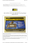
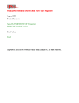
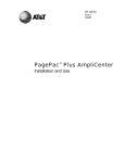
Product Review & Short Takes Columns from QST Magazine
October 2001
Product Reviews
Ten-Tec Model 526 6N2 Multimode VHF Transceiver
Ranger Communications RCI-2970DX 10/12-Meter Transceiver
Short Takes
SignaLink SL-1 Sound Card/Transceiver Interface
Copyright © 2001 by the American Radio Relay League Inc. All rights reserved.
PRODUCT REVIEW
Ten-Tec Model 526 6N2 Multimode VHF Transceiver
Reviewed by Brennan Price, N4QX
Field and Regulatory Correspondent
Like most hams who earned their licenses within the past few years, I began
my ham operating adventures on the
2-meter band. My first two rigs were
single-band FM-only handheld and
mobile transceivers. I had learned about
the magic of VHF weak-signal operation
while studying for my first license. I
somewhat naively believed that new allmode gear would be abundant and inexpensive. As it turned out, my first two FM
rigs combined were far less expensive than
any new all-mode VHF transceiver I could
find. I did have fun on the weak-signal
modes, but only through the facilities of
Georgia Tech’s club station, W4AQL.
As I upgraded, HF caught my fancy,
and from that point forward any of my
savings earmarked for station improvements were appropriated away from my
VHF roots. Still, the availability of a VHF
all-mode rig for the budget-conscious
beginner would have been appealing.
When I witnessed the unveiling of
Ten-Tec’s Model 526—or “6N2”—at the
Dayton Hamvention, I immediately recalled those halcyon days of my Amateur
Radio youth. I thought to myself, “Self,
had this been available in 1997, this may
very well have been your first rig.” The
6N2 delivers not just one, but two of the
most popular weak-signal VHF bands, 6
and 2 meters (thus the nickname of the
rig). It supports CW, SSB and FM operation. And priced at just under $700, it’s
not terribly cost prohibitive to the thrifty
ham, who might spend nearly as much on
a high end FM-only VHF/UHF mobile
transceiver. Weak-signal enthusiasts will
confirm that having access to these modes
on these particular bands can be very
worthwhile. Don’t take our word for it
though—check out Emil Pocock’s “The
World Above 50 MHz” column that appears each month in QST.
How would this rig hold up under fire?
I anxiously volunteered to find out.
Operating Conditions
A full understanding of my experiences with the 6N2 requires an appreciation of my QTH. Affectionately known
as the “N4QX Microstation of Power,”
my station is not in an environment where
any rig easily shines. I live on the second
floor of a three-story apartment building,
facing a parking lot, with no readily available support structures for antennas other
than simple dipoles. Most serious VHF
operators use beams, but beams are out
of the question for me. If I could put the
6N2 to enjoyable use under these conditions, surely it could be put to even better service from a more ham hospitable
location—fixed or portable.
Upon opening the box, I was struck by
the similarity in size and weight to TenTec’s Scout—my current HF transceiver.
It even resembles the Scout to some extent, with the green LED display and
prominent tuning knob. I had just finished
operating Field Day as a solo operator,
where the Scout was my weapon of
choice. Both rigs are appealing for portable applications due to their small size
and light weight, and I made a mental note
to seriously consider supplementing my
setup with a couple of more bands next
June.
Getting on a Repeater—the Ford
Test
I am a firm believer in the Steve Ford,
Bottom Line
The Ten-Tec Model 526 delivers
multimode fun on the two most popular VHF bands—6 and 2 meters. Use
it to chat with the locals on the FM
repeaters, or expand your radio
horizons with an exploration of the
wonders of the weak-signal modes.
Joe Bottiglieri, AA1GW
From October 2001 QST © ARRL
WB8IMY, test of VHF FM rigs. This test
involves taking the rig out of the box,
tossing the instruction manual off toward
the other side of the room, and seeing
how quickly one can raise a local repeater
relying on instinct alone. After hanging
a trusty Zack Lau, W1VT, 2-meter
ground-plane antenna on a hook outside
my windowsill (see “Build a Portable
Groundplane Antenna,” QST, Jul 1991),
I set my sights on raising the nearby
W1AW repeater.
Connecting the power supply and the
antenna was simple enough; the 6N2
sports a two-pin power connector and
separate SO-239 connectors for 6- and
2-meter antennas. A four-pin microphone
connects to the front panel. (Ten-Tec’s
basic handheld microphone—the Model
701—is included.) The AF knob, clearly
labeled and conveniently located at the
bottom right of the front panel, doubles
as the power switch and turns the radio
on or off with a satisfying audible click.
The MODE and BAND buttons are located
just above. The available modes—CW,
USB, LSB and FM—are selected by
pressing the MODE button. Translucent
icons situated along the top of the display window light to indicate the active
mode. Additional icons on either side of
these show the state of several other operating parameters. These include VFOA,
VFOB, MEM, SPLIT, TONE and RIT . The
tuning knob is impossible to miss; dialing in 145.45 MHz was not a problem.
This is where I hit a snag. It was not
immediately apparent to me how to enter
the repeater offset. This is clearly ex-
Assistant Technical Editor
plained in the manual—and below—but
the procedures for the Ford test dictate
perseverance before I resorted to retrieving the manual from somewhere behind
the couch. I noticed the A/B and SPLIT
buttons to the right of the tuning knob.
Ah, dual VFOs! I had my solution. I tuned
144.85 MHz into the second VFO and
returned the first VFO to the display (only
one frequency is shown at a time). A press
of the SPLIT button lit the corresponding
icon atop the display.
I turned up the MIC gain and PWR controls on the lower left front panel and
keyed the microphone—the display
flipped to 144.85. After announcing
“N4QX monitoring,” I unkeyed and savored the sweet synthesized sounds of
success: “This is the W1AW repeater
[beep].” The 6N2 had passed the Ford
test, going from in the box to on the air
in just under six minutes. All without the
benefit of the manual—and without ever
knowing the proper procedure for setting
up a repeater split!
It turns out that the correct way to set
a standard repeater split is through the use
of the RIT button. In the narrowband
modes—CW and SSB—receive incremental tuning operates just as it does on
any HF rig. The 6N2’s RIT can be adjusted anywhere within ±10 kHz of the
transmit frequency. The offset amount
appears on a sub display to the right of
the main frequency display, and is controlled with an unlabeled knob to the left
of the concentric AF/SQL knobs. This unlabeled knob does different things in different situations. The manual calls it
“multi” (it would have been nice had it
been similarly labeled on the rig).
While in the FM mode, pressing this
same button will cause the frequency offset value to appear in the supplemental
display. The multi knob then allows
selection of specific offsets: –600 kHz,
0 kHz and +600 kHz on 2 meters, and
–1 MHz, −500 kHz, 0 kHz, 500 kHz, and
1 MHz on 6 meters. Users in areas where
nonstandard splits are employed (1 MHz
and 1.035 MHz on 2 meters, or 240 kHz
on 6 for example), fret not. These odd
splits are accommodated by using the two
VFOs and the split function—precisely
the method I had stumbled upon during
the Ford test.
CTCSS encoding is enabled by using
the TONE subfunction of the B/W (bandwidth) button. Subfunctions are assigned
to five of the radio’s buttons and are accessed by first pressing the FUNCtion button, positioned to the lower right of the
tuning knob. The transmitted tone’s value
is adjusted by—you guessed it—the multi
knob. Forty-two tones are available.
The 6N2 can only send a CTCSS tone;
it cannot decode an incoming tone (sometimes referred to as “tone squelch”).
CTCSS decode tends to come in really
handy in densely populated environments, and an increasing number of repeaters are superimposing these subaudible tones on their output frequencies.
The memory functions and programming are no more complicated than they
are on any other radio. Once you’ve set
the desired frequency—and any offset or
tone information—in the VFO mode, a
press of the MW (memory write) button
brings up a memory channel number
(from 00 through 99) in the supplemental display. The user turns the multi knob
to the desired memory position and
presses MW again to store. Pressing FUNC
before MW erases a memory.
When in memory mode, the user can
scan the programmed frequencies, and
there’s a “skip” feature for locking out
perpetually busy channels—NOAA
Weather Radio for example. There are
also provisions for scanning all frequencies between user-programmable limits.
Those who like to use scanning features
will not be disappointed.
Beyond FM—The Weak-Signal
Modes
The real fun of the 6N2 comes when
one toggles the mode from FM to CW or
SSB. With the press (or presses) of a button, an adequate FM rig becomes a very
capable and enjoyable weak-signal rig.
As soon as I got done playing with the
6N2 on the W1AW machine, I set my
sights on raising some attention on the
2-meter SSB calling frequency: 144.200
MHz. Despite the obvious limitations of
my small vertical antenna, N1OPO soon
answered from 6 miles away and gave
positive signal quality reports.
For those who have yet to experience
it, single sideband operation is very much
like FM—simply press the PTT switch
and talk. When switching over from the
FM mode, you’ll initially want to turn the
squelch all the way counterclockwise so
you’ll hear any weak signals down in the
noise.
A phono jack on the rear apron serves
as the connection point for a CW key. The
same switching line is used for push-totalk on SSB and FM; indeed, CW can be
sent by pressing the PTT switch on the
microphone. The CW offset and sidetone
pitch is adjustable in 20-Hz increments
from 400 to 1000 Hz, and these settings
“track” each other. CW operation is full
break in, and the 6N2 upholds Ten-Tec’s
reputation for silky smooth QSK.
The built-in DSP bandwidth filter, the
noise blanker and 20-dB attenuator are
nice features. Single sideband bandwidth
is adjustable (once again, through the
multi knob) from 1500 to 2800 Hz, and
the CW bandwidth can be further adjusted down to 200 Hz. The DSP-based
filter arrangement is very flexible and
quite effective. The attenuator is nice for
those rare receiver overload situations,
but there is no indicator on the display
when it is turned on; users have to listen
for a marked increase or decrease in audio in order to determine the state of this
setting. The 10-step adjustable noise
blanker suppresses pulse-type noise, a
routine occurrence at my QTH. These
sporadic noise bursts were neatly eliminated with a press of the NB button, and I
was impressed.
Bells and Whistles—Amplifier
Control, Transverters, Digital Modes
and “Perfect Paul”
The 6N2 provides up to 20 W of RF
output power out of the box. Two separate phono connections for amplifier keying, one for each band, are located on the
rear panel. There are also rear-panel audio input and output jacks for connecting external devices such as TNCs or
computer sound cards. QRO and digital
operators should have no problem whatsoever figuring out what gets connected
where, and the phono-type jacks simplify
the task of making up cabling.
There is also a transverter switch
on the rear of the rig, which reroutes the
144-MHz output signal from the SO-239
output to a phono jack labeled XVTR OUT.
This jack delivers a low-level (+5 dBm)
2-meter transmit signal for driving
transverters. The receive signal from the
transverter is connected to the 6N2’s
2-meter SO-239 jack, and the transverter
is TR switched by the same connection
that would be used to key a 2-meter amplifier. Conveniently, activation of the
transverter feature does not affect 6-meter
operation. Unfortunately—unlike some
recently released transceivers—there are
no provisions for reprogramming the
6N2’s display to directly indicate the
“transverted to” frequency.
Many FM rigs include extended receive capability on the public safety,
MARS, CAP and business bands from
136-174 MHz. The 6N2 is no exception.
The farther the frequency is from 144148 MHz, however, the more cranking
that’s required to get there. Turning the
tuning knob is the only means of changing the frequency within a band while in
VFO mode. Although the “fast” tuning
setting for the FM mode allows tuning in
10-kHz steps, that’s still a lot of turns to
take us from 147 to, say, 162.55 MHz, a
popular NOAA frequency. Fans of
NOAA’s “Perfect Paul” should dial their
From October 2001 QST © ARRL
Table 1
Ten-Tec 6N2, serial number 04C10421
Manufacturer’s Claimed Specifications
Measured in the ARRL Lab
Frequency coverage: Receive, 50-54, 136-174 MHz;
transmit, 50-54, 144-148 MHz.
Receive and transmit, as specified
Power requirement: Receive, 0.4 A; transmit, 6 A.
Receive, 1.4 A (maximum volume); transmit, 4.4 A. Tested at 13.8 V.
Modes of operation: SSB, CW, FM.
As specified.
Size (HWD): 2.8×8.5×8.8 inches; weight, 4.5 pounds.
Receiver
Receiver Dynamic Testing
SSB/CW sensitivity, 2.4-kHz bandwidth, 10 dB S+N/N: 0.2 µV.
Noise floor (MDS), 500-Hz bandwidth:
50 MHz
–135 dBm1
144 MHz
–135 dBm1
FM sensitivity: Not specified.
For 12 dB SINAD:
52 MHz
0.72 µV
146 MHz
0.46 µV
Blocking dynamic range: Not specified.
Blocking dynamic range, 500-Hz filter:
spacing
20 kHz
5 kHz
50 MHz
125 dB*
68 dB
67 dB
144 MHz
112 dB*1
Two-tone, third-order IMD dynamic range: Not specified.
Two-tone, third-order IMD dynamic range, 500-Hz filter:
spacing
20 kHz
5 kHz
62 dB
50 MHz
77 dB1
144 MHz
88 dB1
66 dB
Third-order intercept: Not specified.
50 MHz2
144 MHz2
FM adjacent channel rejection: Not specified.
20-kHz channel spacing: 52 MHz, 61 dB; 146 MHz, 66 dB.
FM two-tone, third-order IMD dynamic range: Not specified.
20-kHz channel spacing: 52 MHz, 63 dB*; 146 MHz, 67 dB*;
10-MHz channel spacing, 52 MHz, 100 dB; 146 MHz, 98 dB.
–16 dBm1
–1.6 dBm
–54 dBm
–53 dBm
S-meter sensitivity: 50 µV at S9.
S9 signal at 50 MHz: 61 µV; 144 MHz, 67 µV.
Squelch sensitivity: Not specified.
At threshold: SSB, 50 MHz, 1.0 µV; FM,
52 MHz, 1.4 µV; 146 MHz, 1.2 µV.
Receiver audio output: Not specified.
2.0 W at 10% THD into 8 Ω.
IF/audio response: Not specified.
Range at –6 dB points, (bandwidth):
CW-N (500-Hz bandwidth): 385-1000 Hz (615 Hz);
CW-W: 154-2632 Hz (2478 Hz);
USB-W: 143-2632 Hz (2489 Hz);
LSB-W: 167-2667 Hz (2500 Hz).
Spurious and image rejection: Not specified.
First IF rejection, 50 MHz, 33 dB; 144 MHz, 75 dB;
image rejection, 50 MHz, 75 dB; 144 MHz, 89 dB.
Transmitter
Transmitter Dynamic Testing
Power output: SSB, CW, FM, 20 W (high); 1 W (low).
Typically 19 W high, <1 W low.
Spurious-signal and harmonic suppression: Not specified.
61 dB. Meets FCC requirements for spectral purity.
SSB carrier suppression: Not specified.
60 dB.
Undesired sideband suppression: Not specified.
57 dB.
Third-order intermodulation distortion (IMD)
products: Not specified.
See Figures 1 and 2.
CW keying characteristics: Not specified.
See Figure 3.
Transmit-receive turn-around time (PTT release to
50% audio output): Not specified.
S9 signal, 30 ms.
Receive-transmit turn-around time (tx delay): Not specified.
SSB, 10 ms; FM, 7 ms. Unit is suitable for use on AMTOR.
Composite transmitted noise: Not specified.
See Figure 4 and 5.
Note: Unless otherwise noted, all dynamic range measurements are taken at the ARRL Lab standard spacing of 20 kHz.
*Measurement was noise-limited at the value indicated.
1See text.
2Third-order intercept points were determined using S5 reference.
From October 2001 QST © ARRL
0
0
Reference Level: 0 dB PEP
Reference Level: 0 dB PEP
–10
–10
–20
–20
–30
–30
–40
–40
–50
–50
–60
–60
–70
–70
–80
–10
–8
–6
–4
–2
0
2
4
Frequency Offset (kHz)
6
8
10
Figure 1—Spectral display of the 6N2
transmitter during two-tone intermodulation distortion (IMD) testing on
6 meters. The worst-case third-order
product is approximately 32 dB below
PEP output, and the worst-case fifthorder product is down approximately
40 dB. The transceiver was being
operated at 20 W PEP output at 50.2 MHz.
local weather frequency in once, put it in
memory, and be done with it; otherwise,
they will spend a lot of time spinning the
big knob.
The fast tuning rate in CW and SSB is
an even more miserly 1 kHz. Temporarily
switching to the FM mode when making
significant frequency excursions in these
modes helps, but a wider selection of available tuning speeds—actually “steps” in
this case—would have been helpful. The
memories are “tuneable,” though.
Overall Impressions
I had a good time using this rig, both
on FM and the weak-signal modes. Its
shortcomings as an FM rig—primarily its
inability to decode CTCSS tones and lack
of DTMF capabilities for phone patch or
remote control—are far from fatal. Its
weak-signal capabilities are impressive
for a radio in this price class.
A close look at the Lab data in Table
1 reveals an overall level of performance
that compares favorably—and in some
instances surpasses—the SSB and CW
2- and 6-meter performance of the current crop of multiband HF/VHF/UHF
subcompact transceivers.
When we shared our initial Lab data
with the folks at Ten-Tec, the 6-meter
third-order intercept point (−16 dBm)
immediately caught their attention. This
measurement came in considerably lower
than their design objective. They requested that we return our radio for further investigation.
They traced the cause to a couple of
surface mount inductors on the RF board.
Axial-lead inductors were substituted.
Our subsequent Lab tests showed significant improvement. The 20-kHz offset
–80
–10
–8
–6
–4
–2
0
2
4
Frequency Offset (kHz)
6
8
10
Figure 2—Spectral display of the 6N2
transmitter during two-tone intermodulation distortion (IMD) testing on
2 meters. The worst-case third-order
product is approximately 27 dB below
PEP output, and the worst-case fifth-order
product is down approximately 40 dB.
The transceiver was being operated at
20 W PEP output at 144.2 MHz.
–60
–60
–70
Figure 3—CW keying waveform for the
6N2 showing the first two dits using
external keying. Equivalent keying speed
is 60 WPM. The upper trace is the actual
key closure; the lower trace is the RF
envelope. The transceiver was being
operated at 20 W output at 144.02 MHz.
Reference Level: - 60 dBc/Hz
Vertical Scale: dBc/Hz
–70
–80
–80
–90
–90
–100
–100
–110
–110
–120
–120
–130
–130
–140
2
4
6
8
10
12
14
16
18
20
Frequency Sweep: 2 to 22 kHz from Carrier
22
–140
2
Reference Level: - 60 dBc/Hz
Vertical Scale: dBc/Hz
4
6
8
10
12
14
16
18
20
Frequency Sweep: 2 to 22 kHz from Carrier
22
Figure 4—Spectral display of the 6N2
transmitter output during compositenoise testing at 50.02 MHz. Power output
is 20 W. The carrier, off the left edge of the
plot, is not shown. This plot shows
composite transmitted noise 2 to 22 kHz
from the carrier.
Figure 5—Spectral display of the 6N2
transmitter output during compositenoise testing at 144.02 MHz. Power output
is 20 W. The carrier, off the left edge of the
plot, is not shown. This plot shows
composite transmitted noise 2 to 22 kHz
from the carrier.
6-meter two-tone third-order dynamic
range increased by 11 dB (to 88 dB), and
the 2-meter measurement rose 2 dB (to
90 dB). Blocking dynamic range on 2 increased by 2 dB as well, up from 112 to
114 dB. SSB/CW sensitivity on 6 and
2 also gained a couple of dB. The improvements in 6-meter sensitivity and
two-tone third-order dynamic range
boosted the 6-meter intercept point up to
a reasonably respectable −4 dBm. The
6-meter blocking dynamic range, though
noise-limited, came in at a very impressive 125 dB (both pre and post modification)!
Ten-Tec reports that the component
changes have been implemented in all
current production units, and are offering an update kit to purchasers of earlier
units. Contact them directly for details.
The casual operator will find that this
rig will do nearly everything one could
ever want to do on 6 and 2 meters. The
6N2 is relatively inexpensive, however,
and every manufacturer will admit that
an all-mode 6- and 2-meter transceiver
in this price class will likely need to make
some tradeoffs in features and/or performance. So what does the user of the 6N2
give up for the lower price?
First of all, the control panel is somewhat less sophisticated than other radios.
The LED display, while clear and easy to
read (even in bright light) is far from
state-of-the-art. The buttons on the front
panel feel somewhat clunky when
pressed. This is true on some other rigs,
too, but the buttons on the 6N2 are made
of plastic, as opposed to the somewhat
yielding, almost soothing, rubber-coated
buttons on many other modern rigs. The
tuning knob, while much better than the
From October 2001 QST © ARRL
Scout’s, is still not very substantive, even
when compared to other low-end HF and
VHF transceivers.
In spite of these criticisms, the 6N2
sounds very good—on both ends of the circuit. On FM and SSB, I received universally
positive reports on my audio. The simple
handheld microphone does the trick! Similarly, the small internal speaker provides
clear and pleasant audio, without a trace of
tinny-ness. The 6N2 certainly does not
sound like an inexpensive radio. In this price
class, one should expect some sacrifices.
Ten-Tec didn’t sacrifice sound—and that’s
what really matters on the air.
In Summary…
I believe that the 6N2 is a very good
rig for the price. It could provide an entry-class licensee with a variety of modes
on the two most popular bands for weaksignal work, allowing him to experience
the thrill of chasing grid squares and DX.
Old salt HF operators who are reluctant
to trade in their perfectly good HF-only
rig for one of the latest “dc-to-daylight”
alternatives will find the 6N2 a means of
gaining access to multimode VHF operation without putting a serious dent in the
bank account. Contesters and mountain
toppers will appreciate its respectable performance, variable bandwidth DSP filtering, convenient transverter connectivity
and compact, lightweight construction.
Manufacturer: Ten-Tec, 1185 Dolly
Parton Parkway, Sevierville, TN 37862;
865-453-7172, fax 865-428-4483;
[email protected]; www.tentec.com.
Price: $695.
Ranger Communications RCI-2970DX 10/12-Meter Transceiver
Reviewed by Wayne Irwin, W1KI
Assistant to the ARRL VEC Manager
Now that the code-less Technician
class license has become the main entry
gate for the Amateur Radio service, folks
looking to progress along the upgrade
path typically next set their sights on
tackling the 5-WPM requirement. Suitably armed with “Technician with HF”
privileges, most are then anxious to immediately get their hands on some gear
for the bands below 6 meters.
While some—likely those already getting cozy with the General class exam
question pool—decide to take the plunge
and purchase full-blown multiband HF,
HF/VHF or HF/VHF/UHF gear, a significant number look to the more affordable
single-band 10-meter multimode transceivers.
Ranger, RadioShack, and a small
number of other manufactures have recognized this market segment and have recently turned out some new products.
Ranger—with the RCI-2970DX—has
decided to entice these customers further
by offering a rig that provides a little
“room to grow”—capabilities on the
popular 12-meter band as well.
Beyond its appeal to relative newcomers, the RCI-2970DX’s 10- and 12-meter
frequency coverage makes it an attractive
choice for mobile installations or for
those with limited space for setting up
antennas at home. Efficient mobile antennas for these bands don’t need to be particularly large, and the dimensions of
simple fixed-station antennas for 10 and
12 lend themselves well to home construction techniques.
In addition to the extra band, the
’2970DX entices prospective buyers with
a few other features that you won’t find
in some of the competing transceivers.
These include high RF output power: an
From October 2001 QST © ARRL
advertised 150 W on SSB; all-mode operation: AM, FM, USB, LSB and CW;
memory and VFO scan capabilities; and
built-in SWR metering.
The General Configuration
The RCI-2970DX’s front panel is dominated by a large LCD display. Frequency
digits, a vertical bargraph S/RF/SWR
meter and over a dozen small feature icons
appear as black segments on a light green
field. Background illumination can be set
to one of three different levels or shut off
completely. The small main tuning knob
is located on the left edge of faceplate, and
has a detented tuning action. Just below
this knob is a six-pin microphone connector. A hand mike is provided.
Four more knobs are located on the far
right of the front panel. Three of these are
concentric pairs that handle the volume
and squelch; RF power and mike gain; and
RIT (labeled CLR) and RF gain. The fourth
is the mode switch, which includes positions for AM, USB, LSB, CW and PA
(public address). These four controls are
grouped close together. It can be difficult
to change the settings of their outer rings
without inadvertently disturbing the settings of their immediate neighbors.
Two rows of seven backlit translucent
buttons are located just below the display
window. Their assignments are printed
directly on the surface of each key. Nearly
all of these keys perform just one particular task. This makes operating the transceiver fairly easy and intuitive. No “function key” combinations are required to
access secondary key operations, so you
won’t find yourself straining to read unlit secondary assignment labels (which
are typically printed directly on the faceplate of most other transceivers).
The rear panel is the epitome of simplicity. There are three 1/ 8-inch phone
jacks—for a CW key, external speaker
Bottom Line
With a higher level of RF output power and real
all-mode capabilities on both 10 and 12 meters,
the RCI-2970DX packs in lots more fun than the
typical 10-meter mobile.
Table 2
Ranger Communications RCI-2970DX, serial number T1M00426
Manufacturer’s Claimed Specifications
Measured in the ARRL Lab
Frequency coverage: receive and transmit, 24.89-24.99, 28-29.7 MHz.
Receive and transmit, as specified.
Modes of operation: CW, USB, LSB, FM, AM.
As specified.
Power requirements: 13.8 V dc; current consumption not specified.
Receive, 0.35 A; transmit, 18 A, tested at 13.8 V.
Size (HWD): 3.9×7.8×9.3 inches; weight, 7.4 lb.
Receiver
Receiver Dynamic Testing
SSB/CW/AM Sensitivity, 10 dB (S+N)/N: 0.5 µV.
Noise floor (MDS)1:
24.9 MHz –136 dBm
28 MHz
–132 dBm
AM, 10 dB (S+N)/N, 1-kHz tone, 30% modulation:
29 MHz
0.42 µV
FM sensitivity, 12 dB (S+N)/N: 0.25 µV.
For 12-dB SINAD:
29 MHz
0.31 µV
Blocking dynamic range: Not specified.
Blocking dynamic range, 20-kHz spacing:1
24.9 MHz 81 dB
28 MHz
75 dB
Two-tone, third-order IMD dynamic range: Not specified.
Two-tone, third-order IMD dynamic range:1
24.9 MHz 66 dB
28 MHz
61 dB
Third-order intercept: Not specified.
Intercept: 24.9 MHz, –37 dBm; 28 MHz, –41 dBm.2
FM adjacent channel rejection: Not specified.
20-kHz offset from 29 MHz, 77 dB.
FM two-tone, third-order IMD dynamic range: Not specified.
20-kHz channel spacing, 29 MHz, 53 dB.
Spurious response: IF rejection, 65 dB, image
rejection: Not specified.
IF rejection: 105 dB; image rejection, 72 dB.
Squelch sensitivity: Not specified.
0.12 µV at threshold.
Audio power output: 2.5 W, THD and load unspecified.
3.0 W at 10% THD into 8 Ω.
Transmitter
Transmitter Dynamic Testing
Power output: CW, FM, AM, 50 W; SSB, 150 W.
AM, CW, typically 51 W; FM, typically 60 W; SSB,
typically 115 W.3
Spurious signal and harmonic suppression: 50 dB.
53 dB. Meets FCC requirements for spectral purity.
SSB carrier suppression: 50 dB.
46 dB.
Undesired sideband suppression: Not specified.
39 dB.
Third-order intermodulation distortion (IMD) products:
See Figures 6 and 7.
CW keying characteristics: Not specified.
See Figure 8.
Transmit-receive turn-around time (PTT
release to 50% of full audio output): Not specified.
Squelch on, S9 signal, 200 ms.
Unit is not suitable for use on AMTOR.
Receive-transmit turn-around time (“tx delay”): Not specified.
SSB, <1 ms; FM, <1 ms.
Composite transmitted noise: Not specified.
See Figures 9 and 10.
All dynamic range measurements are taken at the ARRL Lab standard spacing of 20 kHz.
1
500-Hz bandwidth filter not available. Bandwidth on CW is approximately 1900 Hz. See text.
2
Intercept points calculated using noise floor method.
3
See text.
and public address speaker—a chassis
mounted SO-239 antenna jack and a
six-pin rectangular dc power jack. A
headphone jack is not provided. The dc
power connector is physically the same
as the one found on the vast majority of
modern HF transceivers, but beware: the
wiring configuration is different. The included dc power cable is about 10 feet
long and is fused in both leads.
A massive heat sink is fastened to the
underside of the enclosure. The radio
does not employ a cooling fan. My operating experiences indicate that the cooling system is sufficient; I didn’t encounter any instances where the heat sink
became particularly hot.
The U -shaped mobile mounting
bracket that’s packed with the rig can only
be attached toward the upper side of the
enclosure. This allows you to mount the
radio under a dashboard or shelf—not
above. An extended bracket that fits below the radio is available as an optional
accessory. Four thumbscrews are provided for securing the mobile mounting
bracket to the chassis. Some additional
mounting hardware and a microphone
hanger are also included.
Documentation
The small 18-page Owner’s Manual is
adequate, though not overflowing with
From October 2001 QST © ARRL
0
0
Reference Level: 0 dB PEP
Reference Level: 0 dB PEP
–10
–10
–20
–20
–30
–30
–40
–40
–50
–50
–60
–60
–70
–70
–80
–10
–8
–6
–4
–2
0
2
4
Frequency Offset (kHz)
6
8
10
Figure 6—Spectral display of the
RCI-2970DX transmitter during two-tone
intermodulation distortion (IMD) testing
on 10 meters. The worst-case third-order
product is approximately 21 dB below
PEP output, and the worst-case fifthorder product is down approximately
32 dB. The transceiver was being
operated at 100 W PEP output at 28.35 MHz.
–60
–70
–80
–10
–6
–4
–2
0
2
4
Frequency Offset (kHz)
6
8
10
Figure 7—Spectral display of the
RCI-2970DX transmitter during two-tone
intermodulation distortion (IMD) testing
on 12 meters. The worst-case third-order
product is approximately 27 dB below
PEP output, and the worst-case fifth-order
product is down approximately 37 dB. The
transceiver was being operated at 100 W
PEP output at 24.95 MHz.
–60
Reference Level: - 60 dBc/Hz
Vertical Scale: dBc/Hz
–70
–80
Reference Level: - 60 dBc/Hz
Vertical Scale: dBc/Hz
–80
–90
–90
–100
–100
–110
–110
–120
–120
–130
–130
–140
2
–8
4
6
8
10
12
14
16
18
20
Frequency Sweep: 2 to 22 kHz from Carrier
22
–140
2
4
6
8
10
12
14
16
18
20
Frequency Sweep: 2 to 22 kHz from Carrier
22
Figure 9—Spectral display of the
RCI-2970DX transmitter output during
composite-noise testing at 28.02 MHz.
Power output is 50 W. The carrier, off the
left edge of the plot, is not shown. This
plot shows composite transmitted noise
2 to 22 kHz from the carrier.
Figure 10—Spectral display of the
RCI-2970DX transmitter output during
composite-noise testing at 24.92 MHz.
Power output is 50 W. The carrier, off the
left edge of the plot, is not shown. This
plot shows composite transmitted noise
2 to 22 kHz from the carrier.
information. A brief description of each
of the controls and jacks is provided. Most
operators should have little, if any, difficulty with installation and proper operation using the information provided, however. The majority of the control functions
are apparent from the labels on or near the
controls. After I negotiated the short learning curve, I found the radio to be relatively
user friendly. Stern warnings about the
consequences of unlicensed operation on
the Amateur Bands are included on the
carton, in the manual and on a label affixed to the top cover of the radio.
No schematic or other service information is included in the manual, but a
diagram of the mike connector pin out is
presented for those that want to use a
microphone other than the supplied hand
mike or to wire the rig up for digital mode
operation. Factory service manuals are
available.
Tuning
From October 2001 QST © ARRL
There are several different ways to set
the operating frequency. The main tuning knob is perhaps the most obvious
method, but you can also employ a pair
of CHANNEL buttons located on the top
of the microphone or ▲ and ▼ buttons
on the front panel. The smallest tuning
step is 10 Hz. Finer receive tuning is accomplished by use of the receive incremental tuning knob—labeled CLR (for
“clarifier”)—on the front panel.
The main tuning knob or buttons
can be used to change the frequencies in
10 Hz; 1, 10 or 100 kHz; or 1 MHz steps.
This feat is accomplished by using the
radio’s SHF button to move the position
a small arrow icon under the digit that
you wish to change. The tuning knob or
keys are then employed to tune by the selected digit.
Band changing is a bit unusual. While
Figure 8—CW keying waveform for the
RCI-2970DX showing the first two dits
using external keying. Equivalent keying
speed is 60 WPM. The upper trace is the
actual key closure; the lower trace is the
RF envelope. The transceiver was being
operated at 50 W output at 28.02 MHz.
you can move from 12 meters to 10 meters
by placing the arrow under the 1 MHz
digit and tuning, in order to move from
10 to 12, you’ve got to place the arrow
under the 100 kHz digit and tune above
or below the 10-meter band limits.
When the radio is in the memory
mode, a MEMORY icon and the channel
number appear in the display just to the
left of the operating frequency. Ten
memories are available and are selected
using any of the same three controls that
are used for VFO tuning. The memories
are not “tuneable.”
SSB Operation
The majority of operators will probably use this radio for single sideband
operation. Let’s take a look at this type
of operation first.
The ’2970DX supports both upper and
lower sideband (lower sideband is handy
for those who might want to operate
RTTY). There are separate controls for
the microphone gain and RF power output. VOX operation is not supported.
When I initially got on the air in this
mode, I received a report from an operator in the Midwest that my transmit audio sounded distorted. After a minute
or so of head scratching, I discovered that
I had the microphone gain control set
too high. There’s no ALC level indicator
on the radio, so it takes some experimentation to find the setting that works
best for your particular voice characteristics. I set the knob at about mid rotation, and subsequent reports verified that
the audio sounded fine.
Information on split frequency operation in the SSB mode is not included in
the manual, but the radio does have this
capability. Rare DX and DXpeditions
will use split frequency operation as a
pileup management tool, so this can be
an important feature (see “Working Split:
What’s the Secret?” by Duane Traver,
WV2B, QST, May 2001). Set this up using the instructions in the manual given
for FM repeater operation. Adjust the
“repeater” offset value somewhere in the
range that the DX is “listening up”—
typically 5 or 10 kHz—and activate a
positive split. On transmit, the radio
should display the higher frequency.
(This trick will also work in the CW
mode.) While this arrangement is not as
flexible as split operation on a radio that
features dual VFOs, it is most definitely
workable!
FM Operation
In the FM mode, the ’2970DX will
generate about 50 W of RF power, and
the transmit audio reports were universally positive. The offset and split features that I just discussed are intended
primarily for FM repeater operation.
Most 10-meter FM repeaters are set up
for a −100 kHz offset. One minor annoyance is that this offset information and
the operating mode is not retained in the
memories. If you choose to program FM
repeater frequencies into the memories,
you’ll have to remember to switch to the
FM mode and activate the split manually
when you dial them up.
The radio is not equipped with a
CTCSS encoder. Internal provisions,
however, are made to facilitate wiring in
aftermarket tone boards—such as those
offered by Communications Specialists.
Inclusion of this feature would have
greatly enhanced the viability of this radio for the 10-meter FM enthusiast. Due
to the DX propagation characteristics of
10 meters, many of these repeaters are
CTCSS tone protected so as to reduce
interference between repeater systems
that share the same frequency pairs.
CW Operation
Ranger Communications has not completely forsaken the CW operator in the
design of the RCI-2970DX (as was the
case with one 10-meter monobander that
we recently reviewed), although this
transceiver would not be the radio of
choice for a serious CW aficionado.
A narrow CW filter is not provided—
nor is one available as an option—and the
receiver’s CW bandwidth is in the “barn
door” category: about 1900 Hz. This can
make copying a desired signal under even
moderately busy band conditions an exercise in concentration!
A single CW signal will also appear
on both sides of zero beat. (You can, however, verify that you’ve got a CW signal
properly tuned by taking a quick listen
for the signal in the LSB mode. If it’s
there, you’re tuned correctly.)
A straight key or an external keyer
connects via an 1/8-inch phone jack on the
rear panel. Keying is semi break-in. The
CW sidetone level and pitch is fixed, and
sounds to be about 1200 Hz. Power output on CW is limited to about 50 W.
So What are the Other Mode Switch
Positions For?
The RCI-2970DX is also capable of
operation in the AM mode. You’ll find a
moderate amount of 10-meter AM activity between 29.0 and 29.3 MHz. Maximum RF output power in this mode is
around 50 W.
The bandswitch also includes a PA
position. This activates a “public address” system. In this “mode” the transmitter is disabled and amplified microphone audio is available at an
independent external speaker jack on the
rear panel. (Keep in mind that the use of
public address systems in vehicles may
be subject to local restrictions.) This feature might also come in handy as a means
of checking the sound of the transmit
audio when testing alternative microphones or setting levels for digital operation. When testing microphones, keep
careful tabs on the volume setting though,
or feedback will result.
Lab Test Results
When looking over the receiver performance data that appears in Table 2,
it’s important to note that the numbers for
the noise floor, blocking dynamic range
and two-tone third-order IMD dynamic
range are at the minimum CW bandwidth
available (1900 Hz in this instance).
Whenever possible, the Lab makes these
measurements at 500-Hz bandwidth. Consequently, you shouldn’t use these figures
to make direct comparisons to the numbers we’ve reported for others units that
were taken at the 500-Hz bandwidth.
While the radio does exhibit blocking
when subjected to strong, close in signals,
it’s not quite as bad as numbers in this
range would typically indicate.
One rather poor performance characteristic that does merit attention is the
transmitter IMD performance on 10
meters, as depicted by Figure 6. The second-order IMD products are down only
21 dB.
The power output that we measured on
SSB fell short of the 150 W figure that’s
specified for this parameter. Ranger Communications reports that this was due to
improper final adjustment at the manufacturer, and that they have taken steps to
ensure that current production units will
meet this specification. A second unit that
we looked at (provided by Ranger) measured 156 W on 10 meters and 146 W on
12. Our original product review unit also
slightly missed its specification for SSB
carrier suppression.
Conclusion
So where does the RCI-2970DX fit in
today’s market? On the positive side, I
think it can carve out a unique place for
itself. With its 150 W of RF output, it is
certainly much more powerful than any
of its competitors. It can be used on all
common modes. Its SSB power output
can be throttled down to few watts, so it
doesn’t have to be a power hog (PSK-31
anyone?).
If your main interest is casual operation in the upper HF spectrum, it might
fit the bill as your primary station rig.
With its limited receiver dynamic range
though, you’ll probably want to avoid
connecting it to high gain antennas or
diving into the fray under crowded contest conditions. For general rag chewing
and casual CW operation on 10 or 12
meters, and for the majority of mobile
operations, the RCI-2970DX has what it
takes to get the job done.
Manufacturer: Ranger Communications Inc, 401 W 35th St—Suite B,
National City, CA 91950; 877-536-0772,
fax 702-262-0780; [email protected];
www.rangerusa.com. Price: $430.
From October 2001 QST © ARRL
SHORT TAKES
SignaLink SL-1 Sound Card/Transceiver Interface
Thanks to the boom in sound-card-based Amateur Radio
software, there is a burgeoning market for devices to interface
computer sound cards to transceivers. These devices are designed to handle audio signal interfacing as well as transmit/
receive switching. Functionally speaking, the interfaces have a
lot in common, but there are some features that set them apart.
The SignaLink SL-1 is a contender in the miniature interface field. The SL-1 is slightly smaller than a pack of cigarettes
but attractively designed to make the most of its meager surface
area. The front panel includes a POWER ON/OFF pushbutton
switch, a pushbutton DELAY switch (to toggle between longer
and shorter transmit/receive switching times) and two bright LEDs
to indicate power (green) and PTT activation (red). These LEDs
are especially handy; you know at a glance when the
SL-1 is powered on and when it is keying the PTT line to transmit.
Installing the Interface
The SL-1 is designed to work with just about any computer
and radio combination. Two 1/8-inch stereo jacks on the rear
panel are for the audio cables to your sound card. One cable
attaches to your sound card MIC or LINE input; the other connects to the SPEAKER or LINE output.
The next task is getting audio to and from your radio, and
dc power to the interface itself. The SL-1 allows you to make
most of these connections through your rig’s microphone jack.
You can order the SL-1 with a pre-prepared cable for 4- or
8-pin round mike connectors, or for RJ-45 telephone-style
connectors. For this review we ordered the RJ-45 cable for
compatibility with my IC-706 transceiver. The SL-1 sports an
internal IC socket that functions as a jumper block. By inserting short wire jumpers (supplied) and carefully following the
instructions, you can configure the SL-1 according to the type
of radio you are using. The manual provides detailed examples,
showing jumper block diagrams for almost every common
transceiver model. You simply locate your rig’s model
number, study the adjacent diagram and insert the jumpers
accordingly. It takes all of about 15 minutes, including the
time required to open the SL-1’s enclosure.
Depending on the type of transceiver you own, you may be
able to tap the receive audio at the mike jack. Just install the
correct jumper and you’re good to go. This is elegant in that it
eliminates yet another cable, but there is a drawback. The receive audio that is available at most microphone jacks is not
fixed. In other words, you’ll need to crank up your radio’s
receive audio gain to provide an adequate signal to your sound
card. The audio level at the microphone jack is usually less
than what is supplied to the radio’s speaker (or external speaker
jack). I often found that I had to turn the audio up to the point
where my external speaker was blaring at objectionable levels
just to get a usable signal for my sound card software. This
makes it difficult to operate when the rest of the family is
asleep! Fortunately, the SL-1 includes an alternate input jack
for audio from your radio. You can tap the audio at the
transceiver’s accessory jack where the level is fixed and unaffected by the audio gain setting. Yes, you have to use yet
another cable, but it is a small sacrifice for domestic peace.
While you can power the SignaLink SL-1 from an external
dc power source, you may also be able to use “rig power.”
Many modern transceivers, including my own, supply between
8 and 13.8 V at one of the microphone jack pins. This is just
enough juice to power the SL-1. Install the correct jumper and
you’ll eliminate the need to run wires to an external supply.
Where is the Serial Port?
One of the first things you’ll notice when you unpack the
SL-1 is the absence of a DB-9 or DB-25 serial port. In most
interfaces this port connects to a serial cable that, in turn, connects to your computer’s COM port. The sound card software
uses the COM port to send transmit/receive switching pulses
to your radio (through the interface, of course). So where is
the serial port in the SL-1?
The SL-1 lacks a serial port because it relies on audio
switching to key your radio. That is to say, it uses a VOX-style
circuit to detect transmit audio from your sound card. When it
senses audio from your computer, the circuit grounds the PTT
line to your transceiver and switches it into the transmit mode.
The advantage of this approach is that it frees your
computer’s COM port for other applications. (I use mine with
an FSK switching interface to run FSK RTTY with my sound
card.) The disadvantage is that the SL-1 will key when it senses
any audio from your computer—whether it is a bona fide transmit signal or a random beep. The solution is simply to switch
the SL-1 off when you are not using it. The green PWR LED is
a good reminder, but you need to be careful.
Conclusion
If you’re looking for a compact, affordable interface, the
SignalLink SL-1 is a worthwhile model to consider. I found it
to be dependable, easy to install and virtually invulnerable to
RF. The manual is quite thorough—perhaps a little too thorough. It communicates a strong sense of caution (telling you,
for example, to use a VOM to double-check the results of your
jumper wiring). I found myself skipping over several paragraphs just to get to the basic what-goes-where information.
On the other hand, for hams with minimal technical training
and computer familiarity, the SL-1’s manual is right on target.
Manufacturer: TigerTronics, 400 Daily Ln, Grants Pass, OR
97527; tel 800-822-9722; www.tigertronics.com. $49.95.
Steve Ford, WB8IMY
From October 2001 QST © ARRL
Editor